Article

Microstructure and Mechanical Properties of a Combination Interface between Direct Energy Deposition and Selective Laser Melted Al-Mg-Sc-Zr Alloy

1
State Key Laboratory of Powder Metallurgy, Central South University, Changsha 410083, China
2
Shenzhen Research Institute, Central South University, Shenzhen 518057, China
*
Author to whom correspondence should be addressed.
Metals 2021, 11(5), 801; https://doi.org/10.3390/met11050801
Submission received: 21 April 2021 / Revised: 12 May 2021 / Accepted: 12 May 2021 / Published: 14 May 2021

Abstract

:
Selective laser melting (SLM) and direct energy deposition (DED) are two widely used technologies in additive manufacturing (AM). However, there are few studies on the combination of the two technologies, which can synthetically combine the advantages of the two technologies for more flexible material design. This paper systematically studies the Al-Mg-Sc-Zr alloy by combination of SLM and DED with emphasis on its bonding properties, microstructure, and metallurgical defects. It is found that the aluminum alloy prepared by the two methods achieves a good metallurgical combination. The microstructure of aluminum alloy prepared by DED is composed of equiaxed crystals, and there are a large number of Al3(Sc, Zr) precipitated phase particles rich in Sc and Zr. The microstructure of SLM aluminum alloy is composed of equiaxed crystals and columnar crystals, and there is a fine-grained area at the boundary of the molten pool. With the decrease of laser volumetric energy density (VED), the width and depth of the molten pool at the interface junction gradually decrease. The porosity gradually increases with the decrease of VED, and the microhardness shows a downward trend. Tensile strength and elongation at fracture of the SLM printed sample at 133.3 J/mm3 are about 400 MPa and 9.4%, while the direct energy depositioned sample are about 280 MPa and 5.9%. Due to the excellent bonding performance, this research has certain guiding significance for SLM–DED composite aluminum alloy.

1. Introduction

Aluminum alloy is a metal structural material that is widely used after steel. It has low density, high specific strength, good processing performance, high corrosion resistance, and excellent electrical as well as thermal conductivity [1,2,3,4]. Due to the excellent characteristics, aluminum alloy shows great potential in the development and application of aerospace, trajectory transportation, petrochemical, marine equipment, and power electronics [5,6,7]. However, at present, aluminum alloy components are mainly prepared by traditional methods such as forging and casting, which presents problems like being prone to produce metallurgical defects, resulting in low mechanical properties and a long production cycle of high-performance parts [8,9,10].
In recent years, advanced AM has attracted more and more attention due to its significant advantages in preparing complex structures and shortening the production cycle [11,12]. Among the AM techniques for metal manufacturing, SLM and DED are two commonly used techniques [13,14,15]. Both SLM and DED use a high-energy laser beam to completely melt metal powder in an inert atmosphere according to a preset laser path layer-by-layer [4]. Due to the coaxial powder feeding mode, DED has more geometric limitations than SLM [16]. Up until now, AM has been applied to Fe-based alloys, Ni-based alloys and Ti-based alloys [17,18,19]. The development of the additively manufactured aluminum alloy is limited due to the disadvantages of high laser reflectivity, high thermal conductivity as well as metallurgical defects like cracks. At present, in the field of AM, the Al-Mg alloy system doped with Sc and Zr has made great progress [20,21]. Wang et al. [22] successfully fabricated Al-Mg-Sc-Zr alloy by SLM with no cracks, and found that the average grain size of the samples fabricated by SLM is smaller than that produced by cast. Spierings et al. [23] found that a large amount of Al3(Sc, Zr) and Al-Mg oxides particles were served as solidification nuclei in the selective laser melted Al-Mg-Sc-Zr alloy. Wang et al. [24] systematically studied the microstructure of Al-Mg-Sc-Zr alloy produced by DED and analyzed the precipitation of the primary Al3(Sc, Zr). It is found that high Sc/Zr content and low cooling rate, which promoted the precipitation of the primary Al3(Sc, Zr) phase, contribute to the formation of fully equiaxed crystal structure. Although much research has been conducted on aluminum alloys in terms of separate AM, there is little research available on the preparation process combining SLM and DED. It is instructive that Petrat et al. [25] integrated LEDs into metal components of AM by combining SLM and DED, which proves that the combination of the two techniques has certain practical application value.
In this paper, Al-Mg-Sc-Zr alloy was fabricated by SLM on the substrate of the same ingredients for which it was produced by DED. The influence of different printing parameters (VED) on interface bonding strength, structure evolution, and defect analysis were studied.

2. Experimental Procedures

The raw powder used in the study was fabricated by gas atomization in an argon atmosphere. The chemical composition of the powder was detected via energy dispersive X-Ray spectroscopy (EDX-720, Shimadzu, Kyoto, Japan), as shown in Table 1.
The DED samples were prepared by the LDM8060 (YuCheng Tech. Ltd., Beijing, China) equipped with 2000-W fiber laser with 1-mm spot size. The equipment consists of a semiconductor fiber laser, a powder feeder, a purification system, and a control system. During the laser deposition process, the optimized processing parameters were set as follows: laser power of 2000 W, scanning speed of 10 mm/s, layer thickness of 0.6 mm, scanning distance of 1.2 mm, and powder feeder speed of 1.2 r/min. Specimens with dimensions of 50 × 50 × 10 mm were produced on an aluminum substrate by using serpentine reciprocating scanning strategy under an argon atmosphere. The printed DED samples were subjected to surface grinding and polishing treatment as the substrates for the SLM experiment.
The SLM process was performed in an FS271 M machine (Farsoon, Inc., Changsha, China) equipped with a 500-W Gaussian beam fiber laser, and the beam spot is 90 μm. The equipment is mainly composed of a laser transmitter, a powder spreading system, and an atmosphere protection system. The laser scanning adopted a layer-by-layer rotation strategy of 67°. In order to prevent the powder from oxidizing, a high-purity inert argon gas was used for protection, and the oxygen content in the forming chamber was controlled below 0.1%. The DED printed substrates were preheated to 100 °C to reduce residual stress. Taking into account the characteristics of SLM printing layer-by-layer, the volumetric energy density (VED) can be used to comprehensively represent the parameters of the laser melting process, which is given as [26]:
V E D   =   P v h t
where P is the laser power (W), v is the scanning speed (mm/s), h is the hatch spacing (mm), and t is the powder layer thickness (mm). Different printing parameters were set as follows: laser power (P) of 200–400 W, scanning speed of 300–1200 mm/s, hatch spacing of 0.1 mm, and layer thickness of 0.05 mm. According to the formula above, the VED during the experiment is 133.3, 125, 100, 83.3, 75, 62.5, and 50 J/mm3, separately.
According to the standard metallographic sample preparation method, the DK-7735 (Taizhou, China) wire electrical discharge machine was used to cut 0.5–1 mm block slices on the longitudinal section and cross section of the SLM formed sample. Before being corroded, the specimens were placed in an optical microscope (OM, Leica MeF3A, Wetzlar, Germany) to observe the morphology and distribution of surface cracks as well as pores. In order to observe the characteristics of the molten pool and the grain structure, the specimens were etched in a corrosion solution composed of HNO3 (2.5 mL), HCl (1.5 mL), HF (1.0 mL), and deionized and distilled water (95 mL) for 60 s. A scanning electron microscope (SEM, Quanta FEG 250) combined with energy dispersive spectroscopy (EDS) was used to observe the surface morphology and the microstructure of the specimens after cross-section corrosion. The crystal orientation was observed through SEM (FEI NanoLAB, 600i) equipped with electron backscatter diffraction (EBSD). A micro-Vickers hardness tester (ASTME 38-08) was used to characterize the microhardness of the samples with a load of 100 g for 15 s. The tensile tests were performed using an MST Alliance RT machine (MTS systems, Eden Prairie, MN, USA) at room temperature with a crosshead speed of 2 mm/min and a gauge length of 20 mm.

3. Results and Discussion

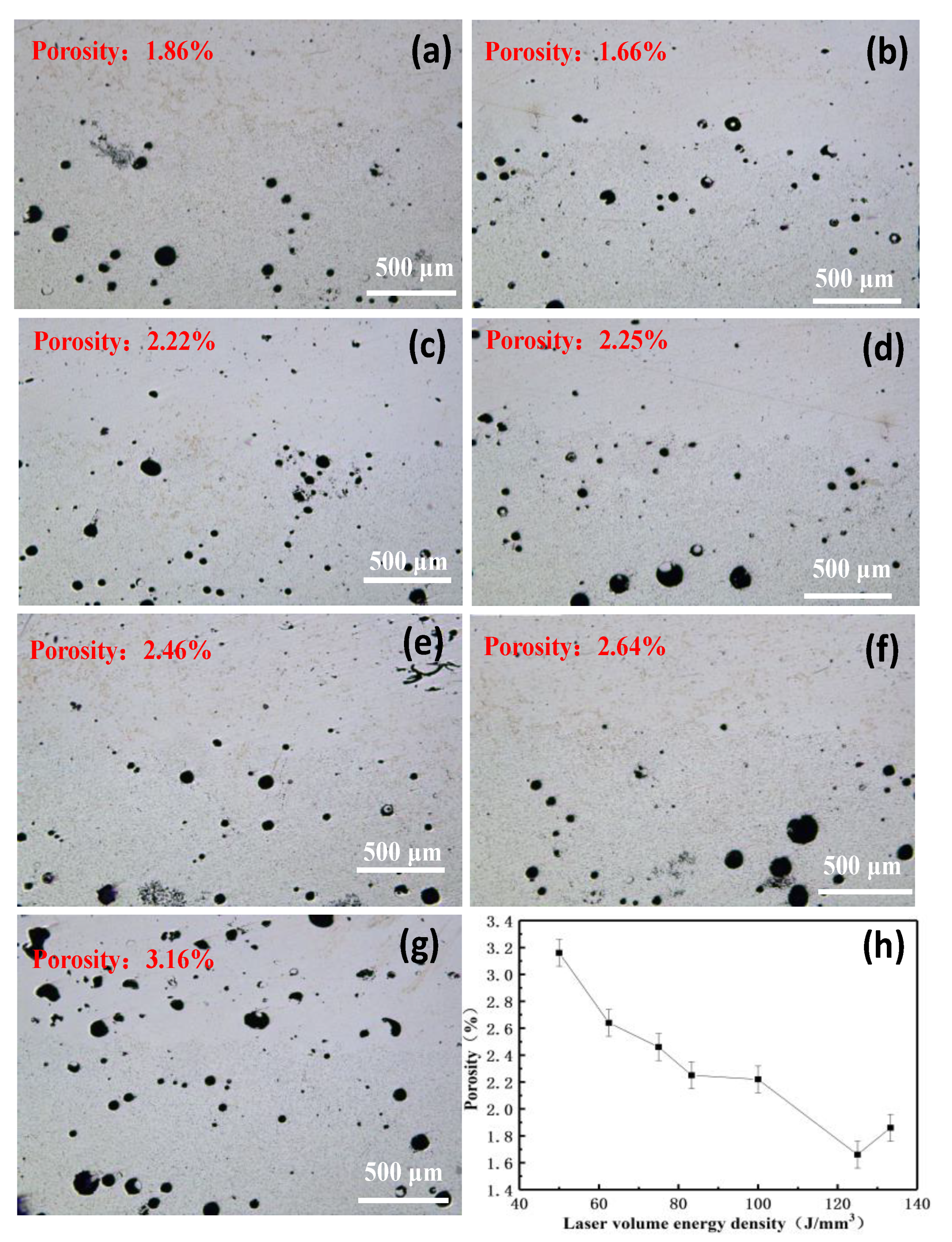
3.1. The Influence of VED on Porosity

The energy input which is known as an important factor in regulating the formation of metallurgical defects affects the degree of melting, the dynamics of the molten pool, and the solidification characteristics [27,28]. Inappropriate printing parameters during the forming process caused metallurgical defects to form, resulting in low relative density of the sample [29]. Figure 1 shows the metallographic structure of the Al-Al material interface junction under different laser VEDs and the upper part is the SLM section. It can be seen from the figure that compared with the SLM specimens, the DED aluminum alloy specimens have more pores, and the pore size is larger than that of the samples prepared by the SLM. The main reason for the above phenomenon is that the DED equipment has a larger laser power and spot diameter than the SLM equipment, which causes the DED samples to have larger molten pools. It is precisely because of the large size of the molten pool of the DED samples that the residual gas is prevented from overflowing during the printing process, which further leads to the generation of pores [30]. In addition, due to the high oxygen affinity, it is difficult to control the oxidation of the powder during the powdering and forming process, resulting in the generation of pores and even microcracks [31].
During the SLM process of the selected area, the porosity of the samples is affected by the laser energy input significantly [32]. The influence of the laser VED on the porosity of the laser melting samples in the selected area can be clearly observed in Figure 1. That is, as the VED of the laser increases, the porosity of the sample first increases to stabilize, and then finally decreases. When the laser VED is low (50 J/mm3), there are a large number of spherical pores in the selective laser melted sample. As the laser VED increases, the number of pores and the size of the pores gradually decrease. With further increase of laser VED (133.3 J/mm3), irregularly shaped keyholes appear in the samples, which increases the porosity of the sample [22].
The variation of sample porosity with different VEDs is illustrated by factors such as energy input, molten pool fluidity, quantity, as well as solidification rate [33]. In the SLM process, the high-energy laser beam sweeps across the metal powder bed, causing the powder to absorb the laser energy and melt to form molten pools. When the laser energy input is insufficient, only part of the powder in the preset area can be completely melted. On the contrast, when the laser energy input increases, the high temperature reduces the surface tension in the molten pool, improves the wettability of liquid metal, forms a large amount of low-viscosity liquid phase, promotes the diffusion of the liquid phase, and improves the metallurgical bonding between adjacent layers [32]. Therefore, a higher VED is more conducive to the wetting, spreading, and flow of the molten pool, thereby reducing porosity and increasing the relative density of the sample. However, further increasing the laser energy input will increase the solidification rate, splashing of the liquid phase, volatilization of light elements (such as Mg), and incomplete filling of the pores by the molten powder, leading to the formation of keyholes as well as increase of the porosity [34].

3.2. The Effect of VED on the Microstructure of Aluminum Alloy

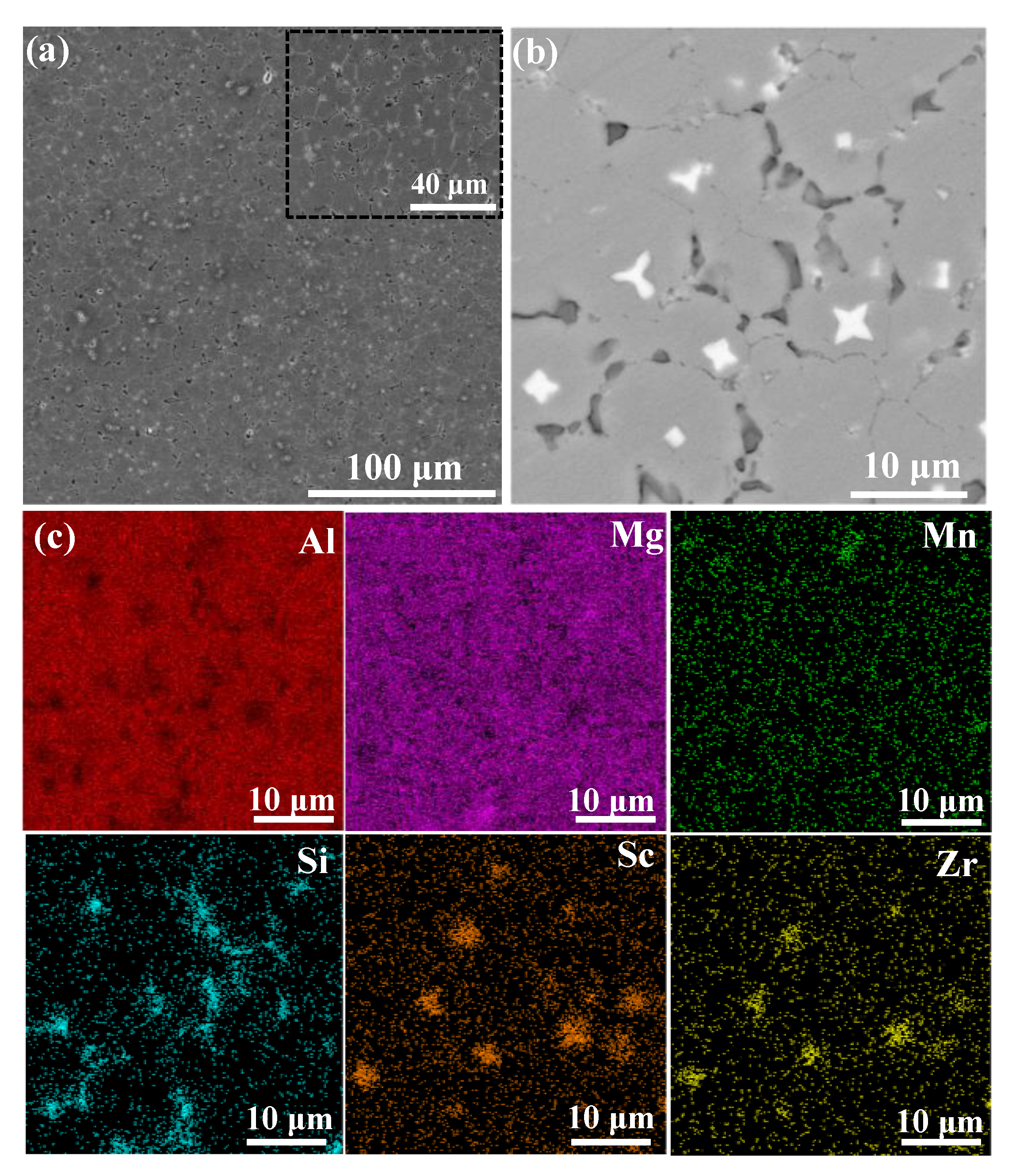
3.2.1. Microstructure of DED Aluminum Alloy

Figure 2 shows SEM images of DED aluminum alloy. It can be observed from Figure 2 that, overall, the DED aluminum alloy samples have good formability and only a small number of pores are generated. In addition, it is found that after the DED process, the microstructure of aluminum alloy is composed of equiaxed crystals. Furthermore, there are a large number of precipitated phases in the direct energy depositioned samples, and the precipitated phases are triangular due to the influence of thermodynamic factors [35]. Through further elemental analysis of the DED samples, it is found that the precipitated phase is Al3(Sc, Zr) particles rich in Sc and Zr. For aluminum alloys containing Sc/Zr elements, when the temperature in the molten pool is lower than the liquidus temperature, according to the Al-Sc binary equilibrium phase diagram, the Al-rich end shows that the primary phase precipitated after the melt is solidified as Al3(Sc, Zr) particles [24]. Generally, the size of the precipitated phase particles is nano or sub-micron [22], while the size of the precipitated phases in direct energy depositioned samples is about 3 μm. Compared with SLM, the cooling rate of the DED process is lower, which can provide enough time for the growth of precipitation phase particles, so that the growth of precipitation phase particles can be inferred. In addition, DED can easily lead to heat accumulation, which also provides conditions for the growth of precipitated particles [26]. Figure 2c shows certain discontinuous segregation and enrichment of Sc, Zr, and Si elements at the grain boundaries, which is basically consistent with the study of Wang et al. [22].

3.2.2. Microstructure of SLM Aluminum Alloy with Different VEDs

Figure 3 shows the microstructure of SLM samples under different VEDs. The morphology of the molten pool in the sample after printing can be clearly observed from the figure. It can be observed from Figure 3 that no matter at any VED, there are fine-grained regions at the boundary of the molten pool and a coarse-crystalline region (columnar region) at the center of the molten pool. During the solidification of the selective laser melted aluminum alloy, Al3(Sc, Zr) particles are precipitated from the liquid phase at the boundary of the molten pool as the primary phase, or as heterogeneous nucleation of the matrix grain [35]. The precipitated particles are pushed to the front end of solidification, which hinders the movement of grain boundary and generate a high resistance to the growth of grain, thus refining the matrix grains at the boundary of the molten pool [36]. Through the magnified observation of the boundary of the molten pool (Figure 3b), a small number of nano-precipitated particles with a radius of 80–150 nm precipitated at the boundary of the molten pool, forming a segregation zone with a width of about 6–12 μm, while only a small number of particles observed in the center of the molten pool reveals the non-uniform distribution of precipitated phases in the molten pool. Furthermore, as the VED increases, the size of the precipitated particles increases and the number decreases. In general, as the VED increases, the supercooling of the matrix is increased, and the Sc/Zr atoms are dissolved into the matrix, reducing the number of precipitated particles. With the increase of VED, multiple remelting occurs in the molten pool, resulting in a heat treatment effect [20], which increases the growth time of the precipitated phase and causes the size of the primary phase to increase.

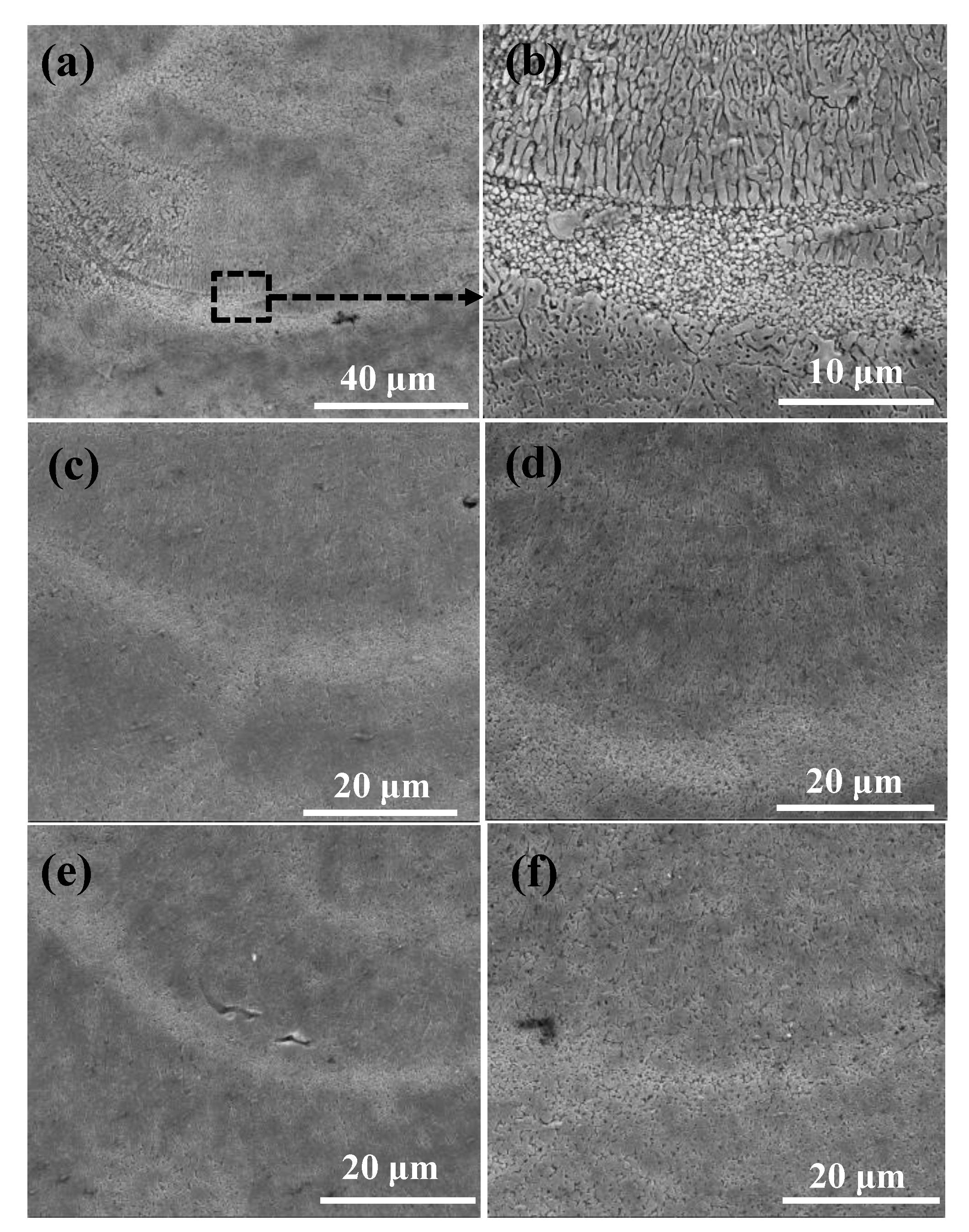
3.2.3. The Microstructure of the Interface Junction under Different VEDs
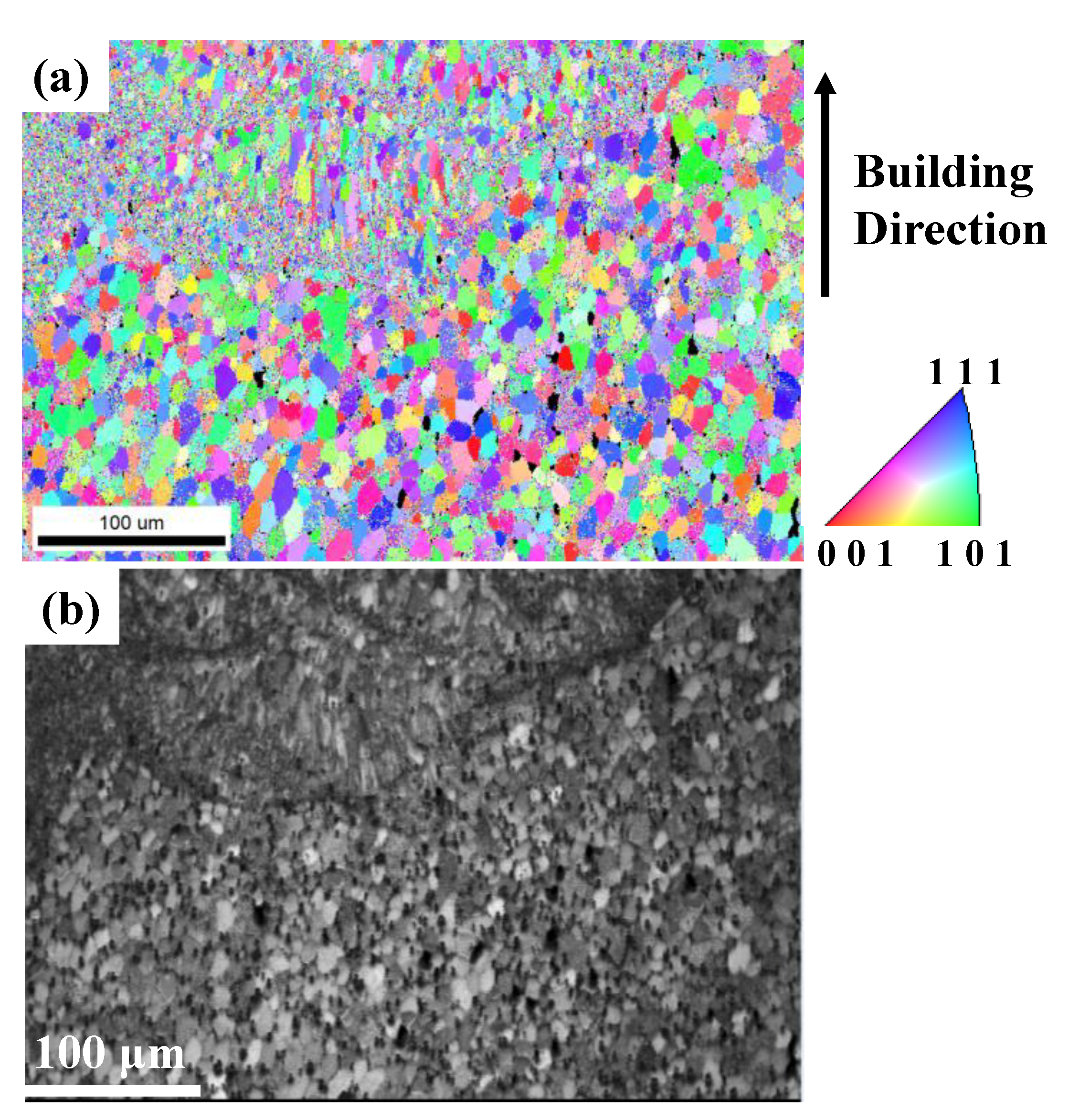
Figure 4 shows the combined morphology of SLM samples and DED samples under different laser VEDs. It can be found from the figure that under the tested laser VEDs, the selective laser melted aluminum alloy and the direct energy depositioned aluminum alloy have achieved a good metallurgical combination. In addition, the interface presents a typical wave-like morphology due to the unique properties of AM [37]. As the laser VED decreases, the width and depth of the molten pool gradually decrease. At the interface junction, the porosity gradually increases as the VED decreases. It should be noted that there are almost no defects at the interface junction because the junction is at the boundary of the molten pool, which is a fine-grained area.

3.3. EBSD Analysis

Figure 5 shows the inverse pole figure (IPF) and the image quality (IQ) map obtained by EBSD of the interface junction parallel to the building direction at 133.3 J/mm3. It can be obtained from the figure that the elongated columnar grains grow towards the center of the molten pool and fine equiaxed grains exist at the boundary of the molten pool, which agrees with the SEM results in Figure 3b. In addition, there are a number of pores shown in the DED section of the IQ map while SLM section shows no such defects. The pole figures (PFs) were obtained from the EBSD data to observe grain texture, as shown in Figure 6. Obviously, the SLM sample displays a {100} fiber texture which is the prominent observation in additively manufactured FCC alloys [38,39]. The texture is mainly caused by the retention of the intermetallic compound left by the upper layer solidification [40].
Figure 7 shows kernel average misorientation (KAM) image of the interface junction at 133.3 J/mm3, which characterizes the distribution of plastic deformation as well as residual stress. In Figure 7, the change in contrast from blue to red represents the KAM value from small to large, which means the residual stress changes from small to large [41]. As can be seen from the figure, the residual stress is mainly concentrated in the molten pools of the SLM section and the pores of the DED section. Overall, the residual stress of the aluminum alloy produced by SLM is higher than that fabricated by DED.

3.4. The Influence of VED on Interface Bonding Strength

3.4.1. The Microhardness of the Interface Junction under Different VEDs

The microhardness of the fabricated samples at the distance from the interface junction under different VEDs is shown in Figure 8a. It can be found from the figure that the microhardness of the direct energy depositioned sample is about 90 HV and the microhardness of the selective laser melted samples is as low as 110 HV. It is evident that with the increase of laser VED, the microhardness gradually increases. In addition, the maximum microhardness of the selective laser melted samples is located in the area closest to the interface junction which is the crystallite area at the boundary of the molten pool. Compared with coarse equiaxed crystals, the fine-grained region has more precipitates, thus resulting in the highest microhardness value here. In general, compared with the DED aluminum alloy samples, the SLM aluminum alloy samples have a higher microhardness value. On one hand, SLM has a higher cooling rate than DED, which leads to finer grains after solidification, on the other hand, high density of dislocations in the SLM process will hinder the slippage of grain boundaries as well as the movement of dislocations, which also contributes to the improvement of microhardness.
Figure 8b is the relationship curve between different porosities and the microhardness (HV) of the sample. It can be seen from the figure that with the increase of porosity, the bonding strength shows a downward trend, but the overall decline is not significant. The selective laser melted sample has a higher microhardness value (about 20 HV increase) than the direct energy depositioned sample. It is considered that during the SLM process, the matrix will be melted by a high-energy laser beam, and a remelting-solidification process occurs on the surface of the laser-melted aluminum alloy [42]. The microhardness is improved for the surface grains of the aluminum alloy are refined. As the VED decreases, the porosity increases and the depth of surface remelting decreases, resulting in a decrease in microhardness.
It should be noted that there is almost no difference in performance when the microhardness is applied at different positions of the interface junction [43]. The microhardness of interface is larger than that of the cladding layer and the coarse-grained region, and the molten pool bonding hardness is the measured microhardness value between the fine-crystalline region and the cladding layer.

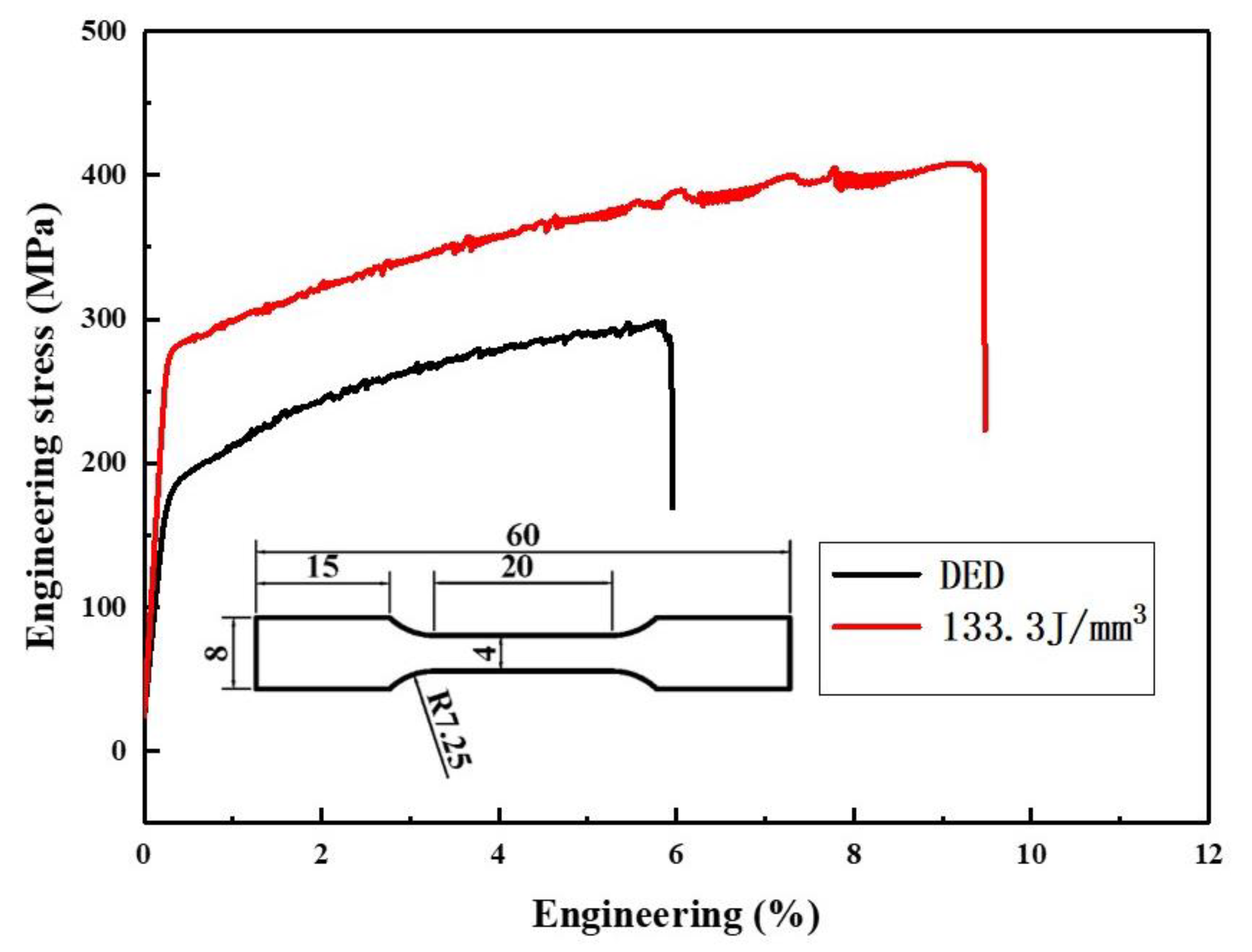
3.4.2. Tensile Property Analysis

It can be seen from the KAM image that the residual stress of the selective laser melted section is higher than that of the direct energy depositioned section, especially the residual stress near the molten pool is much higher than that of the DED. As can be seen from Figure 1, no matter at what kind of VED, the defects in the selective laser melted section are less than those in the DED. In order to research the effect of defects and residual stress on the mechanical properties of the joint, a tensile test was carried out on the dog bone specimens with VED of 133.3 J/mm3 at ambient temperature, and the results are shown in Figure 9. The yield strength (YS), tensile strength (TS), and elongation at fracture of the SLM printed sample are about 295 MPa, 400 MPa, and 9.4%, respectively, while the above indicators of the direct energy depositioned sample are about 192 MPa, 280 MPa, and 5.9%. It is clear that the tensile strength and elongation of the samples prepared by SLM are higher than those prepared by DED. On one hand, compared with the samples prepared by DED, the selective laser melted sections have a smaller grain size for its higher cooling rate; on the other hand, compared with SLM, the samples produced by DED are more likely to produce metallurgical defects in a larger molten pool, resulting in a decrease in strength and elongation. Further research found that regardless of VED, the tensile test all fractured in the DED part, which shows that compared with residual stress, defects such as pores are more likely to cause fracture.

4. Conclusions

By combining the techniques of SLM and DED, the Al-Mg-Sc-Zr alloy was additively manufactured. The microstructure, defects, and mechanical properties of the interface were mainly analyzed in this paper. The main conclusions are as follows:
  • The porosity of the samples is affected by the laser VED. With the increase of the VED, the porosity of the samples first increases to stabilize, and then finally decreases.
  • The microstructure of the aluminum alloy prepared by DED is composed of equiaxed crystals, and there are a large number of Al3(Sc, Zr) precipitated phase particles rich in Sc and Zr, while the microstructure of selective laser melted aluminum alloy is composed of equiaxed crystals and columnar crystals, and there is a fine-grained area at the boundary of the molten pool.
  • Regardless of the VED, the selective laser melted aluminum alloy and direct energy depositioned aluminum alloy have achieved good metallurgical integration. The interface presents a typical wave-like morphology. As the laser VED decreases, the width and depth of the molten pool gradually decrease. At the interface junction, the porosity gradually increases as the laser VED decreases.
  • With the porosity increases, the microhardness of selective laser melted samples shows a downward trend, but the overall decline is not significant. The selective laser melted aluminum alloy has a higher microhardness value (about 20 HV increase) compared to direct energy depositioned samples.
  • The tensile strength of the sample prepared by DED is about 280 MPa, while the tensile strength of the selective laser melted sample at 133.3 J/mm3 is as high as 400 MPa.

Author Contributions

C.D.: Writing—Original Draft Preparation, Conceptualization, Investigation; R.L.: Writing—Review and Editing, Supervision; T.Y.: Resources, Supervision; P.N.: Resources, Investigation; Y.W.: Investigation. All authors have read and agreed to the published version of the manuscript.

Funding

The authors wish to acknowledge the financial support of National Natural Science Foundation of China (51871249), Hunan Key R&D Plan (2020WK2027), Shenzhen Science and Technology Plan (JCYJ20180508151903646), Science and Technology Planning of Guangxi (AB19050002), Hunan Science Fund for Distinguished Young Scholars (2020JJ2046) and Huxiang Young talents (2018RS3007).

Institutional Review Board Statement

Not applicable.

Informed Consent Statement

Not applicable.

Data Availability Statement

Not applicable.

Conflicts of Interest

The authors declare no conflict of interest.

References

  1. Zhang, J.; Song, B.; Wei, Q.; Bourell, D.; Shi, Y. A review of selective laser melting of aluminum alloys: Processing, microstructure, property and developing trends. J. Mater. Sci. Technol. 2019, 35, 270–284. [Google Scholar] [CrossRef]
  2. Li, R.; Niu, P.; Yuan, T.; Cao, P.; Chen, C.; Zhou, K. Selective laser melting of an equiatomic CoCrFeMnNi high-entropy alloy: Processability, non-equilibrium microstructure and mechanical property. J. Alloy. Compd. 2018, 746, 125–134. [Google Scholar] [CrossRef]
  3. Yang, C.; Zhao, Y.J.; Kang, L.M.; Li, D.D.; Zhang, W.W.; Zhang, L.C. High-strength silicon brass manufactured by selective laser melting. Mater. Lett. 2018, 210, 169–172. [Google Scholar] [CrossRef]
  4. DebRoy, T.; Wei, H.L.; Zuback, J.S.; Mukherjee, T.; Elmer, J.W.; Milewski, J.O.; Beese, A.M.; Wilson-Heid, A.; De, A.; Zhang, W. Additive manufacturing of metallic components—Process, structure and properties. Prog. Mater. Sci. 2018, 92, 112–224. [Google Scholar] [CrossRef]
  5. Lu, Y.; Wu, S.; Gan, Y.; Huang, T.; Yang, C.; Junjie, L.; Lin, J. Study on the microstructure, mechanical property and residual stress of SLM Inconel-718 alloy manufactured by differing island scanning strategy. Opt. Laser Technol. 2015, 75, 197–206. [Google Scholar] [CrossRef]
  6. Zhang, H.; Zhu, H.; Qi, T.; Hu, Z.; Zeng, X. Selective laser melting of high strength Al–Cu–Mg alloys: Processing, microstructure and mechanical properties. Mater. Sci. Eng. A 2016, 656, 47–54. [Google Scholar] [CrossRef]
  7. Louvis, E.; Fox, P.; Sutcliffe, C.J. Selective laser melting of aluminium components. J. Mater. Process. Technol. 2011, 211, 275–284. [Google Scholar] [CrossRef]
  8. Prashanth, K.G.; Scudino, S.; Eckert, J. Defining the tensile properties of Al-12Si parts produced by selective laser melting. Acta Mater. 2017, 126, 25–35. [Google Scholar] [CrossRef]
  9. Zhang, H.; Zhou, C.; Wei, C. Mathematical and physical modeling of metal delivery system during top side-pouring twin-roll casting. J. Mater. Process. Technol. 2018, 254, 1–12. [Google Scholar] [CrossRef]
  10. Nie, X.; Zhang, H.; Zhu, H.; Hu, Z.; Ke, L.; Zeng, X. Analysis of processing parameters and characteristics of selective laser melted high strength Al-Cu-Mg alloys: From single tracks to cubic samples. J. Mater. Process. Technol. 2018, 256, 69–77. [Google Scholar] [CrossRef]
  11. Wang, Y.; Pan, Q.-l.; Song, Y.-f.; Li, C.; Li, Z.-f.; Chen, Q.; Yin, Z.-m. Recrystallization of Al-5.8Mg-Mn-Sc-Zr alloy. Trans. Nonferr. Met. Soc. China 2013, 23, 3235–3241. [Google Scholar] [CrossRef]
  12. Li, X.P.; Wang, X.J.; Saunders, M.; Suvorova, A.; Zhang, L.C.; Liu, Y.J.; Fang, M.H.; Huang, Z.H.; Sercombe, T.B. A selective laser melting and solution heat treatment refined Al–12Si alloy with a controllable ultrafine eutectic microstructure and 25% tensile ductility. Acta Mater. 2015, 95, 74–82. [Google Scholar] [CrossRef]
  13. Hamilton, R.F.; Bimber, B.A.; Taheri Andani, M.; Elahinia, M. Multi-scale shape memory effect recovery in NiTi alloys additive manufactured by selective laser melting and laser directed energy deposition. J. Mater. Process. Technol. 2017, 250, 55–64. [Google Scholar] [CrossRef]
  14. Li, R.; Wang, M.; Li, Z.; Cao, P.; Yuan, T.; Zhu, H. Developing a high-strength Al-Mg-Si-Sc-Zr alloy for selective laser melting: Crack-inhibiting and multiple strengthening mechanisms. Acta Mater. 2020, 193, 83–98. [Google Scholar] [CrossRef]
  15. Niu, P.; Li, R.; Fan, Z.; Yuan, T.; Zhang, Z. Additive manufacturing of TRIP-assisted dual-phases Fe50Mn30Co10Cr10 high-entropy alloy: Microstructure evolution, mechanical properties and deformation mechanisms. Mater. Sci. Eng. A 2021, 814, 141264. [Google Scholar] [CrossRef]
  16. Eisenbarth, D.; Stoll, P.; Klahn, C.; Heinis, T.B.; Meboldt, M.; Wegener, K. Unique coding for authentication and anti-counterfeiting by controlled and random process variation in L-PBF and L-DED. Addit. Manuf. 2020, 35, 101298. [Google Scholar] [CrossRef]
  17. Kruth, J.P.; Froyen, L.; Van Vaerenbergh, J.; Mercelis, P.; Rombouts, M.; Lauwers, B. Selective laser melting of iron-based powder. J. Mater. Process. Technol. 2004, 149, 616–622. [Google Scholar] [CrossRef]
  18. Guan, K.; Wang, Z.; Gao, M.; Li, X.; Zeng, X. Effects of processing parameters on tensile properties of selective laser melted 304 stainless steel. Mater. Des. 2013, 50, 581–586. [Google Scholar] [CrossRef]
  19. Thijs, L.; Verhaeghe, F.; Craeghs, T.; Humbeeck, J.V.; Kruth, J.-P. A study of the microstructural evolution during selective laser melting of Ti–6Al–4V. Acta Mater. 2010, 58, 3303–3312. [Google Scholar] [CrossRef]
  20. Peng, Y.; Li, S.; Deng, Y.; Zhou, H.; Xu, G.; Yin, Z. Synergetic effects of Sc and Zr microalloying and heat treatment on mechanical properties and exfoliation corrosion behavior of Al-Mg-Mn alloys. Mater. Sci. Eng. A 2016, 666, 61–71. [Google Scholar] [CrossRef]
  21. Shi, Y.; Rometsch, P.; Yang, K.; Palm, F.; Wu, X. Characterisation of a novel Sc and Zr modified Al–Mg alloy fabricated by selective laser melting. Mater. Lett. 2017, 196, 347–350. [Google Scholar] [CrossRef]
  22. Wang, M.; Li, R.; Yuan, T.; Chen, C.; Zhou, L.; Chen, H.; Zhang, M.; Xie, S. Microstructures and mechanical property of AlMgScZrMn—A comparison between selective laser melting, spark plasma sintering and cast. Mater. Sci. Eng. A 2019, 756, 354–364. [Google Scholar] [CrossRef]
  23. Spierings, A.B.; Dawson, K.; Heeling, T.; Uggowitzer, P.J.; Schäublin, R.; Palm, F.; Wegener, K. Microstructural features of Sc- and Zr-modified Al-Mg alloys processed by selective laser melting. Mater. Des. 2017, 115, 52–63. [Google Scholar] [CrossRef]
  24. Wang, Z.; Lin, X.; Tang, Y.; Kang, N.; Gao, X.; Shi, S.; Huang, W. Laser-based directed energy deposition of novel Sc/Zr-modified Al-Mg alloys: Columnar-to-equiaxed transition and aging hardening behavior. J. Mater. Sci. Technol. 2021, 69, 168–179. [Google Scholar] [CrossRef]
  25. Petrat, T.; Kersting, R.; Graf, B.; Rethmeier, M. Embedding electronics into additive manufactured components using laser metal deposition and selective laser melting. Procedia CIRP 2018, 74, 168–171. [Google Scholar] [CrossRef]
  26. Simchi, A. Direct laser sintering of metal powders: Mechanism, kinetics and microstructural features. Mater. Sci. Eng. A 2006, 428, 148–158. [Google Scholar] [CrossRef]
  27. Yan, Q.; Song, B.; Shi, Y. Comparative study of performance comparison of AlSi10Mg alloy prepared by selective laser melting and casting. J. Mater. Sci. Technol. 2020, 41, 199–208. [Google Scholar] [CrossRef]
  28. Wang, M.; Song, B.; Wei, Q.; Shi, Y. Improved mechanical properties of AlSi7Mg/nano-SiCp composites fabricated by selective laser melting. J. Alloy. Compd. 2019, 810, 151926. [Google Scholar] [CrossRef]
  29. Bai, Y.; Yang, Y.; Xiao, Z.; Zhang, M.; Wang, D. Process optimization and mechanical property evolution of AlSiMg0.75 by selective laser melting. Mater. Des. 2018, 140, 257–266. [Google Scholar] [CrossRef]
  30. Wan, L.; Shi, S.; Xia, Z.; Shi, T.; Zou, Y.; Li, K.; Chen, X. Directed energy deposition of CNTs/AlSi10Mg nanocomposites: Powder preparation, temperature field, forming, and properties. Opt. Laser Technol. 2021, 139, 106984. [Google Scholar] [CrossRef]
  31. Kimura, T.; Nakamoto, T. Microstructures and mechanical properties of A356 (AlSi7Mg0.3) aluminum alloy fabricated by selective laser melting. Mater. Des. 2016, 89, 1294–1301. [Google Scholar] [CrossRef]
  32. Qiu, C.; Panwisawas, C.; Ward, M.; Basoalto, H.C.; Brooks, J.W.; Attallah, M.M. On the role of melt flow into the surface structure and porosity development during selective laser melting. Acta Mater. 2015, 96, 72–79. [Google Scholar] [CrossRef] [Green Version]
  33. Shi, Y.; Yang, K.; Kairy, S.K.; Palm, F.; Wu, X.; Rometsch, P.A. Effect of platform temperature on the porosity, microstructure and mechanical properties of an Al–Mg–Sc–Zr alloy fabricated by selective laser melting. Mater. Sci. Eng. A 2018, 732, 41–52. [Google Scholar] [CrossRef]
  34. Gu, J.; Gao, M.; Yang, S.; Bai, J.; Ding, J.; Fang, X. Pore formation and evolution in wire + arc additively manufactured 2319 Al alloy. Addit. Manuf. 2019, 30, 100900. [Google Scholar] [CrossRef]
  35. Spierings, A.B.; Dawson, K.; Uggowitzer, P.J.; Wegener, K. Influence of SLM scan-speed on microstructure, precipitation of Al3Sc particles and mechanical properties in Sc- and Zr-modified Al-Mg alloys. Mater. Des. 2018, 140, 134–143. [Google Scholar] [CrossRef]
  36. Aversa, A.; Lorusso, M.; Cattano, G.; Manfredi, D.; Calignano, F.; Ambrosio, E.P.; Biamino, S.; Fino, P.; Lombardi, M.; Pavese, M. A study of the microstructure and the mechanical properties of an AlSiNi alloy produced via selective laser melting. J. Alloy. Compd. 2017, 695, 1470–1478. [Google Scholar] [CrossRef]
  37. Mishra, A.K.; Kumar, A. Numerical and experimental analysis of the effect of volumetric energy absorption in powder layer on thermal-fluidic transport in selective laser melting of Ti6Al4V. Opt. Laser Technol. 2019, 111, 227–239. [Google Scholar] [CrossRef]
  38. Peng, H.; Xie, S.; Niu, P.; Zhang, Z.; Yuan, T.; Ren, Z.; Wang, X.; Zhao, Y.; Li, R. Additive manufacturing of Al0.3CoCrFeNi high-entropy alloy by powder feeding laser melting deposition. J. Alloy. Compd. 2021, 862, 158286. [Google Scholar] [CrossRef]
  39. Wei, H.L.; Elmer, J.W.; DebRoy, T. Origin of grain orientation during solidification of an aluminum alloy. Acta Mater. 2016, 115, 123–131. [Google Scholar] [CrossRef] [Green Version]
  40. Liu, J.; To, A.C. Quantitative texture prediction of epitaxial columnar grains in additive manufacturing using selective laser melting. Addit. Manuf. 2017, 16, 58–64. [Google Scholar] [CrossRef]
  41. Li, Y.; Zhou, K.; Tan, P.; Tor, S.B.; Chua, C.K.; Leong, K.F. Modeling temperature and residual stress fields in selective laser melting. Int. J. Mech. Sci. 2018, 136, 24–35. [Google Scholar] [CrossRef]
  42. Huang, K.; Zhang, K.; Marthinsen, K.; Logé, R.E. Controlling grain structure and texture in Al-Mn from the competition between precipitation and recrystallization. Acta Mater. 2017, 141, 360–373. [Google Scholar] [CrossRef]
  43. Croteau, J.R.; Griffiths, S.; Rossell, M.D.; Leinenbach, C.; Kenel, C.; Jansen, V.; Seidman, D.N.; Dunand, D.C.; Vo, N.Q. Microstructure and mechanical properties of Al-Mg-Zr alloys processed by selective laser melting. Acta Mater. 2018, 153, 35–44. [Google Scholar] [CrossRef]
Figure 1. Optical microscope pictures under different laser VEDs: (a) 133.3 J/mm3; (b) 125 J/mm3; (c) 100 J/mm3; (d) 83.3 J/mm3; (e) 75 J/mm3; (f) 62.5 J/mm3; (g) 50 J/mm3; and (h) the relationship between laser VED and porosity.
Metals 11 00801 g001
Figure 2. Microstructure and element distribution of DED aluminum alloy. (a) SEM picture of DED aluminum alloy at low magnification; (b) SEM picture at high magnification; (c) EDS map of the corresponding element distribution in the selected area.
Metals 11 00801 g002
Figure 3. The microstructure of the SLM aluminum alloy samples under different VEDs: (a,b) 133.3 J/mm3; (c) 100 J/mm3; (d) 75 J/mm3; (e) 62.5 J/mm3; (f) 50 J/mm3.
Metals 11 00801 g003
Figure 4. The combined morphology of SLM samples and DED samples under different VEDs: (a,d) 133.3 J/mm3; (b) 100 J/mm3; (c) 75 J/mm3; (e) 62.5 J/mm3; (f) 50 J/mm3.
Metals 11 00801 g004
Figure 5. (a) IPF orientation map of interface junction parallel to the building direction with VED of 133.3 J/mm3 and (b) IQ map of interface junction.
Metals 11 00801 g005
Figure 6. PFs showing the (a) {100}, (b) {110}, and (c) {111} crystallographic directions of interface junction parallel to the building direction with VED of 133.3 J/mm3.
Metals 11 00801 g006
Figure 7. KAM image obtained from EBSD data of the interface junction at 133.3 J/mm3.
Metals 11 00801 g007
Figure 8. (a) The microhardness of the interface junction under different VEDs and (b) The microhardness of the interface junction under different porosities.
Metals 11 00801 g008
Figure 9. Tensile strength of DED sample and SLM sample with VED of 133.3 J/mm3 and accurate geometry of the tensile specimens.
Metals 11 00801 g009
Table 1. Chemical composition (wt.%) of the alloy powder.
MgScZrMnSiAl
6.520.480.270.400.56Bal.
Publisher’s Note: MDPI stays neutral with regard to jurisdictional claims in published maps and institutional affiliations.

