Article

Optimizing the Integrity of Linear Friction Welded Ti2AlNb Alloys

1
Xi’an Rare Metal Materials Institute Co., Ltd., Xi’an 710072, China
2
State Key Laboratory of Solidification Processing, Northwestern Polytechnical University, Xi’an 710072, China
*
Authors to whom correspondence should be addressed.
Metals 2021, 11(5), 802; https://doi.org/10.3390/met11050802
Submission received: 13 April 2021 / Revised: 8 May 2021 / Accepted: 11 May 2021 / Published: 14 May 2021

Abstract

:
The knowledge of process parameters–weld integrity-aging treatments–tensile property relationship is of great concern for linear friction welded (LFWed) Ti2AlNb-based alloy and requires a systematic characterization. Thus, the Ti2AlNb-based alloy was LFWed under various process parameters and then subjected to different aging treatments. Twelve welding conditions were used to evaluate the weld integrity, showing that impurities and cracks at weld interface can be eliminated under strong welding parameters and the feed rate has the greatest influence on the weld integrity among all process parameters. Relationships among aging temperatures, microstructure evolution, and mechanical properties were investigated. After aging treatment, acicular O phase has precipitated in B2 grains both in the weld zone and thermo-mechanical affected zone (TMAZ). The size of precipitated O phase increases along with the increase of temperature, and the α2 + O mixtures have finally decomposed into the aggregated acicular O phase. The microhardness and tensile strength of the joints have been enhanced due to the precipitation hardening of O phase and refined grain strengthening after aging treatments.

1. Introduction

The Ti2AlNb-based alloys have been developed by the addition of niobium to Ti3Al-based intermetallic alloys [1,2,3,4]. As the ordered orthorhombic Ti2AlNb phase (O phase) can inhibit dislocation motion and crack propagation [5,6], Ti2AlNb-based alloys possess higher specific strength, fracture toughness, creep resistance at 650~750 °C [7,8], and especially better processability than Ti3Al-based alloys [9]. These advantages have made Ti2AlNb-based alloys become one of the most potential lightweight high-temperature structural materials for aero-engines [10,11].
To date, research focused on the fusion welding techniques for Ti2AlNb-based alloys has been reported, including on laser welding [12,13] and electron beam welding [14,15]. However, typical solidification structures such as coarse columnar grain and segregation generated beyond melting point of materials during fusion welding process are hard to be eliminated, which inevitably impair the strength of joint [16,17,18,19]. Linear friction welding (LFW), as a solid-state welding process, may be an excellent solution to avoid this problem [20,21,22]. In the LFW process, friction heat is created by the relative reciprocating motion of two components under compressive force [23,24,25]. The thermomechanical coupling process could refine grains effectively and consequently achieve sound joints with excellent properties. Therefore, it is especially suitable for the connection of Ti2AlNb-based alloy [26].
It has been reported that strengthening effect of O phase is absent due to the transformation from O to B2 phase during the welding process, and the grain size distribution in the weld zone is not uniform, which both deteriorate the mechanical properties of the joint [27,28,29]. Heat treatment is proven to be effective to optimize the microstructure and properties of Ti2AlNb-based alloys [30,31]. Post-welding heat treatment (PWHT) could improve the homogeneity in microstructure of the joint, restore the deformation caused by welding, and strengthen the joint performance via precipitation hardening [32,33]. Several works had been done about PHWT for LFWed Ti2AlNb-based alloys, but the influence of different aging temperatures on the microstructure and mechanical properties of joints are still not clear at present [28,34,35]. In addition, little work has been published on the integrity of LFWed alloys, although detailed microstructure evolution across the weld have been reported [36,37,38,39,40]. Process parameters such as amplitude, frequency, feed rate, and pressures applied during welding and upsetting phases are the basic LFW parameters that determine the amount of axial shortening and the flash formation, which are crucial for extrusion of impurities presenting at the interface during LFW [41].
Therefore, the microstructure of linear friction welding Ti2AlNb-based alloys under different LFW parameters (friction pressure, amplitude, frequency, upsetting force, and feed rate) have been characterized to investigate the quality and the formation mechanism of the joint. In addition, the effect of aging treatments on microstructure evolution and mechanical properties of LFWed Ti2AlNb-based alloys were investigated as well as the relevant strengthening mechanism of O phase.

2. Materials and Methods

The as received Ti2AlNb-based alloys were forged and then solution treated at 980 °C followed by air cooling, and their corresponding chemical composition is shown in Table 1.
Figure 1 shows a typical B2 + α2 + O tri-phase microstructure of Ti2AlNb-based alloys, in which the black granular phase is α2 phase, the light gray needle phase is O phase, and the substrate is B2 phase.
The welding test was carried out on the XMH-250 welding machine developed at Shaanxi Provincial Key Laboratory of Friction Welding (China). The selection of welding parameters shown in Table 2 was based on the previous experiments conducted by the authors. Linear friction welding is a process where one component (oscillation side) is moved in a direct reciprocating mode relative to another part (applied force side) under normal pressure [36]. The feed rate is defined as the speed of the applied force side moving towards the oscillation side during the welding process, which can be set in XMH-250 welding machine. To avoid the excessive flash extrusion, the welding process is controlled by preset axial shrinkage instead of welding time in 10# to 12# conditions.
The heat treatment was carried out in a muffle furnace, and the furnace temperature was calibrated with a platinum-rhodium-platinum thermocouple meter to ensure the accuracy of temperature. Considering the strengthening effect of O phase to the alloy, aging treatments were carried out at 760, 800, and 840 °C in the O + B2 two-phase zone followed by air cooling to study the effect of aging temperature on the microstructure evolution and mechanical properties of the joints.
The metallographic sample is first polished from 70# to 2000# with water abrasive sandpaper. The polishing fluid alumina was used for rough polishing, and then chromium trioxide was used for fine polishing. The sample was etched with a solution of 3ml HF, 30 mL HNO3 and 67 mL H2O. The optical microscope (OM) (Olympus, Tokyo, Japan) and scanning electron microscope (SEM) were observed on LCS300 optical microscope (Cewei, Xi’an, China) and Vega II XMU scanning electron microscope (Tescan, Brno, Czech Republic), respectively. The phase compositions were identified using an X-ray diffractometer (XRD) (Philips, Amsterdam, Netherlands) with Cu Kα radiation and the operating parameters were 40 kV and 30 mA, and the 2θ range spanned from 30 to 80° with a step size of 0.02° and a scan step time of 1s. Volume fraction was estimated by using a software Image Pro Plus (Media Cybernetics, Rockville, MD, USA).
The microhardness was measured at intervals of 200 μm from the weld zone to base metal with a microhardness tester (Duramin-A300, load 200 g, dwell time 10 s) for welded joints and heat-treated joints. Tensile samples are processed according to GB/6397-86 (China). The tensile sample was mechanically polished from 70# to 800# with abrasive paper. Tensile test was performed on Shimadzu Ag-X test machine (Shimadzu, Kyoto, Japan), and the strain rate of the test was 10−2 s−1.

3. Results and Discussion

3.1. Bonding Rate

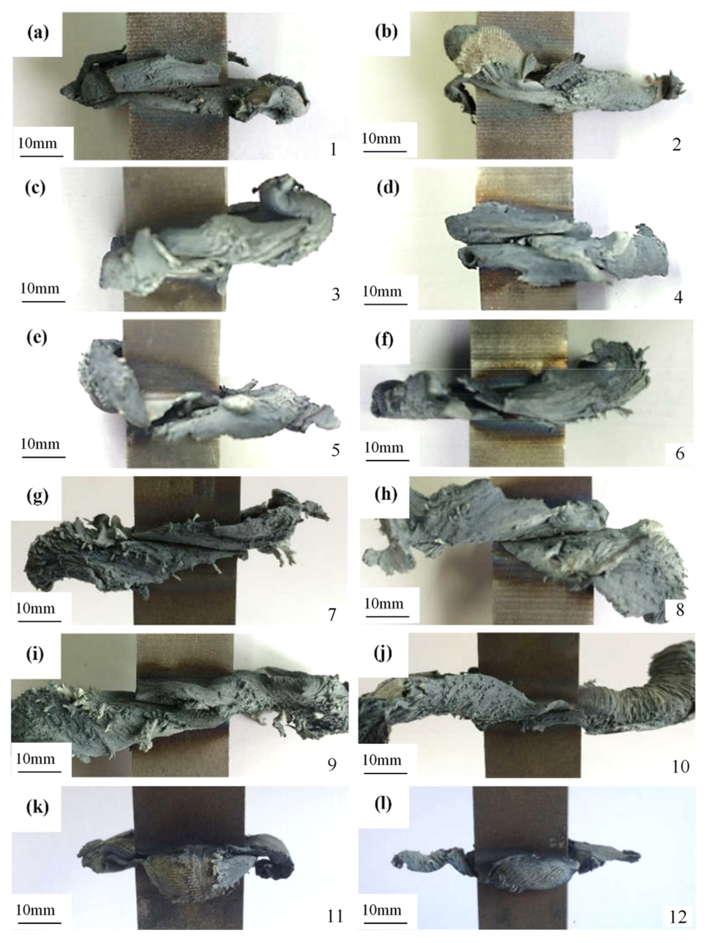
3.1.1. Joint Appearance

The appearance joints obtained under 1#–12# conditions in Table 2 are shown in Figure 2. In the following, Joints No. 1 to No. 12 represent the welded joints obtained under the1# to 12# conditions, respectively.
According to the appearance of the joints No. 1 to No. 3 (shown in Figure 2a–c), it can be found that under the weak welding condition parameters (i.e., small friction pressure, upsetting pressure, and amplitude with long friction time), although the amount of flash extrusion increases with the increase of the welding time, the flash of all three joints fails to completely seal the weld, indicating weld failure. The appearance of the joints No. 4 to No. 6 is shown in Figure 2d–f. With the increase of amplitude, the amount of flash extrusion increases compared with that of joints No. 1 to No. 3, but the flash morphology changes little. As a result, increasing the amplitude alone has no significant effect on the improvement of the joint quality.
As shown in Figure 2g–i, as the friction pressure and upsetting pressure increased, the amount of flash extrusion from Joints No. 7 to No. 9 increases significantly. However, the flash morphology of the three joints is irregular, asymmetrical, and discontinuous, and flash from both sides is still not adhesive. Therefore, it can be concluded that the amount of flash extrusion is positively correlated with the friction pressure, upsetting pressure and amplitude, that is, the greater the friction pressure, the upsetting pressure or the amplitude, the more amount of extruded flash.
Compared with the No. 9 joint, the No. 10 joint welded at higher feed rate but lower welding time while fixing the friction pressure and upsetting pressure. As shown in Figure 2j, No. 10 joint has no obvious change in the amount of flash extrusion compared with No. 9 joint, but the distribution of flash is more uniform and continuous and bilaterally symmetrical, indicating a higher bonding rate of No. 10 joint t than that of previous joints. It is assumed that the welding quality can be effectively improved by increasing the feed rate. 11# condition furtherly increase the feed rate from 3 to 5mm/s. As shown in Figure 2k, the amount of flash extrusion of No. 11 joint is moderate, and the flash at both sides is continuous and completely adhesive. Compared with the 11# condition, the 12# condition only increases the upsetting pressure. The flash of No. 12 joint exhibits similar distribution to that of No. 11 joint, indicating the achievement of a sound joint.

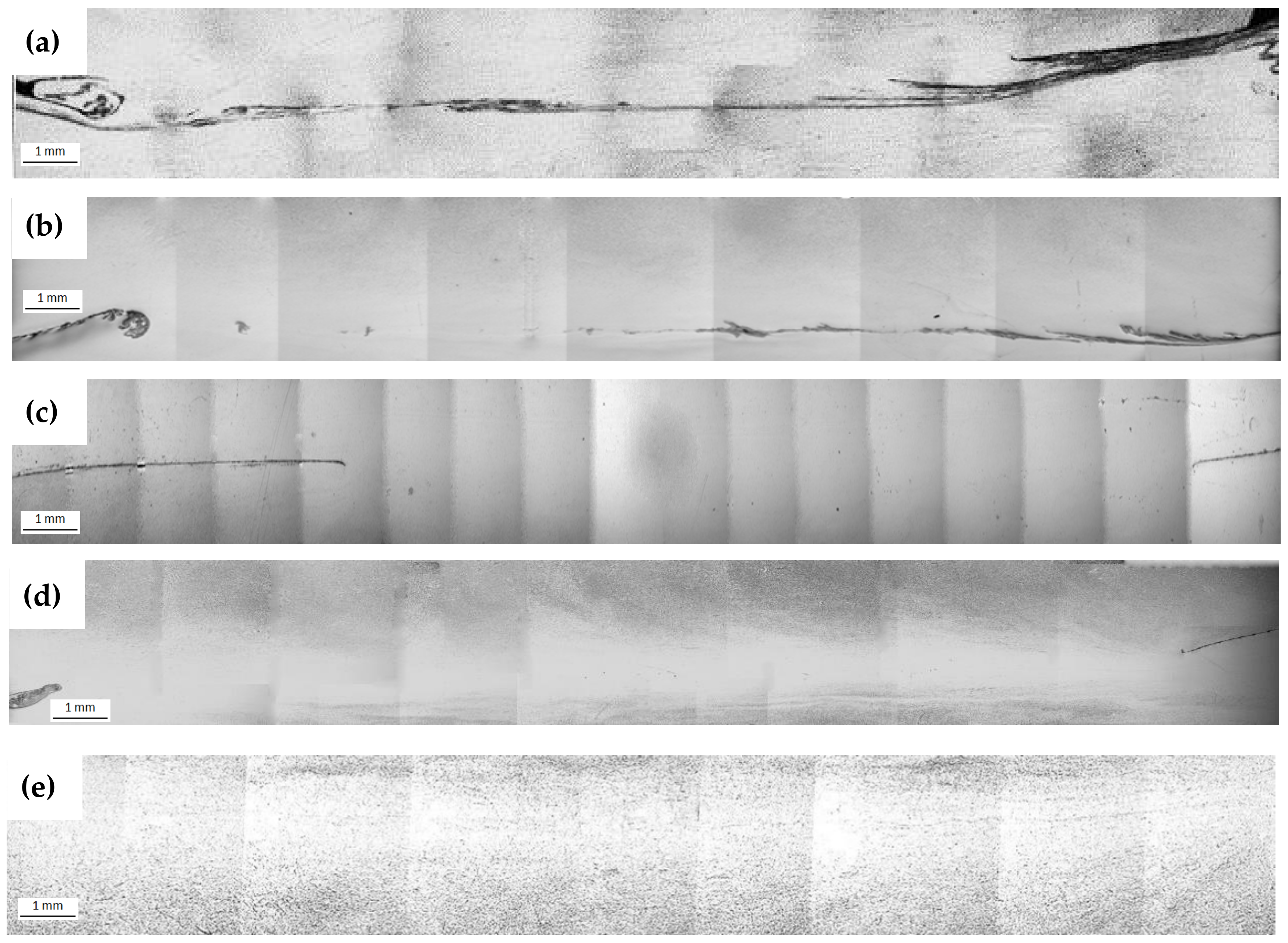
3.1.2. Overall View of Joints

In order to further verify the welding quality of joints, the representative No. 6, No. 9, No. 10, No. 11, and No. 12 joints were selected for metallographic analysis and the corresponding microstructure is shown in Figure 3.
The overall view of the cross-sectional microstructure of No. 6, No. 9, No. 10, No. 11, and No. 12 joint are shown in Figure 3a–e, respectively. It can be seen from No. 6 joint that cracks and impurities have distributed all over the weld line. Cracks and impurities of No. 9 joint are significantly reduced compared to No. 6 joint while increasing the friction and upsetting pressure. In comparison to No. 9 joint, the bonding rate of No. 10 joint is significantly improved as the feed rate was increased from 1.5 to 3 mm/s. With furtherly increase the feed rate to 5 mm/s, the unwelded area in joint No. 11 has almost disappeared, with only a little cracks and impurities distributing at the edge of the weld line. Due to the self-cleaning behavior of LFW process, the impurities are apt to be extruded from weld center under friction and upsetting pressure. In general, the friction and upsetting pressure is highest in weld center [42], as a result, with increasing the friction and upsetting pressure, higher bonding rate can be achieved for No. 9 joint compared to No. 6 joint. In addition, the self-cleaning behavior can be enhanced with increasing the feed rate. Thus, No. 12 joint is free of impurities by utilizing highest feed rate and upsetting pressure among all joints.

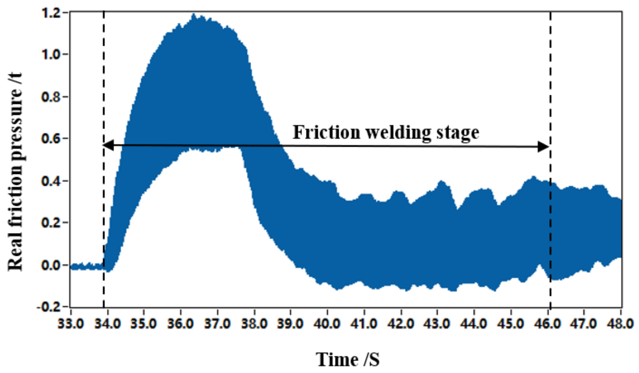
3.1.3. Process Variables

The linear friction welding control process can be divided into the six stages: the clamping stage, the automatic adjustment of the pre-weld interval stage, the start-up of the frequency converter until the stationary stage, the friction welding stage, the returning stage, and the upsetting stage. According to previous study of the authors, the curve of friction pressure during friction welding stage can reflect the influence of the feed rate on the joint quality [43]. Therefore, the No. 9 joint (70 MPa, 1.5 mm/s) and No. 12 joint (70 MPa, 5 mm/s) were selected for further specific analysis of friction pressure curves.
The friction pressure curves of No. 9 and No. 12 joints obtained during welding process are shown in Figure 4 and Figure 5, respectively. Although the friction pressure used for No. 9 and No. 12 joints are fixed at 70 MPa, the real friction pressure during welding process of No. 9 joint is lower than that of No. 12 joint. Moreover, it should be noted that the real friction pressure of No. 9 joint has exhibited negative values during the late friction welding stage. For LFW process, most thermoplastic materials are generated and then extruded from weld interface during friction welding stage. In other words, the thermoplastic materials formed in weld interface are “dynamically regenerated”. If the amount of regenerated thermoplastic materials failed to supply the amount of extruded thermoplastic materials at low feed rate, the non-contacted area at weld interface will be formed and lead to the decline of real friction pressure. As a result, the impurities are failed to be self-cleaned along with the extrusion of thermoplastic materials.
To sum up, the weak welding parameters, i.e., the low friction pressure, upsetting pressure, amplitude, and feed rate, will lead to low bonding rate of joints, while the joint with 100% bonding rate can be obtained under strong welding parameters, i.e., the large friction pressure, upsetting pressure, amplitude, and feed rate. The feed rate has the greatest influence on the bonding rate of the joint.

3.2. Microstructures Evolution

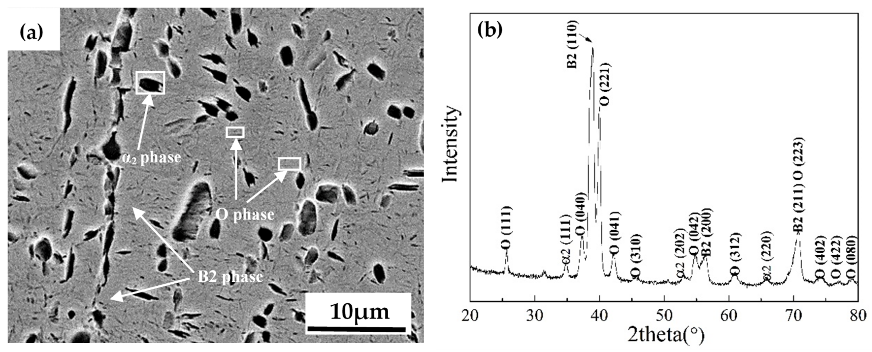
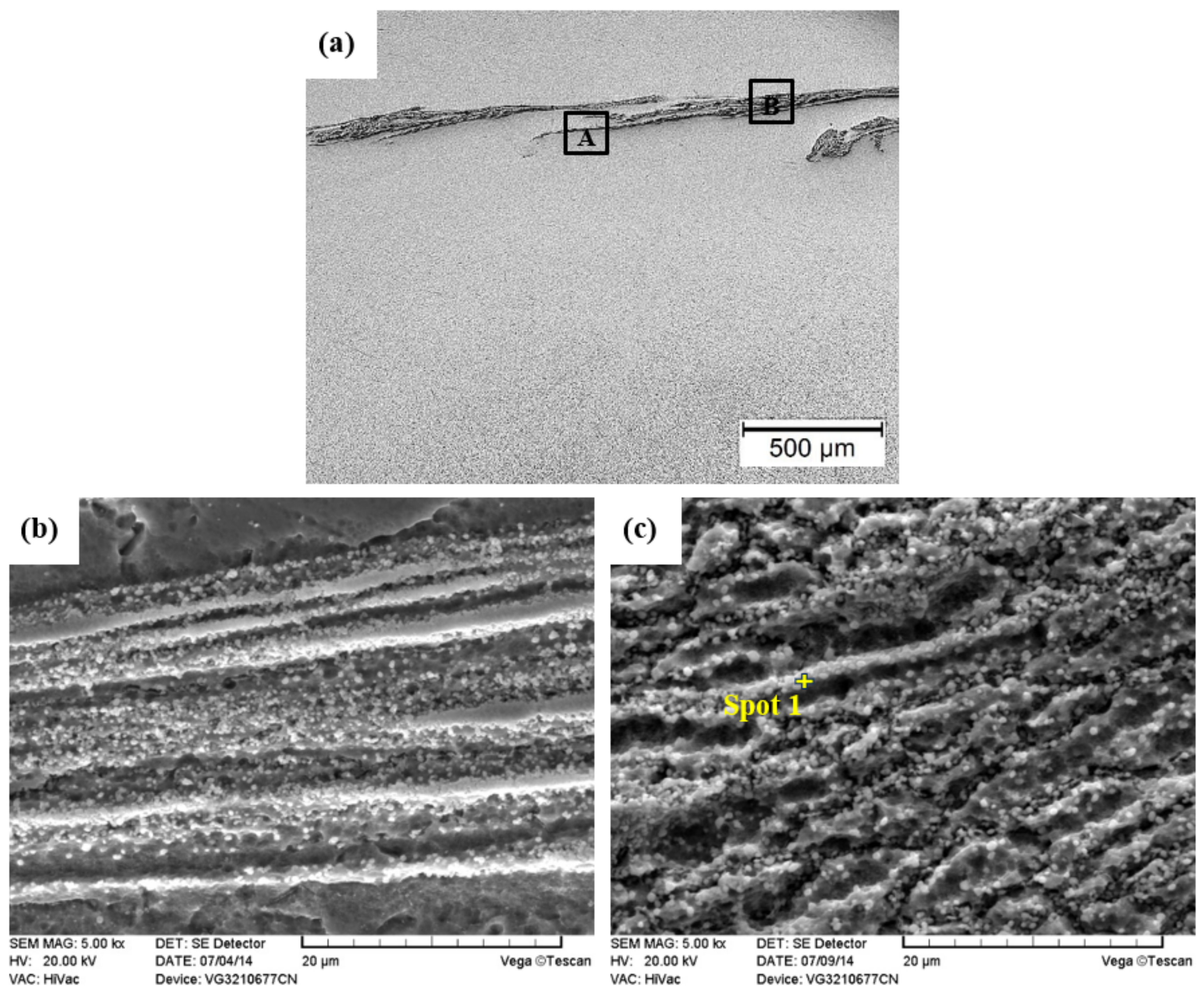
3.2.1. Unwelded Area

The typical unwelded areas of No. 9 joint were selected for microstructure characterization. Figure 6a shows the microstructure at the edge of weld line by OM, and corresponding microstructures at high magnification of Zone A and B by SEM are shown in Figure 6b,c, respectively. Instead of typical α2, O and B2 phase, crushed material particles have distributed along the weld line in this area.
Figure 7 shows the microstructure of the unwelded area at weld center. As compared to that at the edge of the weld line, the width of this area is significantly reduced due to the highest friction and upsetting pressure in the weld center. Its microstructures have gradually exhibited a little common characteristics of weld zone, such as grain boundaries. However, it is also observed in this area that a large number of white particles have dispersed on the substrate (Figure 7b). Higher magnification of the B zone reveals cracks and voids along the grain boundary (Figure 7c), which undoubtedly have adverse effect on joint quality. For No. 9 joint, the negative real friction pressure during friction stage will lead to insufficient heat input and weaken the fluidity of thermoplastic materials. Consequently, the crushed particles generated in initial process failed to be extruded from the weld interface along with the extrusion of thermoplastic materials and formed the unwelded area.
The EDS results of spot 1 and 2 in Figure 6c and Figure 7c are shown in Table 3. No oxygen element exists in these two regions, illustrating that in spite of the existence of negative real friction pressure in the late friction welding stage, the oxides generated in the initial stage still can be extruded out of the welding interface.

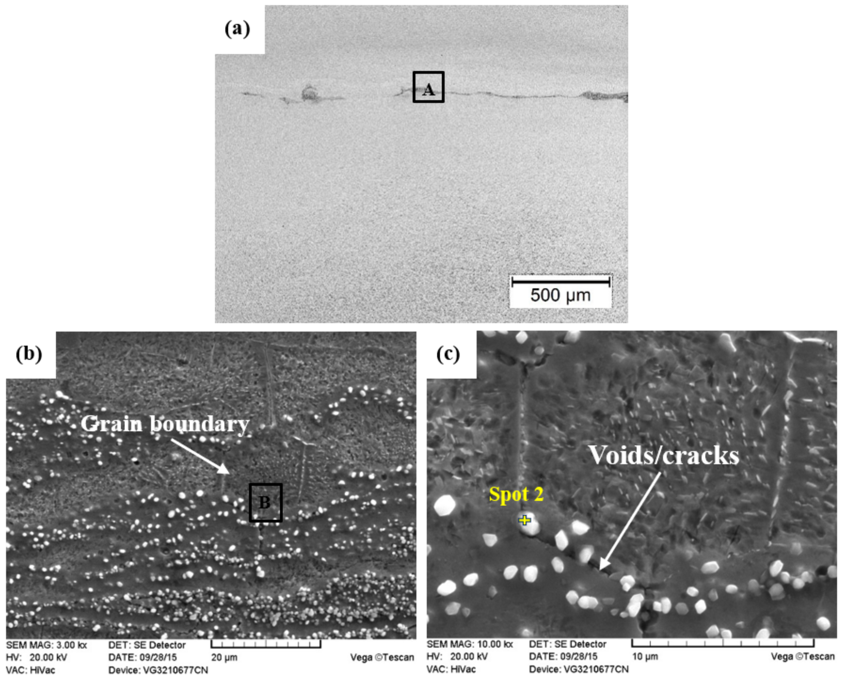
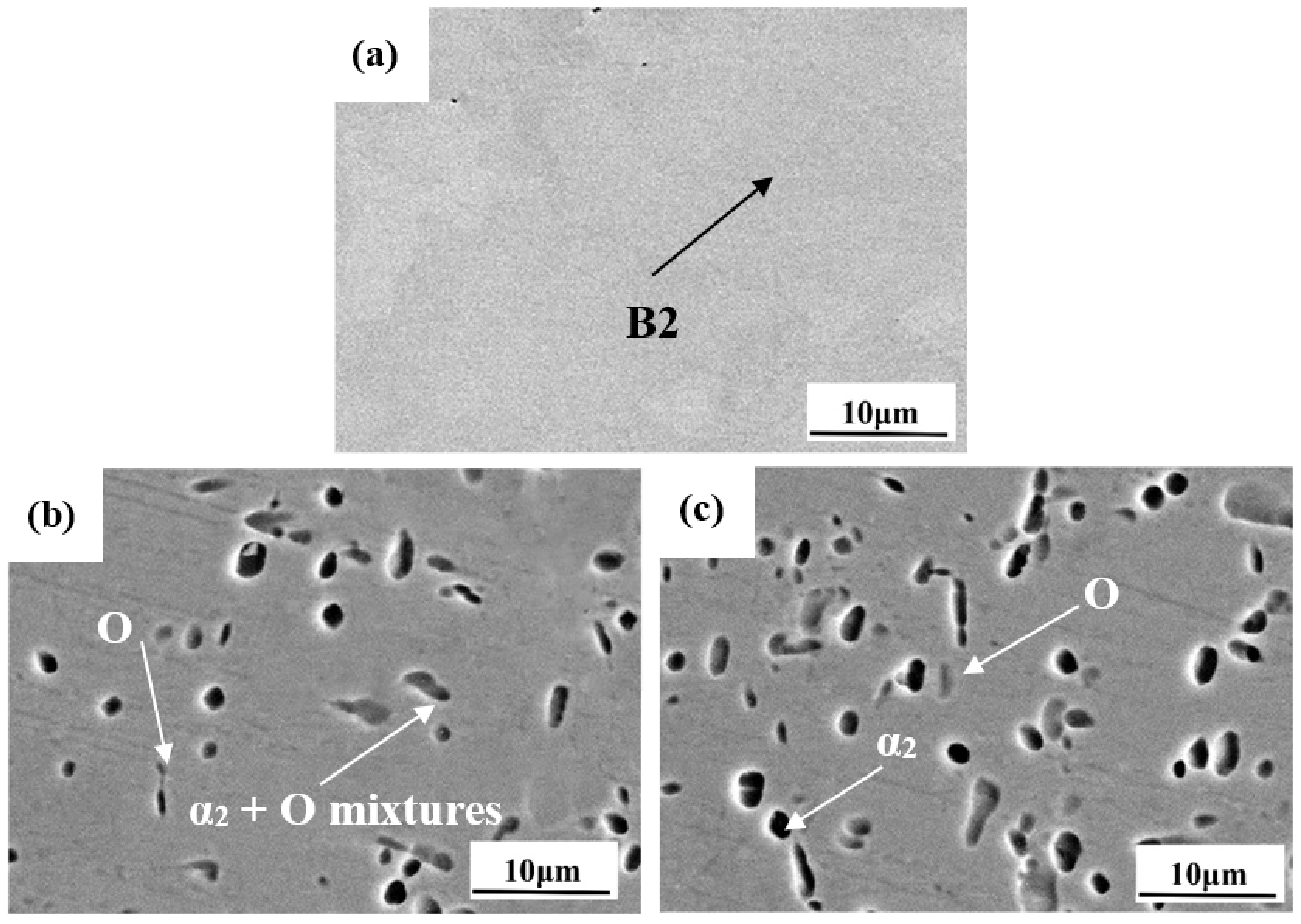
3.2.2. As Welded Joint

Figure 8 shows the SEM images of the typical weld zone, near weld zone and far weld zone in thermo-mechanical affected zone (TMAZ) of No. 12 joint. As shown in Figure 8a, the weld area is mainly composed of B2 phase, and the primary α2 and O phases have almost disappeared. The XRD result of the weld zone shown in Figure 9 is related to the morphology, and it shows that the main phase composition in the weld zone is B2 phase which is body-centered cubic. It can be seen from Figure 8b that in the area near the weld, the residual O phase is coarsened, and the α2 phase transforms to the α2 + O mixture. There are more O phases in the far weld zone (Figure 8c), but the morphology of α2 phase changes little [44].

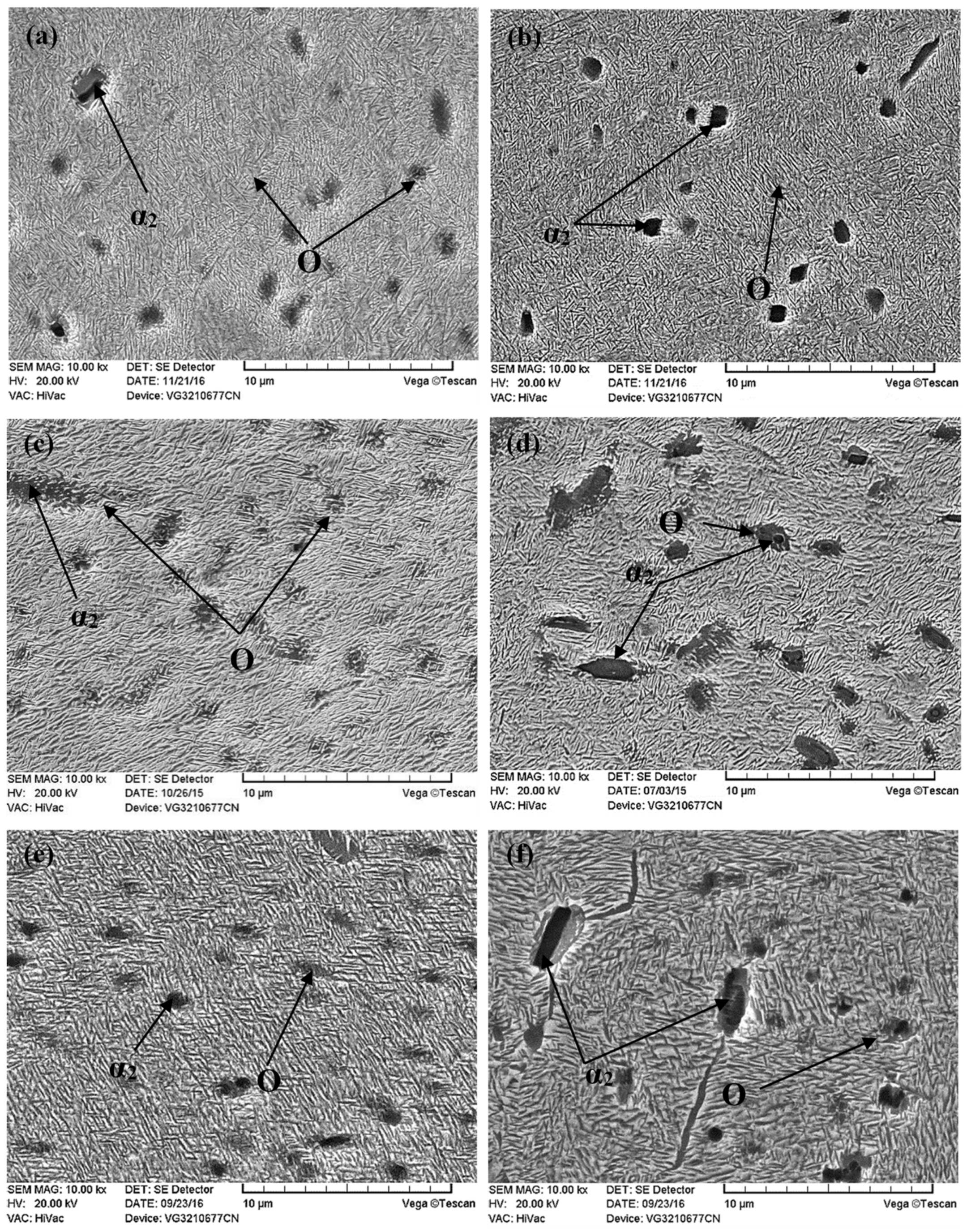
3.3. Aging Treatment

3.3.1. Weld Zone

The microstructures of the weld zone after aging at different temperatures are shown in Figure 10. Driven by heat treatment, static recovery and recrystallization can promote the development of low-angle grain boundaries into large-angle grain boundaries, which gradually transform sub-grains into new recrystallized grains. As shown in Figure 10a,c,e, equiaxed recrystallized grains are observed in the weld zone. Generally, when the heat treatment temperature is 10% of the melting point of the alloy, static recovery occurs, and when the temperature is 40% or more, the deformed alloy can be recrystallized. The melting point of the Ti2AlNb-based alloys is generally around 1600 °C, which means the recrystallization can be satisfied beyond 640 °C. The aging temperature applied in this paper is beyond 760 °C, indicating that the temperature is high enough to provide sufficient driving force for the recovery and recrystallization in weld zone. The black dot shown in Figure 10d is α2 phase, indicating that the aging treatment cannot eliminate the remaining α2 phase during the welding process.
High-magnification microstructures of the weld zone after aging at 760, 800, and 840 °C are given in Figure 10b,d,f, respectively. It is found that as the aging temperature increases, the O precipitated in the weld zone grows significantly. The O phase obtained by the aging treatment is the same as the precipitation mechanism of the O phase in the weld zone during the solution treatment in the O + B2 phase region: the B2 phase is transformed into orthogonal O phase with ordered structure through the ordering arrangement of intermediate transition phase O’ phase (with B19 structure). However, due to the high temperature of solid solution treatment, the acicular O-phase and the lamellar O-phase in the weld zone are larger, while the O-phase precipitated in the weld zone after the aging treatment exhibits a fine acicular morphology.
The XRD results of the weld zone after aging at different temperatures are shown in Figure 11. It can be seen that, with the increase of aging temperature, the relative peak intensity of the O phase increases at first and then decreases, indicating that the amount of precipitation of the O phase increases at first and then decreases. In addition, the variation of the volume fraction of O phase at different aging temperatures given in Table 4 also confirms this assumption. In general, the volume fraction of the O phase decreases as the heating temperature increases. However, due to the relatively low temperature of 760 °C, the driving force provided for the phase transition from B2 → B2 + O is not sufficient, resulting in the lowest volume fraction of O precipitates. Both the acicular O phase in B2 grain and the O phase distributed on the grain boundary are smaller than those aged at 800 and 840 °C.

3.3.2. TMAZ

The microstructures of the near-weld zone after aging treatment at 760, 800, and 840 °C are shown in Figure 12a,c,e, respectively. It can be found that the growth of the fine acicular O phase and the decomposition of α2 + O mixtures during the aging treatment increases with the increase of temperature.
Most α2 + O mixtures still retain the equiaxed form indicating the insufficient decomposition of α2 phase at 760 °C. With the aging temperature rising to 800 and 840 °C, the α2 + O mixtures in the near-weld zone has almost been transformed into the acicular O phase. The microstructure characteristics of the far-weld zone after aging treatment at different temperatures are given in Figure 12b,d,f. It can be seen that the transformation of the acicular O phase in far-weld zone has a similar variation trend compared to that in the near-weld zone. After aging at 760 °C, the α2 phase in the far-weld zone hardly changed compared with the as-welded condition, while the rim-O phase began to precipitate around the α2 phase until the temperature was raised above 800 °C. This phenomenon indicates that the decomposition of the α2 phase is mainly affected by temperature. Xue et al. [45] found that the degree of precipitation of O phase in α2 particles is mainly related to the heating temperature and holding time, while the nucleation mode of O phase at the edge of α2 phase is similar to layer-by-layer nucleation. Since the high concentration gradient between the interface of α2 and B2 phase could facilitate the element diffusion, the O phase is apt to nucleate and grow from the edge of the α2 phase.

3.4. Mechanical Properties

The microhardness distribution of the joint after aging is shown in Figure 13. After aging treatment at 760, 800, and 840 °C, the microhardness values of the weld zone were increased by approximately 95, 11 101 HV, respectively. It is worth noting that the highest hardness value occurs at 800 °C, which shows the microhardness values of the joint are not proportional to the aging temperatures. The microhardness of the Ti2AlNb-based alloys is mainly defined by the type and volume fraction of the precipitated phase, while the thickness of the lamellar O phase has little effect on the microhardness [46]. Therefore, at the aging temperature of 800 °C, the joint has the highest microhardness because of the highest volume fraction of O phase. Although the finest acicular O phase can be obtained at 760 °C, the microhardness value is the lowest due to the lowest volume fraction of the O phase.
The tensile properties of the joints after aging at different temperatures are given in Table 5. The elongation of the joint increases with the increase of the aging temperature, while the tensile strength of the joint increases first but then decreases. For Ti2AlNb-based alloys, the finer the O phase, the better tensile strength of the alloy, while the thicker O phase improves the plasticity and toughness but impairs the strength of the alloy [47,48]. According to the previous analysis, the size of acicular O phase precipitated during the aging treatment increases with increasing temperature; therefore, the 840 °C aging joint has the best tensile ductility and relatively lower strength. After aging treatment at 760 °C, although fine acicular O phase can be obtained, its low volume fraction limits the strengthening effect on the tensile properties of the joint. The fracture structure of tensile specimens aged at different temperatures is shown in Figure 14. After aging treatment at 760 °C, the fracture surface consists of tearing ridges and a few small dimples, indicating a quasi-cleavage fracture mode. With increasing the aging temperature (Figure 14c,d), the amount and the depth of dimples increase, showing the enhancement of joint ductility.

4. Conclusions

  • The welding parameters for linear friction welding of Ti2AlNb-based alloys have a significant effect on the joint quality. The joint with 100% bonding rate can be obtained under strong welding parameters, i.e., the large friction pressure, upsetting pressure, amplitude, and feed rate.
  • The weld zone of linear friction welding joint of Ti2AlNb-based alloys consists of B2 matrix and residual O and α2 phase. Most of the O phases in TMAZ have gradually transformed into B2 phase, while the α2 phase has transformed into α2 + O mixtures. After aging treatment, acicular O phase has precipitated in both the weld zone and TMAZ. The size of the acicular O phase precipitated during aging treatment increases with the increase of temperature. The decomposition of α2 + O mixtures has finally resulted in the formation of aggregated acicular O phase.
  • Due to the lack of precipitation strengthening effect of O phase, the microhardness of linear friction welded Ti2AlNb joint is obviously lower than that of base metal. After aging treatment, O phase precipitation hardening and fine grain strengthening significantly increase the microhardness and tensile strength of the joint.

Author Contributions

Conceptualization, X.C.; methodology, X.C.; software, W.L. and T.M.; investigation, X.C.; resources, Z.Z., W.L., and D.S.; data curation, X.C.; writing—original draft preparation, X.C. and Z.Z.; writing—review and editing, Z.Z.; visualization, X.W.; supervision, F.X. All authors have read and agreed to the published version of the manuscript.

Funding

This research received no external funding.

Data Availability Statement

Not applicable.

Conflicts of Interest

The authors declare no conflict of interest.

References

  1. Wang, G.; Sui, X.; Liu, Q.; Liu, Y. Fabricating Ti2AlNb sheet with high tensile strength and good ductility by hot packed rolling the spark plasma sintered pre-alloyed powder. Mater. Sci. Eng. A 2021, 801, 140392. [Google Scholar] [CrossRef]
  2. Shao, B.; Shan, D.; Guo, B.; Zong, Y. Plastic deformation mechanism and interaction of B2, α2, and O phases in Ti-22Al-25Nb alloy at room temperature. Int. J. Plast. 2019, 113, 18–34. [Google Scholar] [CrossRef]
  3. Liang, X.; Liu, Z.; Li, H.; Chen, F.; Yang, W.; Ouyang, S.; Liu, Y.; Wang, L. Microstructure and elevated-temperature mechanical properties of in situ Ti2AlNb-reinforced TiAl-matrix composite prepared by powder metallurgy. Mater. Today Commun. 2020, 24, 101179. [Google Scholar] [CrossRef]
  4. Zhang, Y.; Liu, Y.; Yu, L.; Liang, H.; Huang, Y.; Ma, Z. Microstructures and tensile properties of Ti2AlNb and Mo-modified Ti2AlNb alloys fabricated by hot isostatic pressing. Mater. Sci. Eng. A 2020, 776, 139043. [Google Scholar] [CrossRef]
  5. Zhu, L.; Tang, B.; Ding, M.-X.; Liu, Y.; Chen, X.-F.; Yan, S.-P.; Li, J.-S. Interface characteristic and mechanical performance of TiAl/Ti2AlNb diffusion bonding joint with pure Ti interlayer. Rare Met. 2020, 39, 1402–1412. [Google Scholar] [CrossRef]
  6. Esin, V.; Mallick, R.; Dadé, M.; Denand, B.; Delfosse, J.; Sallot, P. Combined synchrotron X-ray diffraction, dilatometry and electrical resistivity in situ study of phase transformations in a Ti2AlNb alloy. Mater. Charact. 2020, 169, 110654. [Google Scholar] [CrossRef]
  7. Singh, A.K.; Sarma, B.N.; Lele, S. Order–disorder transformation of the O phase in Ti2AlNb alloys. Philos. Mag. 2004, 84, 2865–2876. [Google Scholar] [CrossRef]
  8. Huang, Y.; Liu, Y.; Li, C.; Ma, Z.; Yu, L.; Li, H. Microstructure evolution and phase transformations in Ti-22Al-25Nb alloys tailored by super-transus solution treatment. Vacuum 2019, 161, 209–219. [Google Scholar] [CrossRef]
  9. Qu, S.J.; Feng, A.H.; Shagiev, M.R.; Xie, H.; Li, B.B.; Shen, J. Superplastic behavior of the fine-grained Ti-21Al-18Nb-1Mo-2V-0.3Si intermetallic alloy. Lett. Mater. 2018, 8, 567–571. [Google Scholar] [CrossRef] [Green Version]
  10. Zhang, Y.; Feng, A.; Qu, S.; Shen, J.; Chen, D. Microstructure and low cycle fatigue of a Ti2AlNb-based lightweight alloy. J. Mater. Sci. Technol. 2020, 44, 140–147. [Google Scholar] [CrossRef]
  11. Goyal, K.; Sardana, N. Phase stability and microstructural evolution of Ti2AlNb alloys-a review. Mater. Today Proc. 2020, 41, 951–968. [Google Scholar] [CrossRef]
  12. Lei, Z.; Zhang, K.; Zhou, H.; Ni, L.; Chen, Y. A comparative study of microstructure and tensile properties of Ti2AlNb joints prepared by laser welding and laser-additive welding with the addition of filler powder. J. Mater. Process. Technol. 2018, 255, 477–487. [Google Scholar] [CrossRef]
  13. Zhang, K.; Lei, Z.; Chen, Y.; Yan, C.; Fu, Q.; Bao, Y. High-temperature Tensile Behavior of Laser Welded Ti-22Al-25Nb Joints at Different Temperatures. J. Wuhan Univ. Technol. Sci. Ed. 2020, 35, 1116–1121. [Google Scholar] [CrossRef]
  14. Li, Y.-J.; Wu, A.-P.; Li, Q.; Zhao, Y.; Zhu, R.-C.; Wang, G.-Q. Mechanism of reheat cracking in electron beam welded Ti2AlNb alloys. Trans. Nonferr. Met. Soc. China 2019, 29, 1873–1881. [Google Scholar] [CrossRef]
  15. Wang, S.; Chen, Y.; Li, L. Effect of beam deviation on electron beam welded Ti-22Al-25Nb/TC4 dissimilar alloys. Weld. World 2020, 64, 661–670. [Google Scholar] [CrossRef]
  16. Xu, M.; Liu, B.; Zhao, Y.; Wang, Z.; Dong, Z. Direct joining of thermoplastic ABS to aluminium alloy 6061-T6 using friction lap welding. Sci. Technol. Weld. Join. 2020, 25, 391–397. [Google Scholar] [CrossRef]
  17. Zhenmin, W.; Donghang, J.; Jianwen, W.; Mengjia, X. A review on high-frequency pulsed arc welding. J. Manuf. Process. 2020, 60, 503–519. [Google Scholar] [CrossRef]
  18. Oliveira, J.P.; Schell, N.; Zhou, N.; Wood, L.; Benafan, O. Laser welding of precipitation strengthened Ni-rich NiTiHf high temperature shape memory alloys: Microstructure and mechanical properties. Mater. Des. 2019, 162, 229–234. [Google Scholar] [CrossRef]
  19. Zhang, K.; Lei, Z.; Ni, L.; Zhou, H.; Chen, Y. Improvement in microstructure and high-temperature brittleness of laser-welded Ti-22Al-25Nb joints with the addition of TiB2 powder. J. Mater. Process. Technol. 2021, 288, 116848. [Google Scholar] [CrossRef]
  20. Ballat-Durand, D.; Bouvier, S.; Risbet, M.; Pantleon, W. Through analysis of the microstructure changes during linear friction welding of the near-α titanium alloy Ti-6Al-2Sn-4Zr-2Mo (Ti6242) towards microstructure optimization. Mater. Charact. 2019, 151, 38–52. [Google Scholar] [CrossRef]
  21. Masoumi, F.; Shahriari, D.; Monajati, H.; Cormier, J.; Flipo, B.; Devaux, A.; Jahazi, M. Linear friction welding of AD730™ Ni-base superalloy: Process-microstructure-property interactions. Mater. Des. 2019, 183, 108117. [Google Scholar] [CrossRef]
  22. Matsuda, T.; Adachi, H.; Sano, T.; Yoshida, R.; Hori, H.; Ono, S.; Hirose, A. High-frequency linear friction welding of aluminum alloys to stainless steel. J. Mater. Process. Technol. 2019, 269, 45–51. [Google Scholar] [CrossRef]
  23. Turner, R.; Howe, D.; Thota, B.; Ward, R.; Basoalto, H.; Brooks, J. Calculating the energy required to undergo the conditioning phase of a titanium alloy inertia friction weld. J. Manuf. Process. 2016, 24, 186–194. [Google Scholar] [CrossRef]
  24. McAndrew, A.R.; Colegrove, P.A.; Bühr, C.; Flipo, B.C.; Vairis, A. A literature review of Ti-6Al-4V linear friction welding. Prog. Mater. Sci. 2018, 92, 225–257. [Google Scholar] [CrossRef]
  25. Fratini, L.; Buffa, G.; Cammalleri, M.; Campanella, D. On the linear friction welding process of aluminum alloys: Experimental insights through process monitoring. CIRP Ann. 2013, 62, 295–298. [Google Scholar] [CrossRef]
  26. Tan, L.J.; Yao, Z.K.; Wang, T.; Guo, H.Z.; Yang, X.; Tan, A.C. Microstructure evolution of friction welded dissimilar joint during subsequent hot work. Mater. Sci. Technol. 2011, 27, 1701–1706. [Google Scholar] [CrossRef]
  27. Li, X.; He, J.; Zhang, T.; Tao, J.; Li, J.; Zhang, Y. Effect of Heat Treatment on the Microstructure and Properties of a Ti3Al Linear Friction Welding Joint. Materials 2019, 12, 1159. [Google Scholar] [CrossRef] [Green Version]
  28. Chen, X.; Xie, F.; Ma, T.; Li, W.; Wu, X. Effects of post-weld heat treatment on microstructure and mechanical properties of linear friction welded Ti2AlNb alloy. Mater. Des. 2016, 94, 45–53. [Google Scholar] [CrossRef]
  29. Li, Y.M.; Liu, C.X.; Yu, L.M.; Li, H.J.; Wang, Z.M.; Liu, Y.C.; Li, W.Y. Effect of High-Temperature Ageing on Microstructure and Mechanical Properties of Linear Friction Welded S31042 Steel Joint. Acta Metall. Sin. 2018, 54, 981–990. [Google Scholar] [CrossRef]
  30. Song, L.; Wang, L.; Zhang, T.; Lin, J.; Pyczak, F. Microstructure and phase transformations of ωo-Ti4Al3Nb based alloys after quenching and subsequent aging at intermediate temperatures. J. Alloys Compd. 2020, 821, 153387. [Google Scholar] [CrossRef]
  31. Shao, B.; Zong, Y.; Wen, D.; Tian, Y.; Shan, D. Investigation of the phase transformations in Ti 22Al 25Nb alloy. Mater. Charact. 2016, 114, 75–78. [Google Scholar] [CrossRef]
  32. Zhang, H.; Li, C.; Ma, Z.; Huang, Y.; Yu, L.; Liu, Y. Static coarsening behavior of a pre-deformed Ti2AlNb-based alloy during heat treatment. Vacuum 2019, 169, 108934. [Google Scholar] [CrossRef]
  33. Zhao, M.; Chiew, S.; Lee, C. Post weld heat treatment for high strength steel welded connections. J. Constr. Steel Res. 2016, 122, 167–177. [Google Scholar] [CrossRef] [Green Version]
  34. Rajan, S.; Wanjara, P.; Gholipour, J.; Kabir, A.S. Microstructure, Tensile Properties, and Fatigue Behavior of Linear Friction-Welded Ti-6Al-2Sn-4Zr-2Mo-0.1Si. Materials 2020, 14, 30. [Google Scholar] [CrossRef]
  35. Rajan, S.; Wanjara, P.; Gholipour, J.; Kabir, A.S. Joining of Dissimilar Alloys Ti-6Al-4V and Ti-6Al-2Sn-4Zr-2Mo-0.1Si Using Linear Friction Welding. Materials 2020, 13, 3664. [Google Scholar] [CrossRef]
  36. Li, W.; Vairis, A.; Preuss, M.; Ma, T. Linear and rotary friction welding review. Int. Mater. Rev. 2016, 61, 71–100. [Google Scholar] [CrossRef]
  37. Geng, P.; Qin, G.; Zhou, J.; Zou, Z. Hot deformation behavior and constitutive model of GH4169 superalloy for linear friction welding process. J. Manuf. Process. 2018, 32, 469–481. [Google Scholar] [CrossRef]
  38. Li, Y.; Liu, Y.; Liu, C.; Li, C.; Ma, Z.; Huang, Y.; Wang, Z.; Li, W. Microstructure evolution and mechanical properties of linear friction welded S31042 heat-resistant steel. J. Mater. Sci. Technol. 2018, 34, 653–659. [Google Scholar] [CrossRef]
  39. Guo, Z.; Ma, T.; Li, W.; Zhang, Y.; Zhao, Z.; Tao, J.; Kang, W. Intergrowth Bonding Mechanism and Mechanical Property of Linear Friction Welded Dissimilar Near-Alpha to Near-Beta Titanium Alloy Joint. Adv. Eng. Mater. 2021, 2001479. [Google Scholar] [CrossRef]
  40. Li, Y.; Guo, X.; Chen, B.; Li, P.; Guo, Q.; Ding, R.; Yu, L.; Su, Y.; Li, W. Microstructure and Mechanical Properties of Linear Friction Welding Joint of GH4169 Alloy/S31042 Steel. Acta Metall. Sin. 2021, 57, 363–374. [Google Scholar] [CrossRef]
  41. Chamanfar, A.; Jahazi, M.; Gholipour, J.; Wanjara, P.; Yue, S. Maximizing the integrity of linear friction welded Waspaloy. Mater. Sci. Eng. A 2012, 555, 117–130. [Google Scholar] [CrossRef]
  42. Yang, X.; Li, W.; Fu, Y.; Ye, Q.; Xu, Y.; Dong, X.; Hu, K.; Zou, Y. Finite element modelling for temperature, stresses and strains calculation in linear friction welding of TB9 titanium alloy. J. Mater. Res. Technol. 2019, 8, 4797–4818. [Google Scholar] [CrossRef]
  43. Yang, X.; Li, W.; Feng, Y.; Yu, S.; Xiao, B. Physical simulation of interfacial microstructure evolution for hot compression bonding behavior in linear friction welded joints of GH4169 superalloy. Mater. Des. 2016, 104, 436–452. [Google Scholar] [CrossRef]
  44. Chen, X.; Xie, F.; Ma, T.; Li, W.; Wu, X. Microstructure evolution and mechanical properties of linear friction welded Ti2AlNb alloy. J. Alloys Compd. 2015, 646, 490–496. [Google Scholar] [CrossRef]
  45. Xue, C.; Zeng, W.; Wang, W.; Liang, X.; Zhang, J. Quantitative analysis on microstructure evolution and tensile property for the isothermally forged Ti2AlNb based alloy during heat treatment. Mater. Sci. Eng. A 2013, 573, 183–189. [Google Scholar] [CrossRef]
  46. Wei, W.; Weidong, Z.; Chen, X.; Xiaobo, L.; Jianwei, Z. Designed bimodal size lamellar O microstructures in Ti 2 AlNb based alloy: Microstructural evolution, tensile and creep properties. Mater. Sci. Eng. A 2014, 618, 288–294. [Google Scholar] [CrossRef]
  47. Fu, Y.; Lv, M.; Zhao, Q.; Zhang, H.; Cui, Z. Investigation on the size and distribution effects of O phase on fracture properties of Ti2AlNb superalloy by using image-based crystal plasticity modeling. Mater. Sci. Eng. A 2021, 805, 140787. [Google Scholar] [CrossRef]
  48. Huang, Z.-S.; Lin, P.; Shen, J. Origin of the O phase and its effect on the mechanical properties of rolled Ti-22Al-25Nb alloy sheets. Mater. High Temp. 2021, 38, 103–113. [Google Scholar] [CrossRef]
Figure 1. (a) Microstructure and (b) XRD patterns of Ti-22Al-25Nb alloy.
Metals 11 00802 g001
Figure 2. Typical appearance of as-LFWed joints under welding conditions: (al) correspond to the joint obtained under 1#–12# condition.
Metals 11 00802 g002
Figure 3. Overall view of as-LFWed joints by OM: (a) No. 6, (b) No. 9, (c) No. 10, (d) No. 11, and (e) No. 12.
Metals 11 00802 g003
Figure 4. Friction pressure curve of LFWed No. 9 joint.
Metals 11 00802 g004
Figure 5. Friction pressure curve of LFWed No. 12 joint.
Metals 11 00802 g005
Figure 6. Microstructure of defect zone at the edge by: (a) OM at low magnification, (b) high magnification of zone A in (a) by SEM, and (c) high magnification of zone B in (a) by SEM.
Metals 11 00802 g006
Figure 7. Microstructure of defect zone in the center by: (a) OM image at low magnification, (b) high magnification of zone A in (a) by SEM, and (c) high magnification of zone B in (b) by SEM.
Metals 11 00802 g007
Figure 8. Microstructure of (a) weld zone, (b) near-weld zone in TMAZ, and (c) far-weld zone in TMAZ by SEM, respectively.
Metals 11 00802 g008
Figure 9. XRD patterns of weld zone.
Metals 11 00802 g009
Figure 10. Micrographs of weld zone after aging treatment: (a) 760 °C and (b) high magnification of the (a); (c) 800 °C and (d) high magnification of the (c); (e) 840 °C n and (f) high magnification of the (e).
Metals 11 00802 g010
Figure 11. X-ray diffraction peaks of weld zone under different aging treatment conditions.
Metals 11 00802 g011
Figure 12. Micrographs of TMAZ by SEM: (a) near-weld zone and (b) far-weld zone after 760 °C aging, (c) near-weld zone and (d) far-weld zone after 800 °C aging, (e) near-weld zone and (f) far-weld zone after 840 °C aging.
Metals 11 00802 g012
Figure 13. Microhardness profiles of the joint from weld zone to base metal under different aging conditions.
Metals 11 00802 g013
Figure 14. SEM fractography of the aging treated joint after tensile test: (a) 760 °C, macro; (b) 760 °C, micro; (c) 800 °C, macro; (d) 800 °C, micro; (e) 840 °C, macro; (f) 840 °C, micro.
Metals 11 00802 g014
Table 1. Chemical compositions of Ti2AlNb-based alloys (wt.%).
ElementTiAlNbONH
ContentBalance10.6542.680.0560.00550.0015
Table 2. Welding parameters for Ti2AlNb-based alloys.
Parameters1#2#3#4#5#6#7#8#9#10#11#12#
Friction pressure/MPa505050505050606070707070
Forging pressure/MPa100100100100100100110120120120120130
Amplitude/mm222333333333
Frequency/Hz242424242424262626262626
Time/s68106810666///
Feed rate/mm/s1.51.51.51.51.51.51.51.51.53.05.05.0
Table 3. EDS spectra of spots 1 and 2.
No.Elementwt.%at.%
Spot 1Al8.4818.05
Ti43.7352.42
Nb47.7929.53
Spot 2Al6.7513.51
Ti59.2466.74
Nb34.0119.76
Table 4. Volume fraction of α2, O, and B2 phase for weld zone under different aging conditions.
Temperatureα2 (%)O (%)B2 (%)
760 °C/40.9359.07
800 °C/45.2154.79
840 °C/42.3757.63
Table 5. Profiles of tensile tests under different aging treatment conditions.
SampleHeat Treatment TemperatureUTS (MPa)YS (MPa)Elongation (%)Fraction Location
Base metal/1203 ± 101117 ± 205.8 ± 0.3/
As welded [44]/1036 ± 7976 ± 264.4 ± 0.3Weld zone
AT1760 °C/2 h/AC1118 ± 111108 ± 183.6 ± 0.1TMAZ
AT2800 °C/2 h/AC1206 ± 131131 ± 214.8 ± 0.3TMAZ
AT3840 °C/2 h/AC1109 ± 211004 ± 156.8 ± 0.3TMAZ
Publisher’s Note: MDPI stays neutral with regard to jurisdictional claims in published maps and institutional affiliations.

