Article

Atomic Simulations for Packing Changes of Nano-Sized Cu Clusters Embedded in the Febulk on Heating

1
State Key Laboratory of Rolling and Automation, Northeastern University, Shenyang 110819, China
2
Key Laboratory for Anisotropy and Texture of Materials, Northeastern University, Shenyang 110819, China
*
Author to whom correspondence should be addressed.
Metals 2021, 11(6), 934; https://doi.org/10.3390/met11060934
Submission received: 24 April 2021 / Revised: 28 May 2021 / Accepted: 4 June 2021 / Published: 8 June 2021

Abstract

:
Understanding of the defect evolution mechanism under irradiation is very important for the research of pressure vessel steel embrittlement. In this paper, the embedded atom method (EAM) based canonical ensemble molecular dynamics (MD) method was used to study the evolution of the stacking structure of different nano-sized Cun (n = 13, 43 and 87) clusters in an Febulk embedded with BCC lattice structure during continuous heating. The mean square displacement, pair distribution functions and atomic structures of Cu atom clusters at the nanometer scale were calculated at different temperatures. The structural changes present apparent differences, for the Febulks contain nano-sized Cu clusters with different atom numbers during heating. For the Febulk–Cu13 system, since the ability to accommodate the atomic Cu in the Fe substrate is lesser, a small number of Cu atoms in BCC lattice positions cannot influence the whole structure of the Fe-Cu system. For the Febulk–Cu43 system, with an increase in temperature, a Cu atomic pile structural change happened, and the strain areas decreased significantly in the Febulk, but a single strain area grew large. For the Febulk–Cu87 system, when the Cu atoms are constrained by the Fe atoms in bulk, only a few of the Cu atoms adjust their positions. With the increase in temperature, strain in the Fe eased.

1. Introduction

Nuclear power is of great strategic significance for pollution reduction and energy demand relief because of its many advantages including environmental protection, economic competitiveness and technological independence [1,2,3,4,5]. Its development and utilization is one of the most promising means to solve the energy crisis. Due to long-term exposure to the irradiation environment, materials in nuclear power plants are facing the problem of radiation damage [6,7,8]. The damage process is multi-scale both in time and space, involving in collision, defect formation and microstructure evolution, and affects macro performances of the materials, resulting in lowering system security and operating life of the nuclear power system.
As one of the most important parts of a nuclear power plant, the nuclear reactor pressure vessel (RPV) is the largest and least replaceable part of the reactor. It carries the nuclear fuel parts, and at the same time contains the high temperature and high-pressure water for cooling these parts. Because the RPV operates under high temperature, high pressure and neutron irradiation for a long time, its integrity is crucial to the safety and life of the nuclear reactor and the entire nuclear power plant. Brittle failure poses the greatest threat to the reactor. A large number of studies have shown that after long-term neutron irradiation at 288 °C, the impurity element Cu in the RPV steel will be precipitated as a Cu-rich nanometer phase, which is the main reason for the increase in tough–brittle transition temperature of RPV steel [9,10,11,12,13,14,15,16].
Precipitation of Cu-rich nano-phases has a significant impact on the mechanical properties of RPV steels. Factors including nucleation of the Cu precipitates, the early growth process of these Cu-rich phases, microstructures, the size of the distribution, population density and Cu-rich phase evolution with different crystal structures, etc., influence macroscopic properties of the materials. A large number of studies have shown that the precipitation of the Cu-rich nano-phases is one of the main causes for irradiation embrittlement of the RPV steels [17,18,19,20,21,22,23,24,25,26,27].
Researchers have carried out a lot of theoretical and experimental studies on the radiation damage of RPV materials. Cai et al. [28] studied nano-scale Cu-rich precipitates in reactor pressure vessel (RPV) model steel after water quenching, tempering and thermal aging at 400 °C. Then, samples were cold tolled by 20–30% to study the deformation of Cu-rich precipitates. Their results showed that the deformation characteristics of the nanometer Cu-rich precipitates is complicated due to effects of α-Febulk. Different deformation mechanisms have been investigated. Fujii and Fukuya [29] observed defective clusters in ion-irradiated A533B steel, which is one of the RPV steels commonly used in nuclear reactors. They reported that nanometer-sized dislocation looped with a Burgers vector (b) of <100> in the ion-irradiated A533B steel.
Computer simulations were mostly applied to analyze the formation and growth of Cu-rich clusters and the structural evolution of Cu precipitated phases. Ackland [30] and Domain [31] studied the migration energies of Cu solute in Fe by molecular dynamics and first principles calculations. Shu et al. [32] calculated the migration energy of Fe, Cu and Ni atoms in Febulk by using molecular dynamics with the nudged elastic band (NEB) method. Messina and Chiapetto [33] used kinetic Monte Carlo for the simulation of the microstructure evolution of reactor pressure vessel (RPV) steels. Although there are many studies on precipitated phases, there are few on the changes of atomic packing structures in precipitated small size Cu clusters in Febulk, the motion of Cu atoms and Fe atoms, and the influence of these Cu clusters on the packing structures in Febulk.
In this paper, canonical ensemble (NVT) molecular dynamics (MD) simulations within the frame of the embedded atom method (EAM) were used to study the evolution of the packing structure of nano-sized Cu clusters embedded in the Febulk with a BCC lattice structure during aging treatment at different temperatures. At the atomic scale, these are calculated including mean square displacements, the pair distribution function, and the distribution function of atomic density along the radial direction as well as the changes of atomic packing structures and the structural change of the bulk. The structural changes of Cu clusters constrained by the matrix at the atomic scale during the heating process are studied in order to study the influence of the atomic stacking structure in Cu clusters at different temperatures on the matrix structure, which can provide an understanding of the behavior of these small size precipitated clusters during thermal aging.

2. Model and Simulation

The interaction among atoms is in the form of EAM, which is given by Bonny et. al. [34]. The total energy of the system is given by:
E   = i = 1 N F i ( ρ i ) + 1 2 i , j = 1 N V i j ( r i j )
where the subscripts i and j label each of the N atoms in the system, rij is the separation between atoms, V i j ( r i j ) describes the pair interaction, and F(ρi) is the embedding energy’s contribution which depends on the electron density of the atom i
ρ i = i = 1 N i j ( r i j )  
where (r) is the density function.
In the calculations, a 30a0 × 30a0 × 30a0 BCC lattice Fe crystal was built (a0 is the lattice constant of Fe, and equals 0.2855 nm), where the x, y and z axes correspond to 100, 010 and 001 orientations, respectively. The 30a0 × 30a0 × 30a0 is the size of the MD simulation cell. Along the x, y and z axes, periodic boundary conditions were applied. Then, a 10a1 × 10a1 × 10a1 FCC lattice Cu crystal (a1 is 0.3615 nm, which is the lattice constant of Cu) was constructed. Three fragments were extracted from the center of the bulk Cu crystal, containing 13, 43 and 87 atoms, which are labeled as Cu13, Cu43 and Cu87, having the radiuses of 0.313, 0.478 and 0.652 nm, respectively. The number of copper atoms in a small number of three types corresponds to the different neighbors from the central atom. In the meantime, in the Febulk, the central position was taken as the center, and three spheres with radiuses of 0.313, 0.478 and 0.652 nm were taken. All Fe atoms in these spheres were removed, and then the three Cu clusters were placed in the hollow Febulks to obtain binary Febulk–Cun (n = 13, 43 and 87) systems. Figure 1 shows a three-dimensional projection of the Febulk–Cu13, where the blue balls represent Fe atoms and the orange ones, Cu atoms.
The simulations were performed by starting with the optimal structure at 100 K, then increasing gradually the temperature to 900 K in increments of 100 K. At each temperature, these simulations were carried out in the NVT ensemble using an Andersen thermostat and the time step in the calculation was set as 1.6 × 10⁻¹⁵ s. By solving Newton’s motion equations, we could obtain the positions and velocities of each atom, and a predictor-corrector algorithm was used to integrate the equations of motion. The initial structures under a temperature above 200 K were from the coordinates of the last time step of the previous temperature. At each temperature, the runs took 100,000 time steps, and the last 5000 time steps were used to calculate the statistical average values to record the energy. In the simulations, the energy usually has very high values at the initial steps at 100 K. Then the energy drops abruptly and enters into an oscillating regime. In the following temperatures, the energy changes in an oscillating model, indicating that the simulated system is in equilibrium.
The following values were determined in the simulations.
g L ( r ) = 1 N 2 i L J i L δ ( r r ij )
r 2 ( t ) = 1 N i 1 N | r i ( t ) r i ( 0 ) | 2
Here, ρ L 1 is the atomic density distribution function, L is the number of nearest neighbors of the central atom, N is the number of atoms in the simulated cluster, and <…> denotes the average over the entire trajectory. The pair distribution function (PDF), g(r), gives the possibility of finding the atom pairs at a given distance, r. When r = r i j , δ is 1, whereas when r r i j , it is zero. Mean square displacement (MSD) is ⟨r2(t)⟩ and ri(t) and ri(0) are the displacement of atom i at times t, and 0, respectively.

3. Results and Discussion

According to the analysis of the above simulation model, the following simulation results are obtained.
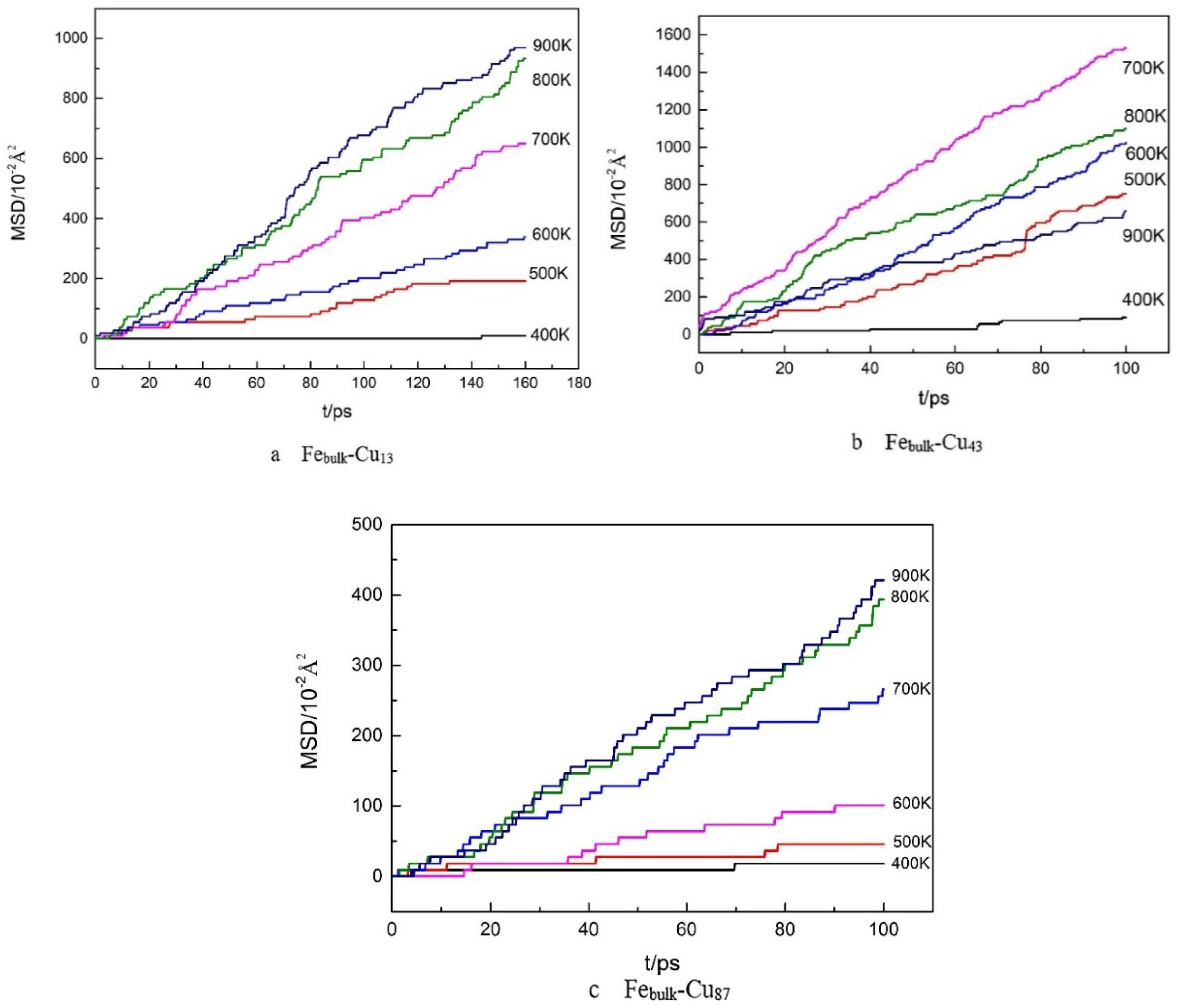
Figure 2 shows the variations of MSDs of Cu atoms in Febulk–Cu13, Febulk–Cu43 and Febulk–Cu87 with the simulation time at different temperatures. For all mean square displacements, only when an atom displacement exceeded the set threshold, was displacement value included in calculations. The threshold value was 1.07374 × 10⁻⁹ so that only when atomic positions presented significant changes would MSDs apparently increase, to avoid the displacements caused by atomic thermal motions. For the Febulk–Cu13 system, there are 54,004 atoms, in which the numbers of Fe and Cu atoms is 53,991 and 13, respectively. Due to the fact that the atomic radius of a Cu atom is slightly greater than that of an Fe atom, when thirteen Cu atoms are in Febulk, these Cu atoms undergo strong constraints from surrounding Fe atoms, which limits the Cu atom mobility greatly. As shown in Figure 2a, when the temperature is 400 K, there are not obvious changes in the positions of Cu atoms. If these Cu atoms are considered as a whole, the packing structures of the Cu13 cluster do not change. When the temperature increases to 500 K, the MSDs increase significantly. It can be found that the increases in the MSDs are not very large, and after a certain time, the MSDs enter a plateau. This suggests that at this temperature, only a small number of atoms change their positions compared to those at 400 K. Above 800 K, the MSDs present increased behavior, implying that the Cu atoms continuously adjust their positions. As for the Febulk–Cu43 system in Figure 2b, the numbers of Fe atoms and Cu atoms are 53,911 and 43, respectively. Because these Cu atoms have a larger moving range than those in the Cu13 case, at 400 K there are apparent increases in the MSDs. At the other temperatures, the MSDs present increased behavior as the simulation time increases. It can be noted that at 800 K and 900 K, the values of the MSDs are lower than at 700 K. This is due to the interaction among the Cu atoms and the atoms in the Febulk. When the Cu atoms adjust their positions, some Fe atoms present position changes. At high temperatures of 800 K or 900 K, some Cu atoms occupy the BCC lattice positions, and they do not change their positions. For the Febulk–Cu87, it can be seen in Figure 2c that the MSDs at 400 K imply that the mobility of the Cu atoms is limited. As the temperature increases above 600 K, the increases in the MSDs suggest continuous adjustments of the atomic positions. In these figures, it can be seen that there are stepped increases for the MSDs. This is because a threshold is set during calculations. When the MSD value at each step is greater than the threshold, this value is included in the total value. Otherwise, this value is considered to be due to lattice vibration.
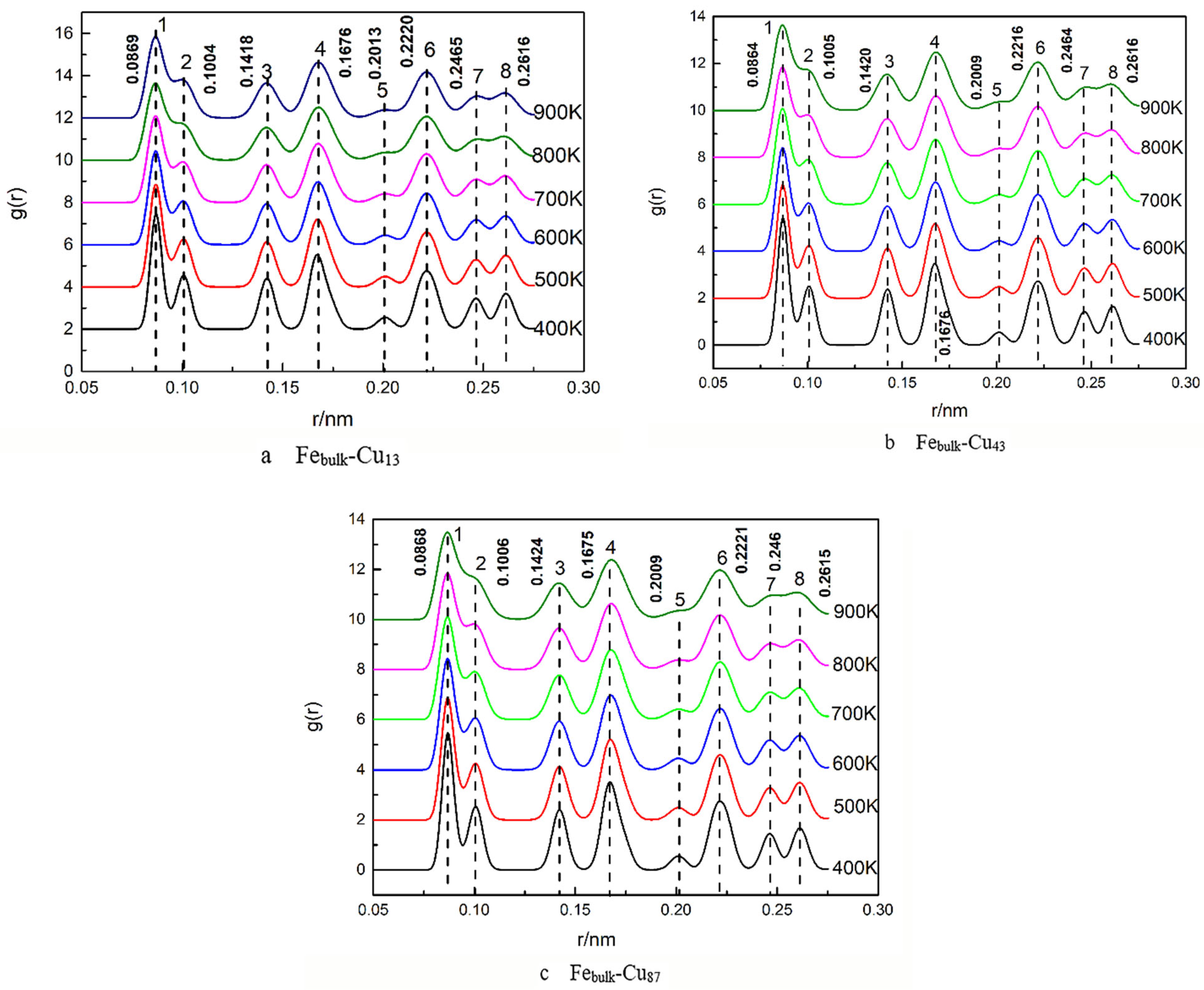
Figure 3 shows PDFs of the three Cu clusters at different temperatures. For the Febulk-Cu13 as shown in Figure 3a, there are distinct peaks at the positions of 0.0869, 0.1004, 0.1418, 0.1665, 0.2013, 0.2220, 0.2465 and 0.2616 nm at 400 K. With the increase in the temperature, the height of these peaks become low, and they widen. However, at 800 K, some peaks disappear, implying changes in the atomic packing of these Cu atoms. For the cases of Febulk–Cu43 and Febulk–Cu87, shown in Figure 3b,c, the PDFs also indicate that only at high temperatures, are there a few atoms adjusting their positions.
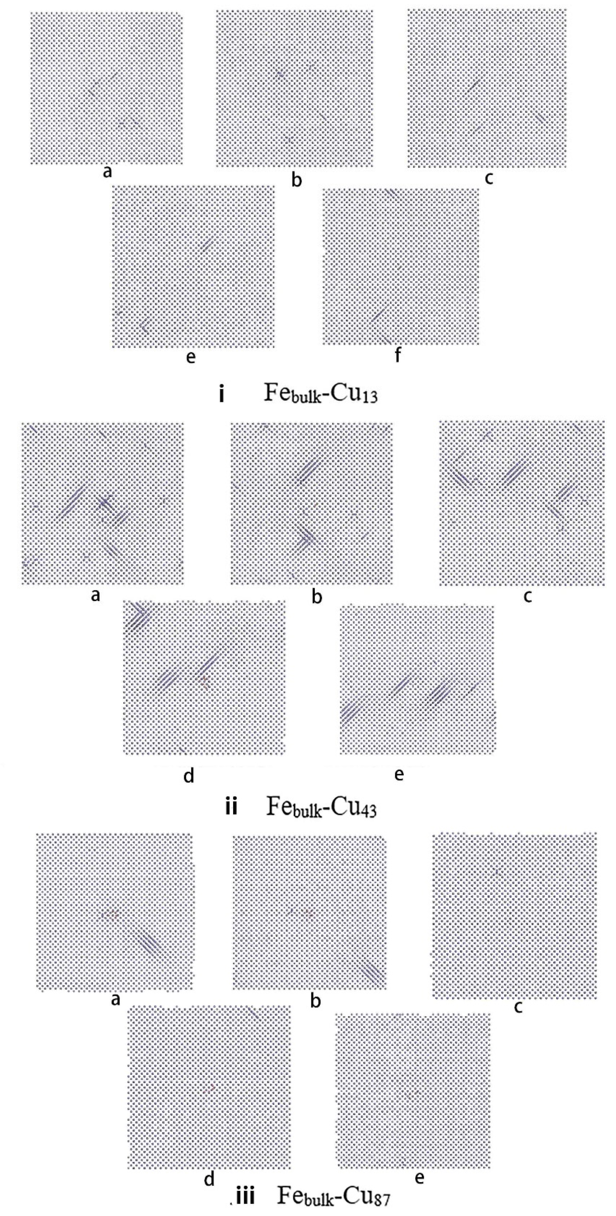
Figure 4 shows the atomic packing of these three Cu clusters at 400, 500, 600, 800 and 900 K along the (001) direction. For the Cu13 cluster, as shown in Figure 4i, below 800 K, the thirteen atoms are at BCC lattice positions. Only at 900 K, one Cu atom leaves the lattice position. Because the radius of Cu atoms is only slightly larger than that of Fe atoms, when these Cu atoms are in the Febulk, they are strongly constrained by the surrounding Fe atoms, which greatly limits the mobility of the Cu atoms. In the case of the Cu43 cluster, as shown in Figure 4ii, at 400 K these Cu atoms are at BCC lattice positions. As the temperature increases, a few Cu atoms adjust their positions. At 800 K, it can be seen that a certain number of atoms are not at lattice positions. Correspondingly, the peak shape of the PDF presents different features from those at low temperature, including lower peak height and increased width. For the Cu87 cluster, as shown in Figure 4iii, at 400 K, when most of the Cu atoms are at BCC lattice positions, a small number of atoms present movements contributing to the small increase in MSDs. At 600 K, all atoms are at lattice positions. As the temperature increases further, a few of atoms adjust their positions, resulting in the increases in the MSDs.
When the Cu clusters change their configurations as the temperature increases, the Fe atoms in bulk present different features. As shown the Febulk in Figure 5i, at 400 K, there are some small strain zones. With the temperature increasing, positions and number of the strain zones changes. However, because there is a small number of Cu atoms at the BCC lattice positions, this small Cu13 cluster does not affect the whole structure of the Febulk. For the Cu43 cluster, as shown in Figure 5ii, a certain number of strain zones appear in the Febulk, and some of them are relatively large. As the temperature increases, the areas of some strain zones decrease significantly, whereas a few of zones grow large. In the meantime, segregation of solute atoms along the direction in (110) occurs. As the atom number of Cu reaches 87, shown in Figure 5iii, one large size strain zone appears in the Febulk, and is adjacent to the Cu clusters, where the positions of the atoms are not at the lattice positions. When the temperature increased to 800 K, the strain zones in the Febulk decreased significantly. At higher temperature, apparent strain in the Febulk disappears.
Figure 6 shows the atomic packing structures in the four sub-regions a-d at 800 K in the Febulk–Cu43 system along the radial direction from the matrix center. As shown in this figure, only Fe atoms exist in region d, while Fe and Cu atoms exist in regions a, b and c. Thus, for this system, it can be clearly seen that there will be vacancies in the Cu clusters and the substitution of Fe and Cu atoms occurs in the simulation process.

4. Conclusions

Atomic simulations within the frame of the embedded atom method were performed to study atomic packing changes of small sized Cu clusters in Febulk on heating by using molecular dynamics. The simulation results show that the size of the Cu clusters in the Febulk apparently affects the atomic packing of the Cu atoms and the structure of the Febulk at different temperatures, the Cu clusters changed from ordered to disordered. The study of three different nano-sized Cu clusters in the Febulk with different temperatures shows that the structure does not increase with the number of atoms in different stacking structures of Cun (n = 13, 43 and 87) clusters. For Febulk–Cu13, a small number of Cu atoms at BCC lattice positions cannot influence the whole structure of the Fe–Cu system. In the Febulk–Cu43 system, although the atomic number increases and the accommodating space in the Febulk becomes greater, most of the Cu atoms are at the BCC lattice positions. As the temperature increases, packing patterns of the Cu atoms change. In the meantime, when most of the areas of the strain zones decrease significantly in Febulk, a few of the strain zones become large, this condition results in an increase in strain within the bulk. In Febulk–Cu87, the position change of these Cu atoms occurs mainly in the interior of the cluster. While the Cu atoms are constrained by the Fe atoms in the bulk, only a few of Cu atoms adjust their positions. With increasing the temperature rise, the strain in the Fe has eased. Thus, the annealing at high temperature can greatly improve the apparent position adjustments among the Cu and Fe atoms, resulting in the obvious changes of the strain in the whole matrix.

Author Contributions

Conceptualization, P.Y., L.Z., L.D.; methodology, P.Y., L.Z.; investigation, P.Y., L.Z.; project administration, P.Y., L.Z.; funding acquisition, L.Z., L.D. All authors have read and agreed to the published version of the manuscript.

Funding

Project supported by National Natural Science Foundation of China (Grant No. 51671051).

Institutional Review Board Statement

Not applicable.

Informed Consent Statement

Not applicable.

Data Availability Statement

Not applicable.

Conflicts of Interest

The authors declare no conflict of interest.

References

  1. Wasserman, G.; Wincierz, P. Einfluß von Abschreckspannungen auf die Änderung der Gitterkonstanten bei der Aushärtung von Eisen-Kupfer-Legierungen. Arch. Eisenheuuenw 1958, 29, 310. [Google Scholar] [CrossRef]
  2. Murayama, M.; Katayama, Y.; Hono, K. Microstructural Evolution in a 17-4 PH Stainless Steel after Aging at 400 °C. Metall. Mater. Trans. A 1999, 30, 345–353. [Google Scholar] [CrossRef]
  3. Yang, W.D. Reactor Materials, 2nd ed.; Atom Energy Pres: Beijing, China, 2006. [Google Scholar]
  4. Qian, G.; González-Albuixech, V.F.; Niffenegger, M. Comparison of K1 calculation methods. J. Nucl. Eng. Des. 2014, 270, 312. [Google Scholar] [CrossRef]
  5. Ortiz, C.J.; Caturla, M.J. Cascade damage evolution: Rate theory versus kinetic Monte Carlo simulations. J. Comput. Aided Mater. Des. 2007, 14, 171–181. [Google Scholar] [CrossRef]
  6. Ortiz, C.J.; Caturla, M.J.; Fu, C.C.; Willaime, F. Nucleation and Growth of Defects in He irradiated Fe using Rate Theory and Kinetic Monte Carlo Methods. Mrs Online Proceeding Libr. 2011, 908. [Google Scholar] [CrossRef]
  7. Gámez, L.; Martinez, E.; Perlado, J.M.; Cepas, P.; Caturla, M.J.; Victoria, M.; Marian, J.; Arévalo, C.; Hernández, M.; Gómez, D. Kinetic Monte Carlo modelling of neutron irradiation damage in iron. Fusion Eng. Des. 2007, 82, 2666–2670. [Google Scholar] [CrossRef]
  8. Sato, A.; Meshii, M. Recovery of irradiation-induced defects in high-purity iron and iron–carbon solid solutions. Phys. Status Solidi 1974, 22, 253–260. [Google Scholar] [CrossRef]
  9. Takaki, S.; Fuss, J.; Kuglers, H.; Dedek, U.; Schultz, H. The resistivity recovery of high purity and carbon doped iron following low temperature electron irradiation. Radiat. Effects 2006, 79, 87–122. [Google Scholar] [CrossRef]
  10. Miller, M.K.; Russell, K.F.; Sokolov, M.A.; Nanstad, R.K. APT characterization of irradiated high nickel RPV steels. J. Nucl. Mater. 2007, 361, 248. [Google Scholar] [CrossRef]
  11. Fujii, K.; Fukuya, K.; Nakata, N.; Hono, K.; Nagai, Y.; Hasegawa, M. Hardening and microstructural evolution in A533B steels under high-dose electron irradiation. J. Nucl. Mater. 2005, 340, 247058. [Google Scholar] [CrossRef]
  12. Miller, M.K.; Russell, K.F. Embrittlement of RPV steels: An atom probe tomography perspective. J. Nucl. Mater. 2007, 371, 145. [Google Scholar] [CrossRef]
  13. Jiang, J.; Wu, Y.C.; Liu, X.B.; Wang, R.S.; Nagai, Y.; Inoue, K.; Shimizu, Y.; Toyama, T. Microstructural evolution of RPV steels under proton and ion irradiation studied by positron annihilation spectroscopy. J. Nucl. Mater. 2015, 458, 326–334. [Google Scholar] [CrossRef]
  14. Ardekani, S.F.G.; Hadad, K. Monte Carlo evaluation of neutron irradiation damage to the VVER-1000 RPV. Nucl. Energy Technol. 2017, 3, 73–80. [Google Scholar] [CrossRef]
  15. Nie, J.; Liu, Y.; Xie, Q.; Liu, Z. Study on the irradiation effect of mechanical properties of RPV steels using crystal plasticity model. Nucl. Eng. Technol. 2019, 51, 501–509. [Google Scholar] [CrossRef]
  16. Xu, G.; Cai, L. Study On the precipitation of cu–rich clusters in the RPV model steel by APT. Acta Metall. Sin. 2012, 48, 407–413. [Google Scholar] [CrossRef]
  17. Wang, W.; Zhou, B. Precipitation and Structural Evolution of Copper-Rich Nano Phases in Reactor Pressure Vessel Model Steels; School of Shanghai University: Shanghai, China, 2011. [Google Scholar]
  18. Hu, S.Y.; Li, Y.L.; Watanabe, K. Calculation of internal stresses around Cu precipitates in the bcc Febulk by atomic simulation. Model. Simul. Mater. Sci. Eng. 1999, 7, 641–655. [Google Scholar] [CrossRef]
  19. Monzen, R.; Jenkins, M.L.; Sutton, A.P. The bcc-to-9R martensitic transformation of Cu precipitates and the relaxation of elastic strains in an Fe-Cu alloy. Philos. Mag. A 2000, 80, 711–723. [Google Scholar] [CrossRef]
  20. Lee, T.H.; Kim, Y.O.; Kim, S.J. Crystallographic model for bcc-to-9R martensitic transformation of Cu precipitates in ferritic steel. Philos. Mag. 2007, 87, 209–224. [Google Scholar] [CrossRef]
  21. Becquart, C.S.; Domain, C. Solute–point defect interactions in bcc systems: Focus on first principles modelling in W and RPV steels. Curr. Opin. Solid State Mater. Sci. 2012, 16, 115–125. [Google Scholar] [CrossRef]
  22. Mendelev, M.I.; Han, A.; Srolovitz, D.J.; Ackland, G.J.; Sun, D.Y.; Asta, M. Asta.Development of new interatomic potentials appropriate for crystalline and liquid iron. Philos. Mag. A 2003, 83, 3977. [Google Scholar] [CrossRef]
  23. Mishin, Y.; Mehl, M.J.; Papaconstantopoulos, D.A.; Voter, A.F.; Kress, J.D. Structural stability and lattice defects in copper: Ab initio, tight-binding, and embedded-atom calculations. Phys. Rev. B 2001, 63, 224106. [Google Scholar] [CrossRef] [Green Version]
  24. Voter, A.F.; Chen, S.P. Accurate Interatomic Potentials for Ni, Al and Ni3Al.Mater. Res. Soc. Symp. Proc. 1987, 82, 175. [Google Scholar] [CrossRef]
  25. Pasianot, R.C.; Malerba, L. Interatomic potentials consistent with thermodynamics: The Fe–Cu system. Nucl. Mater. 2007, 360, 118. [Google Scholar] [CrossRef]
  26. Bonny, G.; Pasianot, R.C.; Malerba, L. Fitting interatomic potentials consistent with thermodynamics: Fe, Cu, Ni and their alloys. J. Philos. Mag. 2009, 89, 3451–3464. [Google Scholar] [CrossRef]
  27. Bonny, G.; Pasianot, R.C.; Castin, N.; Malerba, L. Ternary Fe-Cu-Ni many-body potential to model reactor pressure vessel steels: First validation by simulated thermal annealing. Philog. Mag. 2009, 89, 3531–3546. [Google Scholar] [CrossRef]
  28. Cai, L.; Xu, G. Deformation Characterization of Nano-Scale Cu-Rich Precipitates in Reactor Pressure Vessel Model Steel. J. Shanghai Univ. 2012, 18, 311–316. [Google Scholar]
  29. Fujii, K.; Fukuya, K. Characterization of defect clusters in ion-irradiated A533B steel. Nucl. Mater. 2005, 336, 323–330. [Google Scholar] [CrossRef]
  30. Ackland, G.J.; Bacon, D.J.; Calder, A.F.; Harry, T. Computer simulation of point defect properties in dilute Fe—Cu alloy using a many-body interatomic potential. Philos. Mag. A 1997, 75, 713–732. [Google Scholar] [CrossRef]
  31. Domain, C.; Becquart, C.S. Computer simulation of point defect properties in dilute Fe—Cu alloy using a many-body interatomic potential. Phys. Rev. B 2001, 65, 024103. [Google Scholar] [CrossRef]
  32. Shu, X.; Li, X. Fe self-diffusion and Cu and Ni diffusion in bulk and grain boundary of Fe: A molecular dynamics study. Nucl. Instrum. Methods Phys. Res. B 2013, 307, 37–39. [Google Scholar] [CrossRef]
  33. Messina, L.; Chiapetto, M. An object kinetic Monte Carlo model for the microstructure evolution of neutron-irradiated reactor pressure vessel steels. Phys. Status Solidi A 2016, 213, 2974–2980. [Google Scholar] [CrossRef]
  34. Bonny, G.; Pasianot, R.C.; Malerba, L. Fe–Ni many-body potential for metallurgical applications. Simul. Mater. Sci. Eng. 2009, 17, 025010. [Google Scholar] [CrossRef]
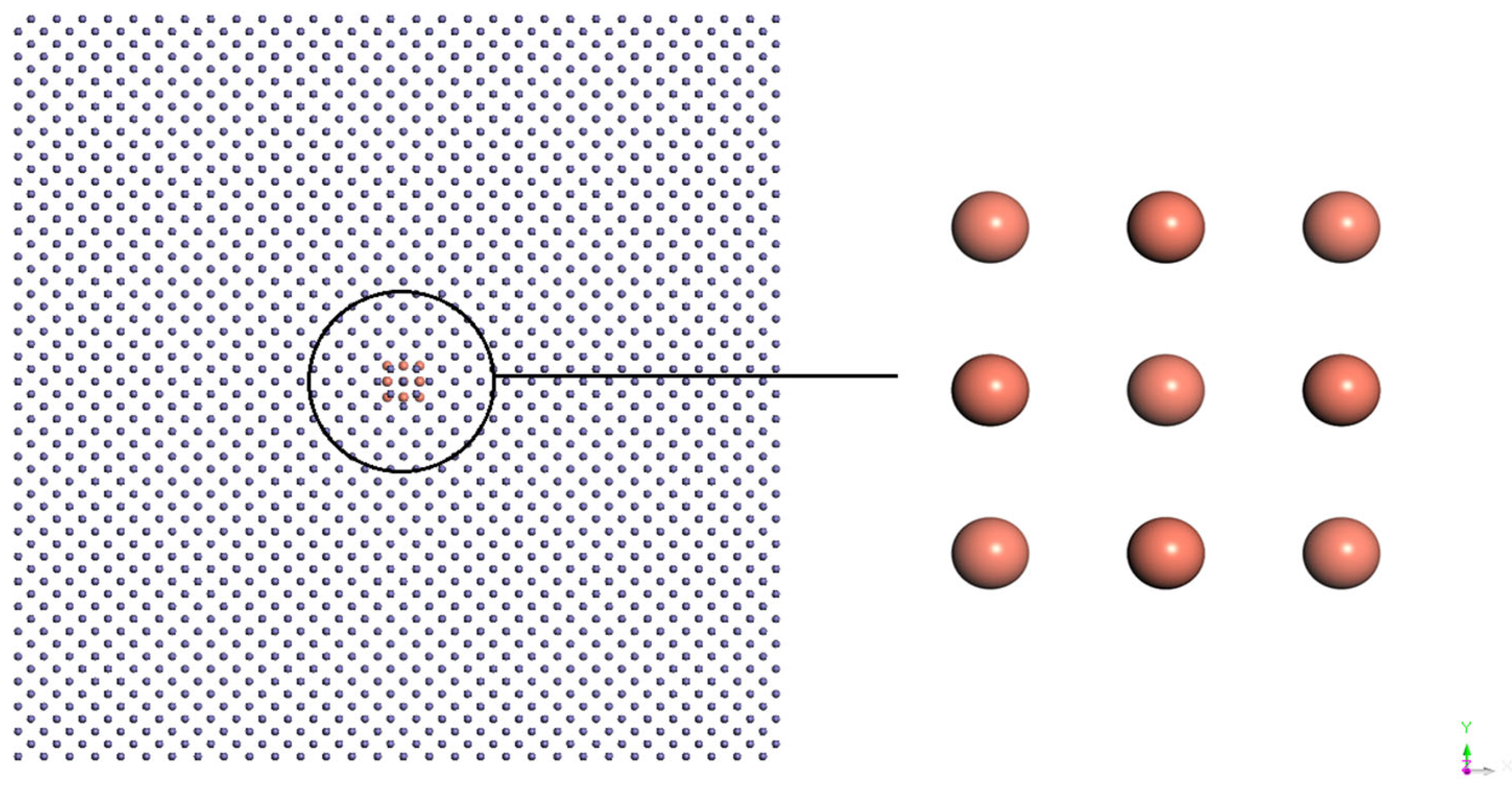
Figure 1. Three-dimensional projection of the Febulk–Cu13 binary system.
Metals 11 00934 g001
Figure 2. Mean square displacements of Cu atoms in Febulk–Cun, n = 13 (a), 43 (b) and 87 (c).
Metals 11 00934 g002
Figure 3. Pair distribution function curve of Cu atoms in Febulk–Cun systems, n = 13 (a), 43 (b) and 87 (c).
Metals 11 00934 g003
Figure 4. 2d projection of Cu cluster in the Febulk–Cun system, n = 13 (i), 43 (ii) and 87 (iii) at a given temperature. (a) 400 K; (b) 500 K; (c) 600 K; (d) 800 K; (e) 900 K.
Metals 11 00934 g004
Figure 5. Two-dimensional projection of the Febulk–Cun system, n = 13 (i), 43 (ii) and 87 (iii): (a) 400 K; (b) 500 K; (c)600 K; (d) 800 K; (e) 900 K.
Metals 11 00934 g005
Figure 6. Atomic packing structures in four sub-regions (ad) along the radial direction from the matrix center at 800 K for Febulk–Cu43.
Metals 11 00934 g006
Publisher’s Note: MDPI stays neutral with regard to jurisdictional claims in published maps and institutional affiliations.