Review

Analysis of the Advantages of Laser Processing of Aerospace Materials Using Diffractive Optics

by
Serguei P. Murzin
1,2,*,
Nikolay L. Kazanskiy
1,3 and
Christian Stiglbrunner
2
1
Samara National Research University, Moskovskoe Shosse 34, 443086 Samara, Russia
2
TU Wien, Institute of Production Engineering and Photonic Technologies, Getreidemarkt 9, 1060 Vienna, Austria
3
IPSI RAS—Branch of the FSRC «Crystallography and Photonics» RAS, Molodogvardejskaya Street 151, 443001 Samara, Russia
*
Author to whom correspondence should be addressed.
Metals 2021, 11(6), 963; https://doi.org/10.3390/met11060963
Submission received: 19 May 2021 / Revised: 5 June 2021 / Accepted: 10 June 2021 / Published: 15 June 2021
(This article belongs to the Special Issue Laser Treatment of Metals and Alloys)

Abstract

:
We considered possibilities of an application of diffractive free-form optics in laser processing of metallic materials in aerospace production. Based on the solution of the inverse problem of heat conduction, an algorithm was developed that calculates the spatial distribution of the power density of laser irradiation in order to create the required thermal effect in materials. It was found that the use of diffractive optics for the laser beam shaping made it possible to obtain specified properties of processed materials. Laser thermal hardening of parts made of chrome–nickel–molybdenum steel was performed. This allowed us to increase the wear resistance due to the creation in the surface layer of a structure that has an increased hardness. In addition, a method of laser annealing of sheet materials from aluminum–magnesium alloy and low-alloy titanium alloys was developed. Application of this method has opened opportunities for expanding the forming options of these materials and for improving the precision in the manufacturing of aircraft engine parts. It was also shown that welding by a pulsed laser beam with a redistribution of power and energy density makes it possible to increase the strength of the welded joint of a heat-resistant nickel-based superalloy. Increasing the adhesion strength of gas turbine engine parts became possible by laser treatment using diffractive free-form optics.

1. Introduction

Structural materials and components used in the aerospace industry are subjected to extraordinarily harsh conditions during their service life. These include an extremely wide range of operating temperatures and great mechanical loads. As the high specific strength is obviously another prerequisite, the applicable materials are limited to high-strength steels, nickel-based superalloys, and titanium alloys [1,2,3]. The important characteristics, including durability, ductility, hardness, and toughness, are largely determined by the internal structure of the materials. Control over these characteristics can be exercised by determining the grain size, number and position of lattice defects, impurities, and other substructural units, which requires the appropriate kind and localization of thermal treatment [4,5,6]. The unrivalled and most versatile tool for executing such a treatment is the laser, which is capable of various processing methods and transferring (inducing) precisely defined amounts of energy to confined or hardly accessible regions, all the while avoiding contact and causing vibrations [7,8,9].
Implementing and making purposeful use of a selected method of laser processing require us to irradiate predefined areas of the material with an adequate and accurately defined distribution of power density [10,11]. So far, practical solutions using various optical systems satisfy this demanding requirement only to a certain degree, leaving the range of possibilities rather poorly exploited. In principle, any surface of an optical element capable of focusing the laser beam in the needed way can be calculated. Unfortunately, this does not mean such a surface can be manufactured. Optical elements with surfaces deviating from the calculated shape are prone to causing various kinds of defects during laser processing. Consequently, these do not provide the necessary control over the desired specific modifications or changes in local areas. The current solution to this problem is simple evasion of the use of the type of materials that react with a higher degree of sensitivity to thermal changes. This approach is ineffective, and the possibilities of laser processing are not fully exploited.
For the shaping of laser beams, different methods characterized by design variations in optical systems were developed [12,13,14]. However, not all potential material processing possibilities have been exhausted or realized. Therefore, in parallel with the development of laser techniques, the technology of beam shaping has also progressed. For cutting, marking, engraving, and drilling, simple objectives can sometimes be used; for example, single lens objectives, one objective with two or three spherical or parabolic lenses, or a single spherical mirror [15,16]. However, that is often not sufficient to focus a beam onto a predetermined area of the workpiece. Except for some particular cases, neither one of the existing optical systems for laser processing on zones of a predefined shape can provide a simultaneous combination of such functional capabilities as generating the required distribution of the power density and the concentration of all of the energy of the laser beam into the processing zone of a desired shape with high reliability. Figure 1a shows the geometry of the focusing of a laser beam with the complex amplitude F0 into a section |x| ≤ d in the focal plane z = f [17]. The aperture of the optical element G is restricted by the curves v = g1 (u) and v = g2 (u) and by sections of straight lines u = a and u = b. The function µ (x, ε) characterizing the distribution of energy in the ε-vicinity of the focusing section is introduced.
The use of optical elements with surfaces that have even a small deviation from the calculated one can lead to the formation of various defects during the processing phase. Examples include burning, a coarse-grained structure, local melts, and shape distortions of sheet metal blanks due to uneven heat development across the width of the heat-affected zone. The following defects, including those presented in Figure 1b,c [18], are also characteristic: an uneven processing depth as well as an uneven distribution of mechanical properties across the width of the heat-affected zone, including an insufficient hardness of some areas due to heating below the targeted temperature. These defects can be only prevented by preliminarily selecting materials with a wider temperature range of the desired structural change. This is very inefficient because, in this case, the performance properties will not be improved as significantly as they could be. That means that the applied optical systems do not allow for the usage of all available advantages of laser treatment.
Instead of applying optical elements not specifically harmonizing with the task, a more recent approach utilizes diffractive free-form optics to control the power density distribution of the laser beam more precisely. Early scientific investigations regarding the basics of applying computer-synthesized diffractive optical elements to laser processing have already been carried out and published [19,20,21,22]. Sufficient attention has been paid to the development and application of special optical systems for laser beam shaping in order to accurately distribute the power density. However, investigations on the effect of a laser beam on materials in relation to the resulting power density in aerospace manufacturing have been limited. Therefore, only a small number of publications have been devoted to improving the physical and mechanical properties using laser irradiation with a predetermined power density distribution.
The main purpose of this article is to provide systematized information on the advantages of using diffractive free-form optics that are designed based on the calculation of the power density distribution of the beam for the creation a desired thermal effect during laser processing of metal materials that are applied in aerospace manufacturing.

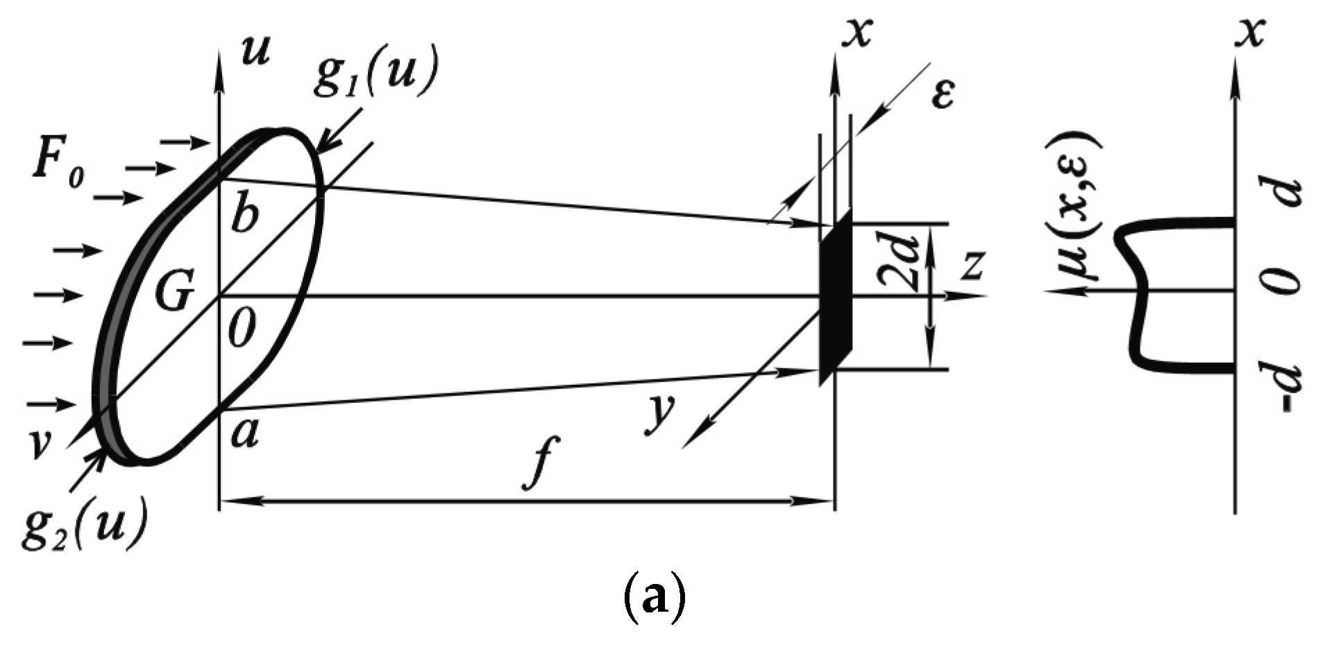
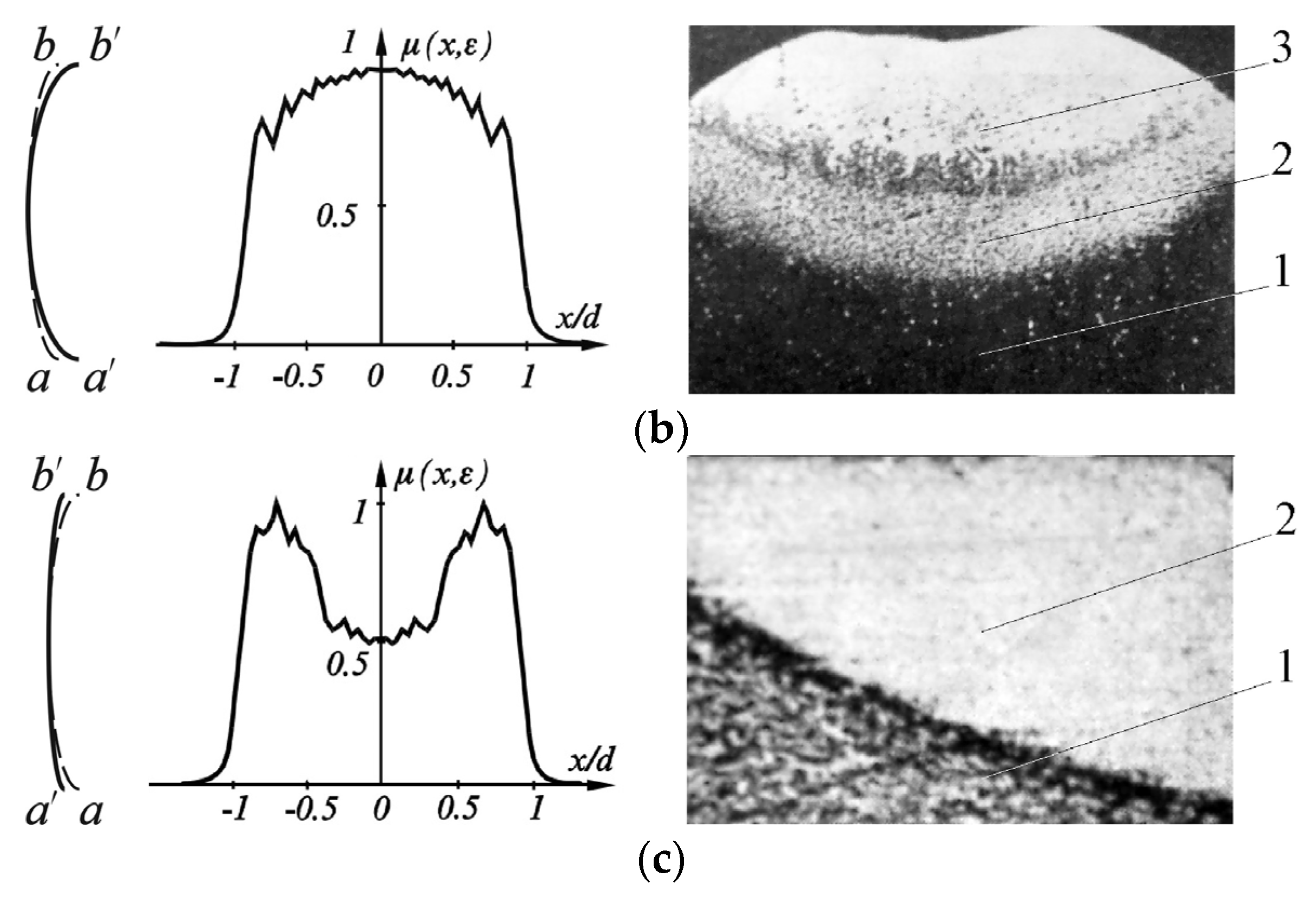
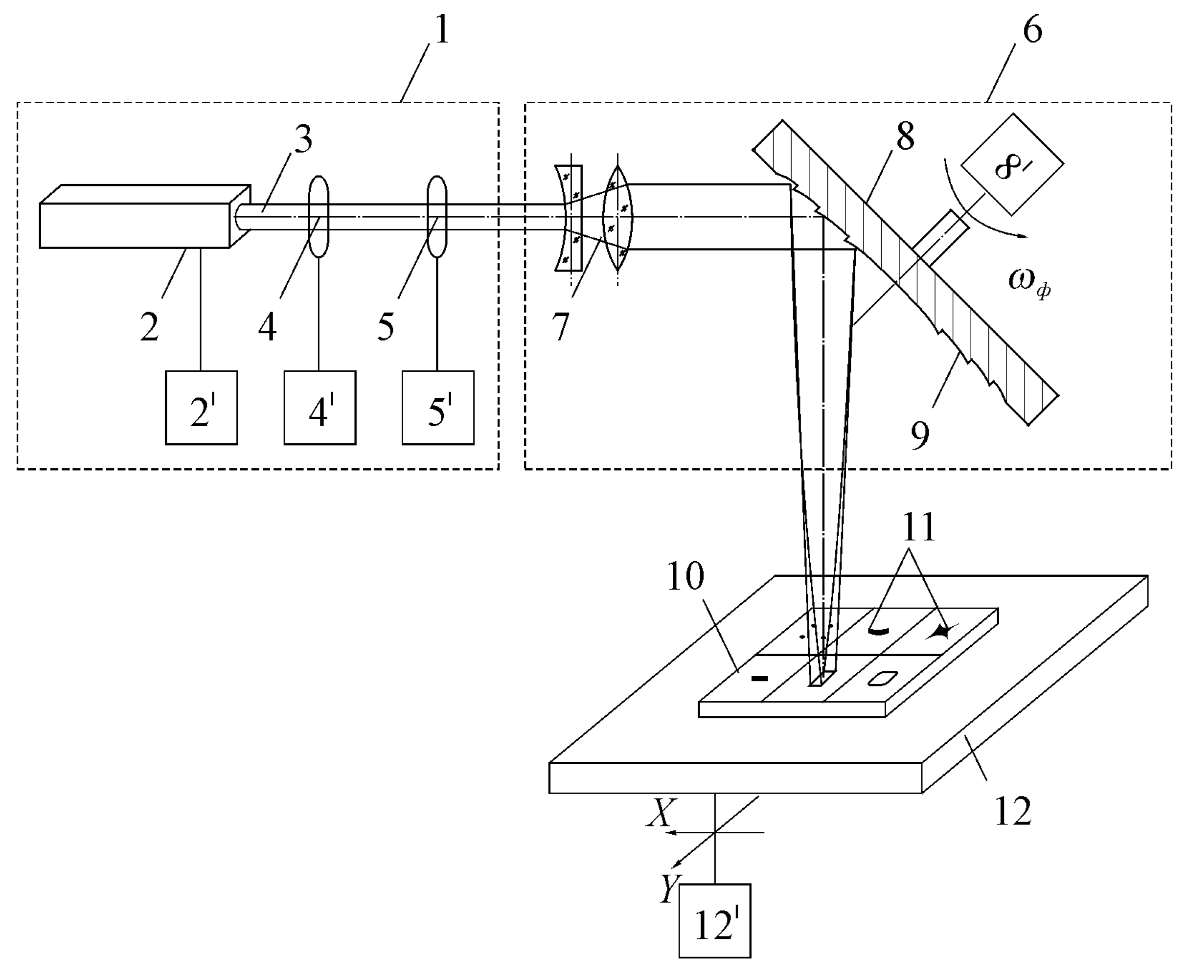
2. Optical Systems for the Shaping of Laser Beams

Laser irradiation permits the creation of the high densities of heat flow in a small surface area necessary for intense heating or melting of metallic materials [23,24,25]. The occurring effects of the interaction between the beam and the metal depend on the ratio of exposure time to relaxation time, as well as on the power density of the laser beam during processing of alloys [26,27,28]. Phase transformations confined to micro volumes can be explained by the known state diagrams of these alloys. Laser heat treatment methods are similar to conventional methods for the thermal treatment of alloys and include laser hardening, annealing, and tempering. The desired properties of the material are created by an adequate change in the thermal state of the targeted spots in the material during laser irradiation [29,30]. The nature of the thermal processes is determined by the beam characteristics (power density, distribution of the power density over the beam cross section, and exposure time) as well as geometric parameters. Theoretical prediction of thermal processes allows us to formulate the basic requirements for the parameters of the laser irradiation in order to improve efficiency. The increasing capabilities of computing tools justify the widespread use of numerical methods for solving the most complex tasks of laser heating, including unsteady three-dimensional problems of nonlinear thermal conductivity [31,32].
A characteristic feature of laser treatment in the range of power level densities applied is that layer boundaries of zones of structural changes are practically located along the lines of isotherms. These actually illustrate the temperature field, in this way showing the temperature distribution in the heat-affected zone. Studies of the thermal state of the surface layers of materials subjected to laser irradiation can be found in [33,34,35,36]. They show that the characteristics of the temperature field in materials (the value and gradient of temperatures, heating and cooling rates) are greatly influenced by beam parameters, the movement speed of the heat source, the power density distribution of the beam, thermal and physical characteristics, and the size of the processed objects.
In order to increase the width of the heat treatment zone, in [37,38] the recommendation can be found to perform multiple passes of the laser beam with overlapping zones. During processing, the laser irradiation zones are superimposed on each other, which causes unproductive energy losses due to laser pulses being spent on the re-heating of already treated areas [39,40]. When processing with overlapping of heat-affected zones, layers significantly differing in micro-hardness are obtained. This kind of thermal influence on materials is generally undesirable. It conflicts with the high requirements for uniformity in the depth of the treatment zone and the physical and mechanical properties of the material [41,42]. As optimizing productivity, when pulse treating along a contour, tends to increase the step size, the uniformity is further jeopardized. Still, it has to be ensured that the required properties are not sacrificed by the treatment. To solve these tasks, it was necessary to develop special optical systems for laser beam shaping. Such systems are described in detail in [43,44]. Table 1 lists different optical systems that are currently used for laser beam shaping with an intensity redistribution [43].
In principle, the surface shape of the optical element can be calculated by solving the inverse problem of focusing [45]. Although we can calculate such surfaces, it is not currently possible to manufacture any such surface by modern technical means. Recently [45,46], free-form optics have been introduced for adapted beam shaping in laser heat treatment. Intensity distributions that induce previously defined temporal and spatial temperature profiles are generated by them. As shown in [47,48], both the calculation and manufacture of optical elements that form a complex narrow-angle light distribution using total internal reflection surfaces are quite complicated tasks. Currently, there are no general methods for building a ray tracing function for an arbitrary region. Furthermore, when creating complex beam distributions, the inverse problem of surface shape determination frequently cannot be solved due to violation of the integrability condition. In addition, to fabricate the mirror using the available set of milling cutters, the reflective surface is smoothed by rational B-splines. So, the radius of the normal curvature of the surface arrives at a certain value [49]. According to [50], subsequent to special corrective machining for intensity tailoring, the shape error of free-form mirrors could reach up to 200 nm. Such errors might decrease the quality of the shaped irradiance distribution.
In this case, in order to focus the monochromatic beam, it is advisable to perform a phase modulation of the wavefront [51]. It is performed depending on the phase and intensity of the focusable beam and a predetermined power density distribution over the focusing area. An accordance between the points of the wavefront of the focusable beam and the points of the focusing area is maintained. A high monochromaticity and a long coherence length of the laser beam enable the use of diffractive free-form optics for its shaping. The characteristic heights of the microrelief of the diffractive optical elements correspond to the order of the radiation wavelength. Such optical elements for a given complex beam focusing can be produced by various methods [52,53,54]. Due to the flexibility of computer designs and the capabilities of modern precision technologies to create a microrelief, we obtain a unique optical tool for the required control of the wavefront or for the predefined shaping of laser beams.
The laser system [21] (Figure 2) contains the laser beam source 1 on the optical axis, and there is the optical system 6 for shaping the laser beam and transporting it to the material under the process 10. The optical system contains at least one computer-generated diffractive optical element (diffractive free-form optics) 8. The optical element is made in the form of a reflective or transmissive plate with a micro-textured surface structure, determined depending on the shape of the treatment zone 11, the distribution of the power density and energy of the laser beam and its wavelength, with the possibility of rotation by a predetermined angle or rotation with an angular velocity ωφ.

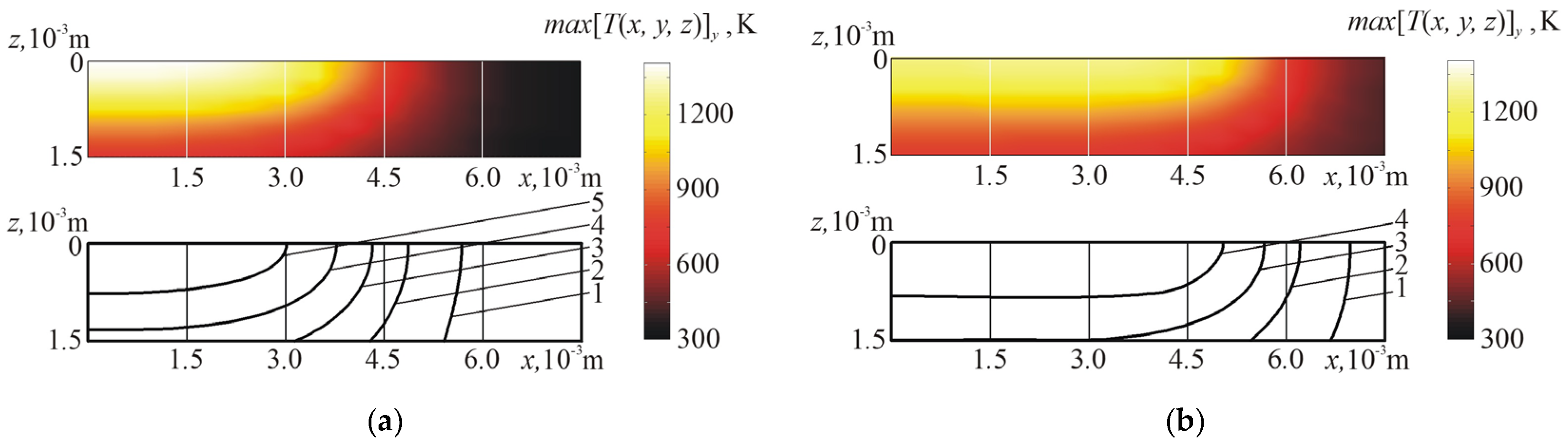
3. Calculation of the Power Density Distribution of the Laser Beam to Create a Desired Thermal Effect in Materials

During processing of metallic materials by a laser beam, the absorption characteristics cause only some of the incident energy to lead to the formation of a surface heat source, which also depends on the beam power and spatio-temporal parameters. The generated heat propagates into the material. The temperature dependencies of optical and thermophysical coefficients are the cause of nonlinearities in the mathematical description of laser beam heating. Therefore, most often it is necessary to use numerical methods to determine the temperature [55], which does not exclude solutions reached by approximate analytical methods in some cases.
The study of thermal processes allows us to identify common relations and the main areas for the improvement of processes to initiate concentrated energy flows. Lasers’ effects on opaque materials in a wide range of power densities, of up to 1013 W/m2, are satisfactorily described by the thermal model [56,57]. Material properties depend on the thermal state. The nature of thermal processes is determined by the thermophysical characteristics of processed materials (e.g., thermal conductivity, specific heat capacity, surface heat transfer coefficient), laser-beam parameters (e.g., power density, cross-sectional intensity distribution, spot geometry), and beam exposure time. Meaningful results can be obtained by analytical methods, but these tend to be limited by the assumption made to arrive at a particular solution [58,59]. As a result, quite often these results deviate from the real situation of a practical problem. These restrictions can be relaxed significantly in a numerical approach. Temperature-dependent thermophysical properties, the spatial distribution of heat sources, radiative and convective heat losses, and the latent heat of a phase transition can all be taken into account. The numerical solutions can be obtained either by the finite element method or by the finite difference method.
The solution of the inverse problem of non-stationary heat conduction provides us with an opportunity to determine the specific heat flow through the surface of the studied object, provided that the mathematical model, the temperature field, and the coefficients needed for the main equation are known. The direct problem of determining the temperature field at the internal points of the studied object from the known power distribution of the energy flow is well-posed. Its solution satisfies the conditions of resolvability, uniqueness, and stability [60,61]. The second type of boundary condition for the heat equation includes the power density distribution of the applied heat flow. The inverse problem of distribution determination is not always well-posed, because its solution is not always unique and stable. There are approaches to solving ill-posed problems [62] based on narrowing the range of possible solutions using additional assumptions regarding the unknown function. In this case, non-existence and non-uniqueness can usually be overcome by settling for “generalized” solutions, leading to the need to develop regularizing algorithms. The theory of ill-posed problems has advanced greatly since A.N. Tikhonov laid its foundations, but the most common way to solve such problems is the iterative method described in detail in [62]. The condition for the iterations to end is the coincidence of the required accuracy of the specified and obtained temperature values. The condition of constancy in time of the heat flow for a well-posed formulation of the inverse problem of heat conduction for determining the source is satisfied, since after a certain number of iterations the temperature field at interior points of the object will have regularized [62,63].
There are a few publications on the topic of calculation of the power density distribution of the laser beam in order to determine a specific thermal exposure on the treated object. However, these either do not consider the real geometry of samples and the temperature-dependent thermophysical properties of processed materials (e.g., thermal conductivity, specific heat capacity, surface heat transfer coefficient) [64] or are not sufficiently supported by experimental data.
In [65], based on the use of methods for solving the inverse problem of heat conduction presented in [60,61,62,63,64], an algorithm for the calculation of the power density distribution of the laser beam was developed in order to create a desired thermal effect on materials. Using the approaches outlined in [62] for a particular problem, namely heat sources that move with a constant linear or angular velocity on the surface of the material, the maximum tolerable surface temperature was initially determined. Program parameters require us to stipulate an initial polynomial power density distribution, the geometrical depth of the targeted position of the intended structural transformation process, the maximum temperature in that zone, and, finally, the tolerance limit or demanded accuracy. The next step is to calculate a discretization of the power density distribution allocated in a geometrical matrix. Then, the critical value for the linear velocity of the heat source is determined in order to keep the temperature at the surface below or equal to the maximum tolerable temperature. Then, by calculating the resulting temperature in the zone at the target depth, the iterative calculation starts, followed by the determination of the mean square deviation from the demanded temperature. This deviation is compared to the tolerance limit specified as one of the program parameters. As long as the condition of sufficient accuracy is not satisfied, a correction of the power density distribution is implemented into the iterative process. The means of influencing it are modifications in the velocity of the laser spot and realigning the optical element. The new values are entered into the iteration continually until the accuracy criterion is satisfied. Then, the adapted linear velocity and power density distribution are obtained, warranting the desired thermal effect in the targeted zone.
It has been shown that the redistribution of the power density in moving heat sources can adjust the temperature distribution in the treated zone. The results of thermal process calculations show the capability of the developed algorithm to define the parameters that create a more uniform temperature field across the width of the heat-affected zone. More evenly distributed maximum temperature values in the center and the periphery of the heat-affected zone are achieved and a greater width in the required range of temperatures is reached. An improvement in the parameters of the temperature field in chrome–nickel–molybdenum steel for laser heat treatment has been demonstrated. In addition to achieving more uniform temperature conditions across the width of the heat-affected zone, the proposed approach allows us to increase the width of the targeted isotherms of the temperature field. In this way, larger areas per unit of time can be processed at the same laser power, or the number of passes can be reduced. An example of the calculation results of maximum temperature values before and after adaption of the power density is shown in Figure 3.
The structure of 40HNMA chrome–nickel–molybdenum steel (a Russian analogue of 40NiCrMo6 steel) in the cross section of the heat-affected zone after laser heat treatment has also been studied. A preliminary calculation was carried out according to the above-described algorithm presented in [65]. The metallographic analysis of the microstructure of the specimen confirmed the absence of undesirable defects on the object’s surface. The heat influence had created several planar zones, in each of which the microhardness differed from the initial one to varying degrees. The hardest surface layer, with reduced etchability, was the martensite layer. Below this martensitic zone, a region of incomplete hardening with a martensitic and ferritic structure was detected. Further into the material was the transition zone. In the case of laser treatment of thermally hardened steel, this zone shows a reduction in microhardness due to the formation of tempering structures (troostite or sorbate, respectively). The initial structure of the material was a sorbite structure. The formation of such structures in the heat-affected zone is caused by the character of the distribution of temperature fields and the difference in the cooling rate along the depth (Figure 4).
The wear rate of samples of 40HNMA steel was investigated on a special stand in the sliding friction mode according to the friction pattern of a shoe pressed against a rotating disk. Discs from chrome–nickel–molybdenum steel had a diameter of 50 mm and a width of 12 mm. The determination of the amount of wear by weight for the samples was carried out by weighing them on an analytical balance; meanwhile, the configuration of these samples was quite simple. It was established that, in comparison with the treatment with high-frequency currents, the linear wear of the samples of 40HNMA steel decreased by 1.6–1.8 times after laser treatment with the use of diffractive optical elements [65]. After tests, it was revealed that the friction surfaces that had undergone laser heat treatment did not have the network of microcracks typical of specimens quenched by high-frequency currents. At the same time, during the stage of steady-state wear, the wear rate and the coefficient of friction remained stable.

4. Local Laser Annealing of Metallic Sheet Materials

Unlike hardening, laser annealing is used to obtain a structure with a higher degree of equilibrium compared with the initial state [66,67]. This type of structure has greater plasticity and lower hardness. Annealing requires a cooling rate that is significantly lower than the critical rate. The most frequently implemented technique is laser recrystallization annealing of coated or deposited thin films, which is designed to reduce stresses and increase the stability of the material’s structure. Thin film coatings deposited on a substrate in a vacuum or from the gas phase are characterized by the presence of a large number of internal defects. Because of the high cooling rates during application, some of the thin films have an amorphous structure. Subsequent to laser irradiation, the number of defects in the crystal structure decreases, the density increases, and, consequently, the physical and chemical properties change. For example, vacuum-deposited thin film coatings of germanium have a grain size of several tens of nanometers and are characterized by low hole-type conductivity. After laser recrystallization annealing, the grain size increases to several hundred micrometers, and the n-type electronic conductivity in germanium also sharply increases. The reduction in the number of defects in the structure subsequent to laser recrystallization annealing leads to a decrease in electrical resistance. This process is widely used in the electronic industry for adjusting resistors that have not passed through vacuum annealing. In addition, such annealing is used to fabricate contacts and current tracks in semiconductor devices.
Furthermore, laser annealing is applied to decrease the hardness and increase the plasticity of local sections for subsequent deformation [68]. In this way, laser recrystallization annealing is applicable not only for processing semiconductor materials of electronic equipment, but also for treating metal materials. High-speed heating of metallic materials causes the initiation and termination of primary recrystallization to be moved to higher temperatures. This leads to an increase in the number of crystallization centers, a reduction in the recrystallization time, and a decrease in the grain size compared with slow heating. The application of laser heating in combination with other types of metal processing, such as pressure treatment, is of particular importance. Applied in this manner, laser heating permits us to increase the plasticity of local sections of the material. The use of laser annealing can be extraordinarily effective for processing materials such as hard alloys, heat-resistant steels and alloys, and hardened or work-hardened alloys [69,70].
In the leading, most technically advanced branches, such as power mechanical engineering and the aerospace industry, up to 20% of the mass of manufactured articles in the category of the highest complexity is accounted for by workpieces from sheet material. Their labor intensity in production is around 15% of the total of a manufactured product [71]. For example, body parts that determine the relative position of components of the product have a thin-wall structure with various recesses, stiffening ribs, etc. Despite the variety of body shapes, sizes, and materials, these have common technical features, such as tight tolerances for assembly and for fixing their location by reference to further structural elements, all of which require high accuracy based on the metal forming process.
The major factors defining the critical limits of metal forming processes are tension parameters and the plasticity of the material [72]. When using conventional technology in the manufacture of parts from sheet metal that makes use of specialized equipment, the efficiency and precision of the process are largely determined by the mechanical properties of materials (tendency to harden, plasticity, durability, anisotropy of mechanical properties, etc.). The manufacturing accuracy of parts depends on the tool’s precision and its design. Aiming to minimize defects in finished works requires significant calibration efforts, which can cause a decrease in operating speed. To warrant the specified properties in the manufacture of high-precision parts, additional thermal treatment stages are necessary, which in turn raise expenses and cycle times or incur additional costs for the development of advanced equipment. A way to overcome these problems may be local softening of the deformed areas by pre-stamping before laser heat treatment [73,74].
Research in this area has been conducted mainly on dual-phase, retained austenite and martensitic steels. For example, [75,76] demonstrate a local heat treatment that uses a laser beam to soften the material where a high degree of formability is needed. Several articles are devoted to restructuring by laser processing in order to improve the formability of aluminum alloys. It was shown in [77] that material properties are locally changed by laser-induced pre-treatment, enabling us to influence the material flow. For step-hardened aluminum alloys, the laser heat treatment results in a dissolution of the precipitations, i.e., a conversion from the stable, naturally aged material to the unstable, heat-treated, and relatively soft intermediary component of the material. Subsequent studies were mainly devoted to improving the formability of ultra-fine-grained or hardened as well as multi-layered AlMgSi (6000 series) aluminum alloy by a specific heat treatment [78,79,80]. The authors of [81,82] state that compared with the traditional heat treatment process, for precipitation hardening of aluminum alloys, a great advantage of laser heat treatment is that the mechanical properties of materials in the treated area can be changed in a short time. Formability is improved by defining a specific local heat treatment layout with reference to the geometry of the blank. It was shown that further research on innovative methodologies to improve the formability of aluminum alloys still remains to be carried out.
An effective means to increase the durability of parts made of sheet metal and tubular workpieces is the use of cold-worked materials with a high degree of hardness and low plasticity. Improving the accuracy of the manufacturing process leads to a need for annealing between production operations, an increase in the metal forming effort, etc. [83,84,85]. In this case, when manufacturing the part before the metal forming process, it is advisable to subject local sections of a thin-walled metal workpiece to recrystallization annealing. By improving the structural condition of sheet and tubular metal materials via their local softening, a significant improvement in the scheme of the plastic flow of the metal and the localization of deformations can be achieved [86,87,88]. The width of the annealing zone of the workpiece and its location are determined by the accuracy of forming operations and the condition of deformation without breaking. The specified width of the treatment zone cannot be obtained by known methods of local heating other than laser irradiation, since these do not possess a high power density [89]. In [90,91], the authors demonstrate the possibility of the implementation of processes of alloy recrystallization at the high temperatures and short exposure times that occur in the case of laser heating. Herewith, a slow heat removal is realized when the thickness of the processed material is comparable to the size of the heat-affected zone. The width and location of the annealing zone on the blank are determined by the accuracy of forming operations and the allowable deformation without fracture. In [92], the method of local laser annealing for metallic sheet materials was developed. The conditions for the removal of cold-hardened material and the formation of a recrystallized structure were determined for aluminium alloys with a thickness of 1.5 mm and are presented in Table 2.
To perform the local laser annealing, a diffractive free-form optic was used as a mirror to focus the laser irradiation onto a spot of an approximately rectangular shape. Such uniform thermal conditions across the width of the heat-affected zone were established as a result of the power density increase at the periphery of the rectangle-shaped heat source moving at a constant speed. Redistribution of power further to the periphery of the laser spot was achieved by increasing the radius of the laser beam using a telescopic system.
A structural change caused by phase transformations occurs during the recrystallization annealing of non-heat-treatable aluminum alloys [93,94]. The recrystallization removes cold-hardened material created during plastic deformation. The metal acquires the equilibrated structure with the minimum number of crystalline structural defects. When a metallic alloy is heated up to the recrystallization temperature and subsequently cooled, the shape and size of the grains change, which can be clearly identified by microscopy. Figure 5 shows the structure of sheet material from a 5251 H18 aluminum alloy subsequent to laser annealing. The alloy has a heterogeneous structure consisting of an α-phase solid solution and a precipitated β-phase (Mg2Al3), which was partially dissolved in the initial condition. During laser annealing, recrystallization of the deformed structure occurred.
The local laser annealing of plastic deformation areas of sheet metal from an aluminum alloy provides an increase in the maximum elongation and a decrease in the minimum bend radius. A smaller bending radius and a reduction in spring back in the sheet metal bending process facilitate the improvement of the precision in the manufacturing of aircraft engine parts. Further material consumption, such as labor input, can be reduced due to the elimination of finishing operations. The use of this annealing method before cold stamping enhances the strength of parts. For instance, aircraft engine branch pipes made of aluminum alloy showed increased strength after treatment.

5. Softening of Low-Alloyed Titanium Blanks

Titanium alloys are purposefully used for increasing the specific durability and rigidity of products applied in power engineering and aerospace industries [95,96]. Medium and high-alloyed titanium alloys are in most cases not suitable for cold shaping because of the high deformation resistance, intensive hardening, tendency to crack, and tearing [97]. Low-alloyed titanium alloys also show lower ductility, requiring heating during deformation. The most important features determining the processing characteristics of these structural materials are their low heat conduction and high interactivity with the environment along with their limited suitability for cold deformation. Therefore, parts are manufactured by heating the blanks using specially equipped stamping equipment. Heating is performed in resistance furnaces by radiation and electro-contact heating [98,99,100].
The molding and calibration of parts on sheet-forming hammers and mechanical and hydraulic presses are widely performed by radiation. Due to the significant temperature differences, it is recommended that radiation be used to heat blanks of overall dimensions of no more than 100 mm. The disadvantages of radiation heating are the unevenness of the temperature distribution and the complexity of temperature control. Furnaces with a protective atmosphere are recommended for the heating of titanium alloys due to their high reactivity.
Laser heating is preferred because a local protective environment can usually be created with less effort, thus avoiding intense oxidation and gas saturation of the surface layers of metallic materials. In [101], we demonstrated for the first time in an experimental study work-hardened metal release conditions and recrystallized structure formation by laser heating, which showed the possibility of using these processes in low-alloyed titanium. Using such a treatment allows us to process hot-rolled material with a fibrous structure in order to obtain a recrystallized structure. The conditions for the laser annealing of a low-alloyed titanium alloy with a thickness of 2 mm are presented in Table 3. In this case, the annealing zone has a granular structure, represented by α-phase and a small amount of β-phase. The incomplete recrystallization after deformation is completed by subsequent laser annealing and a grainy structure is formed. Figure 6 shows the structure of low-alloyed Ti-2Al-1.5Mn rolled sheet titanium metallic material after laser annealing.
Further studies showed that laser annealing enhances the ultimate tensile strain and reduces the minimum bend angle for cold deformation of sheet metal. That would open opportunities to expand the forming options of these materials in order to reach a higher accuracy without additional heating. It is known that the equiaxial structure of titanium alloy promotes maximum plasticity, while the needle-type structure causes very high heat resistance. Creating structures in precise areas of the parts depending on their purpose and operational conditions may represent an opportunity to provide products with additional functionalities.

6. Creating Defect-Free Welded Joints of Nickel-Based Alloys

Nickel-based alloys are widely used in the aerospace industry due to their high corrosion resistance at high temperatures and their special magnetic and thermal properties. They are mainly used for the manufacture of engine parts. Diffractive free-form optics were used for the butt welding of 0.4 mm thick plates from a heat-resistant Ni-based superalloy with nickel content of no less than 50% of NiCr25WTi (Ni—25%, Cr—15%, W—0.5Ti) [102]. The StarWeld Manual Performance (SWMP) laser system, which provides a maximum beam pulse energy of 110 J and in which the pulse duration can vary from 0.5 to 50 ms, was used. The laser can operate both in the single-pulse mode and in the pulse-periodic mode with a pulse frequency of up to 20 Hz.
It was determined that the formation of a welded joint using a laser source in the form of a rectangle makes it possible to increase the area of the longitudinal section of the weld and, as a consequence, the joint strength. The small cross-sectional area of the weld is retained; thus, this is a characteristic feature of laser-welded joints that determines their main advantage, which is the ability to obtain welds that are limited in width with minimal deformation of products. An assessment of the strength properties of joints from nickel-based superalloys, created by pulsed laser irradiation with a redistribution of power and energy density, was performed under static loading of the samples. The dependence of the beam energy and pulse duration from the fracture force of the welded joint was determined. It was established that when modes with a pulse energy of 20 J and a pulse duration of 4 ms were used, the maximum breaking load during tests for the static strength of the welded joint reached the value of 820–860 N. The strength of the welded joint increased to a value of 600–635 MPa, i.e., by 10–20%.
During microstructural analysis, the structure of the weld metal in the cross section of the laser welding zone of the NiCr25WTi nickel-based superalloy was identified and is presented in Figure 7. Along the boundaries and inside the grains of the complex-alloyed solid solution, the initial structure contained carbide inclusions. During laser melting, the carbides dissolved, and the cast zone had a homogeneous structure without voids and pits, which indicated the high performance of the welded joint. Experimental studies showed that the use of pulsed laser welding with a redistribution of the power and energy density by means of diffractive free-form optics made it possible to obtain a welded joint with a developed longitudinal section area. Recommendations for creating dense, defect-free welded joints of nickel-based superalloys by pulsed laser irradiation with a redistribution of power and energy density were developed.
Overlap welding of NiCr25WTi Ni-based superalloy plates with dimensions of 65 × 20 mm and a thickness of 0.4 mm was also carried out. Welding with the use of diffractive free-form optics was performed without any filler material or any shielding gas. During assembly, the samples were placed into the assembly device along the stops and fixed with screw clamps with a gap of less than 0.1 mm. The pulse energy was 35 J, the size of the laser spot in the treatment zone was 0.4 × 3.5 mm2, and the pulse duration was 5 ms. In this case, a full-penetration weld of the upper plate and a partial-penetration weld of the lower one took place. The total depth of the penetration weld in the material was 0.7 mm. The step of selecting the individual zones at which the laser irradiation was carried out was performed such that the uniformity in the depth across the width of the heat-affected zone was ensured. The movement speed of the laser beam relative to the samples being welded was 2 mm/s, and the pulse frequency was 1 Hz. This treatment using diffractive free-form optics was recommended as the basis for creating an industrial process.

7. Formation of Materials Structures of Coatings for Parts of Gas Turbine Engines and Power Plants

In [103], a method for the formation of materials structures for parts of gas turbine engines and power plants by laser irradiation with an increase in operational properties was developed. During experimental studies, a ROFIN DC 010 CO2-laser was used.
Gas–thermal plasma spraying with high economic efficiency is used in the manufacture of gas turbine engines. However, the practice of spraying shows that plasma coatings are layered, structurally and chemically inhomogeneous, and characterized by a developed surface of joints between particles and an increased number of oxide inclusions. The most significant indicators of the quality of coatings are adhesive and cohesive strength, which characterize, respectively, the bond of the coating to the base and the adhesion between particles in the coating. These mainly determine the reliability and durability of the sprayed coating. With the aim of increasing hardness, laser exposure may be a process for improving the properties of sprayed coatings on heavily loaded areas of the surface. However, it has its own characteristic features due to the locality of the process and the high power densities (q = 107–109 W/m2). A feature of the plasma spraying of a nickel–aluminum (Ni-Al) alloy is increased heat release due to the occurrence of an exothermic reaction of nickel aluminide (Ni3Al) formation. The release of additional energy from an exothermic reaction is also possible with a subsequent exposure to heat. In this case, during laser irradiation, pores and cracks are filled with melt, and the coating and the base are welded, which makes it possible to increase the adhesion strength. The aim of the work was the formation of materials structures by laser irradiation to improve the operating characteristics of parts of gas turbine engines.
Using an optical system containing an element of diffractive free-form optics, the beam was shaped into a rectangular laser spot whose largest side was set across the trajectory of motion. The maximum power density was at the center of the laser spot. The distinctive features of the developed method were that the shape of the laser spot and the power density distribution of the irradiation were considered to be the main parameters of the processing mode. With the help of optical devices for the formation of laser streams, the required intensity distribution of the laser irradiation in the heat-affected zone was created. Studies on the choice of modes for the laser processing of a part of the stator of a high-pressure compressor of a gas turbine engine were carried out. The structure of a sealing coating of aluminum–boron nitride (Al-BN), deposited on a sublayer of Ni–Al alloy containing one third nickel and two thirds aluminum after laser treatment, is shown in Figure 8.
The surface was subjected to a two-stage treatment, the first of which was spraying and the second was laser irradiation. Thus, laser irradiation made it possible to additionally realize or complete the stage of development of volumetric interaction between the base material and the material of the sublayer particles. The thermal cycle of laser processing was 3–4 orders of magnitude longer than the time of interaction between the particles and the substrate in the gas–thermal method of sublayer deposition, and the impact and the deformation of particles led to their rapid crystallization and cooling at rates reaching 106–108 K/s [104].
After laser heating of the processed material, the filling of the contact surface of particles with welded regions can exceed 40–70% [105]. To test the joint deformation of the coating, sublayer, and substrate, samples were made using the traditional technology, using combined plasma–laser processing, as well as using interoperative laser heating of the sprayed surface. It was determined that the application of the laser treatment to the sublayer increased the bending angle by more than 1.5 times in the absence of cracking and delamination of the sublayer and coatings. This indicates the increase in the adhesive and cohesive strength of the deposited layers.
It was determined that studies on improving the operational properties by laser processing of composite materials with an intermetallic coating of a thermo-reactive nickel–aluminum alloy as a sublayer are of practical interest. During the study, it was revealed that laser processing makes it possible to increase the adhesion strength, reduce the porosity of the resulting coatings, and increase the corrosion resistance of the final product. The improvement of these properties became possible only as a result of laser treatment after the application of a Ni–Al sublayer before the spraying of the sealing material [103].

8. Discussion of the Presented Results

The use of diffractive optics for laser beam shaping provides us with an opportunity to obtain specified properties of processed materials. Investigations of the thermal state of the surface layers of materials subjected to laser irradiation, carried out in [55,56,57,58,59,64], showed that the characteristics of the temperature field in materials (i.e., the magnitude and gradient of temperatures and the rate of heating and cooling) are largely influenced by the energy parameters of the irradiation, the movement speed of the energy source, the nature of the power distribution in the beam, the thermophysical characteristics, and the geometric dimensions of the processed material. The temperature gradient in the surface layer under laser irradiation on large parts is high, reaching the value of 108–109 K/m, and gradually decreases from the surface into the depth of the material [106]. High temperature gradients also cause high cooling rates, which amount to a value of 103–106 K/s, depending on the exposure time, the irradiation energy, and the laser’s operating conditions [107]. The rates of laser heating are of the same order. This is predetermined by the characteristic structural and phase changes in the local area of the material. The material structure formed under such conditions has an increased dispersion, a specific distribution of alloying elements, and some other features (for example, a developed dislocation structure).
To increase the width of the heat treatment zone, in [108,109,110] it was recommended that several passes of the laser beam be performed with overlapping zones. When processing with such heat-affected zones, layers were formed that had a fairly uniform microstructure and microhardness along the movement direction of the heat source. However, in the cross section, there were layers of tempering zones with reduced microhardness. Such an energetic effect on parts applied in aerospace engineering, as well as processing with surface fusion, is not allowed as a rule due to increased requirements for the uniformity of the depth of the processing zone as well as the physical and mechanical properties of the material.
Based on the use of methods for solving the inverse problem of heat conduction, an algorithm for the calculation of the power density distribution of the laser beam was developed to create a desired thermal effect in materials. The results of thermal process calculations showed the capability of the algorithm to define the parameters for creating a more uniform temperature field across the width of the heat-affected zone, which increases the quality of the treatment. An improvement in the parameters of the temperature field in chrome–nickel–molybdenum steel was achieved during laser hardening. The metallographic analysis of the microstructure of the studied material confirmed the good quality and uniformity in the depth across the width of the heat-affected zone in the absence of defects on the object’s surface. Laser thermal hardening of parts made of chrome–nickel–molybdenum steel using diffractive optical elements allows us to increase the wear resistance by 1.5–1.7 times. This can be achieved due to the creation in the surface layer of a highly dispersed, weakly etched structure that has an increased hardness.
A method for the laser annealing of sheet materials from aluminum–magnesium alloy and low-alloyed titanium alloys was developed. During laser annealing, recrystallization of the deformed structure occurred in the equilibrated structure with a minimal number of crystalline structural defects. The application of this method allowed researchers to achieve an increase in the maximum elongation by 20–25% and a decrease in the minimum bend radius by 1.7–2.0 times. This was possible due to local laser annealing of sections of sheet material from a 5251 H18 aluminum alloy with a thickness of 1.5 mm, which underwent plastic deformation. This has opened up opportunities for expanding the forming options of these materials, without additional heating. The achieved parameters facilitate the improvement of the precision in the manufacturing of aircraft engine parts. The application of such an annealing method before cold stamping also enhances the strength of the parts.
The accuracy of stamped parts depends on a large number of factors causing errors. Such factors include the type of the stamp, the method used to fix the workpiece, the precision of the stamp’s manufacture and its wear, and the structure of the technological process, i.e., the number and sequence of operations, with an increase in the number of operations producing an increase in the number of errors [72,111]. When bending, the accuracy is largely determined by the elastic and plastic properties of the material, which determine the magnitude of elastic deformations (the elastic spring back expressed in an angular measurement). Additionally, these properties cause linear dimensional errors in the manufactured parts. Laser annealing with the use of diffractive optical elements made it possible to increase the critical bending angle of sheet parts from low-alloyed titanium alloys during cold deformation by 50–60%, which made it possible to shape them without additional heating. The spring back angle during the bending of these parts decreased by 40–50%, which allows us to conclude that their accuracy has increased.
Experimental studies showed that the use of pulsed laser welding with a redistribution of the power and energy density by means of diffractive free-form optics made it possible to obtain a welded joint with a developed longitudinal section area. An assessment of the strength properties of joints from a NiCr25WTi heat-resistant nickel-based superalloy, created by pulsed laser irradiation, was performed under static loading of the samples. It was determined that the strength of the welded joint increased by 10–20%. The use of pulsed laser welding with a redistribution of the power and energy density makes it possible to increase the strength of the welded joint of the heat-resistant nickel-based superalloy. Recommendations for creating defect-free welded joints of nickel-based superalloys were developed.
All seams can be made to be both straight and circular. A specific feature of laser welding is the ability to weld in hard-to-reach areas. Laser welding with a controlled spatial distribution of power and irradiation energy can also be recommended in the manufacture of aircraft engine parts from sheet materials of variable thickness, from difficult-to-weld materials, and from dissimilar materials. Unlike electron beam welding, laser welding of large structures of low rigidity with hard-to-reach seams does not require evacuation and has the greatest prospects.
Studies on the choice of modes for the laser processing of a part of the stator of a high-pressure compressor of a gas turbine engine were carried out. The possibility of improving the operational properties of composite materials containing a sealing coating of aluminum–boron nitride and an intermetallic coating of a thermo-reactive nickel–aluminum alloy as a sublayer was shown. Increasing the adhesion strength of gas turbine engine parts became possible by laser-treating the components after the application of a Ni–Al sublayer before the spraying of the sealing material. To test the joint deformation of a coating, a sublayer, and the substrate, samples were made using the traditional technology, using combined plasma–laser processing, and using interoperative laser heating of the sprayed surface. It was determined that the application of the laser treatment to the sublayer provides the opportunity to increase the bending angle by more than 1.5 times in the absence of cracking and delamination of the sublayer and coatings. It was also revealed that laser processing makes it possible to reduce the porosity of the resulting coatings and increase the corrosion resistance of the final product.

9. Conclusions

The presented analysis proves the effectiveness of using diffractive free-form optics in the laser processing of aerospace materials. Based on the solution of the inverse problem of heat conduction, an algorithm was developed that calculates the spatial distribution of the power density of laser irradiation in order to create the required thermal effect in materials. It was shown that the redistribution of the power density of a moving heat source makes it possible to regulate the temperature distribution in the processing zone. The algorithm makes it possible to determine the required distribution of the power density of the laser radiation, which can be created using diffractive free-form optics from the set of temperatures at the points of exposure to the object, set in accordance with the desired change in its thermal state. Laser thermal hardening of parts made of 40HNMA chrome–nickel–molybdenum steel using diffractive optical elements increased the wear resistance by 1.5–1.7 times.
As a result of the studies carried out on 5251 H18 aluminum alloy and Ti-2Al-1.5Mn titanium alloy, the modes of laser annealing of cold-worked aluminum and low-alloyed titanium alloys using diffractive free-form optics were determined. These modes ensure the removal of hardened material and the formation of a recrystallized structure. The application of laser annealing prior to cold stamping makes it possible to increase the strength of components using cold-worked sheet and tubular blanks. Local laser annealing of sections of aluminum alloy undergoing plastic deformation provides an increase in the ultimate elongation by 20–25% and a decrease in the minimum bend radius by 1.7–2.0 times. The application of laser annealing to a Ti-2Al-1.5Mn titanium alloy provided an increase in the critical bending angle during cold deformation of the sheet parts by 50–60%, which makes it possible to shape them without additional heating. The spring back angle during the bending of parts made of low-alloyed titanium alloys using the developed technology was reduced by 40–50%, which allows us to conclude that their accuracy has increased.
In butt welding of plates made of a NiCr25WTi heat-resistant nickel-based superalloy, the use of diffractive free-form optics can increase the strength of the welded joint by 10–20%.
Studies on the improvement of the operational properties of composite materials with an intermetallic coating from a thermosetting nickel–aluminum alloy as a sublayer using laser treatment are of practical interest. Laser treatment offers the possibility to increase the adhesion strength and reduce the porosity of the obtained coating and increase the corrosion resistance of the product. The improvement in these properties became possible only as a result of laser treatment using diffractive free-form optics after the deposition of a Ni–Al sublayer before spray coating the sealing material.
Technological processes using diffractive free-form optics have only relatively recently found application in the aerospace industry. For further research in this area, other processes besides those described are of interest. For example, since laser processing using diffractive free-form optics produced a reduction in the porosity of the resulting coatings, there are good prospects for the local annealing of coatings.

Author Contributions

Conceptualization, S.P.M. and N.L.K.; methodology, S.P.M. and N.L.K.; software, S.P.M.; validation, S.P.M., N.L.K. and C.S.; formal analysis, S.P.M., N.L.K. and C.S.; investigation, S.P.M. and N.L.K.; resources, S.P.M.; data curation, S.P.M.; writing—original draft preparation, S.P.M. and C.S.; writing—review and editing, S.P.M. and N.L.K.; visualization, C.S.; supervision, S.P.M. and N.L.K.; project administration, S.P.M. and N.L.K.; funding acquisition, S.P.M. and N.L.K. All authors have read and agreed to the published version of the manuscript.

Funding

This work was supported by the Russian Foundation for Basic Research (grant № 18-58-14001) and by the Ministry of Science and Higher Education within the State assignment FSRC «Crystallography and Photonics» RAS (No. 007-GZ/Ch3363/26).

Data Availability Statement

The data presented in this study are available in this article.

Conflicts of Interest

The authors declare no conflict of interest.

References

  1. Mouritz, A.P. Introduction to Aerospace Materials; Woodhead Publishing Limited: Philadelphia, PA, USA, 2012; 640p. [Google Scholar]
  2. Eswara Prasad, N.; Wanhill, R.J.H. (Eds.) Aerospace Materials and Material Technologies; Volume 1: Aerospace Materials; Springer: Singapore, 2017; 594p. [Google Scholar]
  3. Zhang, S.; Zhao, D. (Eds.) Aerospace Materials Handbook; CRC Press Taylor & Francis: Boca Raton, FL, USA, 2013; 743p. [Google Scholar]
  4. Campbell, F.C. Manufacturing Technology for Aerospace Structural Materials; Elsevier Ltd.: Kidlington, Oxford, UK, 2006; 600p. [Google Scholar]
  5. Eswara Prasad, N.; Wanhill, R.J.H. (Eds.) Aerospace Materials and Material Technologies; Volume 2: Aerospace Material Technologies; Springer: Singapore, 2017; 567p. [Google Scholar]
  6. Alderliesten, R.C. Introduction to Aerospace Structures and Materials; Delft University of Technology: Delft, The Netherlands, 2018; 258p. [Google Scholar]
  7. Kannatey-Asibu, E., Jr. Principles of Laser Materials Processing; John Wiley & Sons: Hoboken, NJ, USA, 2009; 819p. [Google Scholar]
  8. Steen, W.M.; Mazumder, J. Laser Material Processing, 4th ed.; Springer: London, UK, 2010; 558p. [Google Scholar]
  9. Schaaf, P. Laser Processing of Materials: Fundamentals, Applications and Developments; Springer: Berlin/Heidelberg, Germany, 2010; 231p. [Google Scholar]
  10. Lawrence, J.R. (Ed.) Advances in Laser Materials Processing: Technology, Research and Applications, 2nd ed.; Woodhead Publishing: Oxford, UK, 2017; 802p. [Google Scholar]
  11. Dowden, J.; Schulz, W. (Eds.) The Theory of Laser Materials Processing: Heat and Mass Transfer in Modern Technology, 2nd ed.; Springer-Verlag: Berlin/Heidelberg, Germany, 2017; 442p. [Google Scholar]
  12. Duerr, F.; Thienpont, H. Optical design of static and dynamic laser beam shaping systems. Proc. SPIE 2015, 9629, 962902. [Google Scholar]
  13. Möhl, A.; Kaldun, S.; Kunz, C.; Müller, F.A.; Fuchs, U.; Gräf, S. Tailored focal beam shaping and its application in laser material processing. J. Laser Appl. 2019, 31, 042019. [Google Scholar] [CrossRef] [Green Version]
  14. Hafner, T.; Strauss, J.; Roider, C.; Heberle, J.; Schmidt, M. Tailored laser beam shaping for efficient and accurate microstructuring. Appl. Phys. A 2018, 124, 111. [Google Scholar] [CrossRef] [Green Version]
  15. Heath, D.J.; Mackay, B.S.; Grant-Jacob, J.A.; Xie, Y.; Oreffo, R.O.C.; Eason, R.W.; Mills, B. Closed-loop corrective beam shaping for laser processing of curved surfaces. J. Micromech. Microeng. 2018, 28, 127001. [Google Scholar] [CrossRef]
  16. Hilton, P.A.; Lloyd, D.; Tyrer, J.R. Use of a diffractive optic for high power laser cutting. J. Laser Appl. 2016, 28, 012014. [Google Scholar] [CrossRef] [Green Version]
  17. Soifer, V.A. (Ed.) Computer Design of Diffractive Optics, 1st ed.; Woodhead Publishing: Cambridge, UK, 2012; 896p. [Google Scholar]
  18. Kovalenko, V.; Anyakin, M.; Zhuk, R.; Meijer, J.; Uno, Y. The increase in productivity and quality of laser machining. In Proceedings of the 15th International Symposium on Electromachining, Pittsburgh, PA, USA, 23–27 April 2007; pp. 439–444. [Google Scholar]
  19. Golub, M.A.; Sisakyan, I.N.; Soifer, V.A. Infra-red radiation focusators. Opt. Lasers Eng. 1991, 15, 297–309. [Google Scholar] [CrossRef]
  20. Kazanskiy, N.L.; Kotlyar, V.V.; Soifer, V.A. Computer-aided design of diffractive optical elements. Opt. Eng. 1994, 33, 3156–3166. [Google Scholar]
  21. Danilov, V.A.; Popov, V.V.; Prokhorov, A.M.; Sisakian, I.N.; Sagatelian, D.M.; Soifer, V.A.; Sisakian, E.V.; Naumidi, L.P.; Danileiko, J.K.; Terekhin, J.D.; et al. Device for Laser Treatment of an Object. U.S. Patent 5,103,073, 7 April 1992. [Google Scholar]
  22. Doskolovich, L.L.; Kazanskiy, N.L.; Kharitonov, S.I.; Uspleniev, G.V. Focusators for laser-branding. Opt. Lasers Eng. 1991, 15, 311–322. [Google Scholar] [CrossRef]
  23. Babu, P.D.; Balasubramanian, K.R.; Buvanashekaran, G. Laser surface hardening: A review. Int. J. Surf. Sci. Eng. 2011, 5, 131–151. [Google Scholar] [CrossRef]
  24. Leung, M.K.H.; Man, H.C.; Yu, J.K. Theoretical and experimental studies on laser transformation hardening of steel by customized beam. Int. J. Heat Mass Transf. 2007, 50, 4600–4606. [Google Scholar] [CrossRef]
  25. Tarasova, T.V.; Gusarov, A.V.; Protasov, K.E.; Filatova, A.A. Effect of thermal fields on the structure of corrosion-resistant steels under different modes of laser treatment. Met. Sci. Heat Treat. 2017, 59, 433–440. [Google Scholar] [CrossRef]
  26. Vasiliev, M.A.; Nishchenko, M.M.; Gurin, P.A. Laser modification of the surface of titanium implants. Usp. Fiz. Met. 2010, 11, 209–247. [Google Scholar] [CrossRef] [Green Version]
  27. Soriano, C.; Alberdi, G.; Lambarri, J.; Aranzabe, A.; Yáñez, A. Laser surface tempering of hardened chromium-molybdenum alloyed steel. Procedia CIRP 2018, 74, 353–356. [Google Scholar] [CrossRef]
  28. Kung, C.-L.; Shih, H.-E.; Hsu, C.-M.; Chen, C.-Y. Tempering effects of multitrack laser surface heat treatment of AISI 1045 steel. Sens. Mater. 2019, 31, 1091–1103. [Google Scholar] [CrossRef]
  29. Van Elsen, M.; Baelmans, M.; Mercelis, P.; Kruth, J.-P. Solutions for modelling moving heat sources in a semi-infinite medium and applications to laser material processing. Int. J. Heat Mass Transf. 2007, 50, 4872–4882. [Google Scholar] [CrossRef]
  30. Gladush, G.G.; Smurov, I. Physics of Laser Materials Processing: Theory and Experiment; Springer: Berlin, Germany, 2011; 534p. [Google Scholar]
  31. Akhtar, S.S.; Yilbas, B.S. Laser treatment of steel surfaces: Numerical and experimental investigations of temperature and stress fields. In Comprehensive Materials Processing; Hashmi, S., Ed.; Elsevier: Oxford, UK; Waltham, MA, USA, 2014; pp. 25–46. [Google Scholar]
  32. Hung, T.-P.; Hsu, C.-M.; Tsai, H.-A.; Chen, S.-C.; Liu, Z.-R. Temperature field numerical analysis mode and verification of quenching heat treatment using carbon steel in rotating laser scanning. Materials 2019, 12, 534. [Google Scholar] [CrossRef] [PubMed] [Green Version]
  33. Talesh Alikhani, S.; Kazemi Zahabi, M.; Javad Torkamany, M.; Hasan Nabavi, S. Time-dependent 3D modeling of the thermal analysis of the high-power diode laser hardening process. Opt. Laser Technol. 2020, 128, 106216. [Google Scholar] [CrossRef]
  34. Casalino, G.; Moradi, M.; Moghadam, M.K.; Khorram, A.; Perulli, P. Experimental and numerical study of AISI 4130 steel surface hardening by pulsed Nd:YAG laser. Materials 2019, 12, 3136. [Google Scholar] [CrossRef] [Green Version]
  35. Hung, T.-P.; Shi, H.-E.; Kuang, J.-H. Temperature modeling of AISI 1045 steel during surface hardening processes. Materials 2018, 11, 1815. [Google Scholar] [CrossRef] [Green Version]
  36. Fakir, R.; Barka, N.; Brousseau, J. Case study of laser hardening process applied to 4340 steel cylindrical specimens using simulation and experimental validation. Case Stud. Therm. Eng. 2018, 11, 15–25. [Google Scholar] [CrossRef]
  37. Lakhkar, R.S.; Shin, Y.C.; Krane, M.J.M. Predictive modeling of multi-track laser hardening of AISI 4140 steel. Mater. Sci. Eng. A 2008, 480, 209–217. [Google Scholar] [CrossRef]
  38. Nath, A.K.; Gupta, A.; Benny, F. Theoretical and experimental study on laser surface hardening by repetitive laser pulses. Surf. Coat. Technol. 2012, 206, 2602–2615. [Google Scholar] [CrossRef]
  39. Zammit, A.; Abela, S.; Betts, J.C.; Grech, M. Discrete laser spot hardening of austempered ductile iron. Surf. Coat. Technol. 2017, 331, 143–152. [Google Scholar] [CrossRef]
  40. Zhao, Y.; Chen, C.; Yan, K.; Zou, J.; Liu, C. Effects of overlapping distances on steel microstructure and properties after multi-track laser quenching. J. Mater. Eng. Perform. 2017, 26, 5973–5982. [Google Scholar] [CrossRef]
  41. Giorleo, L.; Previtali, B.; Semeraro, Q. Modelling of back tempering in laser hardening. International. J. Adv. Manuf. Technol. 2011, 54, 969–977. [Google Scholar] [CrossRef]
  42. Tani, G.; Orazi, L.; Fortunato, A. Prediction of hypo eutectoid steel softening due to tempering phenomena in laser surface hardening. CIRP Ann. Manuf. Technol. 2008, 57, 209–212. [Google Scholar] [CrossRef]
  43. Dickey, F.M.; Lizotte, T.E. (Eds.) Laser Beam Shaping Applications, 2nd ed.; CRC Press Taylor & Francis: Boca Raton, FL, USA, 2017; 442p. [Google Scholar]
  44. Träger, F. (Ed.) Springer Handbook of Lasers and Optics, 2nd ed.; Springer: Berlin/Heidelberg, Germany, 2012; 1694p. [Google Scholar]
  45. Doskolovich, L.L.; Mingazov, A.A.; Bykov, D.A.; Bezus, E.A. Formulation of the inverse problem of calculating the optical surface for an illuminating beam with a plane wavefront as the Monge-Kantorovich problem. Comput. Opt. 2019, 43, 705–713. [Google Scholar] [CrossRef]
  46. Klocke, F.; Schulz, M.; Gräfe, S. Optimization of the laser hardening process by adapting the intensity distribution to generate a top-hat temperature distribution using freeform optics. Coatings 2017, 7, 77. [Google Scholar] [CrossRef]
  47. Völl, A.; Wester, R.; Berens, M.; Buske, P.; Stollenwerk, J.; Loosen, P. Accounting for laser beam characteristics in the design of freeform optics for laser material processing. Adv. Opt. Technol. 2019, 8, 279–287. [Google Scholar] [CrossRef] [Green Version]
  48. Ma, D.; Feng, Z.; Liang, R. Freeform illumination lens design using composite ray mapping. Appl. Opt. 2015, 54, 498–503. [Google Scholar] [CrossRef]
  49. Andreeva, K.V.; Moiseev, M.A.; Kravchenko, S.V.; Doskolovich, L.L. Design of optical elements with TIR freeform surface. Comput. Opt. 2016, 40, 467–474. [Google Scholar] [CrossRef]
  50. Doskolovich, L.L.; Bykov, D.A.; Andreev, E.S.; Byzov, E.V.; Moiseev, M.A.; Bezus, E.A.; Kazanskiy, N.L. Design and fabrication of freeform mirrors generating prescribed far-field irradiance distributions. Appl. Opt. 2020, 59, 5006–5012. [Google Scholar] [CrossRef]
  51. Innolite. Tailored Molds & Optics: Turning Complexity into Simplicity. Available online: https://innolite.de/tailored-molds-optics (accessed on 12 June 2021).
  52. Golub, M.A.; Rybakov, O.E.; Usplenjev, G.V.; Volkov, A.V.; Volotovsky, S.G. The technology of fabricating focusators of infrared laser radiation. Opt. Laser Technol. 1995, 27, 215–218. [Google Scholar] [CrossRef]
  53. Kononenko, V.V.; Konov, V.I.; Pimenov, S.M.; Prokhorov, A.M.; Pavel’ev, V.S.; Soifer, V.A. Diamond diffraction optics for CO2 lasers. Quantum Electron. 1999, 29, 9–10. [Google Scholar] [CrossRef]
  54. Pavelyev, V.S.; Borodin, S.A.; Kazanskiy, N.L.; Kostyuk, G.F.; Volkov, A.V. Formation of diffractive microrelief on diamond film surface. Opt. Laser Technol. 2007, 39, 1234–1238. [Google Scholar] [CrossRef]
  55. Otto, A.; Schmidt, M. Towards a universal numerical simulation model for laser material processing. Phys. Procedia 2010, 5, 35–46. [Google Scholar] [CrossRef] [Green Version]
  56. Yang, J.; Sun, S.; Brandt, M.; Yan, W. 3D transient thermal modelling and experimental validation of the temperature distribution during laser heating of Ti6Al4V alloy. Mater. Sci. Forum 2010, 654–656, 894–897. [Google Scholar] [CrossRef] [Green Version]
  57. Yilbas, B.S. Laser Heating Applications: Analytical Modelling; Elsevier: Waltham, MA, USA, 2012; 280p. [Google Scholar]
  58. Kashani, M.M.; Movahhedy, M.R.; Ahmadian, M.T.; Razavi, R.S. Analytical solution of transient three-dimensional temperature field in a rotating cylinder subject to a localized laser beam. J. Heat Transf. 2017, 139, 062701. [Google Scholar] [CrossRef]
  59. Dutta, J.; Kundu, B.; Soni, H.; Mashinini, P.M. Analytical Modelling for Laser Heating for Materials Processing and Surface Engineering. In Surface Engineering of Modern Materials: Engineering Materials; Gupta, K., Ed.; Springer: Cham, Switzerland, 2020; pp. 103–123. [Google Scholar]
  60. Isakov, V. Inverse Problems for Partial Differential Equations; Springer: New York, NY, USA, 2006; 344p. [Google Scholar]
  61. Alifanov, O.M.; Nenarokomov, A.V. Boundary inverse heat conduction problem: Algorithm and error analysis. Inverse Probl. Eng. 2001, 9, 619–644. [Google Scholar] [CrossRef]
  62. Tikhonov, A.N.; Goncharsky, A.V.; Stepanov, V.V.; Yagola, A.G. Numerical Methods for the Solution of Ill-Posed Problems; Springer: Dordrecht, The Netherlands, 1995; 253p. [Google Scholar]
  63. Alifanov, O.M. Inverse problems in identification and modeling of thermal processes: Russian contributions. Int. J. Numer. Method H 2017, 27, 711–728. [Google Scholar] [CrossRef]
  64. Shang, Z.; Liao, Z.; Sarasua, J.A.; Billingham, J.; Axinte, D. On modelling of laser assisted machining: Forward and inverse problems for heat placement control. Int. J. Mach. Tools Manuf. 2019, 138, 36–50. [Google Scholar] [CrossRef] [Green Version]
  65. Murzin, S.P.; Bielak, R.; Liedl, G. Algorithm for calculating of the power density distribution of the laser beam to create a desired thermal effect on technological objects. Comput. Opt. 2016, 40, 679–684. [Google Scholar] [CrossRef]
  66. Bergmann, H.W. Short Term Annealing by Laser Treatment. Proc. SPIE 1987, 0801, 296–301. [Google Scholar]
  67. Minamida, K.; Kido, M.; Ishibashi, A.; Mogami, S.; Sasaki, S. Surface annealing of steel wires for automotive tires by CO2 laser with cone shaped focusing mirror. Laser Inst. Am. 1991, 71, 460–468. [Google Scholar]
  68. Nolan, S.R. Method for Laser Annealing. U.S. Patent 7,063,755, 20 June 2006. [Google Scholar]
  69. Łȩcka, K.M.; Antończak, A.J.; Kowalewski, P.; Trzcinski, M. Wear resistance of laser-induced annealing of AISI 316 (EN 1.4401) stainless steel. Laser Phys. 2018, 28, 096005. [Google Scholar] [CrossRef]
  70. Hallberg, H.; Adamski, F.; Baïz, S.; Castelnau, O. Microstructure and property modifications of cold rolled IF steel by local laser annealing. Met. Mater. Trans. A Phys. Met. Mater. Sci. 2017, 48, 4786–4802. [Google Scholar] [CrossRef]
  71. Ovchinnikov, V.V. Aircraft Parts Manufacturing; ID FORUM: Infra-M Publishing House: Moscow, Russia, 2020; 368p. (In Russian) [Google Scholar]
  72. Hosford, W.F.; Caddell, R.M. Metal Forming: Mechanics and Metallurgy, 4th ed.; Cambridge University Press: New York, NY, USA, 2011; 331p. [Google Scholar]
  73. Vogt, S.; Bechheim, L.; Banik, J.; Flaischerowitz, M.; Weisheit, A.; Schleifenbaum, J.H. Local laser softening of press-hardened steel at high feed rates. J. Laser Appl. 2018, 30, 031201. [Google Scholar] [CrossRef]
  74. Neugebauer, R.; Scheffler, S.; Poprawe, R.; Weisheit, A. Local laser heat treatment of ultra high strength steels to improve formability. Prod. Eng. 2009, 3, 347–351. [Google Scholar] [CrossRef]
  75. Lapouge, P.; Dirrenberger, J.; Coste, F.; Schneider, M. Laser heat treatment of martensitic steel and dual-phase steel with high martensite content. Mater. Sci. Eng. A 2019, 752, 128–135. [Google Scholar] [CrossRef] [Green Version]
  76. Niehuesbernd, J.; Monnerjahn, V.; Bruder, E.; Groche, P.; Müller, C. Improving the formability of linear flow split profiles by laser annealing: Verbesserung der Umformbarkeit von Spaltprofilen mittels Laser-Wärmebehandlung. Materwiss Werksttech 2016, 47, 1174–1181. [Google Scholar] [CrossRef]
  77. Hofmann, A. Deep drawing of process optimized blanks. J. Mater. Process. Technol. 2001, 119, 127–132. [Google Scholar] [CrossRef]
  78. Merklein, M.; Herrmann, J. Effect of a local laser heat treatment on the formability of multi-layered 6000 series aluminum alloys. Phys. Procedia 2016, 83, 560–567. [Google Scholar] [CrossRef] [Green Version]
  79. Merklein, M.; Böhm, W.; Lechner, M. Tailoring material properties of aluminum by local laser heat Treatment. Phys. Procedia 2012, 39, 232–239. [Google Scholar] [CrossRef] [Green Version]
  80. Zarini, S.; Mostaed, E.; Vedani, M.; Previtali, B. Formability enhancement of Al 6060 sheets through fiber laser heat treatment. Int. J. Mater. Form. 2017, 10, 741–751. [Google Scholar] [CrossRef] [Green Version]
  81. Piccininni, A.; Palumbo, G. Design and optimization of the local laser treatment to improve the formability of age hardenable aluminium alloys. Materials 2020, 13, 1576. [Google Scholar] [CrossRef] [Green Version]
  82. Wang, Z.; Gao, Y.; Song, H.; Wang, L.; Wang, J. Research and application of laser local heat treatment to improve the formability of aluminum alloy blanks. Cailiao Daobao Mater. Rep. 2018, 32, 137–144. [Google Scholar]
  83. Altan, T.; Tekkaya, A.E. Sheet Metal Forming: Processes and Applications; ASM International: Materials Park, OH, USA, 2012; 450p. [Google Scholar]
  84. Boljanovic, V. Metal Shaping Processes: Casting and Molding; Particulate Processing; Deformation Processes; and Metal Removal; Industrial press: New York, NY, USA, 2009; 453p. [Google Scholar]
  85. Miller, W.S.; Zhuang, L.; Bottema, J.; Wittebrood, A.; De Smet, P.; Haszler, A.; Vieregge, A. Recent development in aluminium alloys for the automotive industry. Mater. Sci. Eng. A 2000, 280, 37–49. [Google Scholar] [CrossRef]
  86. Krajewski, P.E.; Hector, L.G., Jr.; Du, N.; Bower, A.F. Microstructure-based model for elevated temperature deformation in aluminum alloys. Acta Mater. 2010, 58, 1074–1086. [Google Scholar] [CrossRef]
  87. Golovin, I.S.; Mikhaylovskaya, A.V.; Sinning, H.-R. Role of the β-phase in grain boundary and dislocation anelasticity in binary Al-Mg alloys. J. Alloys Compd. 2013, 577, 622–632. [Google Scholar] [CrossRef]
  88. Li, J.; Carsley, J.E.; Stoughton, T.B.; Hector, L.G., Jr.; Hu, S.J. Forming limit analysis for two-stage forming of 5182-O aluminum sheet with intermediate annealing. Int. J. Plast. 2013, 45, 21–43. [Google Scholar] [CrossRef]
  89. Steen, W.M. ‘Light’ Industry: An Introduction to Laser Processing and Its Industrial Applications. In Advances in Laser Materials Processing Technology: Technology, Research and Application; Lawrence, J., Pou, J., Low, D.K.Y., Toyserkani, E., Eds.; Woodhead Publishing; CRC Press: Cambridge, UK, 2010; pp. 3–19. [Google Scholar]
  90. Capello, E.; Previtali, B. Enhancing dual phase steel formability by diode laser heat treatment. J. Laser Appl. 2009, 21, 1–9. [Google Scholar] [CrossRef]
  91. Vogt, S.; Völl, A.; Wollgarten, S.; Freese, T. Local laser softening of high-strength steel with an adapted intensity. J. Laser Appl. 2019, 31, 012007. [Google Scholar] [CrossRef]
  92. Murzin, S.P. Local laser annealing for aluminium alloy parts. Lasers Eng. 2016, 33, 67–76. [Google Scholar]
  93. Jin, H.; Lloyd, D.J. The grain structures in some 5000 series aluminum alloys after asymmetric rolling and annealing. Mater. Sci. Forum 2006, 519–521, 161–168. [Google Scholar] [CrossRef]
  94. Gundlach, C.; Pantleon, W.; Lauridsen, E.M.; Margulies, L.; Doherty, R.D.; Poulsen, H.F. Direct observation of subgrain evolution during recovery of cold-rolled aluminium. Scr. Mater. 2004, 50, 477–481. [Google Scholar] [CrossRef]
  95. Moiseyev, V.N. Titanium Alloys: Russian Aircraft and Aerospace Applications; CRC Press Taylor & Francis Group: Boca Raton, FL, USA, 2006; 196p. [Google Scholar]
  96. Peters, M.; Kumpfert, J.; Ward, C.H.; Leyens, C. Titanium alloys for aerospace applications. Adv. Eng. Mater. 2003, 5, 419–427. [Google Scholar] [CrossRef]
  97. Williams, J.C.; Boyer, R.R. Opportunities and issues in the application of titanium alloys for aerospace components. Metals 2020, 10, 705. [Google Scholar] [CrossRef]
  98. Maeno, T.; Tomobe, M.; Mori, K.-I.; Ikeda, Y. Hot stamping of titanium alloy sheets using partial contact heating. Procedia Manuf. 2018, 15, 1149–1155. [Google Scholar] [CrossRef]
  99. Ozturk, F.; Ece, R.E.; Polat, N.; Koksal, A.; Evis, Z.; Sheikh-Ahmad, J.Y. Application of electric resistance heating method on titanium hot forming at industrial scale. Arab. J. Sci. Eng. 2016, 41, 4441–4448. [Google Scholar] [CrossRef]
  100. Wang, K.; Wang, L.; Zheng, K.; He, Z.; Politis, D.J.; Liu, G.; Yuan, S. High-efficiency forming processes for complex thin-walled titanium alloys components: State-of-the-art and perspectives. Int. J. Extrem. Manuf. 2020, 2, 032001. [Google Scholar] [CrossRef]
  101. Murzin, S.P.; Kazanskiy, N.L. Softening of low-alloyed titanium billets with laser annealing. IOP Conf. Ser. Mater. Sci. Eng. 2018, 302, 012070. [Google Scholar] [CrossRef] [Green Version]
  102. Murzin, S.P. Creating dense defect-free welded joints of nickel-based alloys by pulse laser irradiation. Bull. Samara Sci. Cent. Russ. Acad. Sci. 2013, 15, 181–185. (In Russian) [Google Scholar]
  103. Murzin, S.P. Formation of structures in materials by laser treatment to enhance the performance characteristics of aircraft engine parts. Comput. Opt. 2016, 40, 353–359. [Google Scholar] [CrossRef] [Green Version]
  104. Barvinok, V.A.; Bogdanovich, V.I. Physical and mathematical simulation of the formation of mesostructure-ordered plasma coatings. Tech. Phys. 2012, 57, 262–269. [Google Scholar] [CrossRef]
  105. Bogdanovich, V.I.; Giorbelidze, M.G. Numerical investigation of the thermal transformation of composition powder particles in the technology of selective laser melting. IOP Conf. Ser. Mater. Sci. Eng. 2019, 510, 012005. [Google Scholar] [CrossRef]
  106. Vollertsen, F.; Partes, K.; Meijer, J. State of the art of laser hardening and cladding. In Proceedings of the Third International WLT-Conference on Lasers in Manufacturing, Munich, Germany, 14–17 June 2005; AT-Fachverlag GmbH: Fellbach, Germany, 2005; pp. 281–305. [Google Scholar]
  107. Soundarapandian, S.; Dahotre, N.B. Laser Surface Hardenin. In ASM Handbook, Volume 4A: Steel Heat Treating Fundamentals and Processes; Dossett, J., Totten, G.E., Eds.; ASM International: Materials Park, OH, USA, 2013; pp. 476–502. [Google Scholar]
  108. Lu, Y.; Meyer, H.; Radel, T. Multi-cycle phase transformation during laser hardening of AISI 4140. Procedia CIRP 2020, 94, 919–923. [Google Scholar] [CrossRef]
  109. Farshidianfar, M.H.; Khajepouhor, A.; Gerlich, A. Real-time monitoring and prediction of martensite formation and hardening depth during laser heat treatment. Surf. Coat. Technol. 2017, 315, 326–334. [Google Scholar] [CrossRef]
  110. Santhanakrishnan, S.; Kovacevic, R. Hardness prediction in multi-pass direct diode laser heat treatment by on-line surface temperature monitoring. J. Mater. Process. Technol. 2012, 212, 2261–2271. [Google Scholar] [CrossRef]
  111. Chakrabarty, J. Applied Plasticity, 2nd ed.; Springer: New York, NY, USA, 2010; 774p. [Google Scholar]
Figure 1. Geometry of the focusing of a laser beam (a) [17], schematic images of deviations ab′ from the calculated surface ab as well as the function µ (x, ε) that characterize the distribution of energy [17] and resulting defects. Defects in the cross-sections of the heat-affected zones of steels during laser processing: an uneven processing depth along the width of the heat-affected zone of carbon tool steel (b) and local melts when processing alloy tool steel (c): 1—initial structure; 2—area of hardening without melting; 3—melting area [18].
Metals 11 00963 g001aMetals 11 00963 g001b
Figure 2. Laser system for material processing [21]: 1—laser technological unit; 2—laser; 3—beam; 4 and 5—devices for measuring the spatial distribution of the power density and energy of the beam; 6—optical system; 7—telescopic system; 8—diffractive optical element (diffractive free-form optics); 9—functional surface of the diffractive optical element; 10—processable material; 11—processing area; 12—coordinate displacement device.
Metals 11 00963 g002
Figure 3. The calculation results of maximum temperature values max[T(x, y, z)]y across the width of the heat-affected zone of a rectangle-shaped heat source with power Q = 950 W moving at a constant linear velocity υ = 1.1 × 10⁻² m/s on the surface of chrome–nickel–molybdenum steel before (a) and after adaption of the power density (b). Temperature T: (isothermal: 1—600 K; 2—750 K; 3—900 K; 4—1050 K; 5—1200 K) [65].
Metals 11 00963 g003
Figure 4. The structure of 40HNMA chrome–nickel–molybdenum steel in the cross section of the heat-affected zone: 1—hardened grain structure of a martensitic type; 2—area of incomplete hardening; 3—transition zone; 4—initial structure [65].
Metals 11 00963 g004
Figure 5. Structure of sheet material from a 5251 H18 aluminum alloy after laser annealing: 1—annealing zone, 2—initial structure [92] Reproduced with permission from [Murzin, S.P], [Lasers in Engineering article]; published by [Lasers in Engineering article], [2016].
Metals 11 00963 g005
Figure 6. Ti-2Al-1.5Mn rolled sheet titanium alloy structure after laser annealing: 1—annealing zone; 2—initial structure [101].
Metals 11 00963 g006
Figure 7. Structure of the material in the cross section of the laser welding zone of the NiCr25WTi nickel-based superalloy: 1—melting area; 2—initial structure [102].
Metals 11 00963 g007
Figure 8. Structure of a sealing coating of aluminum–boron nitride (Al-BN), deposited on the sublayer of Ni–Al alloy after laser treatment: 1—coating; 2—sublayer; 3—substrate of the Ni-based superalloy [103].
Metals 11 00963 g008
Table 1. Optical systems that are used for the shaping of laser beams with an intensity redistribution, Data from [43].
Optical Systems
Individual lenses or mirrors
Lens and mirror systems from several elements
Faceted lenses or mirror segments
Movable mirrors, including oscillating, rotating, or polygonal mirrors
Scanning galvo systems
Beam integrators and homogenizers
Micro-optics
Diffractive optics
Table 2. Conditions for laser annealing of aluminum alloys.
Thickness1.5 mm
Beam power600 W
Laser spot size12 × 1.5 mm2
Processing speedup to 6 mm/s
Table 3. Conditions for laser annealing of a low-alloyed titanium alloy.
Thickness2 mm
Beam power450 W
Laser spot size10 × 1.5 mm2
Processing speedup to 4 mm/s
Publisher’s Note: MDPI stays neutral with regard to jurisdictional claims in published maps and institutional affiliations.

