
Post-Processing of Cold Sprayed Ti-6Al-4V Coatings by Mechanical Peening

 ,
, 
Abstract
:
1. Introduction
2. Materials and Methods
2.1. Material
2.2. Cold Spraying
2.3. Post-Peening Trials
2.4. Characterization
3. Results
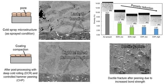
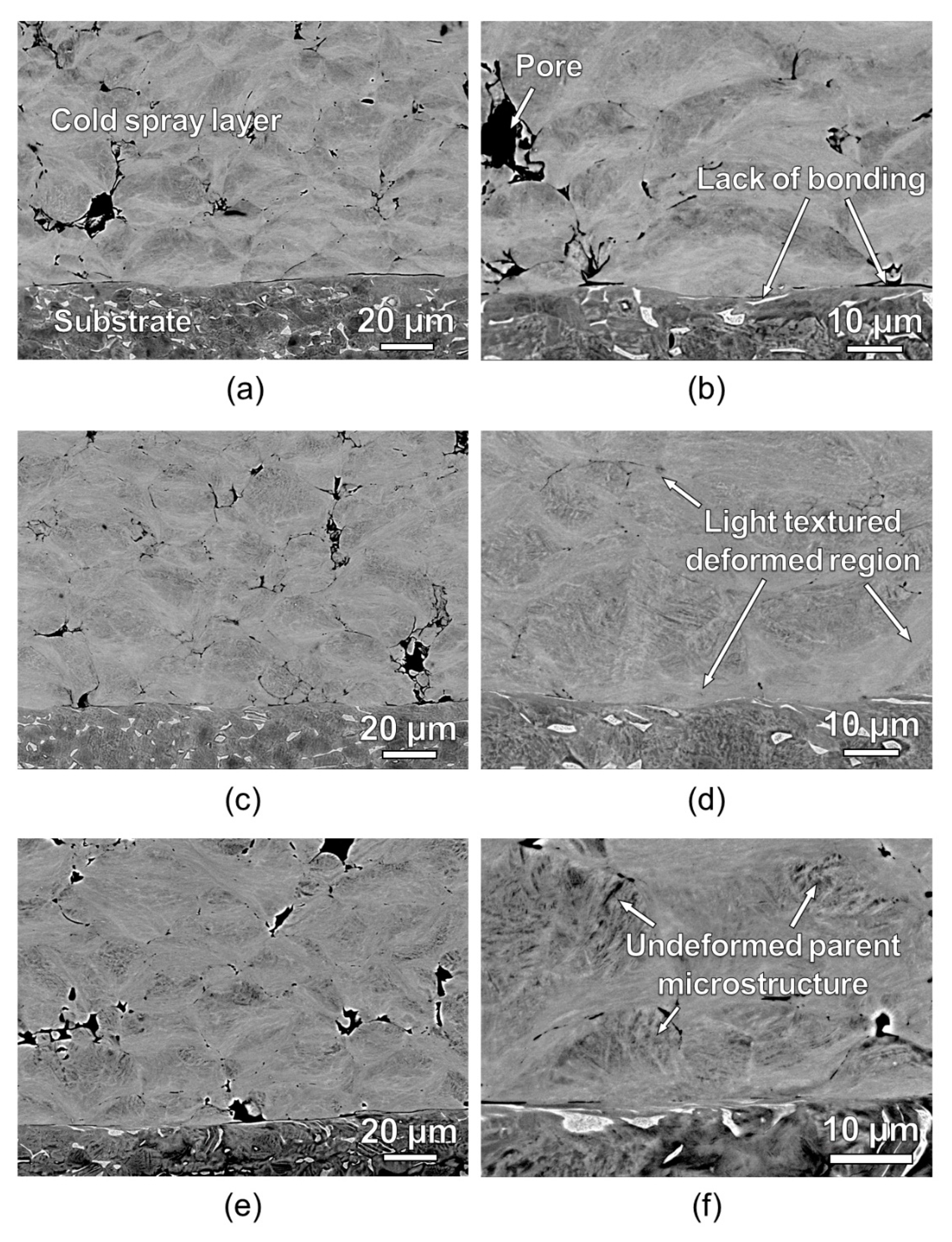
3.1. As-Sprayed Microstructure
3.2. Comparison of Mechanical Peening Processes
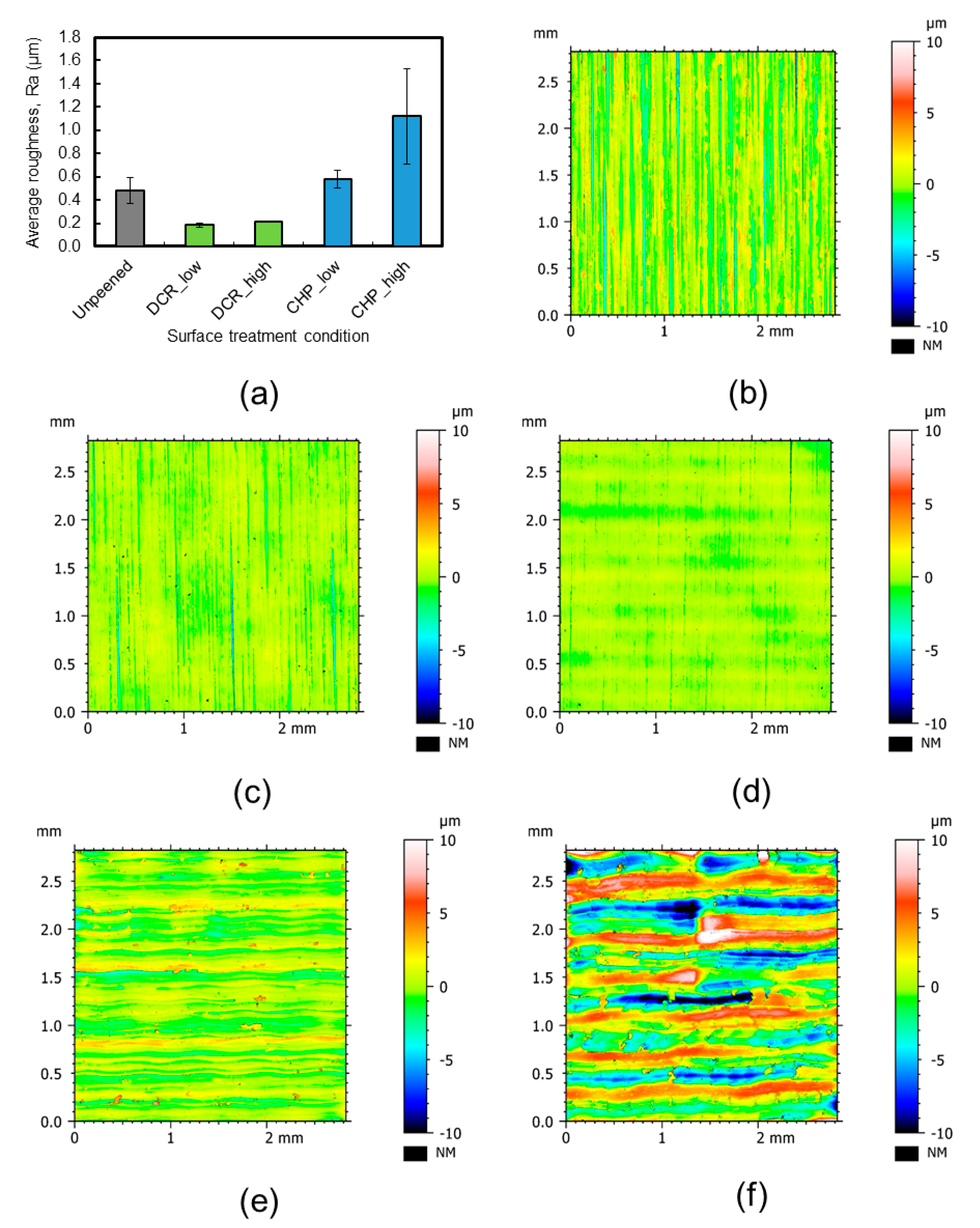
3.2.1. Surface Roughness
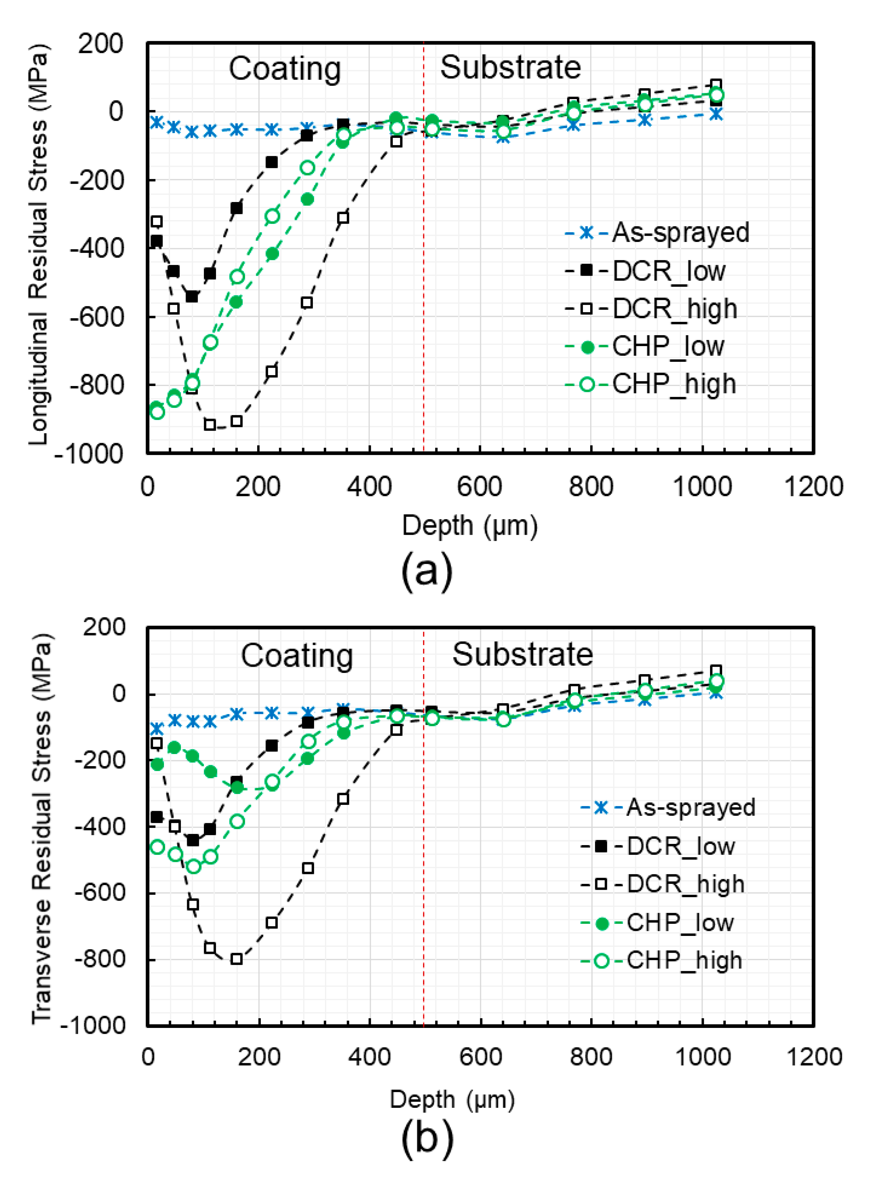
3.2.2. Residual Stresses
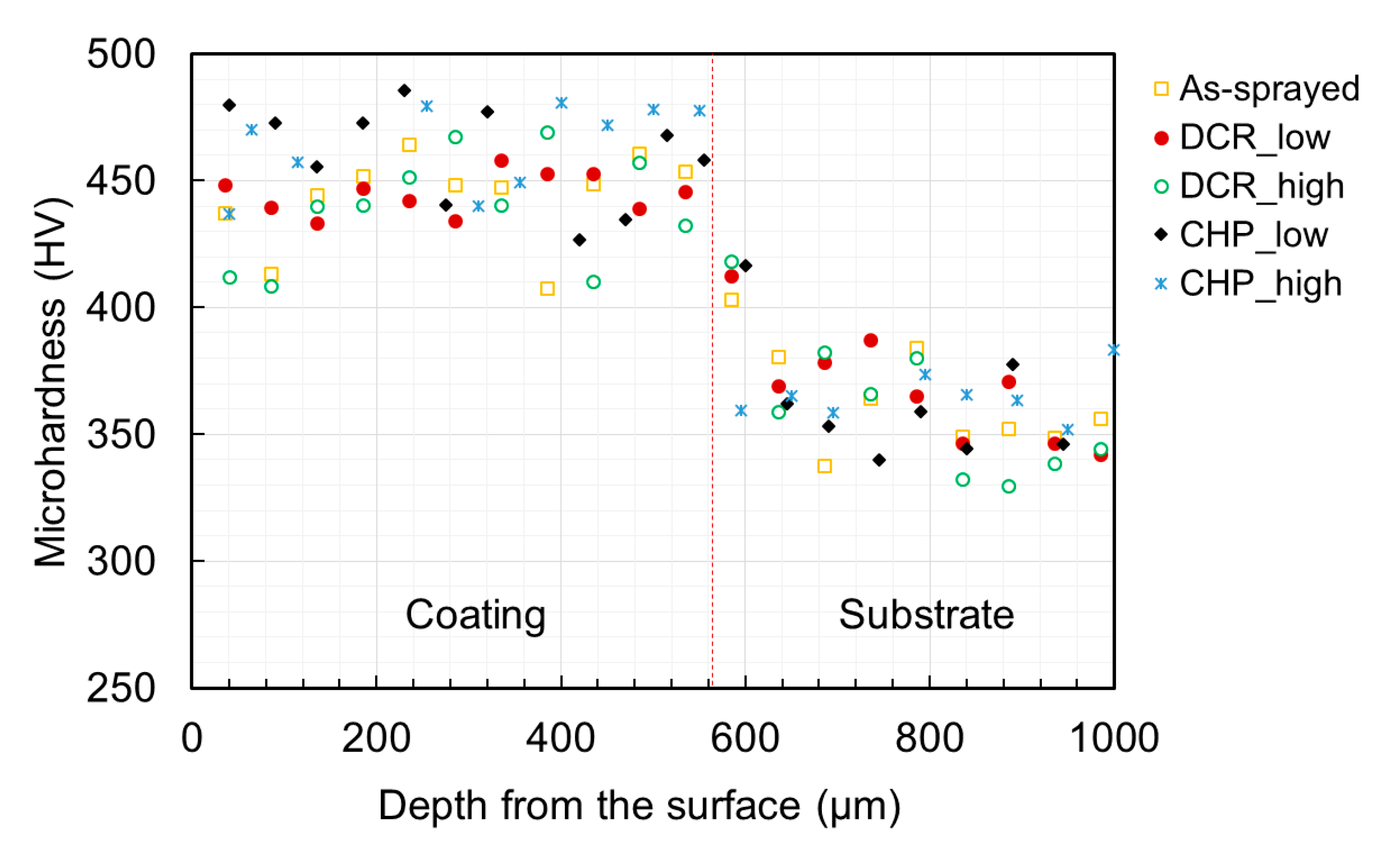
3.2.3. Hardness
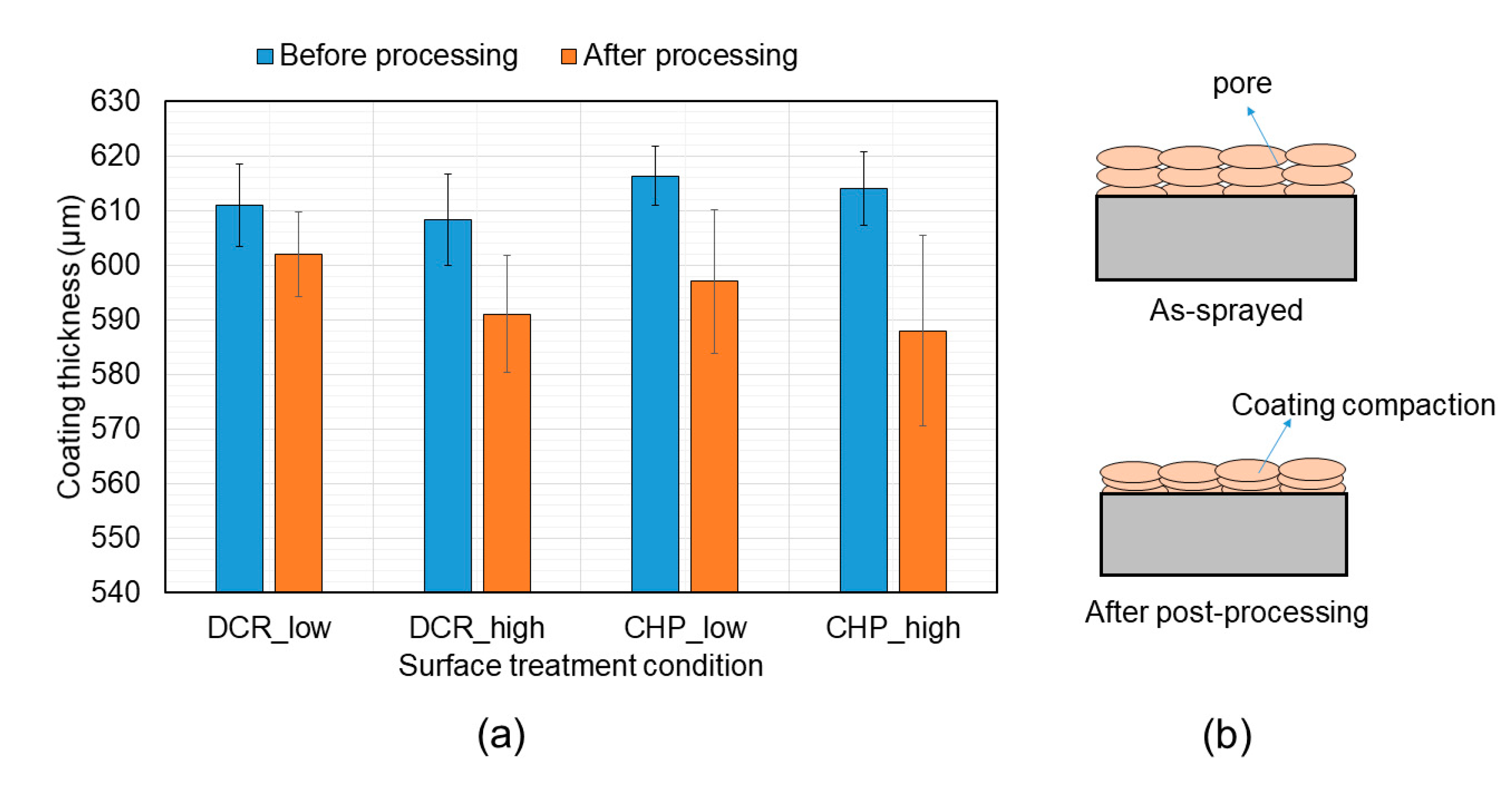
3.2.4. Porosity
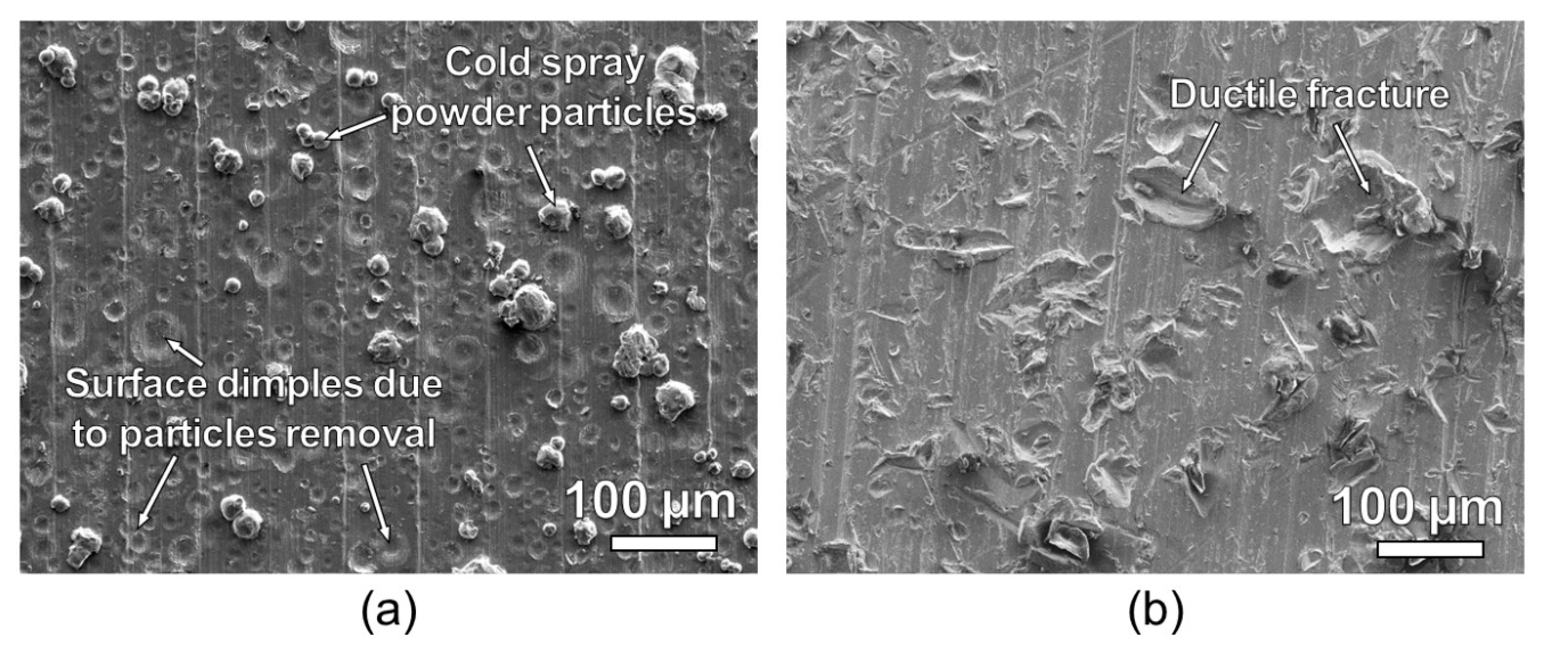
3.2.5. Bond Strength
4. Discussion
5. Conclusions
- Both DCR and CHP can reduce porosity and improve bond strength. Porosity reduced by as much as 71% and bond strength improved.
- DCR produced a smoother surface compared to the as-sprayed surface with an average roughness reducing from 0.5 to 0.2 μm. CHP resulted in an increase in surface roughness due to the formation of large dimples by the peening tool.
- The hardness of the cold spray coating was approximately 28% higher than that of the substrate. Mechanical peening did not bring a significant change in hardness.
- High compressive residual stresses were induced in the coating after DCR and CHP. Compressive stresses as high as 900 MPa was recorded. CHP yielded significantly different compressive stresses in different directions (longitudinal and transverse) indicating its anisotropic nature. In addition, no particular difference in residual stresses was observed at the coating–substrate interface.
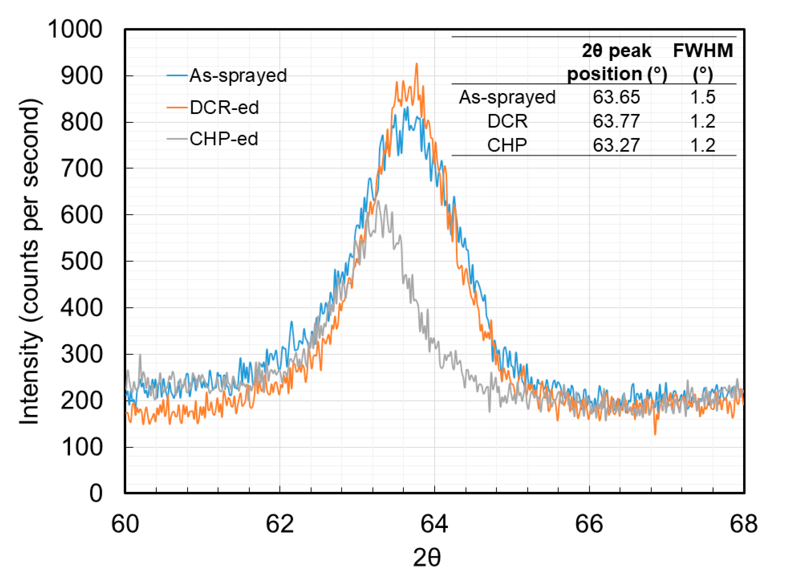
- CHP resulted in greater compaction and induction of lattice strains within the coating as compared to DCR.
- The increase in bond strength after post-processing is attributed to the compacting effect of the peening processes (reduced porosity) and to the greater degree of particle bonding with the substrate.
Author Contributions
Funding
Data Availability Statement
Acknowledgments
Conflicts of Interest
References
- Assadi, H.; Kreye, H.; Gärtner, F.; Klassen, T. Cold spraying–A materials perspective. Acta Mater. 2016, 116, 382–407. [Google Scholar] [CrossRef] [Green Version]
- Yin, S.; Cavaliere, P.; Aldwell, B.; Jenkins, R.; Liao, H.; Li, W.; Lupoi, R. Cold spray additive manufacturing and repair: Fundamentals and applications. Addit. Manuf. 2018, 21, 628–650. [Google Scholar] [CrossRef]
- Li, C.-J.; Li, W.-Y. Deposition characteristics of titanium coating in cold spraying. Surf. Coat. Technol. 2003, 167, 278–283. [Google Scholar] [CrossRef]
- Li, W.; Cao, C.; Yin, S. Solid-state cold spraying of Ti and its alloys: A literature review. Prog. Mater. Sci. 2020, 110, 100633. [Google Scholar] [CrossRef]
- Li, W.Y.; Zhang, C.; Guo, X.; Xu, J.; Li, C.J.; Liao, H.; Coddet, C.; Khor, K.A. Ti and Ti-6Al-4V coatings by cold spraying and microstructure modification by heat treatment. Adv. Eng. Mater. 2007. [Google Scholar] [CrossRef]
- Vo, P.; Irissou, E.; Legoux, J.G.; Yue, S. Mechanical and microstructural characterization of cold-sprayed Ti-6Al-4V after heat treatment. J. Therm. Spray Technol. 2013, 22, 954–964. [Google Scholar] [CrossRef]
- Tan, A.W.Y.; Sun, W.; Bhowmik, A.; Lek, J.Y.; Marinescu, I.; Li, F.; Khun, N.W.; Dong, Z.; Liu, E. Effect of coating thickness on microstructure, mechanical properties and fracture behaviour of cold sprayed Ti6Al4V coatings on Ti6Al4V substrates. Surf. Coat. Technol. 2018. [Google Scholar] [CrossRef]
- Goldbaum, D.; Shockley, J.M.; Chromik, R.R.; Rezaeian, A.; Yue, S.; Legoux, J.G.; Irissou, E. The effect of deposition conditions on adhesion strength of Ti and Ti6Al4V cold spray splats. J. Therm. Spray Technol. 2012, 21, 288–303. [Google Scholar] [CrossRef]
- Boruah, D.; Ahmad, B.; Lee, T.L.; Kabra, S.; Syed, A.K.; McNutt, P.; Doré, M.; Zhang, X. Evaluation of residual stresses induced by cold spraying of Ti-6Al-4V on Ti-6Al-4V substrates. Surf. Coat. Technol. 2019. [Google Scholar] [CrossRef]
- Sun, W.; Tan, A.W.Y.; Khun, N.W.; Marinescu, I.; Liu, E. Effect of substrate surface condition on fatigue behavior of cold sprayed Ti6Al4V coatings. Surf. Coat. Technol. 2017, 320, 452–457. [Google Scholar] [CrossRef]
- Adebiyi, D.I.; Popoola, A.P.; Botef, I. Experimental verification of statistically optimized parameters for low-pressure cold spray coating of titanium. Metals 2016, 6, 135. [Google Scholar] [CrossRef] [Green Version]
- Zahiri, S.H.; Antonio, C.I.; Jahedi, M. Elimination of porosity in directly fabricated titanium via cold gas dynamic spraying. J. Mater. Process. Technol. 2009, 209, 922–929. [Google Scholar] [CrossRef]
- Bhowmik, A.; Wei-Yee Tan, A.; Sun, W.; Wei, Z.; Marinescu, I.; Liu, E. On the heat-treatment induced evolution of residual stress and remarkable enhancement of adhesion strength of cold sprayed Ti–6Al–4V coatings. Results Mater. 2020. [Google Scholar] [CrossRef]
- Astarita, A.; Rubino, F.; Carlone, P.; Ruggiero, A.; Leone, C.; Genna, S.; Merola, M.; Squillace, A. On the improvement of AA2024 wear properties through the deposition of a cold-sprayed titanium coating. Metals 2016, 6, 185. [Google Scholar] [CrossRef] [Green Version]
- Nalla, R.K.; Altenberger, I.; Noster, U.; Liu, G.Y.; Scholtes, B.; Ritchie, R.O. On the influence of mechanical surface treatments-deep rolling and laser shock peening-on the fatigue behavior of Ti-6Al-4V at ambient and elevated temperatures. Mater. Sci. Eng. A 2003. [Google Scholar] [CrossRef]
- Moridi, A.; Hassani-Gangaraj, S.M.; Vezzú, S.; Trško, L.; Guagliano, M. Fatigue behavior of cold spray coatings: The effect of conventional and severe shot peening as pre-/post-treatment. Surf. Coat. Technol. 2015. [Google Scholar] [CrossRef]
- Luo, X.T.; Wei, Y.K.; Wang, Y.; Li, C.J. Microstructure and mechanical property of Ti and Ti6Al4V prepared by an in-situ shot peening assisted cold spraying. Mater. Des. 2015. [Google Scholar] [CrossRef]
- Tan, A.W.-Y.; Sun, W.; Phang, Y.P.; Dai, M.; Marinescu, I.; Dong, Z.; Liu, E. Effects of traverse scanning speed of spray nozzle on the microstructure and mechanical properties of cold-sprayed Ti6Al4V coatings. J. Therm. Spray Technol. 2017, 26, 1484–1497. [Google Scholar] [CrossRef]
- Grant, P.V.; Lord, J.D.; Whitehead, P. The Measurement of Residual Stresses by the Incremental Hole Drilling Technique. Meas. Good Pract. Guid. 2006, 53, 1–70. [Google Scholar]
- Marzbanrad, B.; Toyserkani, E.; Jahed, H. Customization of residual stress induced in cold spray printing. J. Mater. Process. Technol. 2020, 289, 116928. [Google Scholar] [CrossRef]
- Kopsov, I.E. The influence of hammer peening on fatigue in high-strength steel. Int. J. Fatigue 1991, 13, 479–482. [Google Scholar] [CrossRef]
- Zhuang, W.; Liu, Q.; Djugum, R.; Sharp, P.K.; Paradowska, A. Deep surface rolling for fatigue life enhancement of laser clad aircraft aluminium alloy. Appl. Surf. Sci. 2014, 320, 558–562. [Google Scholar] [CrossRef]
- Oevermann, T.; Wegener, T.; Niendorf, T. On the evolution of residual stresses, microstructure and cyclic performance of high-manganese austenitic TWIP-steel after deep rolling. Metals 2019, 9, 825. [Google Scholar] [CrossRef] [Green Version]
- Ghelichi, R.; Bagherifard, S.; Macdonald, D.; Fernandez-Pariente, I.; Jodoin, B.; Guagliano, M. Experimental and numerical study of residual stress evolution in cold spray coating. Appl. Surf. Sci. 2014. [Google Scholar] [CrossRef]
- Wong, C.C.; Hartawan, A.; Teo, W.K. Deep cold rolling of features on aero-engine components. In Proceedings of the Procedia CIRP, 2nd CIRP Conference on Surface Integrity (CSI), Nottingham, UK, 28–30 May 2014. [Google Scholar]
- Hussain, T. Cold Spraying of Titanium: A Review of Bonding Mechanisms, Microstructure and Properties. Key Eng. Mater. 2012. [Google Scholar] [CrossRef]
- Song, X.; Everaerts, J.; Zhai, W.; Zheng, H.; Tan, A.W.Y.; Sun, W.; Li, F.; Marinescu, I.; Liu, E.; Korsunsky, A.M. Residual stresses in single particle splat of metal cold spray process—Numerical simulation and direct measurement. Mater. Lett. 2018. [Google Scholar] [CrossRef]
- Lek, J.Y.; Bhowmik, A.; Tan, A.W.Y.; Sun, W.; Song, X.; Zhai, W.; Buenconsejo, P.J.; Li, F.; Liu, E.; Lam, Y.M.; et al. Understanding the microstructural evolution of cold sprayed Ti-6Al-4V coatings on Ti-6Al-4V substrates. Appl. Surf. Sci. 2018. [Google Scholar] [CrossRef]
- Hönnige, J.R.; Davis, A.E.; Ho, A.; Kennedy, J.R.; Neto, L.; Prangnell, P.; Williams, S. The Effectiveness of Grain Refinement by Machine Hammer Peening in High Deposition Rate Wire-Arc AM Ti-6Al-4V. Metall. Mater. Trans. A Phys. Metall. Mater. Sci. 2020. [Google Scholar] [CrossRef]
- Kumar, D.; Idapalapati, S.; Wang, W.; Narasimalu, S. Effect of surface mechanical treatments on the microstructure-property-performance of engineering alloys. Materials 2019, 12, 2503. [Google Scholar] [CrossRef] [Green Version]


| Machine Used | Plasma Giken |
|---|---|
| Working gas | Nitrogen |
| Gas Pressure | 5 MPa |
| Gas Temperature | 1000 °C |
| Robot velocity (traverse speed) | 500 mm/s |
| Spray angle | 90° |
| Powder feed rate | 12 g/min |
| Step size | 0.5 mm |
| Original powder size | 45 μm (3–90 μm) |
| Sample Code | Pressure (Bar) | Coverage | Ball Size ø(mm) | Feed Rate (mm/min) | Average Track Width (mm) | Number of Repeats |
|---|---|---|---|---|---|---|
| DCR_low | 100 | 200% | 6 | 1000 | 0.16 | 3 |
| DCR_high | 300 | 200% | 6 | 1000 | 0.25 | 3 |
| Sample Code | Ball Size (mm) | Spindle Speed (RPM) | Frequency (Hz) | Feed Rate (mm/min) | Step Size (mm) | Stand off Z+ (mm) | Number of Repeats |
|---|---|---|---|---|---|---|---|
| CHP_low | 8 | 800 | 80 | 500 | 0.1 | 1 | 3 |
| CHP_high | 50 | 1200 | 120 | 1500 | 0.2 | 1 | 3 |
| Condition | Failure Mode | Average Bond Strength (MPa) | ||
|---|---|---|---|---|
| 1 | 2 | 3 | ||
| As-sprayed | I | I | I | 76 ± 4 |
| DCR_low | E | E | E | >84 |
| DCR_high | E | E | E | >80 |
| CHP_low | E | I | E | >53 |
| CHP_high | E | E | E | >81 |
Publisher’s Note: MDPI stays neutral with regard to jurisdictional claims in published maps and institutional affiliations. |
© 2021 by the authors. Licensee MDPI, Basel, Switzerland. This article is an open access article distributed under the terms and conditions of the Creative Commons Attribution (CC BY) license (https://creativecommons.org/licenses/by/4.0/).
Share and Cite
Maharjan, N.; Bhowmik, A.; Kum, C.; Hu, J.; Yang, Y.; Zhou, W. Post-Processing of Cold Sprayed Ti-6Al-4V Coatings by Mechanical Peening. Metals 2021, 11, 1038. https://doi.org/10.3390/met11071038
Maharjan N, Bhowmik A, Kum C, Hu J, Yang Y, Zhou W. Post-Processing of Cold Sprayed Ti-6Al-4V Coatings by Mechanical Peening. Metals. 2021; 11(7):1038. https://doi.org/10.3390/met11071038
Chicago/Turabian StyleMaharjan, Niroj, Ayan Bhowmik, Chunwai Kum, Jiakun Hu, Yongjing Yang, and Wei Zhou. 2021. "Post-Processing of Cold Sprayed Ti-6Al-4V Coatings by Mechanical Peening" Metals 11, no. 7: 1038. https://doi.org/10.3390/met11071038