Article

Effect of PWHT on the Microstructure and Mechanical Properties of Friction Stir Welded DP780 Steel

1
Department of Mechanical Engineering, Incheon National University, Incheon 22012, Korea
2
Research Institute for Engineering and Technology, Incheon National University, Incheon 22012, Korea
*
Author to whom correspondence should be addressed.
These authors contributed equally to this work.
Metals 2021, 11(7), 1097; https://doi.org/10.3390/met11071097
Submission received: 31 May 2021 / Revised: 1 July 2021 / Accepted: 8 July 2021 / Published: 10 July 2021

Abstract

:
In the present study, the effect of post-weld heat treatment (PWHT) on the microstructure and mechanical properties of friction stir welded (FSW) DP780 steel sheets was investigated. FSW was carried out at a constant tool rotation speed of 400 rpm and different welding speeds (200 mm/min and 400 min/min). A defect free weld was witnessed for both of the welding conditions. The mutual effect of severe plastic deformation and frictional heat generation by pin rotation during the FSW process resulted in grain refinement due to dynamic recrystallization in the stir zone (SZ) and thermo-mechanically affected zone (TMAZ). Lower tensile elongation and higher yield and ultimate tensile strengths were recorded for welded-samples as compared to the base material (BM) DP780 steel. The joints were subsequently annealed at various temperatures at 450–650 °C for 1 h. At higher annealing temperature, the work hardening rate of joints gradually decreased and subsequently failed in the softened heat-affected zone (HAZ) during the uniaxial tensile test. Reduction in yield strength and tensile strength was found in all PWHT conditions, though improvement in elongation was achieved by annealing at 550 °C. The digital image correlation analysis showed that an inhomogeneous strain distribution occurred in the FSWed samples, and the strain was particularly highly localized in the advancing side of interface zone. The nanoindentation measurements covering the FSWed joint were consistent with an increase of the annealing temperature. The various grains size in the BM, TMAZ, and SZ is the main factor monitoring the hardness distribution in these zones and the observed discrepancies in mechanical properties.

1. Introduction

Ferrite-martensite dual-phase (DP) steels are the most prevalent member of advanced high-strength steels (AHSSs), which contains a continuous matrix of ferrite with the dispersed islands of martensite [1]. The presence of a ductile ferrite matrix with the substantially hard martensite phase results in excellent strength-ductility synergy [2]. Thus, DP steels have been considered as a potential candidate for weight reduction and crash resistance applications in the automotive industry (e.g., body panels, bumper), owing to their excellent mechanical strength, continuous yielding behavior, high work hardening rate, high strain energy absorption, and exceptional formability [3,4,5].
Despite having adequate properties, the widespread applications of DP steels are hampered due to the inferior mechanical properties of weld joints. As DP steels are mostly fusion welded, the heat-affected zone (HAZ) softening, porosity, formation of solidification cracks, and presence of high residual stresses are the key bottleneck issues limiting its diverse utilization [6]. The significant modification of microstructure (e.g, intermetallic compounds, brittle martensite, etc.) in the fusion zone (FZ) and HAZ due to heat input usually result in the poor mechanical performance of the welded joints as compared to the base metal (BM). The strain accumulation and localization occur in the softened HAZ zone during deformation, resulting in premature failure [7]. Hence, precise control on the metallurgical and thermal factors using the optimized welding parameters that drive heat input can accomplish the proper welding of DP steels, which is nevertheless extremely difficult. Accordingly, it has motivated researchers to develop innovative solid-state joining/welding techniques with low heat input requirements to mitigate the challenges mentioned above. Among all, friction stir welding (FSW) has been considered to be the most promising solution to this long withstanding issues [8].
FSW offers multiple advantages over conventional welding techniques such as excellent energy efficiency, no use of filler materials, and shielding gas. Owing to its solid-state nature, FSW allows welding with less heat input, giving rise to a quite low processing temperature that remains below the melting temperature of the workpiece material which, in turn, reduces the HAZ softening, decreases residual stresses, and minimizes solidification defects [9,10,11]. In addition, FSW processing parameters such as tilting angle, rotating tool speed, and welding transversal speed can be adjusted to improve the tensile strength of the assembly. Regardless of fascinating advantages, the implementation of FSW has been limited to low melting temperature materials such as aluminum and magnesium. In contrast, only limited studies have reported on FSW of DP steel [12,13,14,15,16]. For instance, Kim et al. performed FSW for cold-rolled DP590 steel sheet with a 600–1000 rpm tool rotation speed and travelling speed of 120–420 mm/min to find the optimum welding parameters [17]. The relative ratio of rotation speed to travelling speed, N/V (RPM/(mm/min)), which represents heat input per unit length revealed that the high-quality weld joints were received for N/V values between 2.2–4.2 RPM/(mm/min). However, for higher welding speed, groove-like defects were observed in the advancing side due to insufficient heat input. Matsushita et al. studied the influence of several welding conditions on the microstructural evolution and mechanical properties of various AHSS grades [18]. The large volume fraction of martensite and high hardness in the stirred zone (SZ) was observed at a higher tool rotation speed, attributed to the increase in peak temperature of its thermal cycle. In addition, tensile strength for 980 MPa was recorded to be similar for the weld joint and BM, but for 1180 MPa the tensile strength was reduced due to the HAZ softening. In another study, the defect-free welds were reported for DP700 steel sheet at the rotation speed of 800 rpm and welding speed of 100 and 150 mm/min. In contrast, an inferior quality weld was observed at welding speed of 200 mm/min due to insufficient heat input [19]. It was concluded that the increase in welding speed resulted in reducing the peak temperature (885 °C and 813 °C for 100 and 150 mm/min, respectively), which resulted in the evolution of finer and harder grains in the SZ. The microhardness of the SZ for welding speed of 100 and 150 mm/min was recorded to be higher than the BM viz: 370 HV and 395 HV and 275 HV, respectively, which was attributed to the grain refinement and higher cooling rate in the SZ.
Hence, based on the above discussion, it can be concluded that the microstructural evolution primarily determines the overall mechanical performance and fracture behavior of the FSWed joints during the FSW process. As it is well established that the FSW parameters (i.e., tool rotation speed, welding speed, tilt angle) have a significant effect on the microstructure and phase transformation at various regions of the weld, there is thus an immense need to understand and correlate the microstructural features with the FSW parameters. Moreover, little attention has been paid to the benefits of the post-weld heat treatment (PWHT) of FSWed joints of DP steels, which already proved its effectiveness for other materials [15].
In the present study, accordingly, the effect of constant tool speed of 400 rpm and different welding speeds (200 mm/min and 400 mm/min) on the microstructural evolution and overall mechanical properties of FSWed DP780 steel sheets was systemically studied. The PWHT was carried out at 450 °C, 550 °C, and 650 °C for 1 h, followed by air cooling for all FSWed samples. Uniaxial tensile tests were performed in the presence of a charge-coupled device camera for the digital image correlation (DIC) analysis to explain the strain evolution during deformation. Finally, indentation-based hardness mapping was carried out on as-welded samples to emphasize the microstructure-property relationship.

2. Materials and Methods

A commercial-grade rolled DP780 steel sheet with a thickness of 1.4 mm was used in the present study. The chemical composition of DP780 steel is illustrated in Table 1. The FSW experiment was conducted on the sheets with the dimensions of 80 mm × 150 mm along the transverse direction using the FSW machine (F1300, Hwacheon Machinery, Gwangju, Korea). Welding was performed at a constant tool rotation speed of 400 rpm with different welding speeds (200 and 400 mm/min) at a tilt angle of 3° (see Table 2). The tool force was kept constant at 2 kN. The detailed description of the welding process and sample configuration can be seen from the schematics presented in Figure 1a. A truncated cone-shaped tool made of WC-Co material with a shoulder diameter of 10 mm, pin length and diameter of 1.4 mm and 4 mm, respectively, was used as a welding tool. For the sake of simplicity, the samples will be referred to as FSW400-200 and FSW400-400 for the different abovementioned welding conditions. Furthermore, the PWHT was performed on both samples at 450 °C, 550 °C, and 650 °C, followed by air cooling to room temperature. The PWHT samples are called PWHT 450-42, PWHT 550-42, PWHT 650-42 for samples welded at the welding speed of 200 mm/min and PWHT 450-44, PWHT 550-44, PWHT 650-44 for FSWed samples at the welding speed of 400 mm/min.
For microstructural characterization, samples comprising BM, thermo-mechanically affected zone (TMAZ), HAZ, and SZ were cut from the welded plate, followed by the metallographic preparation. The samples were ground using SiC papers from 200 until 2000 grit size, were subsequently polished by diamond suspension (0.04 μm), and 4% Nital was used as an etchant to reveal the microstructure. The microstructure was then observed using Zeiss AXIO scope (Axioscope A1, Carl Zeiss, Oberkochen, Germany) and JEOL JSM-7800F field emission scanning electron microscopy (FE-SEM, JSM-7800F, JEOL Ltd., Tokyo, Japan). After the welding process, the tensile samples were cut from the sheet keeping the weld in the center. The room temperature uniaxial tension test was performed using standard dog-bone shaped samples at the strain rate of 10−3 s−1 at a constant crosshead speed of 1.5 mm/min. A charge-coupled device camera was used throughout the test to monitor the strain evolution during deformation using the DIC analysis. Finally, the hardness distribution was probed using a nanoindentation tester (NHT3; Anton Paar) with a diamond Berkovich tip. The maximum depth of 1.5 μm and the indent spacing of 250 μm was selected. Indentation local hardness was calculated using the Oliver and Pharr method (Equation (1)) [20]:
H = Pmax/A,
where Pmax is the maximum indentation load and A is the projected area by a penetration of the indenter. Elastic modulus can be obtained by measuring the effective elastic modulus Er (Equation (2)) [20]:
1/Er = 1/[(1 − v2)/E + (1 − vi2)/Ei)],
where E and Ei, are specimen and indenter moduli, respectively, and v and vi are Poisson’s ratio of specimen and indenter, respectively.
The measured hardness maps were interpolated and plotted using MATLAB built-in functions. A Vickers hardness test was also performed using a SHIMADZU HMV-G micro Vickers hardness testing machine with a load of 4.903 N (HV0.5) and a duration for 10 s.

3. Results and Discussion

3.1. Microstructure and Mechanical Properties of the FSWed DP780

Figure 1b shows the SEM micrographs of the DP780 steel. It can be seen from the figure that the microstructure primarily consists of the white martensite phase disseminated in the dark ferrite matrix. Figure 1c represents the top view of 400-200 FSWed joint and transverse view of the 400-200 and 400-400 FSWed joints. No significant difference in top view of both the welded joints was visible with naked eye so only FSWed 400-200 is shown here. As it is evident that both the welding conditions resulted in the successful defect free welds, which can be described as a rough surface of bead due to the extensive burr and sound bead without any defect. It is pertinent to mention that Mahdi et al. [19] investigated the optimum FSW parameters of DP700 steel sheets and reported the formation of groove-like defects at the welding speed of 200 mm/min. Interestingly, no such defects were observed in the present study even at the higher welding speed of 400 mm/min, and a decent quality weld was received.
The microstructure evolution in the BM, TMAZ, and SZ for FSW400-200 and FSW 400-400 can be seen in Figure 2. No significant changes were noticed in the BM for both the welded samples. Figure 2b,e illustrate the microstructural characteristics of TMAZ for FSW400-200 and FSW400-400, respectively. The grain refinement was noticed, and the overall grain size was smaller in the TMAZ zone for the FSW400-400 than FSW400-200. It is well established that the FSW can be considered as a thermomechanical process, owing to its combined effects of the severe plastic deformation and subsequently frictional heat generation by pin rotation. The localization of deformation and temperature can develop the gradients of strain and temperature along the processed region. Hence, investigating the microstructural evolution and recovery mechanisms during FSW is more challenging. Moreover, higher welding speeds can accelerate the dynamic recrystallization (DRX) mechanism during FSW process, resultingly in finer grains in the TMAZ of FSW 400-400 sample as compared to the FSW400-200 sample. The microstructure of the SZ of FSW400-200 and FSW400-400 is presented in Figure 2c,f, respectively. It is evident from the figure that the resulted microstructure in the SZ of FSW400-200 and FSW400-400 is a more complex microstructure than the BM, where it mainly consists of the martensite phase due to austenitization treatment after the FSW process. Secondly, the grain refinement mechanisms in the SZ of FSW400-200 and FSW400-400 can be attributed to the evolution of DRX behavior during the FSW process.
The microhardness profiles across the welded joints are presented in Figure 3a. The average hardness value of DP780 steel was about 295 ± 44.9 HV and 273 ± 36.2 HV for FSW400-400 and FSW400-200, respectively. For both joints, an area in which the hardness locally dropped to values below the BM hardness was detected in the HAZ. The formation of this area, which is called the softened zone, is attributed to the tempering of the pre-existing martensite. It was shown that the decomposed martensite was the major contributor to the softening in the HAZ [19,21]. To provide additional insight into the structural effect on deformation, nanoindentation tests were performed on the joints. The local hardness and modulus maps are displayed in Figure 3b. The region with higher local hardness values in FSW400-400 and FSW400-200 samples is well consistent with the indicated softening area. Moreover, the point clouds are gradually lowered from the average hardness of 3.6 ± 0.4 GPa and elastic modulus of 296 ± 20 GPa to that of 3.5 ± 0.4 GPa and 290 ± 21 GPa which corresponds to that of FSW 400-400 and 400-200 samples, respectively.
The representative engineering stress-strain curves concerning different welding conditions are given in Figure 4. Their strain evolution was corrected by synchronizing with DIC data. The resultant tensile properties are summarized and listed in Table 3.
It is shown that DP780 and FSWed samples yield without an obvious yielding platform, which is usually associated with the existing high mobile dislocation density in the microstructure. σ0.2 is stress measures taken at the point of detecting 0.2% plastic strain. DP780 undergoes continuous yielding behavior and low yield strength (σ0.2) to ultimate tensile strength (σUTS) ratio, which is a typical characteristic of DP steels [22]. The samples welded by FSW also exhibited continuous yielding behavior. For FSWed samples, the yield strengths were increased to 760 and 697 MPa for the FSW400-400 and FSW400-200 samples, respectively. These values are increased to those of the base material since the failure took place in the weld region of SZ due to the strength matching nature of the joint as seen from the strain maps of the sample before failure (see Figure 5). Owing to the higher tensile residual stress of SZ compared to surrounded regions, strain accumulates in the SZ, which induces a transverse deformation in the ND direction.
On the other hand, the FSW400-400 showed a higher εT (7.8%) with a wide tensile hardening region as compared to FSW400-200 (4.3%), but in both cases, the elongation was lower than the DP780 (23.4%). This is because the FSWed region does not contribute to the total elongation during the tensile test, leading to a reduction in the total elongation. The increase in the tensile elongation for FSW400-400 as compared to FSW400-200 can be explained based on high welding speed. It is well known that the tool speed and welding speed have a remarkable effect on the microstructure and mechanical properties of the welds. For instance, at constant tool speed, high feedrates produce softer welds with a large fraction of primary ferrite than the harder welds with high martensite fraction at lower feedrates [9]. Accordingly, the evolution of softer grains containing primary ferrite and grain refinement mechanism can be attributed to the higher elongation of FSW400-400.

3.2. Local Tensile Properties of the Joints after PWHT

The transverse cross-section microstructures of the as-welded FSW joint of DP 780 steel without internal defects are presented in Figure 6. It is revealed that the weld joint can be divided into three typical zones—namely, BM, TMAZ/HAZ, and SZ. Clear boundaries between the weld and BM zones were observed in Figure 6a. SZ grains are significantly refined, which can be attributed to the dynamic recrystallization. The post-weld heat treatment changed the macrostructure of the joints significantly, as seen in Figure 6b. It was shown that in the stir zone and the upper part of the TMAZ, the grainy microstructure suffered abnormal grain growth (AGG). This phenomenon occurred in each post-weld heat treatment sample, despite the welding parameters used.
The results of the tensile testing of joints in the as-welded state are compared with different heat treatment temperatures in Figure 7. Table 4 shows the main tensile properties of the joints. The samples showed an increase in the yield strength and the appearance of the yield plateaus after a PWHT as compared with the as-welded condition. Increasing temperature up to 650 °C, the tensile strength decreases continuously due to the dissolution of carbides and evolution on the recrystallization of few phases. It is noted that the PWHT450 sample results in a relatively higher yield strength of ~580 MPa as compared to the PWHT550 and PWHT650 samples; this trend can be assigned to the presence of hard structures (i.e., martensite) and undissolved precipitates (i.e., carbide phases). PWHT450 and 550 samples were predominantly fractured at the advancing side (AS) interface during the tensile test. As shown, the FSWed DP780 breaks in SZ, whereas the fracture is shifted to the TMAZ/HAZ in PWHT samples. However, this tendency did not persist for PWHT 550 400-400, where their fractures took place far away from the joints. Most of the samples showed a similar tendency in deformation behavior, except for an earlier failure in the PWHT650 sample. In the case of the PHWT 650 sample, its fracture took place at SZ. By increasing temperature up to 650 °C, the yield strength decreases continuously due to the dissolution of carbides with the reduction on the martensite phase fraction. These results confirmed that the uniform elongation of PWHT joints was higher than that for the as-welded samples despite softening of HAZ, which can be attributed to the narrower HAZ zone [23].
The deformation behavior of PWHT samples during tensile testing was investigated using DIC. Figure 8 shows the occurrence of plastic deformation and extension of the plastic region of these samples before failure, where a representative cross-section is expected to be observed. The contour maps of the strain distribution clearly revealed that an inhomogeneous plastic deformation occurred during the tensile tests of the welded samples. Therefore, it will be interesting to divide the cross-sectional area into several subareas at various levels of global elongation. Deformation on both sides of the SZ remains roughly symmetrical until a global elongation of 4%, as seen in Figure 8. The result indicates that the PWHT450 joint is under a uniform deformation stage in the early deformation stage. However, local necking is observed before failure. It is shown that the extensional strains were highly localized in the interface of the SZ and BM zones at AS. The joint failure occurred in the AS-TMAZ region, which has the lowest hardness value, as seen in Figure 9. It can be seen that after a small amount of plastic deformation, the elongation of the AS-HAZ quickly increased until the localization of strain occurred in one of them. In Figure 8b, it can be seen that the total elongation was significantly recovered from 6.8% in PWHT 450-44 to 15.4% in PWHT 550-44, owing to most of the tensile strains being concentrated especially on both the AS and RS interfaces (Figure 8b). However, most of the strain was tolerated by the SZ with the lowest elongation in the PWHT650 (Figure 8c). Interestingly, PWHT 650-42 showed higher elongation than the PWHT 650-44. Strain distribution in the tensile specimen was homogeneous in both PWHT 650-42 and PWHT 650-44 specimens. After 3% macroscopic tensile-strain, strain localization started in stir zone. The strain-localization in the PWHT 650-44 was relatively suppressed while the PWHT 650-42 showed early strain-localization. The maximum strain within the strain-localized region just before fracture was significantly larger in PWHT 650-42 specimen than that in the PWHT 650-44 specimen. The strain distribution in the PWTH650 sample is attributed to the microstructural heterogeneity. This is believed to be related to the grain growth in TMAZ/HAZ, as shown in Figure 6b, indicating that the carbon atoms diffuse to dislocation sites in TMAZ/HAZ, and pinning the mobile geometrically necessary dislocations (GNDs) could also contribute to the decrement of work hardening rate [24].

3.3. Local Hardness and Nanoindentation

According to the description above, local changes in microstructure and the local hardness of the FSWed DP780 during PWHT. The results of local hardness analysis of the samples subjected to the post-weld heat treatment are presented in Figure 9. The results show the fluctuations in local hardness in the TMAZ/HAZ, which suffers the AGG. Grain growth in the thermo-mechanically affected zone seems to greatly influence the distribution of the local hardness in the PWHT 650 samples. The obvious increment of hardness values in the SZ can be attributed to the high degree of grain refinement.
It was found that local hardness values continuously increase upon getting close to SZ due to the increased lath martensite phase amount. Nanoindentation tests were performed on the joints to compare the local hardness of the joints with different annealing temperatures. When the local hardness of the annealed samples was plotted in correspondence to their weld region, it was seen that hardness decreased with temperature in all cases. The increment in the hardness of RS is slightly different from that of AS. It could be responsible for AS dominant fracture and might contribute to the difference in heat input between AS and RS. Note that for PWHT 650, the lowest hardness values were observed even outside the SZ, and the tendency of higher values in RS-HAZ and TMAZ is reversed. This result indicates that the coarse grains formed during the recrystallization do not compensate for the softening due to the carbon diffusion in SZ. It is noteworthy that the width of the TMAZ decreases with increasing of the welding speed. The hardness in the BM also gradually decreased concerning annealing temperature, and the SZ became significantly softened as annealing temperature increased.

4. Conclusions

FSW was performed on the DP780 steel sheets at the fixed tool rotation speed and different welding speed in the current study. The PWHT was performed at 450 °C, 550 °C, and 650 °C for 1 h, followed by air cooling. The microstructural characteristics and mechanical properties of as-welded and PWHTed samples were critically investigated in the context of the microstructure-process-property relationship. The following findings can be drawn:
(1)
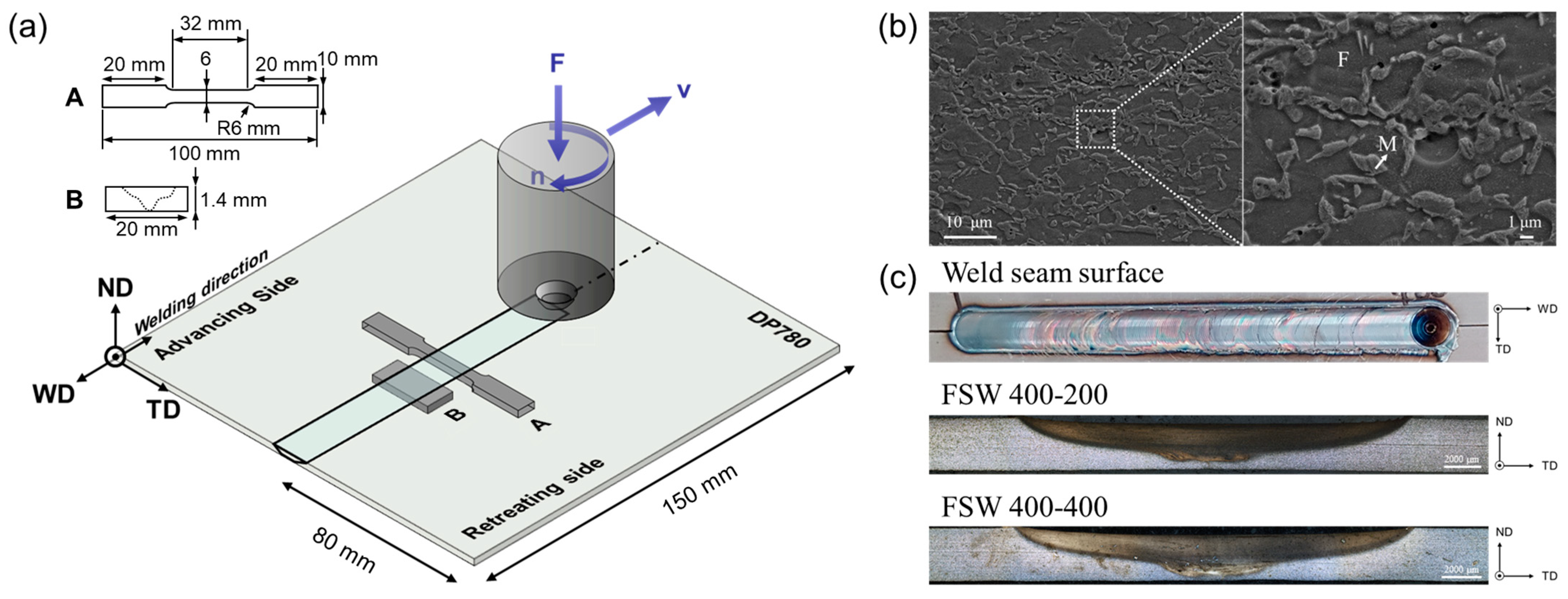
The defect-free welds with sound bead and rough surface were achieved at the fixed tool rotation speed (400 rpm) and different welding speed (200 and 400 mm/min).
(2)
The FSW process led to a refined microstructure consisting of ferrite and lath martensite in the SZ due to dynamic recrystallization; additionally, the formation of lath martensite induced a significant hardness rise in the stir zone. The tempered martensite caused the presence of a soft zone in the heat-affected zone.
(3)
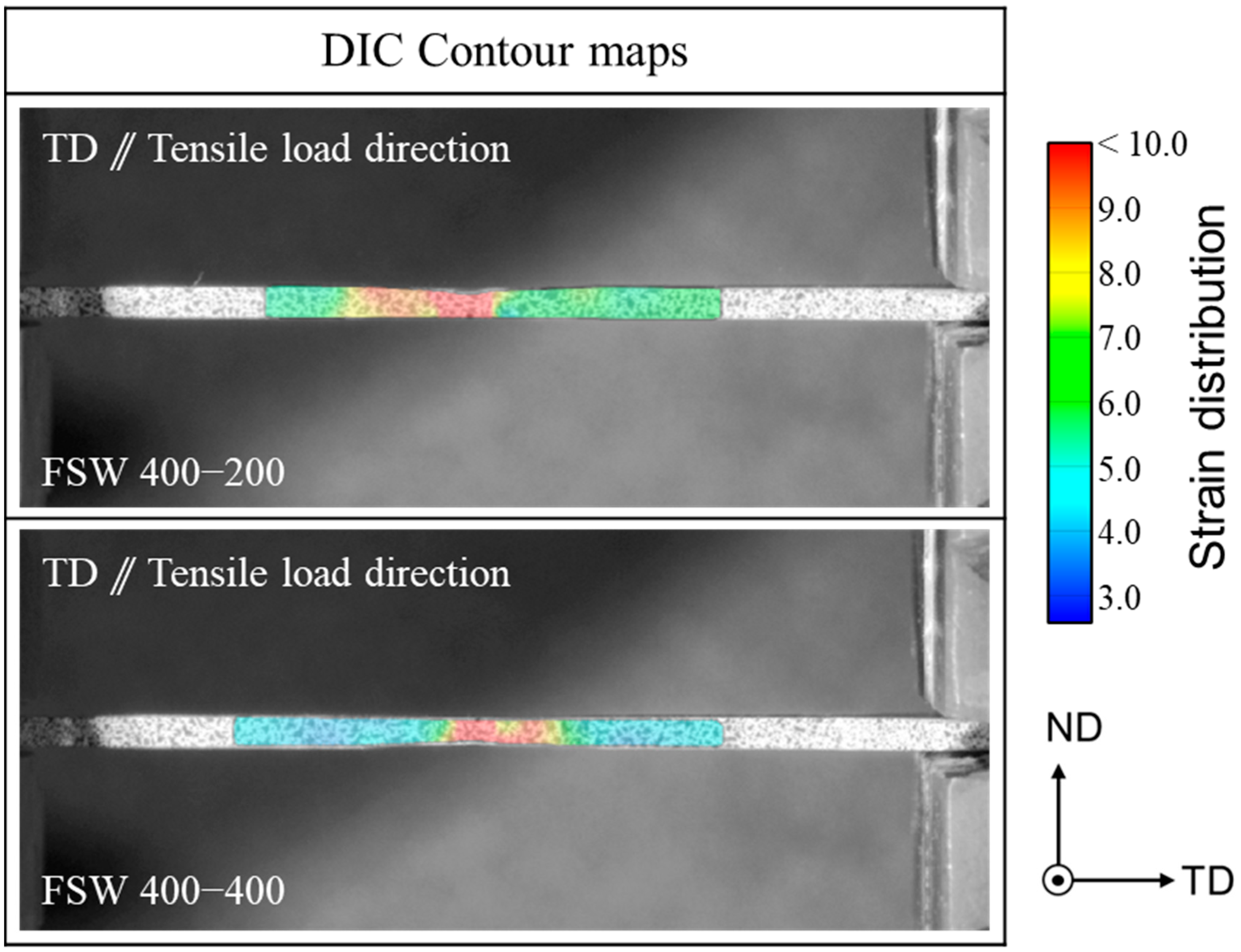
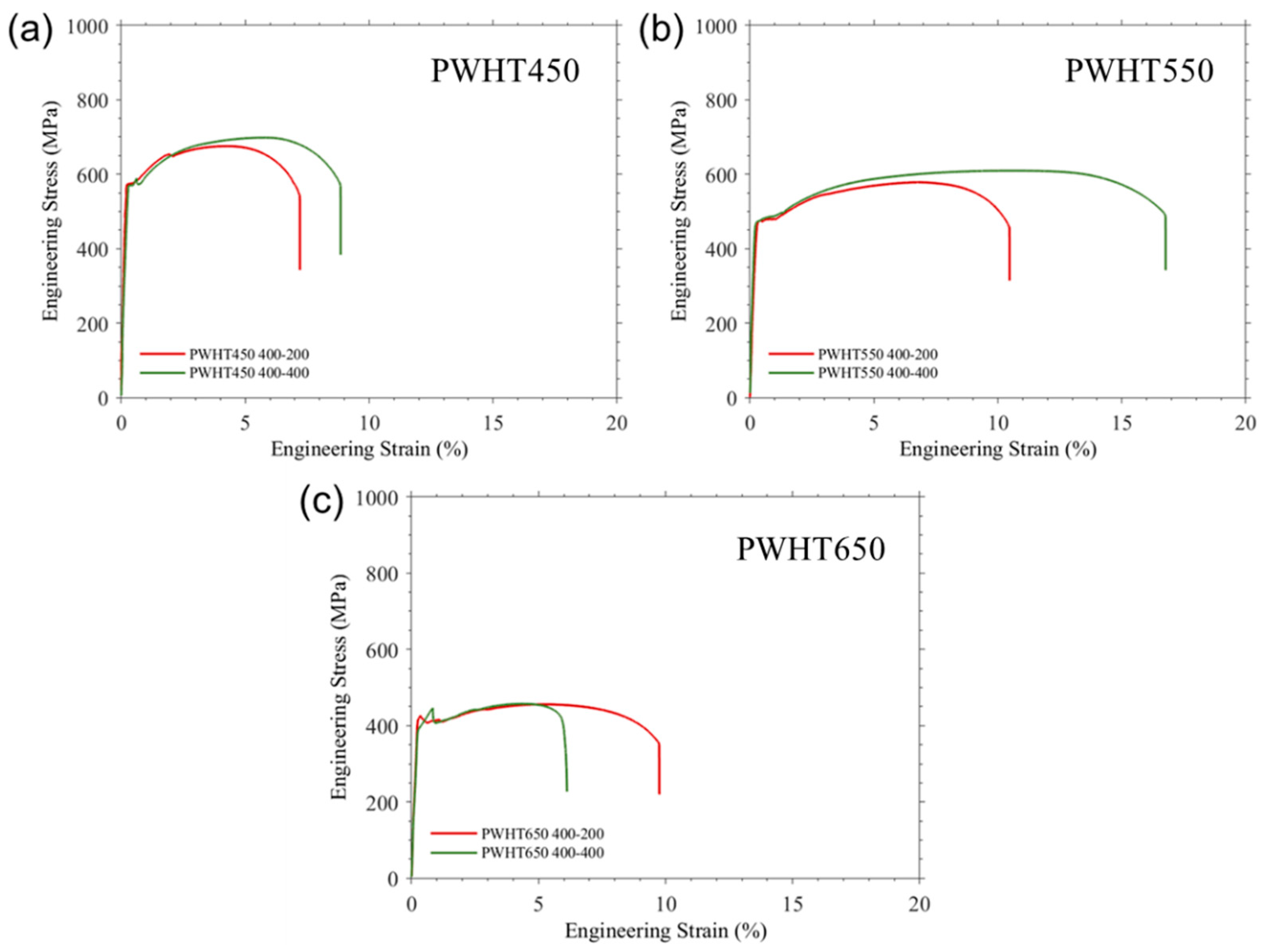
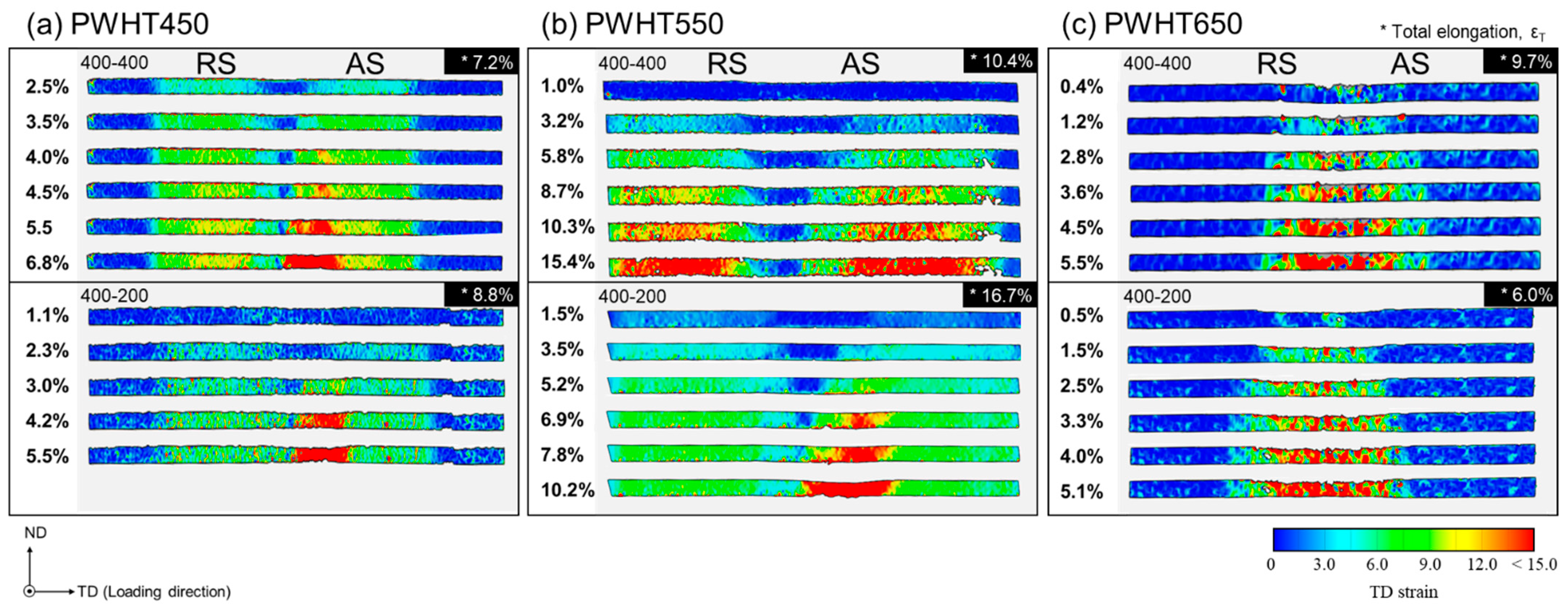
In the PWHT DP780 FSW joint, yield strength and tensile strength values are simultaneously improved due to the pre-existing hard phase such as martensite, but the ductility decreased in PWHT450 and PWHT650. Only the PWHT550-44 sample displayed the highest tensile strength and elongation. The DIC contour maps of the PWHT550-44 sample revealed that the expanded local strain region is likely responsible for the enhanced total elongation.
(4)
The local yield stress was recorded to be increased in the SZ for PWHT samples, but it was gradually decreased in the HAZ. The expanded local strain region was assessed by DIC, and stress-strain curves were calculated for different weld regions.
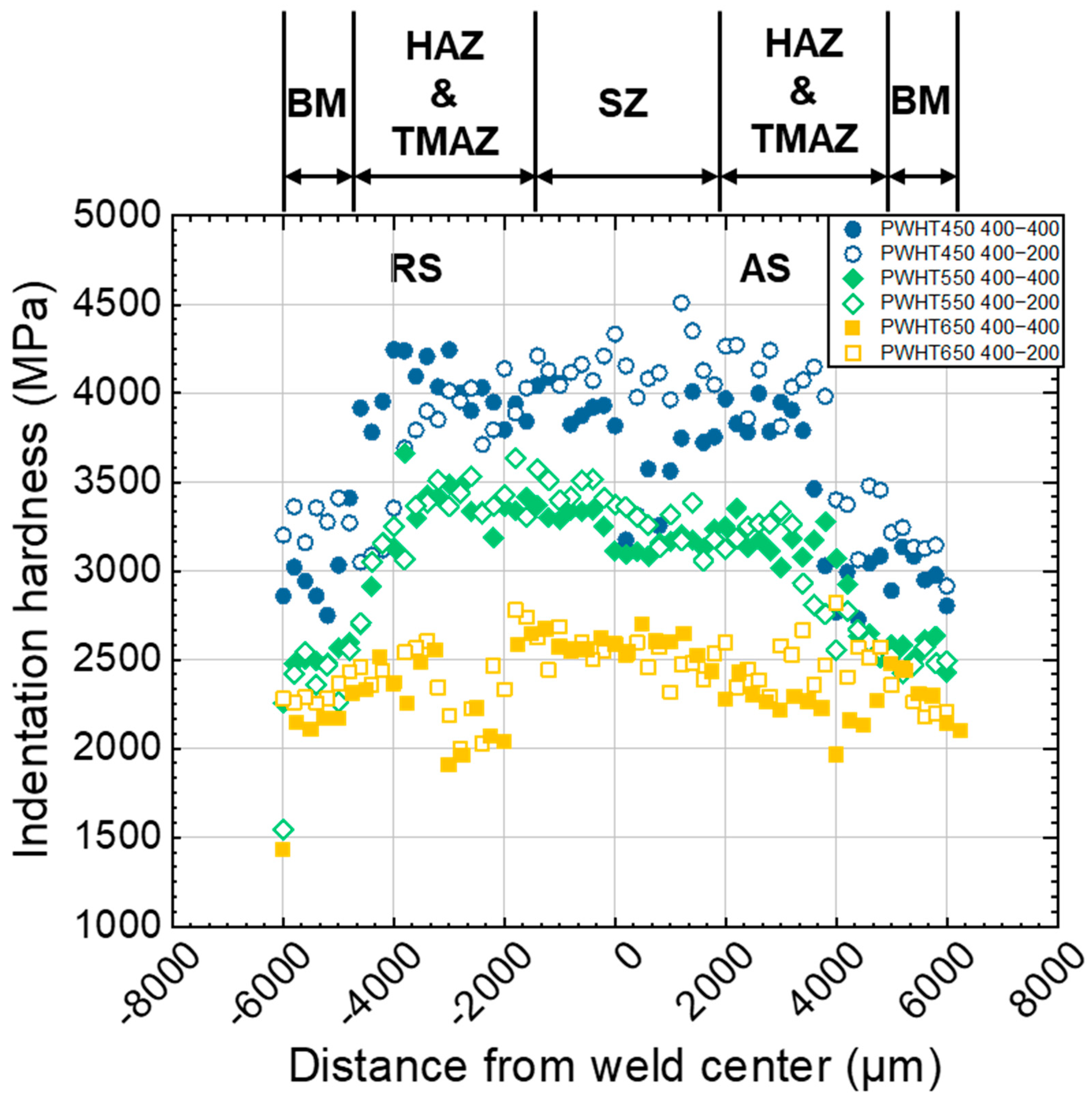
(5)
Local hardness mapping using nanoindentation revealed that hardness values continuously increased while getting close to SZ due to the increased fraction of the lath martensite phase. The increment in the hardness of RS was different from AS, which can be attributed to a difference in the heat input at both sides during the FSW process.

Author Contributions

U.M.C. and S.-C.H.: Investigation, Formal analysis, Data curation, Visualization, Writing—original draft. F.A.: Investigation. T.-S.J.: Supervision, Conceptualization, Writing—review & editing, Funding acquisition. All authors have read and agreed to the published version of the manuscript.

Funding

This work was supported by Research Assistance Program (2021) in the Incheon National University.

Institutional Review Board Statement

Not applicable.

Informed Consent Statement

Not applicable.

Data Availability Statement

Data are contained within the article.

Acknowledgments

The authors would like to thank Mun-Jin Kang and Jin-Young Yoon at Korea Institute of Industrial Technology for a support of FSW testing.

Conflicts of Interest

The authors declare no conflict of interest.

References

  1. Sun, Q.; Di, H.-S.; Li, J.-C.; Wang, X.-N. Effect of pulse frequency on microstructure and properties of welded joints for dual phase steel by pulsed laser welding. Mater. Des. 2016, 105, 201–211. [Google Scholar] [CrossRef]
  2. Mazaheri, Y.; Kermanpur, A.; Najafizadeh, A. A novel route for development of ultrahigh strength dual phase steels. Mater. Sci. Eng. A 2014, 619, 1–11. [Google Scholar] [CrossRef]
  3. Fillafer, A.; Werner, E.; Krempaszky, C. On phase transformation induced effects controlling the initial flow behavior of ferritic-martensitic dual-phase steels. Mater. Sci. Eng. A 2017, 708, 556–562. [Google Scholar] [CrossRef]
  4. Farias, F.; Balbi, M.; Batista, M.N.; Alvarez-Armas, I. Characterization of a Continuously Cooled Dual-Phase Steel Microstructure. Metall. Trans. A 2018, 49, 6010–6021. [Google Scholar] [CrossRef]
  5. Meng, Q.; Li, J.; Zheng, H. High-efficiency fast-heating annealing of a cold-rolled dual-phase steel. Mater. Des. 2014, 58, 194–197. [Google Scholar] [CrossRef]
  6. Shome, M.; Tumuluru, M. 1—Introduction to welding and joining of advanced high-strength steels (AHSS). In Welding and Joining of Advanced High Strength Steels (AHSS); Shome, M., Tumuluru, M., Eds.; Woodhead Publishing: Cambridge, UK, 2015; pp. 1–8. [Google Scholar]
  7. Alves, P.; Lima, M.; Raabe, D.; Sandim, H.R.Z. Laser beam welding of dual-phase DP1000 steel. J. Mater. Process. Technol. 2018, 252, 498–510. [Google Scholar] [CrossRef]
  8. Mishra, R.S.; Ma, Z. Friction stir welding and processing. Mater. Sci. Eng. R Rep. 2005, 50, 1–78. [Google Scholar] [CrossRef]
  9. Miles, M.; Nelson, T.; Steel, R.; Olsen, E.; Gallagher, M. Effect of friction stir welding conditions on properties and microstructures of high strength automotive steel. Sci. Technol. Weld. Join. 2009, 14, 228–232. [Google Scholar] [CrossRef]
  10. Jun, T.; Dragnevski, K.; Korsunsky, A. Microstructure, residual strain, and eigenstrain analysis of dissimilar friction stir welds. Mater. Des. 2010, 31, S121–S125. [Google Scholar] [CrossRef]
  11. Luckhoo, H.; Jun, T.-S.; Korsunsky, A. Inverse eigenstrain analysis of residual stresses in friction stir welds. Procedia Eng. 2009, 1, 213–216. [Google Scholar] [CrossRef] [Green Version]
  12. Ramana, G.V.; Yelamasetti, B.; Vardhan, T.V. Effect of FSW process parameters and tool profile on mechanical properties of AA 5082 and AA 6061 welds. Mater. Today 2021, 46, 826–830. [Google Scholar]
  13. Raval, S.K.; Judal, K. Recent Advances in Dissimilar Friction Stir Welding of Aluminum to Magnesium Alloys. Mater. Today 2020, 22, 2665–2675. [Google Scholar] [CrossRef]
  14. Nan, X.; Zhang, W.-D.; CAI, S.-Q.; Yue, Z.; Song, Q.-N.; Bao, Y.-F. Microstructure and tensile properties of rapid-cooling friction-stir-welded AZ31B Mg alloy along thickness direction. Trans. Nonferrous Met. Soc. China 2020, 30, 3254–3262. [Google Scholar]
  15. Han, G.; Lee, K.; Yoon, J.-Y.; Na, T.-W.; Ahn, K.; Kang, M.-J.; Jun, T.-S. Effect of post-weld heat treatment on mechanical properties of local weld-affected zones in friction stir welded AZ31 plates. Mater. Sci. Eng. A 2021, 805, 140809. [Google Scholar] [CrossRef]
  16. Wang, W.; Yuan, S.; Qiao, K.; Wang, K.; Zhang, S.; Peng, P.; Zhang, T.; Peng, H.; Wu, B.; Yang, J. Microstructure and nanomechanical behavior of friction stir welded joint of 7055 aluminum alloy. J. Manuf. Process. 2021, 61, 311–321. [Google Scholar] [CrossRef]
  17. Kim, Y.G.; Kim, J.S.; Kim, I.J. Effect of process parameters on optimum welding condition of DP590 steel by friction stir welding. J. Mech. Sci. Technol. 2014, 28, 5143–5148. [Google Scholar] [CrossRef]
  18. Matsushita, M.; Kitani, Y.; Ikeda, R.; Ono, M.; Fujii, H.; Chung, Y.D. Development of friction stir welding of high strength steel sheet. Sci. Technol. Weld. Join. 2011, 16, 181–187. [Google Scholar] [CrossRef]
  19. Mahmoudiniya, M.; Kokabi, A.H.; Goodarzi, M.; Kestens, L.A. Friction stir welding of advanced high strength dual phase steel: Microstructure, mechanical properties and fracture behavior. Mater. Sci. Eng. A 2020, 769, 138490. [Google Scholar] [CrossRef]
  20. Oliver, W.C.; Pharr, G.M. An improved technique for determining hardness and elastic modulus using load and displacement sensing indentation experiments. Mater. Res. 1992, 7, 1564–1583. [Google Scholar] [CrossRef]
  21. Xia, M.; Biro, E.; Tian, Z.; Zhou, Y.N. Effects of Heat Input and Martensite on HAZ Softening in Laser Welding of Dual Phase Steels. ISIJ Int. 2008, 48, 809–814. [Google Scholar] [CrossRef] [Green Version]
  22. Zhang, J.; Di, H.; Deng, Y.; Misra, R. Effect of martensite morphology and volume fraction on strain hardening and fracture behavior of martensite–ferrite dual phase steel. Mater. Sci. Eng. A 2015, 627, 230–240. [Google Scholar] [CrossRef]
  23. Ashrafi, H.; Shamanian, M.; Emadi, R.; Ahl Sarmadi, M. Comparison of Microstructure and Tensile Properties of Dual Phase Steel Welded Using Friction Stir Welding and Gas Tungsten Arc Welding. Steel Res. Int. 2018, 89, 1700427. [Google Scholar] [CrossRef]
  24. Ghassemi-Armaki, H.; Maaß, R.; Bhat, S.P.; Sriram, S.; Greer, J.R.; Kumar, K.S. Deformation response of ferrite and martensite in a dual-phase steel. Acta Mater. 2014, 62, 197–211. [Google Scholar] [CrossRef]
Figure 1. (a) The schematics showing the overall FSW process and the tensile sample configuration, (b) high and low magnification SEM micrographs of the BM, and (c) top and transverse view of FSW400-200 and FSW400-400 samples.
Metals 11 01097 g001
Figure 2. The optical micrograph and SEM images showing the (a) BM, (b) TMAZ, (c) SZ of the FSW400-200 and (d) BM, (e) TMAZ, (f) SZ of the FSW400-400 samples.
Metals 11 01097 g002
Figure 3. (a) The microhardness profile and (b) cross-sectional local hardness maps (4 × 60 = 240 indent matrix with a spacing of 250 μm and a maximum depth of 1.5 μm) for the joint in the FSW400-200 and FSW400-400. The black and white arrows correspond to the area of the softening HAZ.
Metals 11 01097 g003
Figure 4. The engineering stress-strain curves of as received DP780 steel and FSWed samples.
Metals 11 01097 g004
Figure 5. Cross-sectional contour maps of the strain distribution during the tensile test with the DIC technique concerning to strain levels.
Metals 11 01097 g005
Figure 6. (a) The microstructure showing the interfaces between SZ, TMAZ, and HAZ for the FSW400-400 and (b) grain growth in the microstructure for FSW400-400 sample subjected to the post-weld heat treatment at 650 °C.
Metals 11 01097 g006
Figure 7. Representative stress-strain curves of the samples subjected to subsequent annealing with different temperatures of (a) 450 °C, (b) 550 °C, and (c) 650 °C.
Metals 11 01097 g007
Figure 8. Cross-sectional contour maps of the strain distribution during the tensile test with the DIC: the FSW400-400 and 400-200 samples which were subjected to subsequent annealing at different temperatures of (a) 450 °C, (b) 550 °C, and (c) 650 °C for 1 h.
Metals 11 01097 g008
Figure 9. Hardness profiles of the FSWed joint at different annealing temperatures. The section of the joint areas represented above is based on macrostructural observation via OM.
Metals 11 01097 g009
Table 1. Chemical composition (wt.%) of DP780 steel.
GradeCMnSiPSFe
DP7800.122.60.60.030.003Bal.
Table 2. FSW parameters used for the current study.
WeldsWelding Condition
DP780
(t = 1.4 mm)
Tool rotation speedTool welding speedTilt angleForce
400 rpm200 mm/min2 kN
400 rpm400 mm/min
Table 3. Tensile properties of DP 780 steel and FSWed joints.
Sampleσ0.2 (MPa)σUTS (MPa)εu (%)εT (%)
DP78052681516.423.6
FSW400-2006978843.94.3
FSW400-4007608845.57.8
Table 4. Resultant tensile properties of FSWed DP780 with different annealing temperatures.
Sampleσy (MPa)σUTS (MPa)εu (%)εT (%)
PWHT 450-425756754.47.2
PWHT 450-445846976.08.8
PWHT 550-424795786.910.4
PWHT 550-4448260911.116.7
PWHT 650-424244555.59.7
PWHT 650-444414574.56.0
Publisher’s Note: MDPI stays neutral with regard to jurisdictional claims in published maps and institutional affiliations.

