Article

Comparative Study of the Metallurgical Quality of Primary and Secondary AlSi10MnMg Aluminium Alloys

by
Asier Bakedano
1,
Andrea Niklas
1,
Ana Isabel Fernández-Calvo
1,
Gorka Plata
2,
Jokin Lozares
2 and
Carlos Berlanga-Labari
3,*
1
AZTERLAN, Basque Research and Technology Alliance (BRTA), 20850 Durango, Spain
2
Mechanical and Manufacturing Department, Mondragon Unibertsitatea, Loramendi 4, 20500 Mondragon, Spain
3
Engineering Department, Institute for Advanced Materials and Mathematics (INAMAT2), Public University of Navarre, 31006 Pamplona, Spain
*
Author to whom correspondence should be addressed.
Metals 2021, 11(7), 1147; https://doi.org/10.3390/met11071147
Submission received: 15 June 2021 / Revised: 13 July 2021 / Accepted: 16 July 2021 / Published: 20 July 2021
(This article belongs to the Section Metal Casting, Forming and Heat Treatment)

Abstract

:
The use of secondary aluminium is increasingly being promoted in the automotive industry for environmental reasons. The purpose of this study was to demonstrate that it is possible to obtain a recycled AlSi10MnMg(Fe) aluminium alloy with equal metallurgical quality to that of a primary AlSi10MnMg alloy when an adequate melt treatment is applied. The melt treatment consisted of deoxidation, degassing and skimming in accordance with the detailed procedure described in this article. The metallurgical qualities of one primary and two secondary alloys were assessed using thermal analysis, the density index test, the macroinclusion test and the microinclusion level test before and after melt treatment. The thermal analysis allowed us to compare the variables of the solidification cooling curve (Al primary temperature and its undercooling; Al-Si eutectic temperature and its predictive modification rate). The density index test was used to evaluate the hydrogen gas content in the melt. The macroinclusion test was used to evaluate the melt cleanliness, while the microinclusion level test was used to perform the inclusion identification and quantification analyses. This study showed the feasibility of manufacturing structural components using 100% recycled secondary aluminium alloy through V-HPDC technology.

1. Introduction

The primary aluminium alloy AlSi10MnMg is the most widely used alloy for manufacturing structural components in the automotive market, such as front shock towers, door frames and rear longitudinal members. Up to 80% of the aluminium structural components made through vacuum high-pressure die casting (V-HPDC) are produced using this alloy [1]. The main reasons for its use are the design freedom (variations in the wall thicknesses), functional integration (ability to integrate different functions into the same component), cost efficiency (mass production for complex components), weight-reduction potential (very thin and low density) and the wide range of mechanical properties achieved using adequate heat treatment [2]. The main differences between the components of conventional high-pressure die casting (HPDC) technology and V-HPDC technology are the ductility or energy absorption capacity [3] and the ability of the latter to be heat-treated and welded [4,5]. The ductility obtained from parts cast by V-HPDC is significantly higher than that of conventional HPDC technology. Considering the UNE-EN-1706:2020 standard as a reference, the minimum elongation required for the AlSi9Cu3(Fe)(Zn) alloy (the most used secondary alloy in conventional HPDC process [6,7,8]) is 1% in the F state, whereas for a V-HPDC component cast in AlSi10MnMg, a minimum elongation of 12% is required after T7 heat treatment [3,4,5,6,7]. This huge difference in elongation is associated with the different compositions and microstructures of both alloys, with the higher melt cleanliness [9,10] and the lower porosity being achieved using vacuum application in V-HPDC. The primary aluminium AlSi10MnMg alloy, which generally has a low iron content (lower than 0.25 wt.%), shows a globular modified Si eutectic alongside aluminium primary dendrites. Intermetallic Al12Mn3Si3 phases in the eutectic area with polygonal–globular shapes are also observed. In the F conditions (the as-cast state), Mg2Si intermetallic phases are present in the microstructure. These Mg2Si phases are dissolved and then finely precipitated in the aluminium matrix after applying T6 or T7 heat treatments consisting of the solution treatment, quenching and artificial aging treatment [11,12,13,14]; however, the microstructure of the secondary AlSi9Cu3(Fe)(Zn) alloy with high iron content (usually between 0.7 and 1.1 wt.%) is mainly characterised by an unmodified eutectic silicon. The intermetallic iron phases have two different shapes: polygonal-polyhedral or Chinese script denominated by α-phases or π-phases (depending on the chemical composition and reactions). The plate phases are denominated by β-phases (β-Al5FeSi). These β-phases are more harmful due to their brittle shape and they significantly reduce the mechanical properties, especially the ductility [15,16,17,18,19]. Different strategies are used to neutralise the effects of the harmful β-phases, such as the addition of Mn, Cr, V, Be or Sr in the melt to modify the β-plates phases by iron phases with a less harmful morphology [20,21,22,23,24,25,26]; however, the area fraction of intermetallic compounds should also be kept low; thus, to achieve good ductility, a maximum of 0.6–0.7 Fe content is prescribed [24,25].
Innovative secondary aluminium alloys could be used to find comparable mechanical properties to the corresponding primary alloy [11,25,27], with lower costs, energy savings and finally less CO2 emissions compared to primary aluminium alloy production [28]; however, the use of secondary alloys and their applications are significantly affected by the melt cleanliness [29,30]. A proper melt treatment improves the aluminium melt quality, with little capital investment and without major changes to the shop floor. The deoxidation, skimming and degassing processes show significant improvements over untreated melt samples [31].
The aim of this work is to demonstrate that if an adequate melt treatment is applied, it is possible to obtain a recycled AlSi10MnMg(Fe) aluminium alloy with equal metal cleanliness to the primary AlSi10MnMg alloy. The new secondary AlSi10MnMg(Fe) developed in a previous study with 0.6 wt.% Fe and 0.4 wt.% Mn, which demonstrated similarly high mechanical properties to that of a primary AlSi10MnMg alloy, was selected for this study [11]. The thermal analysis, density index and macroinclusion and microinclusion levels before and after the melt treatment in both the primary and the recycled AlSi10MnMg aluminium were investigated to evaluate the effects of the melt treatment in terms of melt cleanliness in both alloys. Regarding the secondary aluminium, two tests were performed: (1) with the raw material coming from a remelter plus alloying adjustments; (2) with new scrap materials from different foundries plus alloying adjustments.

2. Materials and Methods

Three different alloys were melted with the following main raw materials, as shown in Figure 1: (a) primary ASi10MnMg ingots from Rheinfelden; (b) secondary ASi10MnMg(Fe) ingots from a local remelter; (c) new scrap (clean scrap from the secondary alloy) materials sourced from the manufacturing processes from two foundries.
For each experiment, 40–45 kg of each alloy was melted at 725 °C in an electric furnace with a capacity of 60 kg. After melting, simple skimming was performed on the surface of the melt before taking the different melt samples. To achieve the target composition in terms of Si, Fe, Mn, Mg and Sr for the secondary alloy [11], less than 200 g of each alloying element was added. Si and Mg were added as pure elements, along with AlFe45 alloy (45 wt.% Fe), AlMn20 (20 wt.% Mn) and AlSr10 (10 wt.% Sr). Three samples were taken from each alloy before and after the melt treatment to perform the thermal analysis, the density index test, the macroinclusion test using Alu Q® melt quality assessment equipment and the microinclusion level test using porous filtration tests. The test procedures followed in each case are described below.
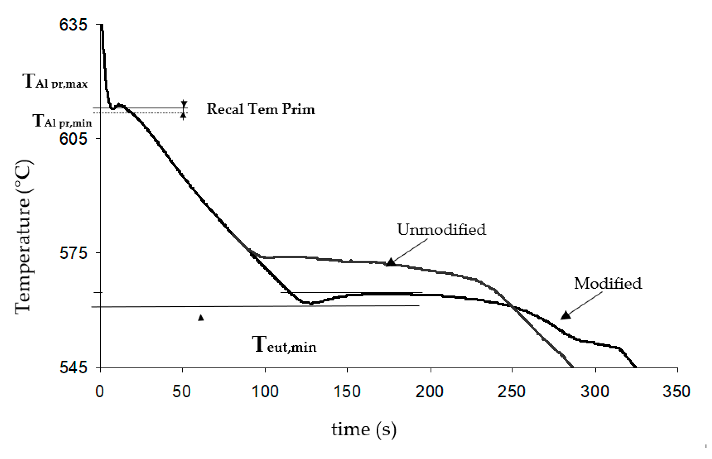
Thermal analysis test: The cooling curve was plotted and analysed using Thermolan®-Al software (Fundacion Azterlan, Durango, Spain). The thermocouples were located at the centre of the metallic mould with a diameter of 40 mm and length of 35 mm. The main thermal analysis parameters were measured, including the minimum temperature of the primary aluminium (TAl pr min), its recalescence temperature (RecalTem Prim) and the minimum Al-Si eutectic temperature (Teut min), as shown in Figure 2. The software predicted the modification rate based on the model developed in Azterlan for V-HPDC AlSi10MnMg alloys.
Density index test: One sample was solidified under a reduced pressure of 80 mbar (RPT), while another sample was solidified under atmospheric pressure. The density index (D.I.) was calculated according to Equation (1):
D . I . =   ρ atm .   ρ RTP .     ρ atm   ×   100
where ρatm. is the density of the sample measured at atmospheric pressure and ρRTP is the density of the sample solidified under 80 mbar.
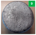
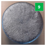
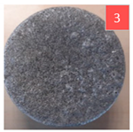
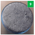
Macroinclusion Test: The melt sample was solidified in a vacuum at 5 mbar and the macroinclusions floated to the surface of the sample. The sample surface was evaluated by visual comparison with the images in a standard gallery with a range of inclusion content levels (macroinclusion level chart, see Figure 3) and was rated on a scale from 1 (worst) to 10 (best cleanliness degree).
Microinclusion level: The melt was cast into a crucible of about 2 kg capacity and the aluminium went through a filter using a vacuum system at 150 mbar (similar to PodFA). Subsequently, the metal that remained unfiltered was analysed (metal that does not pass through the filter is where all of the impurities are deposited). The inclusions observed in the filter were analysed by optical and scanning electron microscopy to identify and quantify the amounts of microinclusions in the melt.
After taking the samples in order to characterise the melt quality, the melt treatment was performed using the following instructions: Keep the melt at 725–730 °C, then add 100 g of Elimoxal KF20 (a deslagging, deoxidising and covering flux) on the surface of the melt. Perform the first degassing and cleaning treatment for the melt with a rotor impeller with Ar (rotational speed: 50 rpm; Argon flux: 8 L/min) for 10 min. Skim and remove all slag from the melt surface. Load 100 g of master alloy AlSr10 in cut rod format, perform the second degassing and cleaning treatment for the melt with the rotor at the same rotational speed and Argon flux in the same way as the previous treatment for 15 min, then skim and remove all slag form the surface. The same melt treatment was performed for all three different alloys and samples were taken to characterise the melt quality of each alloy after the melt treatment.
The chemical compositions of the three alloys were analysed on a Spectrolab spark spectrometer and are presented in Table 1.

3. Results and Discussion

The experimental results in terms of the metallurgical quality were determined via the different tests performed. The alloys used for this work had the chemical compositions shown in Table 1. The AlSi10MnMg primary alloy showed a very low content of Fe, as well as low values of the other impurities, such as Cu and Zn. Both secondary alloys had similar chemical compositions, which were very similar to the secondary alloy with a medium content of Mn. In comparison to the primary alloy, they presented higher contents of Fe with moderate contents of Mn and slightly higher contents of Cu and Zn. The three alloys showed quite similar Sr yields with the addition of the AlSr10 master alloy.
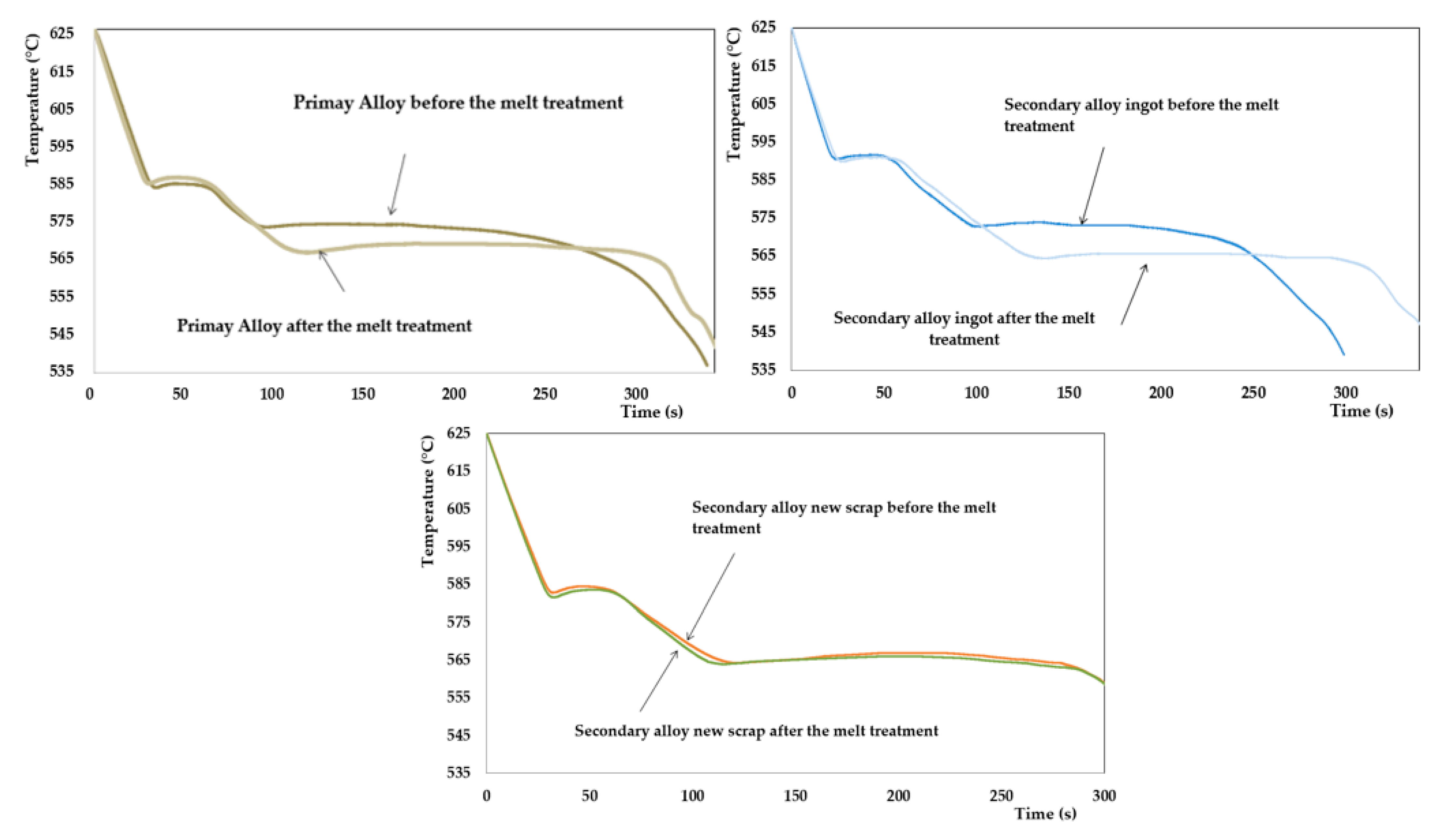
The cooling curve of the three alloys is shown in Figure 4, while the main parameters of each cooling curve are summarised in Table 2. The secondary alloy made from new scrap presented a lower minimum temperature for the primary aluminium because it had the highest Si content out of the three alloys analysed. The primary recalescence values for the aluminium samples varied between 1.1 and 1.8 °C, indicating a large grain size in the analysed cup [32]. This is consistent with the absence of an addition of Ti refiners. It should be noted that the solidification rate in V-HPDC is so high that natural grain refinement is achieved, meaning no grain refinement is recommended in this process.
The effect of adding AlSr10 into the melt treatment significantly reduces the aluminium–silicon eutectic temperature in the primary alloy and the secondary alloy made from the ingots, as shown in Table 2. The modification rates predicted by Thermolan® improved from 1–2 to 4 with the addition of AlSr10 in both alloys; however, the secondary alloy made from the new scrap had the same eutectic temperature and the same high predicted modification rate both before and after the melt treatment. The Sr content at 0.010 wt.% before the melt treatment was high enough to achieve a good modification rate in V-HPDC [10].
The results of the density analysis obtained during the experiment for the different aluminium alloys and the different stages (before and after the melt treatment) are depicted in Figure 5. The density index of the primary aluminium alloy was significantly lower than that obtained for both secondary aluminium alloys before the melt treatment. As such, a significantly lower hydrogen content in the melt was expected in this condition; however, after the melt treatment, there were no significant differences among the three alloys, showing that the melt treatment is highly effective at reducing the content of hydrogen in the melt below 1% in D.I., as proposed by Roos et al. [33].
The results of the macroinclusion test for the different alloys and stages are shown in Table 3, classified using a naked eye comparison with the chart in Figure 3, as described in the experimental procedure. Before the melt treatment, the levels of macroinclusions were significantly lower in the secondary alloys, with the new scrap alloy being the worst sample; however, after the melt treatment, the aluminium quality improved significantly and the macroinclusion contents in the three different alloys reached very low levels.
The samples in the microinclusion tests were cut and a metallographic analysis was performed on the polished surfaces close to the ceramic filter where the inclusions were located. Three main areas were observed in the inspection field for the different alloys and stages: the ceramic filter area (1); the inclusion cake (2); the base metal area (3). The filtered melt showed very similar results in all trials, being significantly higher than 500 g, which is considered the minimum required value for PodFA analysis [34].
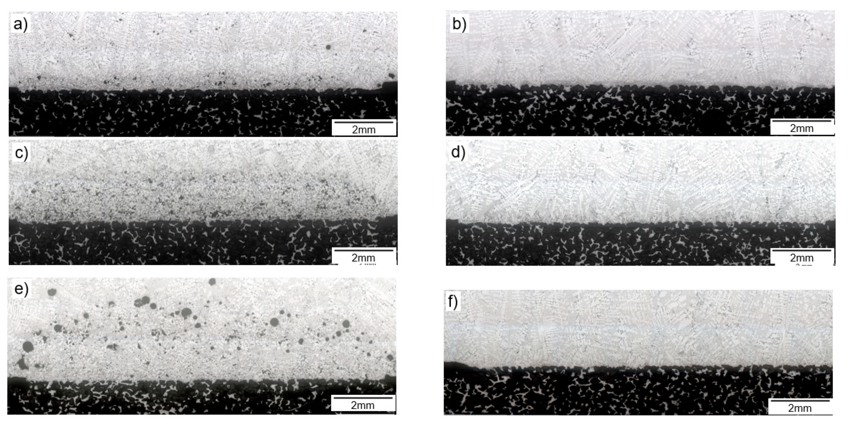
During the experiment, the different filtered and unfiltered weights were measured as shown in Table 4. The thickness of the inclusion cake is shown in Figure 6 and its measurement is summarised in Table 5. Before the melt treatment, the best result was for the primary alloy with 472 µm, followed by the secondary alloy made from ingots with 1660 µm (more than three times the best result) and finally the secondary alloy made from new scrap with 2766 µm; however, after applying adequate melt treatment, the thicknesses of the inclusion cakes were reduced significantly in the three aluminium alloys, especially in the secondary aluminium alloys, the thicknesses of which were lower than 80 µm.
The samples were analysed using optical microscopy and SEM, as shown in Figure 7.
The results of this microscopy analysis based on the identification and quantification of the microinclusions are shown in Figure 8.
Regarding the quantification of the inclusions, the contents of microinclusions were significantly worse in the secondary alloys than in the primary alloy before the melt treatment, with the secondary new scrap alloy having a total inclusion content of 0.69 mm2/kg, which was the worst value. The differences between the inclusion contents were mainly seen in the large magnesium oxides and spinel MgAl2O4 inclusions. Dispersed MgO inclusions were also observed in the secondary alloy made from new scrap; however, the oxide film contents were similar in all aluminium alloys (the primary alloy had 275 oxides per kg, the secondary alloy from ingots had 295 per kg and finally the secondary alloy made from new scrap had 300 per kg). After the melt treatment, the aluminium melts significantly improved the microinclusion levels in all three alloys, with very similar levels seen for all of them (with microinclusion levels lower than 0.1 mm2/kg and oxide films lower than 10 per kg; surprisingly, the primary allow from ingots had the highest value).

4. Conclusions

The melt quality levels of one AlSi10Mn primary alloy and of two secondary alloys obtained from different raw materials (the ingots from a remelter and new scrap from two different foundries) were analysed using an Alu Q® system and microinclusion tests before and after the melt treatment. The main conclusions are summarised below.
  • After adding the AlSr10 master alloy, the eutectic temperatures of the three alloys were reduced significantly, achieving similar values, dropping from 573.2–573.0 °C to 566.5–563.9 °C. Additionally, high modification rates (4 on a scale of 1 to 6) were predicted for the three cases, achieving optimal metallurgical quality;
  • Density index test: Before the melt treatment, the best value was achieved for the primary aluminium alloy, which was significantly higher than for the rest of the alloys. After the melt treatment, the density index values were very similar (primary alloy D . I .   = 0.6%; secondary alloy from ingots D . I .   = 0.5%; secondary alloy made from new scrap D . I .   = 0.5%) and fulfilled the requirement of D . I .   < 1%;
  • The primary alloy was the cleanest in the macroinclusion and microinclusion tests before the melt treatment in comparison with the two secondary alloys, with the alloy from new scrap being the worst. After the melt treatment, the macroinclusion and the microinclusion levels were very similar in all three alloys. The macroinclusion levels were certainly very good, with all alloys showing a value of 9 on a scale of 1 to 10. In terms of the microinclusion level, the melt fulfilled the requirements of the inclusion content being lower than 0.1 mm2/kg and the oxide film amounting to less than 10 units per kg in the three alloys.
The main conclusion is that if an adequate melt treatment is applied, the structural material quality of raw aluminium with a low modification rate, high dissolved hydrogen content and high macro- and microinclusion accumulation can be renewed. The following values for unwanted characteristics were proven to be fixable:
  • Modification rates of 1 were increased to 4 via chemical composition adjustment of Sr;
  • Density indexes of 10.1% can be brought down to 0.5% by degassing the melt using Ar rotor technology;
  • Macroinclusion levels of 3 can be improved to 9 using Ar rotor technology and flux-aided floatation and skimming;
  • The microinclusion film content can be reduced from 300 units/kg to less than 10 units/kg and from 0.69 mm2/kg to 0.01 mm2/kg using Ar rotor technology and flux-aided floatation and skimming.
A recycled aluminium alloy (AlSi10MnMg(Fe)) equal to the primary AlSi10MnMg alloy can be achieved, irrespective of the raw materials used, even if ingots from a remelter or new scrap are used; therefore, this study demonstrates the feasibility of manufacturing structural components using 100% secondary aluminium alloy from new scrap.

Author Contributions

Conceptualisation, A.B. and A.I.F.-C.; methodology, G.P. and J.L.; validation, A.N. and C.B.-L.; formal analysis, A.N.; investigation, A.B.; writing—review and editing, A.B., A.N. and A.I.F.-C.; supervision, C.B.-L. All authors have read and agreed to the published version of the manuscript.

Funding

This research was partially supported by the Basque Government’s Elkartek Tipo2 Programme managed by Spri under grant agreement no. Elkartek2019 (KK-2019/00080) from Innproal. The Alu Q® development was supported partially by funding received as part of the REVaMP project from the European Union’s Horizon 2020 research and innovation programme under grant agreement No. 869882.

Institutional Review Board Statement

Not applicable.

Informed Consent Statement

Not applicable.

Data Availability Statement

Not applicable.

Acknowledgments

The authors thank all of the Innproal project partners for their advice and collaboration, namely CIE Automotive and Mondragon Unibertsitatea. The authors also thank their colleagues Rodolfo González, Clara Delgado, Ibon Lizarralde, Sergio Orden and Emili Barbarias as part of the Azterlan Light Materials team.

Conflicts of Interest

The authors declare no conflict of interest.

References

  1. Luszczak, M. Development of High Pressure Die Casting Structural Components at Nemak Poland. In Proceedings of the 2nd International Forum: Vacuum Die Casting: Structural Parts, Territet Montreux, Fondarex, Switzerland, 25 March 2015. [Google Scholar]
  2. Menk, W. Automotive components in Al High Pressure Die Casting: Light weight challenge and material development. In Proceedings of the 3rd International Technical Forum on the HPDC Technology, Amorebieta, Spain, 26 November 2015. [Google Scholar]
  3. Rheinfeldeng Alloys GmbH & Co. KG. Handbuch Primary Aluminium Casting Alloys; Rheinfeldeng Alloys GmbH & Co. KG: Rheinfelden, Germany, 2010. [Google Scholar]
  4. Cecchel, S.; Ferrario, D.; Panvini, A.; Cornacchia, G. Lightweight of a cross beam for commercial vehicles: Development, testing and validation. Mater. Des. 2018, 149, 122–134. [Google Scholar] [CrossRef]
  5. Teichmann, F.; Ziemer, A.; Leitner, M.; Hensel, J.; Dilger, K. Linear Elastic FE-Analysis of Porous, Laser Welded, Heat Treatable, Aluminium High Pressure Die Castings based on X-Ray Computed Tomography Data. Materials 2020, 13, 1420. [Google Scholar] [CrossRef] [Green Version]
  6. Dobrzański, L.A.; Maniara, R.; Sokolowski, J.H. The effect of cast Al-Si-Cu alloy solidification rate on alloy thermal characteristics. J. Achiev. Mater. Manuf. Eng. 2006, 17, 217–220. [Google Scholar]
  7. Salas, A.E.; Altamirano Guerrero, R.G.; Rodríguez Ortiz, G.; Reyes Gasga, J.; García Robledo, J.F.; Lozada Flores, O.; Sheilla Costa, P. Microstructural, microscratch and nanohardness mechanical characterization of secondary commercial HPDC AlSi9Cu3-type alloy. J. Mater. Res. Technol. 2020, 9, 8266–8282. [Google Scholar] [CrossRef]
  8. Hu, X.P.; Fang, L.; Zhou, J.X.; Zhang, X.Z.; Hu, H. Characterization and kinetic modeling of secondary phases in squeeze cast Al alloy A380 by DSC thermal analysis. China Foundry 2017, 14, 98–107. [Google Scholar] [CrossRef] [Green Version]
  9. Niklas, A.; Bakedano, A.; Orden, S.; Da Silva, M.; Nogues, E.; Fernandez-Calvo, A.I. Effect of microstruture and casting defects on the mechanical properties of secondary AlSi10MnMg(Fe) test parts manufactured by vacuum assisted high pressure die casting technology. Mater. Today Proc. 2015, 2, 4931–4938. [Google Scholar] [CrossRef]
  10. Rheinfeldeng Alloys GmbH & Co. KG. Handbuch Druckguss Sf-36 Ci-37 Ma-59 Ma-33; Rheinfeldeng Alloys GmbH & Co. KG: Rheinfelden, Germany, 2007. [Google Scholar]
  11. Niklas, A.; Bakedano, A.; Orden, S.; Da Silva, M.; Nogues, E.; Fernandez-Calvo, A.I. Microstructure and Mechanical properties of a new secondary AlSi10MnMg(Fe) alloy for ductile high pressure die casting parts for the automotive industry. Key Eng. Mater. 2016, 710, 244–249. [Google Scholar] [CrossRef]
  12. Gustafsson, G.; Thorvaldsosson, T.; Dunlop, G.L. The influence of Fe, Mn and Cr on the microstructures of cast Al-Si alloys. Metall. Trans. 1986, 17A, 45–52. [Google Scholar] [CrossRef]
  13. Trimal®-05 The High Pressure Die Casting Alloy for Crash Relevant Application. Trimet Aluminium Ag. Available online: https://www.bohaitrimet.com/fileadmin/user_upload/AGB_Downloads/product-sheet_trimal-05_gb.pdf (accessed on 27 May 2021).
  14. Rheinfeldeng Alloys GmbH & Co. KG. Optimizing the Mn and Mg content for structural application Silafont®-36, AlSi9MgMn. In Proceedings of the 22nd Internationational Die Casting Congress and Exposition by NADCA, Indianapolis, Indiana, 15–17 September 2003. [Google Scholar]
  15. Seifeddine, S.; Svensson, I.L. The influence of Fe and Mn content and cooling rate on the microstructure and mechanical properties of A380-die casting alloys. Metall. Sci. Technol. 2009, 27, 11–13. [Google Scholar]
  16. Backerud, S.L.; Chai, G.; Tamminen, J. Solidification Characteristics of Aluminium Alloys. AFS 1990, 2, 71–84. [Google Scholar]
  17. Lu, L.; Dahle, A.K. Iron-rich intermetallic phases and their role in casting defect formation in hypoeutectic Al-Si alloys. Metall. Mater. Trans. 2005, 36, 819–835. [Google Scholar]
  18. Gowri, S.; Samuel, F.H. Effect of alloying elements on the solidification characteristics and microstructure of Al-Si-Cu-Mg-Fe 380 alloy. Metall. Mater. Trans. 1994, 25, 437–448. [Google Scholar] [CrossRef]
  19. Samuel, A.M.; Samuel, F.H.; Villeneuve, C.; Doty, H.W.; Valtierra, S. Effect of trace elements on β-Al5FeSi characteristics, porosity and tensile properties of Al-Si-Cu (319) cast alloys. Int. J. Cast Met. Res. 2001, 14, 97–120. [Google Scholar] [CrossRef]
  20. Shabestari, S.G. The effect of iron and manganese on the formation of intermetallic compounds in aluminium–silicon alloys. Mater. Sci. Eng. A 2004, 383, 289–298. [Google Scholar] [CrossRef]
  21. Ashtari, P.; Tezuka, H.; Sato, T. Influence of Sr and Mn Additions on Intermetallic Compound Morphologies in Al-Si-Cu-Fe Cast Alloys. Mater. Trans. 2003, 44, 2611–2616. [Google Scholar] [CrossRef] [Green Version]
  22. Shabestari, S.G.; Gruzleski, J.E. Gravity segregation of complex intermetallic compounds in liquid aluminium-silicon alloys. Metall. Mater. AFS Trans. 1995, 26, 999–1006. [Google Scholar] [CrossRef]
  23. De la Fuente, E.; Alfaro, I.; Niklas, A.; Anza, I.; Fernández-Calvo, A.I. Improved microstructure and mechanical properties of a recycled AlSi7Mg 0.3 alloy with 0.3 wt.% Fe by small additions of Mn, Cr and V. In Proceedings of the 48th Aluminium Two Thousand Congress, Milan, Italy, 14–18 May 2013. [Google Scholar]
  24. Niklas, A.; González-Martínez, R.; Orden, S.; Bakedano, A.; Garat, M.; Fernández-Calvo, A.I. Effect of Wall Thickness and Manganese Additions on the formation of intermetallic iron phases in new secondary alloys suitable for vacuum assisted HPDC. In Proceedings of the 121st Metalcasting Congress, Milwaukee, WI, USA, 25–27 April 2017. [Google Scholar]
  25. Fernández, A.I.; Niklas, A.; Alfaro Abreu, I.; Anza Ortiz de Apodaca, I. Method for Obtaining Improved Mechanical Properties in Recycled Aluminium Casting Free of Platelet-Shaped Beta-Phases. Granted Patent EP 2471967B1, 28 December 2010. [Google Scholar]
  26. Anantha Narayanan, L.; Samuel, J.E.; Gruzleski, J.E. Crystallization behavior of iron-containing intermetallic compounds in 319 aluminium alloy. Metall. Mater. Trans. A 1994, 25, 1761–1773. [Google Scholar] [CrossRef]
  27. Hurtalova, L.; Tillova, E.; Chalupova, M. Microstructural and Vicker Microhardness Evolution of Heat Treated Secondary Aluminium Cast Alloy. Key Eng. Mater. 2013, 586, 137–140. [Google Scholar] [CrossRef]
  28. Das, K.S.; Gren, J.A.S. Aluminium Industry and Climate Change-Assessment and Responses. J. Miner. Met. Mater. Soc. 2010, 62, 27–31. [Google Scholar] [CrossRef]
  29. Soo, V.K.; Peeters, J.; Paraskevas, D.; Compston, P.; Doolan, M.; Duflou, J.R. Economic and Environmental Evaluation of Alu-minium Recycling based on a Belgian Case Study. In Proceedings of the 16th Global Conference on Sustainable Manufacturing, Lexington, KY, USA, 4 October 2018. [Google Scholar]
  30. Soo, V.K.; Peeters, J.; Paraskevas, D.; Compston, P.; Doolan, M.; Duflou, J.R. Sustainable aluminium recycling of end-of-life products: A joining techniques perspective. J. Clean. Prod. 2018, 178, 119–132. [Google Scholar] [CrossRef] [Green Version]
  31. Wetzel, C.S. Benchmarking Melting. Mod. Cast. 2012, 102, 18–21. [Google Scholar]
  32. Niklas, A.; Abaunza, U.; Fernández-Calvo, A.I.; Lacaze, J.; Suarez, R. Thermal analysis as a microstructure prediction tool for A356 aluminium parts solidified under various cooling conditions. In Proceedings of the 69th World Foundry Congress (WFC), Hangzhou, China, 20 October 2010. [Google Scholar]
  33. Roos, H. Optimization of the HPDC process. In Proceedings of the Technical Forum Buhler, Madrid, Spain, 18 October 2016. [Google Scholar]
  34. Brochure—PoDFA. The Complete Solution for Inclusion Measurement|Inclusion Identification and Quantification Analysis. ABB Inc. Process Automation Measurement & Analytics. Available online: https://library.abb.com/es/results (accessed on 9 June 2021).
Figure 1. Raw aluminium materials used for the experiment: (a) primary AlSi10MnMg ingots; (b) secondary AlSi10MnMg(Fe) ingots; (c) new scrap for secondary AlSi10MnMg(Fe) preparation.
Metals 11 01147 g001
Figure 2. Example of the cooling curve with definitions of the critical parameters.
Metals 11 01147 g002
Figure 3. Macroinclusion level chart for the determination of the inclusion rating level in the melt (macroinclusion analysis).
Metals 11 01147 g003
Figure 4. The cooling curves for the different alloys before and after the melt treatment.
Metals 11 01147 g004
Figure 5. Density index values for the three alloys at different stages (before and after the melt treatment).
Metals 11 01147 g005
Figure 6. The inclusion cakes used for the different alloys: (a) before and (b) after the melt treatment for the primary alloy sample; (c) before and (d) after the melt treatment for the secondary alloy sample made from ingots; (e) before and (f) after the melt treatment for the secondary alloy sample made from new scrap.
Metals 11 01147 g006
Figure 7. (a) Microinclusion identification using SEM analysis of the primary alloy before the melt treatment: (1) oxides films γ-Al2O3; (2) carbides Al4C3; (3) large magnesium oxides and spinel MgAl2O4; (4) oxides and others (α-Al2O3, CaO, and SiO2); (5) grain refinement particles TiB2 and (Ti, V)B2; (b) EDS analysis of the main oxide.
Metals 11 01147 g007
Figure 8. Quantification of each microinclusion identified in the different alloys before and after the melt treatment.
Metals 11 01147 g008
Table 1. Chemical compositions of the different aluminium samples tested in this study before and after the melt treatment (wt.%).
ReferenceStagesSiFeCuMnMgCrZnTiSr
Primary alloy
AlSi10MnMg
Before melt treatment10.60.110.010.540.290.0010.0120.0680.006
After melt treatment10.60.120.010.530.300.0010.0120.0720.015
Secondary alloy
AlSi10MnMg(Fe) from ingots
Before melt treatment9.670.620.030.420.35<0.010.0150.053<0.005
After melt treatment9.900.640.030.420.34<0.010.0150.0520.013
Secondary alloy
AlSi10MnMg(Fe) from new scrap
Before melt treatment11.00.620.040.450.51<0.010.0210.0760.010
After melt treatment10.80.610.040.430.52<0.010.0200.0730.018
Table 2. The main cooling curve parameters and modification rate predictions for Themolan®-Al for V-HPDC AlSi10MnMg alloys.
ReferenceStagesTAl Prim min (°C)Recal Prim (°C)TEutec min (°C)Modification Rate Prediction
Primary alloyBefore melt treatment586.61.1573.21–2
After melt treatment584.71.5566.54
Secondary alloy from ingotsBefore melt treatment590.51.1573.01–2
After melt treatment590.11.1564.54
Secondary alloy from new scrapBefore melt treatment582.91.6564.34
After melt treatment581.71.8563.94
Table 3. The macroinclusion levels of the melt were classified following the chart shown in Figure 3, with 1 being the worst inclusion level and 10 being a perfect situation.
ReferenceSample before Melt TreatmentSample after Melt Treatment
Primary alloy Metals 11 01147 i001 Metals 11 01147 i002
Secondary alloy from ingots Metals 11 01147 i003 Metals 11 01147 i004
Secondary alloy from new scrap Metals 11 01147 i005 Metals 11 01147 i006
Table 4. The filtered and unfiltered melts during the different trials.
ReferenceStagesFiltered Weight (g)Unfiltered Weight (g)Total Weight (g)
Primary alloyBefore melt treatment10819422024
After melt treatment12326601892
Secondary alloy from ingotsBefore melt treatment12848512135
After melt treatment13606141974
Secondary alloy from new scrapBefore melt treatment10519952046
After melt treatment12187311949
Table 5. Thicknesses of the inclusion cakes.
ReferenceBefore Met TreatmentAfter Melt Treatment
Primary alloy472 µm229 µm
Secondary alloy from ingots1660 µm<80 µm
Secondary alloy from scrap2766 µm<80 µm
Publisher’s Note: MDPI stays neutral with regard to jurisdictional claims in published maps and institutional affiliations.