
Estimation of Wear Resistance for Multilayer Coatings Obtained by Nitrogenchroming

 ,
,  ,
,  and
and
Abstract
:1. Introduction
2. Materials and Methods
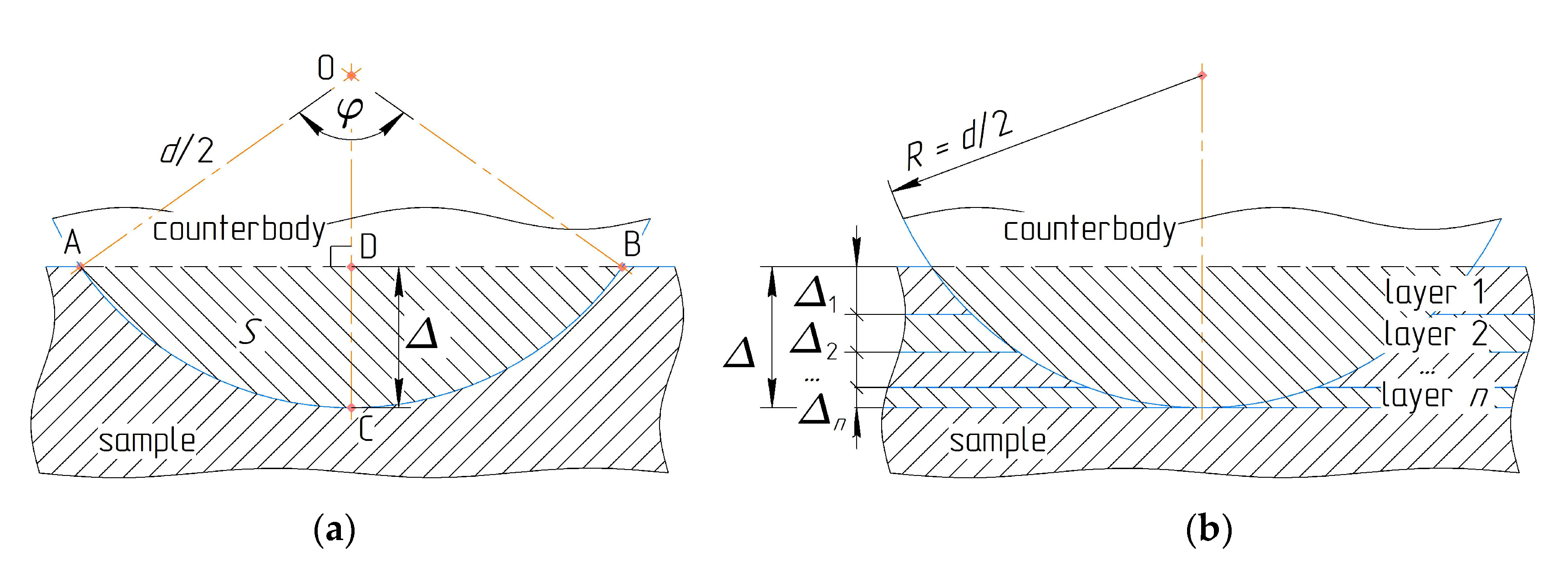
2.1. Mathematical Model
- zmax < Δs—partial wear of the layer(s) with the total depth of z = zmax = zp;
- zmax = Δs—full wear of all the layers with the total depth of z = zmax = Δs;
- zmax > Δs—wear of the sample with the total depth of z = zmax > Δs.
2.2. A Particular Case Study
2.3. Experimental Equipment
- –
- X-ray diffraction analysis is conducted by diffractometer “DRON UM-1” (“MTPK-LOMO” Ltd., Saint Petersburg, Russia) in Cu Kα1 radiation using graphite monocrystal monochromator on diffracted beam;
- –
- Metallographic analysis is carried out by microscopes “MIM-8” (“MTPK-LOMO” Ltd., Saint Petersburg, Russia) and “Neophot-21” (Carl Zeiss Jena GmbH, Oberkochen, Germany);
- –
- X-ray spectral analysis is realized using scanning electron microscope “JSM-6490LV” (Tokyo Boeki Ltd., Tokyo, Japan).
3. Results
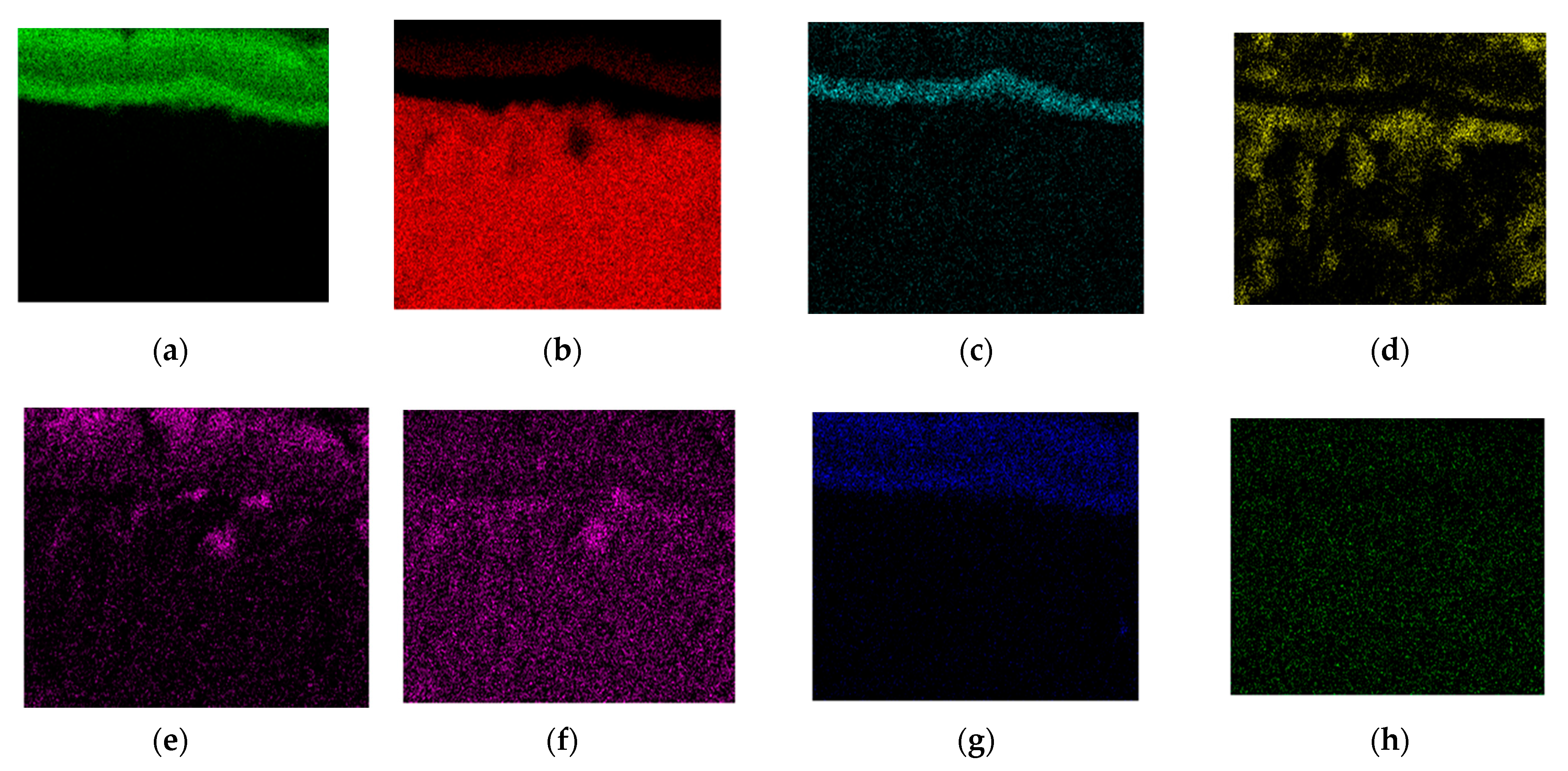
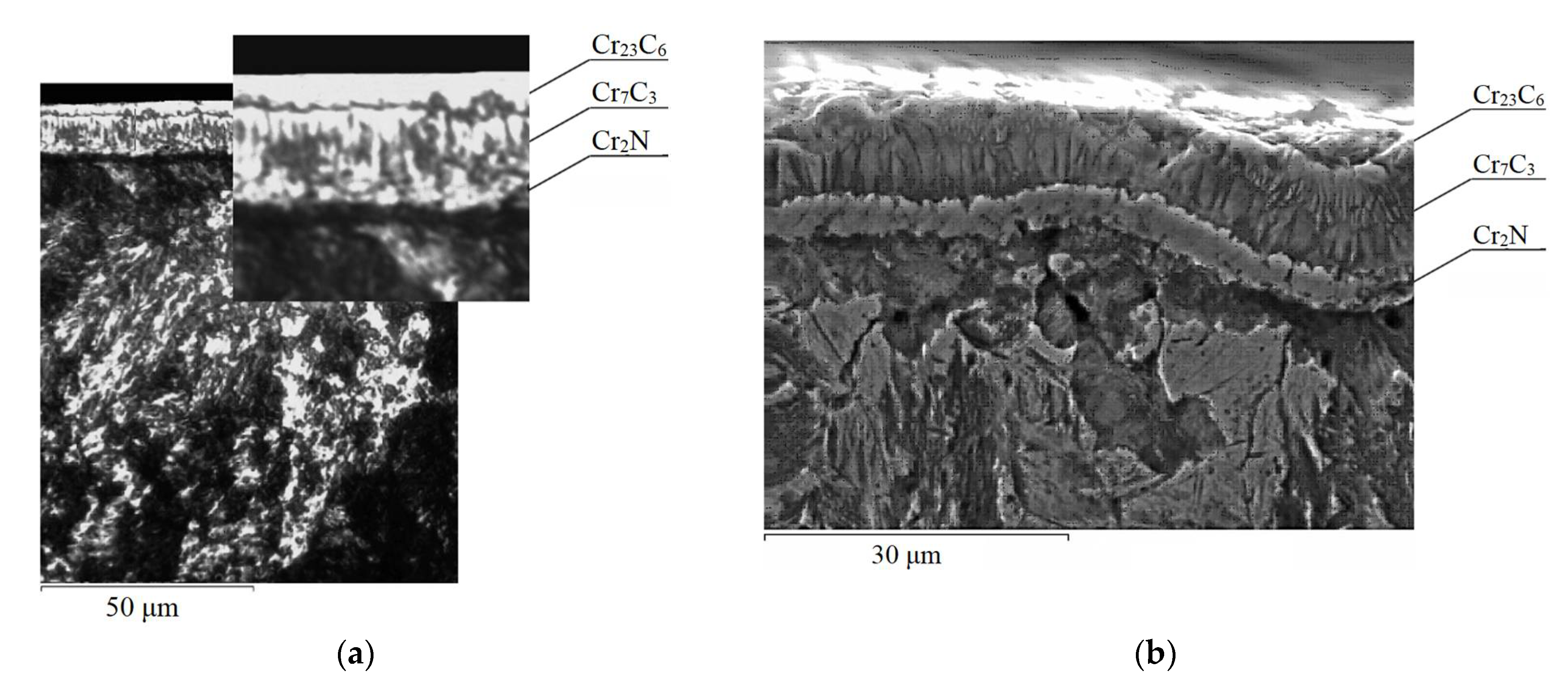
3.1. Microstructure of Coatings after Nitrogenchroming of Steels
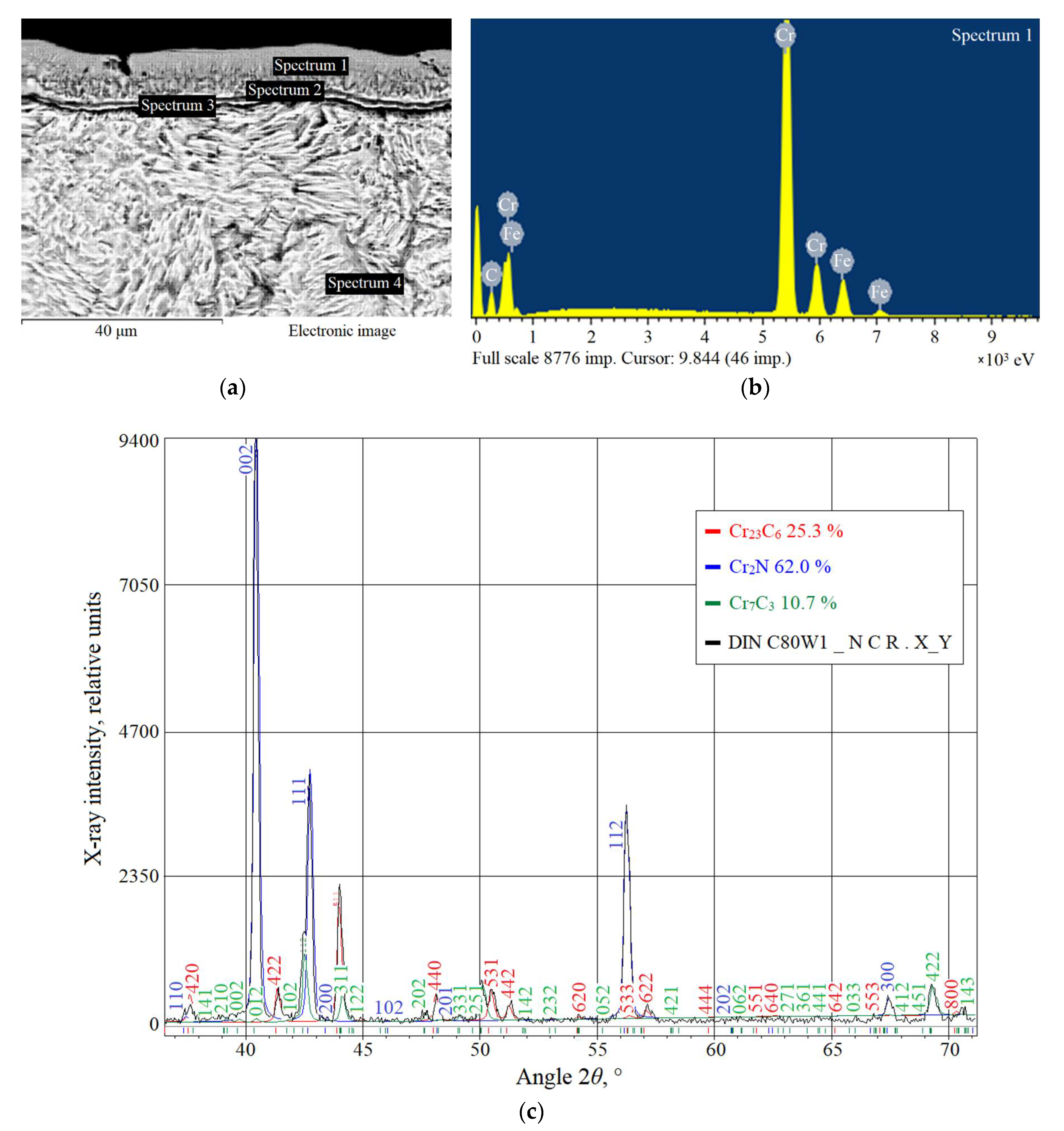
3.1.1. Steel DINC80W1
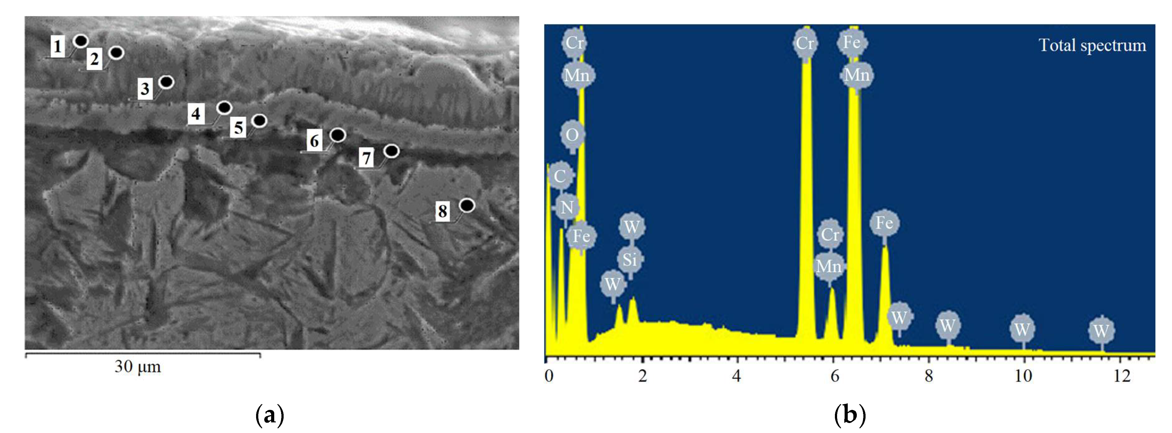
3.1.2. Steel DIN 105WCr6
3.1.3. Comparative Analysis of Coatings
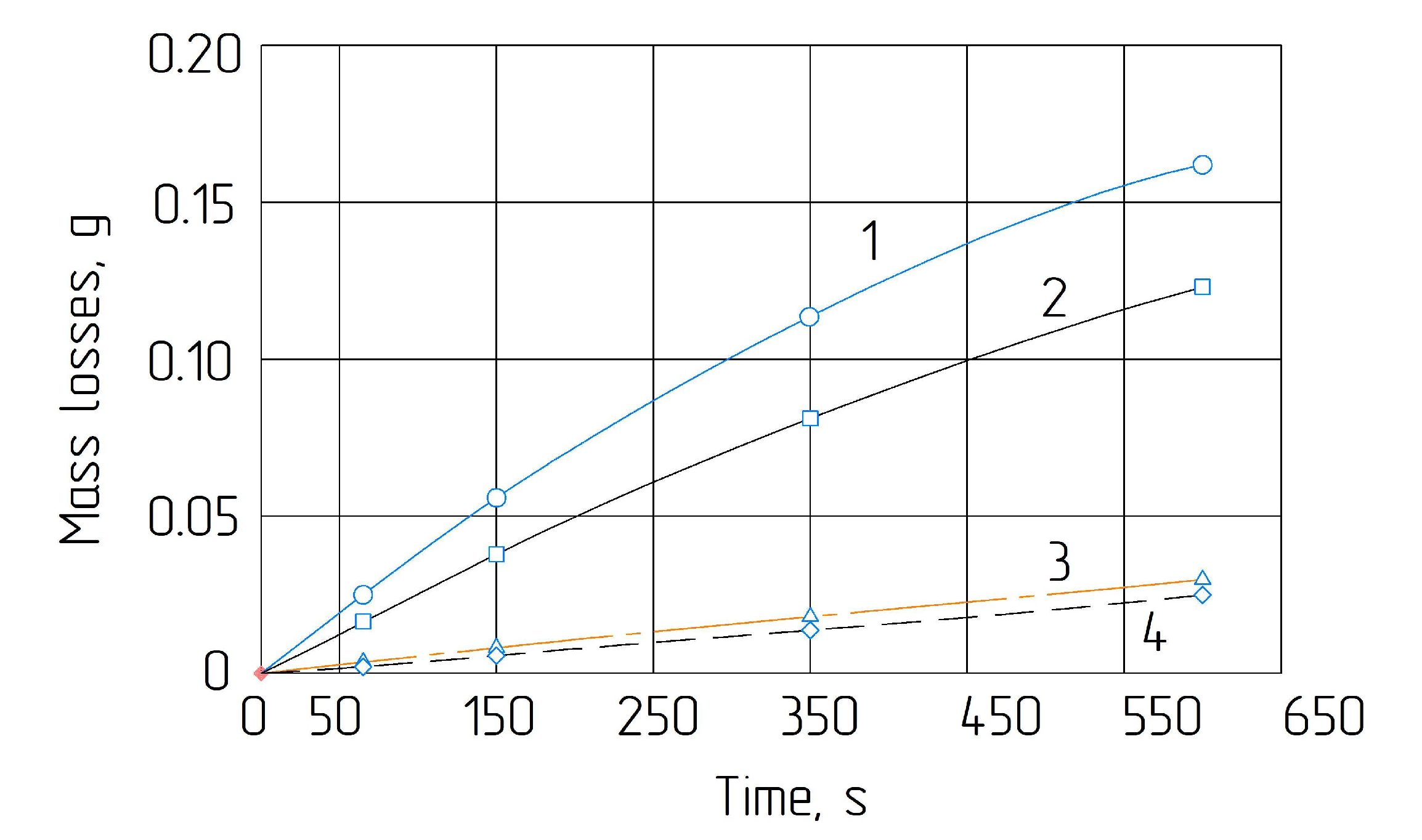
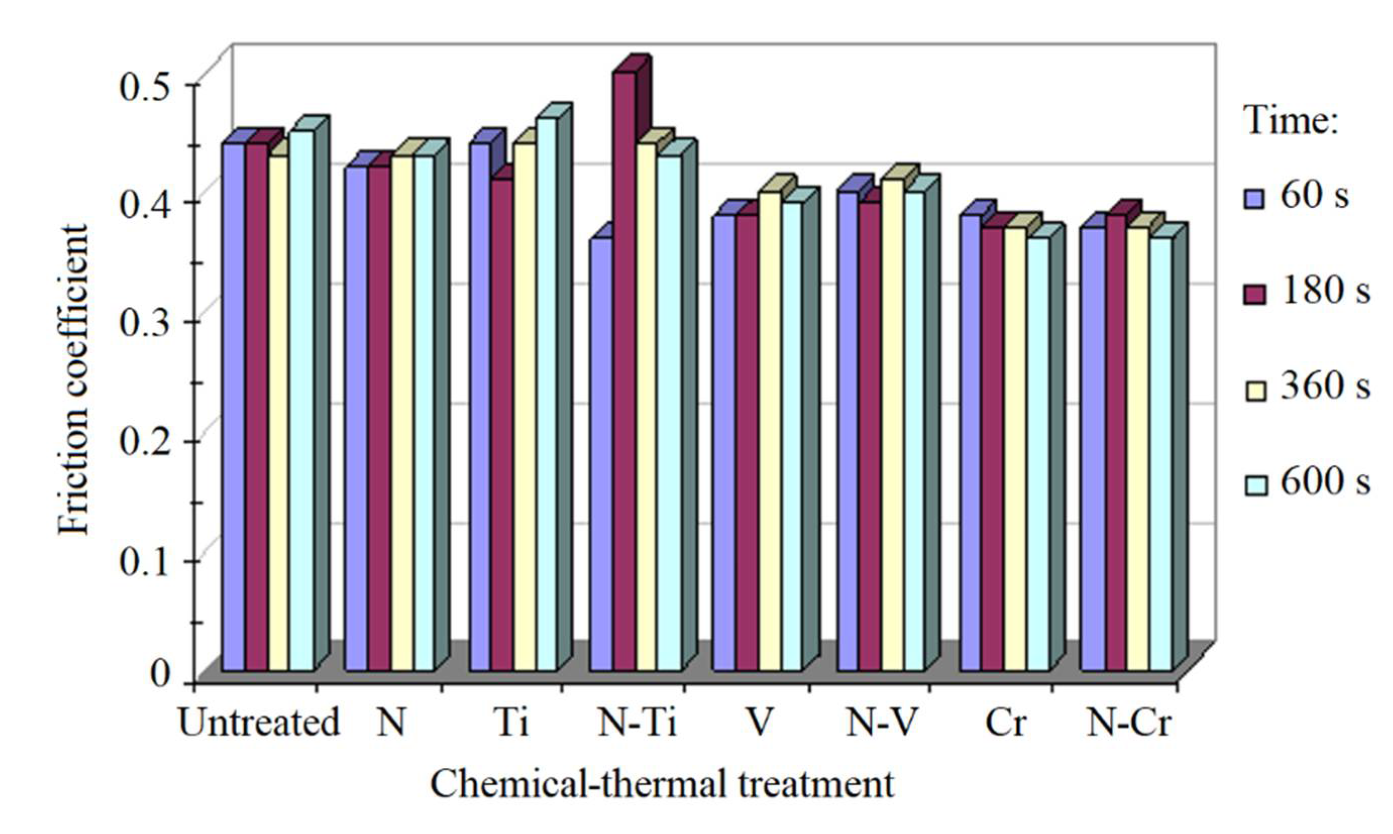
3.2. Wear Resistance of Steel DIN C80W1 after Chemical-Thermal Treatment
4. Discussion
5. Conclusions
Author Contributions
Funding
Institutional Review Board Statement
Informed Consent Statement
Data Availability Statement
Acknowledgments
Conflicts of Interest
References
- Pavlenko, I.; Saga, M.; Kuric, I.; Kotliar, A.; Basova, Y.; Trojanowska, J.; Ivanov, V. Parameter Identification of Cutting Forces in Crankshaft Grinding Using Artificial Neural Networks. Materials 2020, 13, 5357. [Google Scholar] [CrossRef] [PubMed]
- Krol, O.; Sokolov, V. Parametric Modeling of Gear Cutting Tools. In Proceedings of the International Scientific-Technical Conference Manufacturing, Poznan, Poland, 19–22 May 2019. [Google Scholar] [CrossRef]
- Zhou, W.; Lin, J.; Feng, F.; Ma, Y.; Zha, H.; Ji, W.; Jiang, E.; Cai, Z.; Feng, P. Performance improvement of carbide cutting tool for Ti6Al4V alloys using electromagnetic treatment. Int. J. Adv. Manuf. Technol. 2021, 113, 1547–1560. [Google Scholar] [CrossRef]
- Parfenov, V.D.; Basova, G.D. Surface coating metrology of carbides of cutting tools. IOP Conf. Ser. Earth Environ. Sci. 2017, 87, 82036. [Google Scholar] [CrossRef]
- Shvets, S.V.; Astakhov, V.P. Effect of Insert Angles on Cutting Tool Geometry. J. Eng. Sci. 2020, 7, A1–A6. [Google Scholar] [CrossRef]
- Gorlenko, A.O.; Davydov, S.V.; Shevtsov, M.Y.; Boldyrev, D.A. Wear-Resistance Increase of Friction Surfaces of Steel Machine Parts by Electro-Mechanical Hardening. Steel Transl. 2019, 49, 800–805. [Google Scholar] [CrossRef]
- Ye, H.; Le, F.; Wei, C.; Ye, K.; Liu, S.; Wang, G. Fatigue crack growth behavior of Ti-6Al-4V alloy fabricated via laser metal deposition: Effects of building orientation and heat treatment. J. Alloy. Compd. 2021, 868, 159023. [Google Scholar] [CrossRef]
- Storozhenko, M.; Umanskyi, O.; Tarelnyk, V.; Koval, O.; Gubin, Y.; Mikulina, M.; Martsenyuk, I.; Kostenko, O.; Kurinna, T. Structure and Wear Resistance of FeNiCrBSiC–MeB2 Electrospark Coatings. Powder Met. Met. Ceram. 2020, 59, 330–341. [Google Scholar] [CrossRef]
- Svirzhevskyi, K.; Zabolotnyi, O.; Tkachuk, A.; Zablotskyi, V.; Cagáňová, D. Methods of Evaluating the Wear Resistance of the Contact Surfaces of Rolling Bearings. In Proceedings of the Grabchenko’s International Conference on Advanced Manufacturing Processes, InterPartner 2020, Odessa, Ukraine, 8–11 September 2020. [Google Scholar] [CrossRef]
- Dhafer, W.A.-R.; Kostyk, V.; Glotka, A.; Chechel, M. The choice of the optimal temperature and time parameters of gas nitriding of steel. East. Eur. J. Enterp. Technol. 2016, 3, 44–50. [Google Scholar] [CrossRef] [Green Version]
- Development of alloy resistant in conditions of abrasive wear. Funct. Mater. 2021, 27, 170–177. [CrossRef]
- Pogrebnjak, A.; Sobol’, O.; Beresnev, V.; Turbin, P.; Kirik, G.; Makhmudov, N.; Il’Yashenko, M.; Shypylenko, A.; Kaverin, M.; Tashmetov, M.; et al. Phase Composition, Thermal Stability, Physical and Mechanical Properties of Superhard on Base Zr-Ti-Si-N Nanocomposite Coatings. Ceram. Eng. Sci. Proc. 2010, 31, 127–138. [Google Scholar] [CrossRef]
- Murčinková, Z.; Baron, P.; Tiňo, L.; Pollák, M.; Murčinko, J. Research and analysis of stress distribution in multilayers of coated tools. Int. J. Mater. Res. 2017, 108, 495–506. [Google Scholar] [CrossRef]
- Lehocka, D.; Klich, J.; Botkova, D.; Simkulet, V.; Foldyna, J.; Krejci, L.; Storkan, Z.; Kepic, J.; Hatala, M. Comparison of ultrasonically enhanced pulsating water jet erosion efficiency on mechanical surface treatment on the surface of aluminum alloy and stainless steel. Int. J. Adv. Manuf. Technol. 2019, 103, 1647–1656. [Google Scholar] [CrossRef]
- Kharlamov, Y.; Sokolov, V.; Krol, O.; Romanchenko, O. Research of the Influence of Conditions of D-gun Spraying on Properties of Tungsten and Chromium Carbides Coatings. In Proceedings of the Grabchenko’s International Conference on Advanced Manufacturing Processes, InterPartner 2020, Odessa, Ukraine, 8–11 September 2020. [Google Scholar] [CrossRef]
- Kulesh, Е.А.; Piliptsou, D.G.; Rogachev, A.V.; Hong, J.X.; Fedosenko, N.N.; Kolesnyk, V. Boron-Carbon Coatings: Structure, Morphology, and Mechanical Properties. J. Eng. Sci. 2020, 7, C1–C9. [Google Scholar] [CrossRef]
- Tarelnyk, V.; Gaponova, O.; Myslyvchenko, O.; Sarzhanov, B. Electrospark Deposition of Multilayer Coatings. Powder Met. Met. Ceram. 2020, 59, 76–88. [Google Scholar] [CrossRef]
- Tarelnyk, V.B.; Gaponova, O.P.; Konoplianchenko, Y.V.; Martsynkovskyy, V.S.; Tarelnyk, N.V.; Vasylenko, O.O. Improvement of Quality of the Surface Electroerosive Alloyed Layers by the Combined Coatings and the Surface Plastic Deformation. I. Features of Formation of the Combined Electroerosive Coatings on Special Steels and Alloys. Met. I Noveishie Tekhnologii 2019, 41, 47–69. [Google Scholar] [CrossRef] [Green Version]
- Sychuk, V.; Zabolotnyi, O.; Somov, D. Technology of Effective Abrasive Jet Machining of Parts Surfaces. In Proceedings of the International Conference on Design, Simulation, Manufacturing: The Innovation Exchange, DSMIE 2018, Sumy, Ukraine, 11–14 June 2018. [Google Scholar] [CrossRef]
- Кoстик, К.О. Development of the high-speed boriding technology of alloy steel. East. Eur. J. Enterp. Technol. 2015, 6, 8–15. [Google Scholar] [CrossRef] [Green Version]
- Kharlamov, O.Y.; Sokolov, I.V.; Krol, O.S.; Romanchenko, O.V. Analysis of physical and chemical transformations during thermal spraying of coatings based on carbides of tungsten and chromium. IOP Conf. Ser. Mater. Sci. Eng. 2020, 985, 12036. [Google Scholar] [CrossRef]
- Physical-mechanical properties and structural-phase state of nanostructured wear-resistant coatings based on nitrides of refractory metals Ti and Zr. Funct. Mater. 2019, 26, 548–555. [CrossRef]
- Knapčíková, L.; Dupláková, D.; Radchenko, S.; Hatala, M. Rheological behavior modelling of composite materials used in engineering industry. TEM J. 2017, 6, 242–245. [Google Scholar] [CrossRef]
- Doeva, O.; Masjedi, P.K.; Weaver, P.M. A semi-analytical approach based on the variational iteration method for static analysis of composite beams. Compos. Struct. 2021, 257, 113110. [Google Scholar] [CrossRef]
- Yukhymenko, L.M.; Pavlenko, I.; Pitel, J.; Mizakova, J.; Ostroha, R.; Bocko, J. Ensuring the Reliability of Pneumatic Classification Process for Granular Material in a Rhomb-Shaped Apparatus. Appl. Sci. 2019, 9, 1604. [Google Scholar] [CrossRef] [Green Version]
- Zefirov, N.S.; Kulov, N.N. Chemical Encyclopedia; Great Russian Encyclopedia: Moscow, Rusia, 1998. [Google Scholar]
- Kurylo, N.A.; Khyzhnyak, V.G.; Sigova, V.I. Ultrafine Diffusion Carbonitride Coatings on Steels and Hard Alloys: Monograph; Sumy Regional Institute of Postgraduate Education: Sumy, Ukraine, 2011. [Google Scholar]
- Inoue, S.; Uchida, H.; Hioki, A.; Koterazawa, K.; Howson, R.P. Structure and composition of (Ti, Al)N films prepared by r.f. planar magnetron sputtering using a composite target. Thin Solid Films 1995, 271, 15–18. [Google Scholar] [CrossRef]
- Kaporin, V.A. Improvement of the Technology for Restoration of Shafts in Agricultural Machinery during Dimensional Pro-cessing of Microporous Coatings on an Iron Base. Ph.D. Thesis, Polzunov Altai State Technical University, Novosibirsk, Rusia, 2020. [Google Scholar]
- Korobov, Y.S.; Filippov, M.A.; Makarov, A.V.; Verkhorubov, V.S.; Nevezhin, S.V.; Kashfullin, S.V. Resistance of deposited layers and sprayed coatings with a metastable austenite structure against abrasive and adhesive wear. Izv. Samara Sci. Cent. Russ. Acad. Sci. 2015, 17, 224–230. [Google Scholar]
- Hignjak, V.G.; Calashnicov, G.Y.; Harchenko, N.A.; Hovorun, Т.P.; Hignjak, О.V.; Dolgikh, V.Y.; Holyshevskiy, O.O. The structure, composition and properties of nitrided alloys after diffusion metallization. J. Nano Electron. Phys. 2015, 7, 04033-1–04033-6. [Google Scholar]
- Moiseev, A.V. Calculation Methods for Determining the Physicochemical Properties of Hydrocarbon Systems, Oils and Pe-troleum Products: Examples and Tasks; Komsomolsk-on-Amur State Technical University: Komsomolsk-on-Amur, Russia, 2010. [Google Scholar]
- Ma, Y.-D.; Guo, M.-Y.; Li, W.; Yang, Y.; Gao, P.-Y.; Cui, Y.-H.; Sun, W.-W.; Wang, Y.-W.; Wang, L.; Dong, Y.-C. Microstructure and properties of Cr7C3-CrSi2 composite coatings prepared by plasma spraying. Surf. Coat. Technol. 2021, 412, 127011. [Google Scholar] [CrossRef]
- Qi, Z.; Liu, B.; Wu, Z.; Zhu, F.; Wang, Z.; Wu, C. A comparative study of the oxidation behavior of Cr2N and CrN coatings. Thin Solid Films 2013, 544, 515–520. [Google Scholar] [CrossRef]
- Lakhtin, Y.M.; Kogan, Y.D. Steel Nitriding; Mashinostroyeniye: Moscow, Russia, 1976. [Google Scholar]
- Fossati, A.; Borgioli, F.; Galvanetto, E.; Bacci, T. Glow-discharge nitriding of AISI 316L austenitic stainless steel: Influence of treatment time. Surf. Coat. Technol. 2006, 200, 3511–3517. [Google Scholar] [CrossRef]
- Belov, N. State Diagrams of Ternary and Quaternary Systems; MISIS National University of Science and Technology: Moscow, Russia, 2007. [Google Scholar]
- Huang, C.-H.; Luo, R.; Zeng, J.; Song, C.-Y. Effect of system parameters on tread-hollow wear of high-speed train wheels. J. Traffic Transp. Eng. 2016, 16, 55–62. [Google Scholar]
- Luoma, R. A Thermodynamic Analysis of the System Fe-Cr-Ni-C-O; Acta Polytechnica Scandinavica, Chemical Technology Series; Finnish Academies of Technology: Helsinki, Finland, 2002. [Google Scholar]
- Toth, L. Transition Metal. Carbides and Nitrides; Academic Press: New York, NY, USA, 1971. [Google Scholar]
- Burkin, V.V.; Tabachenko, A.N.; Afanas’Eva, S.A.; Ishchenko, A.N.; Sammel’, A.Y.; Skosyrskii, A.B.; Chupashev, A.V. Synthesis of Two-Layer Metal–Ceramic Materials with High-Velocity-Impact Resistance Based on Refractory Compounds and Titanium. Tech. Phys. Lett. 2018, 44, 344–347. [Google Scholar] [CrossRef]
- Młynarczak, A.; Jozwiak, K.; Mesmacque, G. Wear Resistance of Multiphase Diffusion Carbide Coatings. Adv. Eng. Mater. 2003, 5, 789–793. [Google Scholar] [CrossRef]
- Zhu, R.; Mi, X. Aging problem and counter method for 1Cr25Ni20Si2 steel nitriding tank. Heat Treat. Met. 2020, 45, 228–230. [Google Scholar] [CrossRef]
- Kurny, A.; Mallya, R.; Rao, M. On the formation of austenite during ion nitriding of armco iron. J. Less Common Met. 1988, 144, 201–207. [Google Scholar] [CrossRef]
- Kostyk, K.; Hatala, M.; Kostyk, V.; Ivanov, V.; Pavlenko, I.; Duplakova, D. Simulation of Diffusion Processes in Chemical and Thermal Processing of Machine Parts. Processes 2021, 9, 698. [Google Scholar] [CrossRef]
- Myshkin, N.K.; Petrokovets, M.I.; Kovalev, A.V. Tribology of polymers: Adhesion, friction, wear, and mass-transfer. Tribol. Int. 2005, 38, 910–921. [Google Scholar] [CrossRef]
- Cai, Y.; Zhu, L.; Cui, Y.; Shan, M.; Li, H.; Xin, Y.; Han, J. Fracture and wear mechanisms of FeMnCrNiCo + x(TiC) composite high-entropy alloy cladding layers. Appl. Surf. Sci. 2021, 543, 148794. [Google Scholar] [CrossRef]
- Kolesnyk, V.; Peterka, J.; Kuruc, M.; Šimna, V.; Moravčíková, J.; Vopát, T.; Lisovenko, D. Experimental Study of Drilling Temperature, Geometrical Errors and Thermal Expansion of Drill on Hole Accuracy When Drilling CFRP/Ti Alloy Stacks. Materials 2020, 13, 3232. [Google Scholar] [CrossRef] [PubMed]
- Volosova, M.; Vereschaka, A.; Andreev, N.; Sotova, C.; Bublikov, J. Improvement of the performance properties of cutting tools using the multilayer composite wear-resistant coatings based on nitrides of Cr, Mo, Zr, Nb, and Al. Mater. Today 2021, 38, 1421–1427. [Google Scholar] [CrossRef]
- Zaulychny, Y.V.; Hignjak, V.G.; Harchenko, N.A.; Hovorun, T.P.; Hignjak, O.V.; Dolgikh, V.Y. Influence of Interatomic Interaction Processes on the Mechanical Properties of Carbide Coatings Based on Ti, V and Cr, Obtained by Diffusion Metallization. J. Nano Electron. Phys. 2016, 8, 4008. [Google Scholar] [CrossRef]
- Kim, Y.S.; Park, H.J.; Lim, K.S.; Hong, S.H.; Kim, K.B. Structural and Mechanical Properties of AlCoCrNi High Entropy Nitride Films: Influence of Process Pressure. Coatings 2019, 10, 10. [Google Scholar] [CrossRef] [Green Version]


| Layer Number | Density kg/m3 | Thickness, μm | Microhardness, GPa | Phase Composition |
|---|---|---|---|---|
| Multilayer Coating | ||||
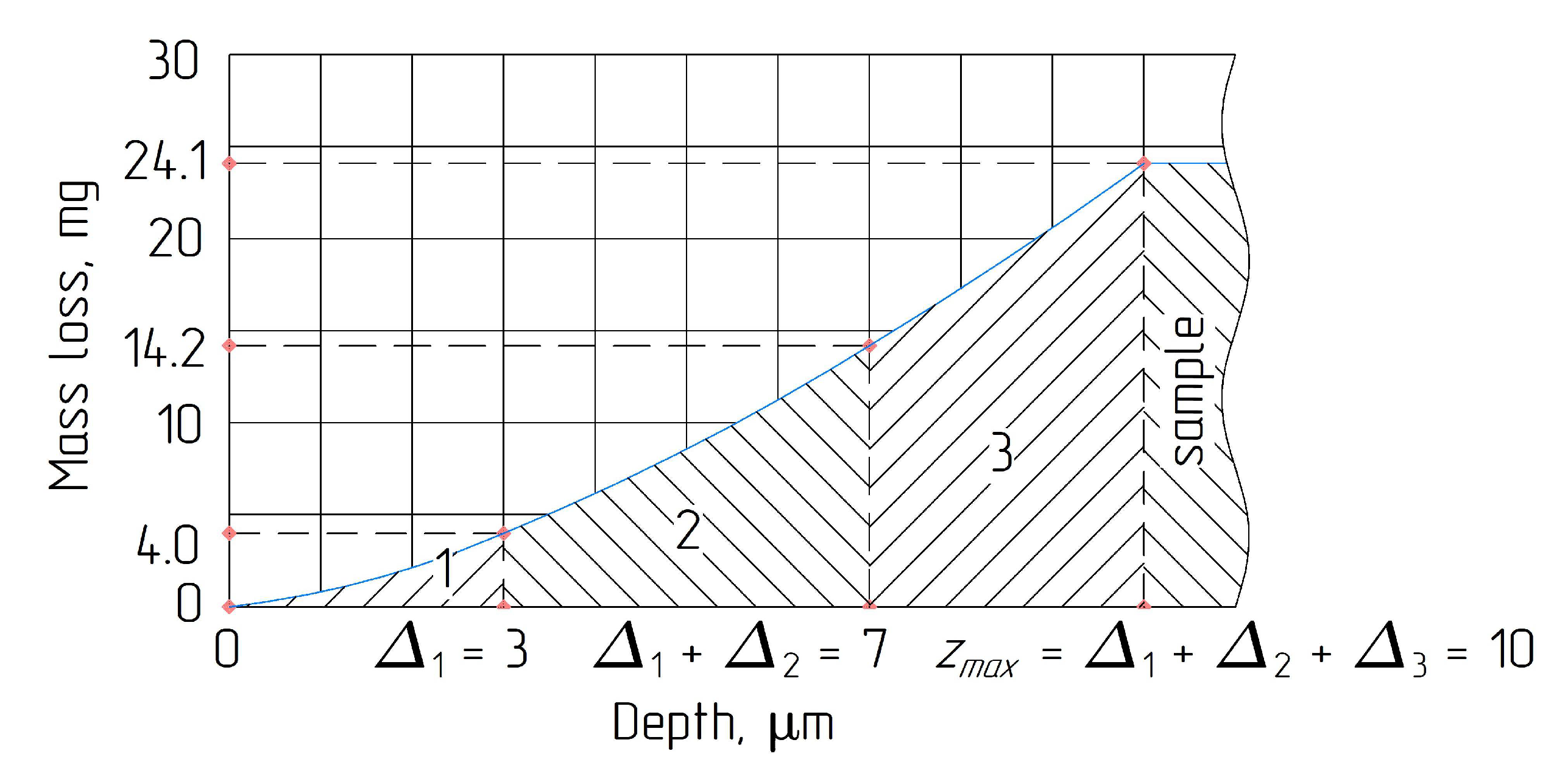
| 1 | 7000 | 3 | 18.2 | Cr23C6 |
| 2 | 6970 | 4 | 16.2 | Cr7C3 |
| n = 3 | 6800 | 3 | 8.8 | Cr2N |
| Sample | ||||
| n + 1 = 4 | 7840 | – | – | – |
| Wearing Till Layer No. | The Total Mass Losses, mg | |
|---|---|---|
| min, ms(zj–1) | max, ms(zj) | |
| 1 | – | 4.0 |
| 2 | 4.0 | 14.2 |
| 3 | 14.2 | 24.1 |
| 4 | 24.1 | 24.1 |
| Spectrum No. | Distance from the Surface μm | Content of Elements, % Mass | ||||
|---|---|---|---|---|---|---|
| C | Cr | Fe | Si | Mn | ||
| 1 | 3.0 | 5.4 | 84.6 | 10.0 | – | – |
| 2 | 7.0 | 9.0 | 79.8 | 11.2 | – | – |
| 3 | 10.0 | 9.1 | 78.6 | 12.1 | 0.2 | – |
| 4 | 50.0 | 0.7 | 1.5 | 95.9 | 1.5 | 0.4 |
| Scheme | Distance from the Surface, μm | Content of Elements,% Mass | |||||||
|---|---|---|---|---|---|---|---|---|---|
| C | N | Cr | Fe | O | Si | Mn | W | ||
| 1 | 2.0 | 5.4 | – | 92.2 | 2.4 | – | – | – | – |
| 2 | 4.0 | 5.6 | – | 91.8 | 2.5 | – | – | – | 0.1 |
| 3 | 10.0 | 8.9 | 0.3 | 82.2 | 2.7 | 0.8 | – | – | 0.1 |
| 4 | 11.0 | 1.2 | 9.2 | 86.4 | 2.9 | 1.1 | 0.2 | – | – |
| 5 | 12.0 | 1.2 | 9.4 | 81.8 | 3.8 | 3.3 | 0.5 | – | – |
| 6 | 14.0 | 1.0 | – | 7.9 | 89.6 | – | 0.6 | 0.4 | 0.5 |
| 7 | 17.0 | 1.0 | – | 7.8 | 89.4 | – | 0.9 | 0.4 | 0.5 |
| 8 | 22.0 | 1.0 | – | 3.3 | 94.2 | – | – | 0.8 | 0.7 |
Publisher’s Note: MDPI stays neutral with regard to jurisdictional claims in published maps and institutional affiliations. |
© 2021 by the authors. Licensee MDPI, Basel, Switzerland. This article is an open access article distributed under the terms and conditions of the Creative Commons Attribution (CC BY) license (https://creativecommons.org/licenses/by/4.0/).
Share and Cite
Pavlenko, I.; Zajac, J.; Kharchenko, N.; Duplák, J.; Ivanov, V.; Kostyk, K. Estimation of Wear Resistance for Multilayer Coatings Obtained by Nitrogenchroming. Metals 2021, 11, 1153. https://doi.org/10.3390/met11081153
Pavlenko I, Zajac J, Kharchenko N, Duplák J, Ivanov V, Kostyk K. Estimation of Wear Resistance for Multilayer Coatings Obtained by Nitrogenchroming. Metals. 2021; 11(8):1153. https://doi.org/10.3390/met11081153
Chicago/Turabian StylePavlenko, Ivan, Jozef Zajac, Nadiia Kharchenko, Ján Duplák, Vitalii Ivanov, and Kateryna Kostyk. 2021. "Estimation of Wear Resistance for Multilayer Coatings Obtained by Nitrogenchroming" Metals 11, no. 8: 1153. https://doi.org/10.3390/met11081153