Article

In Situ Synthesis of Core-Shell-Structured SiCp Reinforcements in Aluminium Matrix Composites by Powder Metallurgy

1
School of Materials Science and Engineering, Xi’an University of Technology, No. 5 Jinhua South Road, Xi’an 710048, China
2
Shandong Province Key Laboratory of Powder Metallurgy in Advanced Manufacturing, Laiwu Vocational and Technical College, No.1 Shancai Street, Laiwu 271100, China
*
Author to whom correspondence should be addressed.
Metals 2021, 11(8), 1201; https://doi.org/10.3390/met11081201
Submission received: 26 May 2021 / Revised: 21 July 2021 / Accepted: 25 July 2021 / Published: 28 July 2021
(This article belongs to the Special Issue New Trend in Metal-Ceramic Composite Materials)

Abstract

:
SiCp reinforced aluminium matrix composites (AMCs), which are widely used in the aerospace, automotive, and electronic packaging fields along with others, are usually prepared by ex situ techniques. However, interfacial contamination and poor wettability of the ex situ techniques make further improvement in their comprehensive performance difficult. In this paper, SiCp reinforced AMCs with theoretical volume fractions of 15%, 20%, and 30% are prepared by powder metallurgy and in situ reaction via an Al-Si-C system. Moreover, a combined method of external addition and an in situ method is used to investigate the synergistic effect of ex situ and in situ SiCp on AMCs. SiC particles can be formed by an indirect reaction: 4Al + 3C → Al4C3 and Al4C3 + 3Si → 3SiC + 4Al. This reaction is mainly through the diffusion of Si, in which Si diffuses around Al4C3 and then reacts with Al4C3 to form SiCp. The in situ SiC particles have a smooth boundary, and the particle size is approximately 1–3 μm. A core-shell structure having good bonding with an aluminium matrix was generated, which consists of an ex situ SiC core and an in situ SiC shell with a thickness of 1–5 μm. The yield strength and ultimate tensile strength of in situ SiCp reinforced AMCs can be significantly increased with a constant ductility by adding 5% ex situ SiCp for Al-28Si-7C. The graphite particle size has a significant effect on the properties of the alloy. A criterion to determine whether Al4C3 is a complete reaction is achieved, and the forming mechanism of the core-shell structure is analysed.

1. Introduction

Aluminium matrix composites (AMCs) are attractive materials for lightweight applications owing to their high strength-to-density ratio, good wear and fatigue resistance, and high-temperature mechanical properties. In particular, particulate-reinforced AMCs have been increasingly studied [1,2]. SiC particles (SiCp) have been identified as probably the most competitive and effective discontinuous reinforcement for Al and Al alloy matrices due to their high melting point, high stiffness, good thermal stability, good chemical resistance, and low coefficient of thermal expansion [3]. Almost all existing methods for preparing SiCp-reinforced AMCs use ex situ techniques, such as rheocasting [4], infiltration [5], melt-stirring [6], and powder metallurgy techniques [7,8]. Chen Z. Z. et al. produced SiCp-reinforced 2024 aluminium-matrix composites by powder metallurgy and studied their fatigue crack initiation and small crack growth behaviours [9]. Yang Y. et al. fabricated SiCp-reinforced A356 aluminium matrix composites by the ultrasonic dispersion of nano-sized SiCp in a molten aluminium alloy and found that the mechanical properties significantly improved even at a low weight fraction of nano-sized SiCp [10]. Hu Q. Y. et al. fabricated A356-SiC and 6061-SiC composites by a vacuum-assisted high-pressure die casting (HPDC) process [11]. Additionally, extensive studies have been conducted on the Al-SiC interfacial structure and the effect of various preparation methods on interfacial reactions [12,13]. The Al-SiC interface between the reinforcement and matrix can effectively transfer load from the matrix to the reinforcement, which plays a crucial role in the deformation and service of SiCp-reinforced AMCs.
However, the disadvantage of ex situ techniques, such as interfacial contamination and poor wettability between ex-SiCp and the matrix, limits their application in aerospace and other advanced fields [14]. During the past decades, considerable research efforts have been made towards in situ fabrication, which is devoted to reducing incompatibility and interfacial pollution [15]. In addition, in situ synthesised reinforcements can obtain better thermodynamic stability, finer size, and a more uniform distribution compared to ex situ particles [16]. Thus, AMCs reinforced by in situ SiCp are expected to exhibit superior mechanical properties compared to those produced by conventional processes [11].
The in situ synthesis of SiCp has been studied by many scholars. Sha J. J. et al. synthesised in situ SiC by the reaction 2ZrSi2 + B4C + 3C = 2ZrB2 + 4SiC, and the mean sizes of ZrB2 and SiCp were approximately 300 and 40 nm, respectively [17]. Ren R. et al. prepared SiC nanowhiskers from photovoltaic silicon waste, quartz sand, and coconut fibre, which is a novel, clean, and sustainable method of preparing SiC nanowhiskers [18]. Gustafsson et al. fabricated Al2O3/SiC nanocomposites by a new technique involving the in situ synthesis of nano-sized SiCp, which contains two reactions: SiO2(s,l) + C(s) → SiO(g) + CO(g) and SiO(g) + 2C(s) → SiC(s) + CO(g). The SiC particle size was significantly reduced compared to the Al2O3/SiC microstructures fabricated through conventional powder processing [19]. Du X. F. et al. performed some research on in situ SiCp formation in an Al matrix [20,21]. They designed a liquid-solid reaction to realise the in situ synthesis of SiCp in an Al melt and prepared SiCp-reinforced Al-18Si alloys by applying the casting method. Then, multi-scale SiCp-reinforced AMCs were prepared by powder metallurgy. EI Oualid Mokhnache et al. synthesised Al2O3 and SiC in situ from an Al-SiO2-C system by reaction hot pressing, and the change in the Al4C3 phase and its effect on the properties were discussed [22]. Al4C3 is a brittle phase and leads to hydrolysis, which should be inhibited in AMCs. The effect of the Si content on Al4C3 transformation still needs quantitative investigation, and the critical conditions for the complete reaction of Al4C3 cannot be found if the content changes in Al-Si-C systems [23].
To make full use of their advantages, ex situ and in situ SiCp co-reinforced AMCs were prepared in this study. Furthermore, in situ SiCp-reinforced AMCs were synthesised for comparison. Based on the phase diagram, the composition of the Al-Si-C system was designed to determine the process conditions for AMCs with in situ SiCp reinforcement without Al4C3. The effects of ex situ SiCp and in situ SiC on the evolution of the microstructure and mechanical properties were studied.

2. Experimental Procedure

2.1. Materials and Processes

Commercial pure Al powder (99.0 wt% purity, diameter ~30 μm), Si powder (99.0 wt% purity, diameter ~30 μm), graphite powder (99.0 wt% purity), and polyangular SiC ceramic powder (98.5 wt% purity, diameter ~40 μm) were used in this study. To investigate the effect of graphite powder particle size on the properties, two sizes were applied; the average particles sizes were 6.5 and 10 μm, labelled G1 and G2, respectively. The fabrication processes of in situ SiCp reinforced AMCs mainly consisted of four steps. The first step was to mix the three powders for 4 h in an ethanol solution by planetary ball milling (PBM, PM-100, Retsch, Haan, Germany) at a rotation speed of 200 rpm and a ball-to-powder weight ratio of 3:1, and then the powder mixture was dried. The theoretically calculated volume fractions of in situ SiCp in the AMCs were 15, 20, and 30 vol%. Then, the powder mixture was compacted at room temperature in a 12.7 mm diameter die at a maximum pressure of 1500 MPa. The third step was sintering in a tube furnace for 2 h at 1000 °C with a heating rate of 10 °C/min in an argon gas atmosphere. The sintered billets were subsequently re-sintered by spark plasma sintering (SPS, LABOX-330, Sinter Land, Niigata, Japan) at 570 °C at a pressure of 30 MPa for 30 min under vacuum conditions. During sintering, the following reactions may occur in Al-Si-C system:
4Al + 3C → Al4C3
4Al + 3SiC → Al4C3 + 3Si
Al4C3 + 3Si → 3SiC + 4Al
Si + C → SiC
Therefore, in this study, in-situ SiCp can be synthesised by indirect reactions via Equations (1) and (3) [24].
To prepare AMCs reinforced by ex situ and in situ SiCp, the mixed powder contained Al, Si, C, and acid pickled SiC in the first step. The difference between preparing in-situ SiCp reinforced AMCs lies in the treatment of powders and the first step; other steps were done under the same aforementioned conditions. The SiC particles were acid pickled by a mixed acid (HNO3:HF = 3:2, vol%), 100 millilitres of mixed acid could pickle ten grams of silicon carbide, the concentration of HNO3 and HF was diluted to a concentration of 10%. By pickling, the silicon atoms of the surface layer of SiC can be reacted away, exposing the carbon atoms. The reaction is as follows [25]:
4HNO3 + Si → SiO2 + 4NO2 + 2H2O
SiO2 + 6HF → H2SiF6 + 2H2O
The acid pickled SiC particles were washed with distilled water until the pH value of the cleaning solution was neutral, then dried in the drying oven. The mass fraction of the ex situ SiCp accounted for 5%. The AMC samples prepared are shown in Table 1.

2.2. Characterisation

The sintered samples were characterised by X-ray diffraction (XRD-7000, SHIMADZU, Kyoto, Japan) with a Cu Ka radiation source to identify the phases. The microstructure evolution of the composites and morphology of in situ synthesised SiC particles were observed by optical microscopy (OM-GX71, OLYMPUS, Tokyo, Japan) and field-emission scanning electron microscopy (FESEM, JSM-6700F, JEOL, Tokyo, Japan). The tensile properties of the samples were tested by a universal tensile testing machine (HT-2402, HUANG HE, Changchun, China).

3. Results

3.1. Microstructure

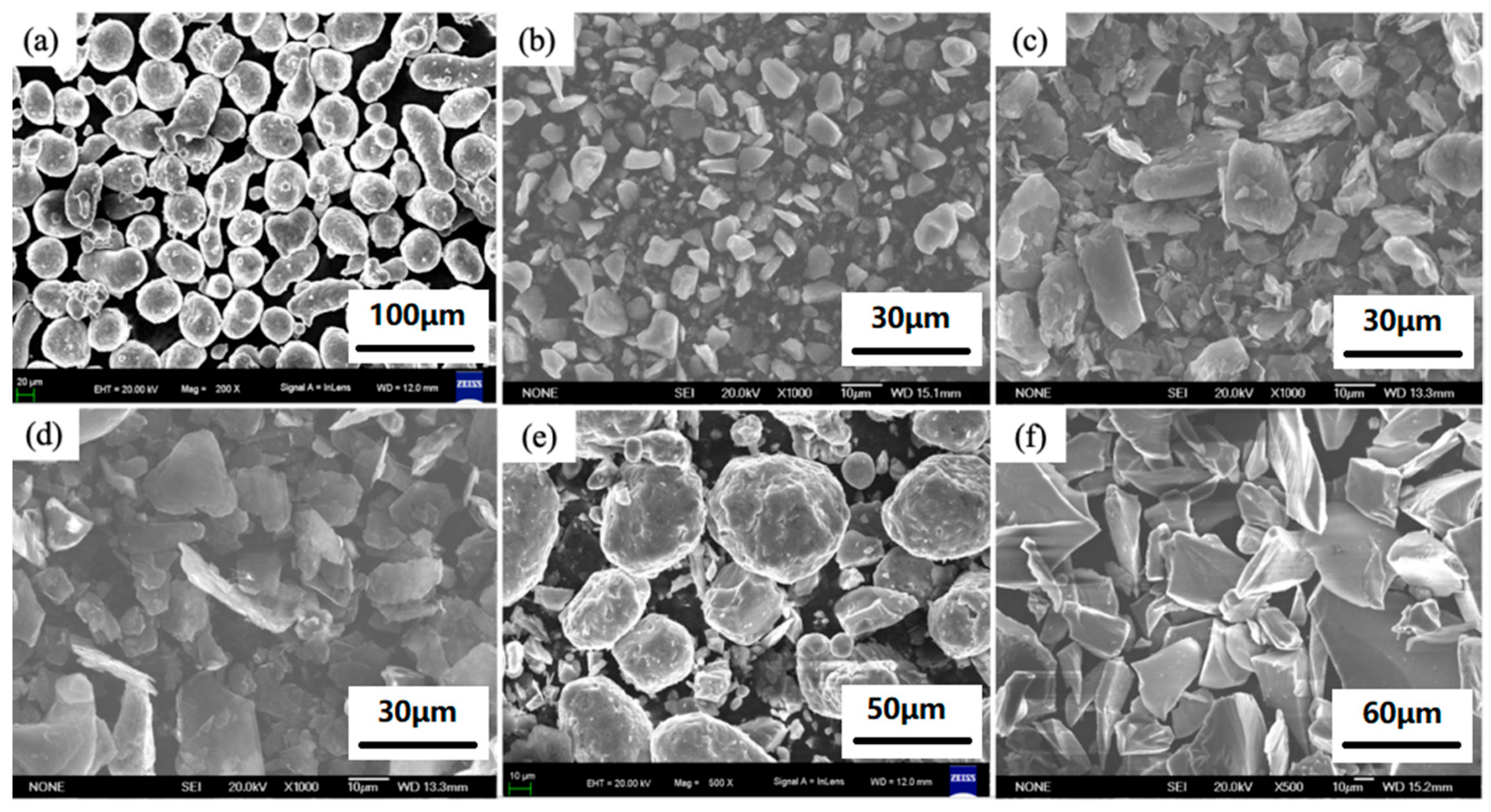
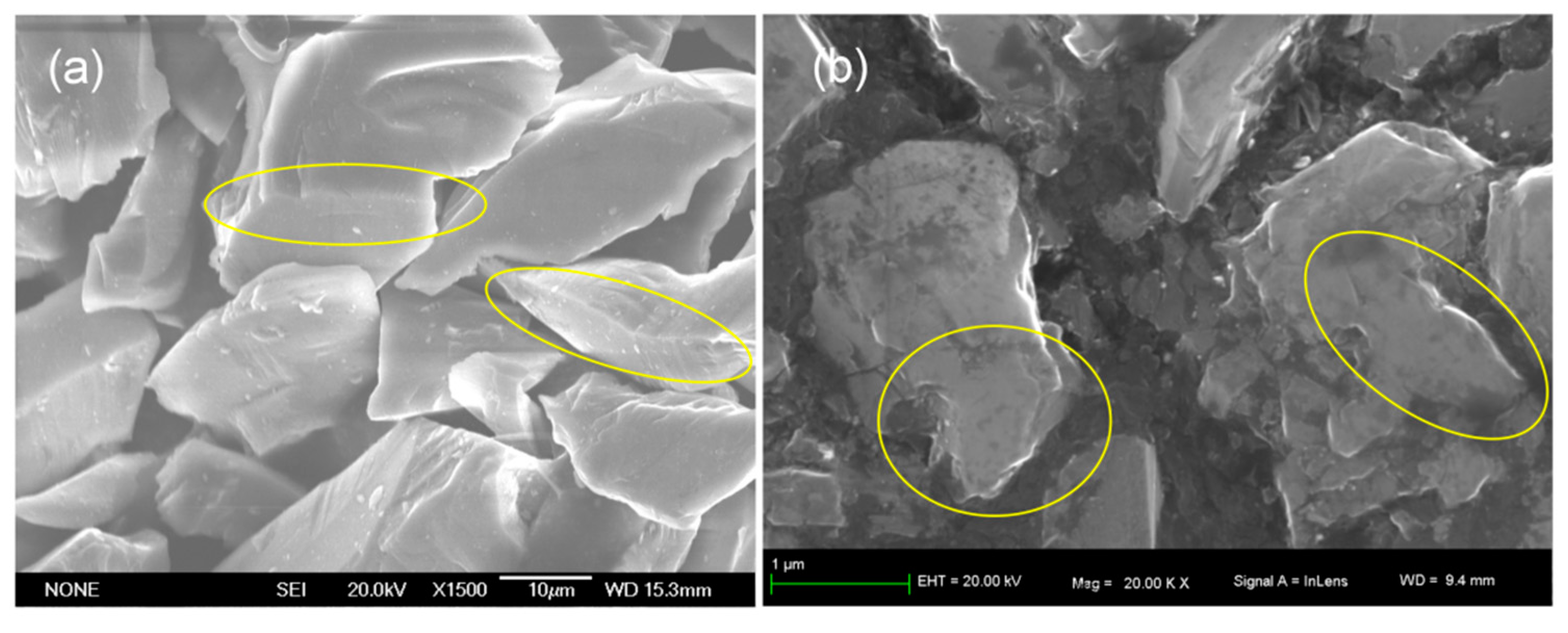
3.1.1. Morphologies of the Powders

SEM micrographs of the raw materials and premixed powder are shown in Figure 1. The Al particles were nearly spherical, as shown in Figure 1a, and the Si particles were irregular polygons, as shown in Figure 1b. In Figure 1c,d, an irregular layered structure existed in the raw graphite powders. Figure 1e shows the Al-Si-C premixed powder after PBM. It is shown that the Si particles and graphite particles both had small sizes and mainly adhered to the Al particles. It is deduced that the uniform dispersion of Al-Si-C mixed powders could be obtained by PBM for 4 h. The morphology of ex situ SiCp was irregular, as shown in Figure 1f.

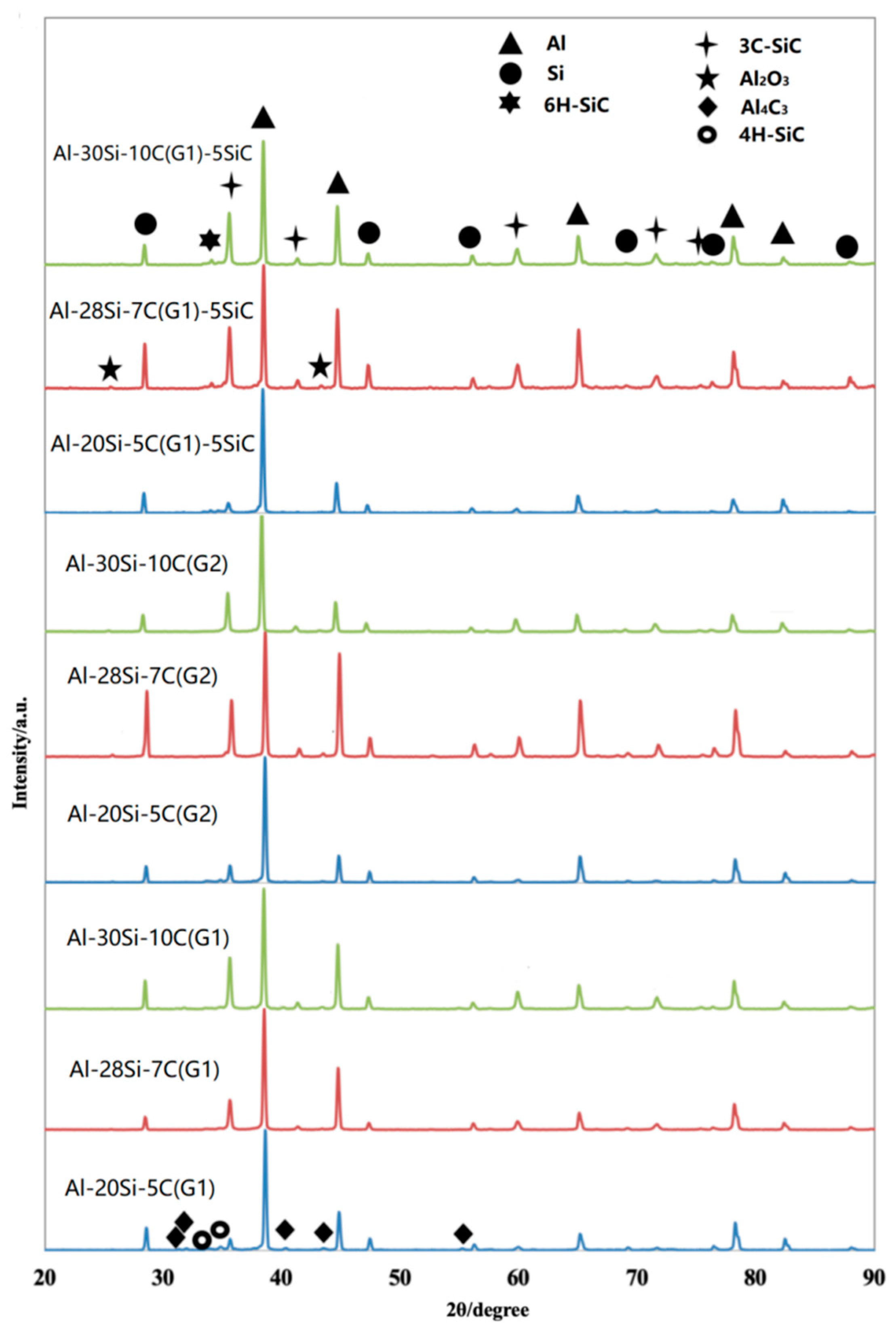
3.1.2. Phase Analysis of the In Situ SiCp/Al-Si Composites

Figure 2 shows the X-ray diffraction (XRD) patterns of samples with different component ratios, as shown in Table 1. Clearly, a 3C-SiC diffraction peak was found, and the intensities of the diffraction peaks were enhanced with an increase in Si and C content. This indicated that a chemical reaction took place in the Al-Si-C system during the preparation process. The peak of 4H-SiC was detected, which suggested that the transformation of SiC crystal type may take place in the process of the in situ reaction. The XRD analysis results demonstrated that in situ SiCp-reinforced AMCs could be fabricated and that the proportion of in situ SiCp in the AMCs could be adjusted by changing the content of carbon and silicon. In addition, there was also a small amount of Al4C3 synthesised in Al-20Si-5C(G1) and Al-30Si-10C(G1), and no diffraction peak of Al4C3 was observed in Al-28Si-7C(G1). For the samples added with G1 or G2, a similar trend was reflected in XRD diagrams. The distribution of the different component ratios of composites in Al-Si-C ternary phase diagram at 1000 °C is shown in Figure 3 [26]. The distribution of Al-20Si-5C(G1), Al-28Si-7C(G1), and Al-30Si-10C(G1) was obtained by drawing auxiliary lines on the Al-Si-C ternary phase diagram. The components of Al-20Si-5C(G1) and Al-30Si-10C(G1) were closer to the L + SiC + Al4C3 area; however, the component of Al-28Si-7C(G1) was in the L + SiC area. Therefore, the XRD analysis results were basically consistent with the phase diagram. Compared with the samples without ex-SiCp, there was no significant difference in the XRD patterns except for the peaks of 6H-SiC from ex-SiCp.

3.1.3. Microstructure of In Situ SiCp Reinforced AMCs

Figure 4 shows the SEM photos of Al-28Si-7C(G1). The irregular particles with relatively bright colours are dispersed in the matrix with a light grey colour, and the particles are uniform. The EDS point scan analysis was performed at Spot 1, and the atomic ratio was close to 1:1, which confirmed that the particles were in situ SiC particles. To further observe the in situ SiC particles, in situ SiCp reinforced AMCs were deeply etched. Figure 5 shows the comparison between in situ SiC particles and the ex situ SiC particles. The ex situ SiCp is much larger than in situ SiCp in size. Both are irregular, and the difference is in their edges and corners. The ex situ SiCp has sharp edges and corners marked by the yellow circle in Figure 5a, and in situ SiCp has a relatively smooth boundary marked by the yellow circle in Figure 5b.

3.1.4. Microstructure of Ex Situ SiCp and In Situ SiCp Reinforced AMCs

Figure 6 shows the SEM photos of Al-28Si-7C(G1)-5SiC. As indicated by the yellow arrows in Figure 6a, the ex situ SiC particles were clearly visible and surrounded by a light layer with a thickness of approximately 1–5 μm, as shown in Figure 6b,c,e. The EDS point scan analysis was performed at Spot 1, as shown in Figure 6e. Only Si and C were detected at Spot 1, and the atomic ratio was almost 1:1, confirming it to be an ex situ SiC particle. Compared with Spot 1, the atomic ratio of Si and C at Spot 2 is also closed to 1:1, but there is a small amount of Al. Therefore, the layer with a light colour is considered to be an in situ SiC layer. In other words, a SiC core-shell structure can be formed, with ex situ SiCp in the centre surrounded by in situ SiC, which was achieved by adding ex situ SiCp into the Al-Si-C system.

3.2. Material Property

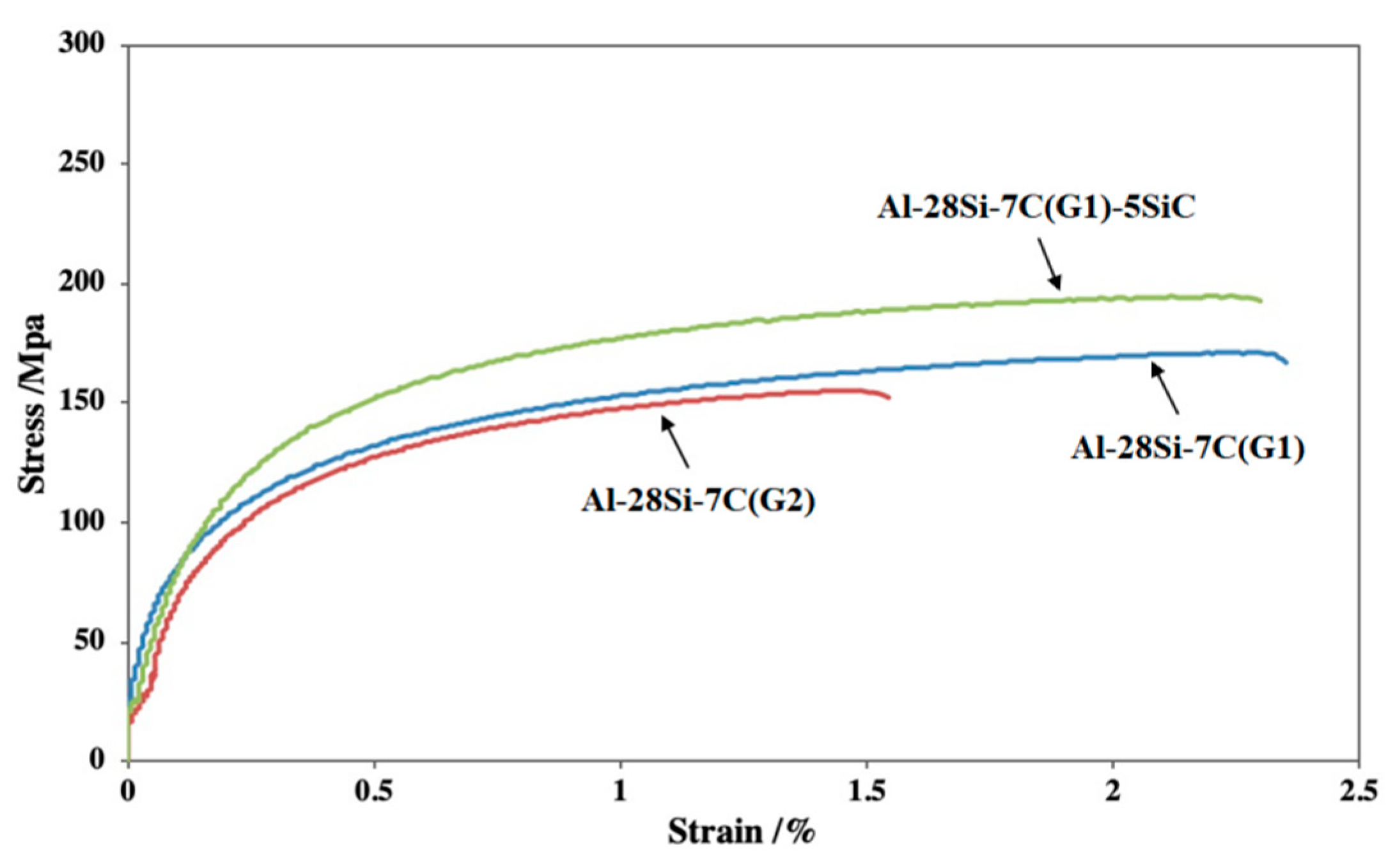
3.2.1. Mechanical Properties of SiCp Reinforced AMCs

The mechanical properties of the samples are shown in Table 2. Al-30Si-10C(G1)-5SiC has the largest tensile strength and yield strength, but its plasticity is the worst. Al-20Si-5C(G1) has the best comprehensive mechanical properties, with a yield strength (YS) of 112 MPa, ultimate tensile strength (UTS) of 180 MPa, and elongation of 4.89%. To synthesise more in situ SiCp in the Al-Si-C system, additional Si and C are necessary, which leads to a decrease in Al content. The plasticity of SiCp-reinforced AMCs comes from Al, and the decrease in Al content is the main reason for the decrease in plasticity. Additionally, the in situ SiCp dispersed in the Al matrix contributes greatly to the strengthening of the composites. On the whole, the ultimate tensile strength and yield strength of SiCp reinforced AMCs with an average graphite size of 6.5 μm are higher than that of 10 μm. The graphite powder size clearly affects the mechanical properties, and a smaller graphite particle size effectively improves the tensile properties of the in situ SiCp/AMCs when the content of silicon and carbon is low. However, for Al-30Si-10C, the ultimate tensile strength and yield strength increase when the average size of graphite is from 6.5 to 10 μm. Firstly, with the increase of silicon and carbon content, the uniform dispersion of particles becomes difficult. At the same time, the smaller the particles are, the easier agglomeration occurs. Secondly, the smaller the particle size is, the larger the surface area is, the more Al4C3 is formed, and the more unreacted Al4C3 is. Therefore, when the silicon and carbon content increase, increasing the graphite particle size can improve the ultimate tensile strength and yield strength.
The tensile stress-strain curves of Al-20Si-5C(G1), Al-20Si-5C(G2), and Al-20Si-5C(G1)-5SiC are shown in Figure 7. It is interesting that an unusual change in the trend occurs for ex situ SiC reinforced AMCs. By comparing Al-20Si-5C(G1) with Al-20Si-5C(G1)-5SiC, it can be found that neither the strength nor ductility increase with the addition of 5% ex situ SiCp. There are few SiC core-shell structures due to the low contents of Si and C in the samples. Moreover, the size of ex situ SiCp is much larger than that of in situ SiCp, and the interfacial bond of the ex situ SiCp and Al matrix is not good without the SiC core-shell structure, which results in a decrease in the strength and ductility of the material.
The tensile stress-strain curves of Al-28Si-7C(G1), Al-28Si-7C(G2), and Al-28Si-7C(G1)-5SiC are shown in Figure 8. Compared with Al-28Si-7C(G1), the strength of Al-28Si-7C(G1)-5SiC is significantly increased with a constant ductility by adding 5% ex situ SiCp. With an increase in Si and C, additional core-shell structures are formed. In the core-shell structure, an in situ SiC layer is formed around the additional SiC particles, which not only realises the combination of SiC particles and the matrix at the atomic level but also blunts the sharp corners of the SiC particles and makes the original irregular particles rounder. Therefore, for Al-28Si-7C(G1)-5SiC, the addition of 5% ex situ SiC increases the mechanical properties of the composite. As the content of Si and C increases, the strength of Al-30Si-10C(G1)-5SiC has a significant increase, and the ductility clearly decreases with the addition of 5% ex situ SiCp. The core-shell structure can increase the strength of Al-30Si-10C(G1)-5SiC, while the decrease in the aluminium matrix greatly reduces its plasticity. The strength can be improved without reducing the plasticity by optimising the proportion of in situ and ex situ SiCp.

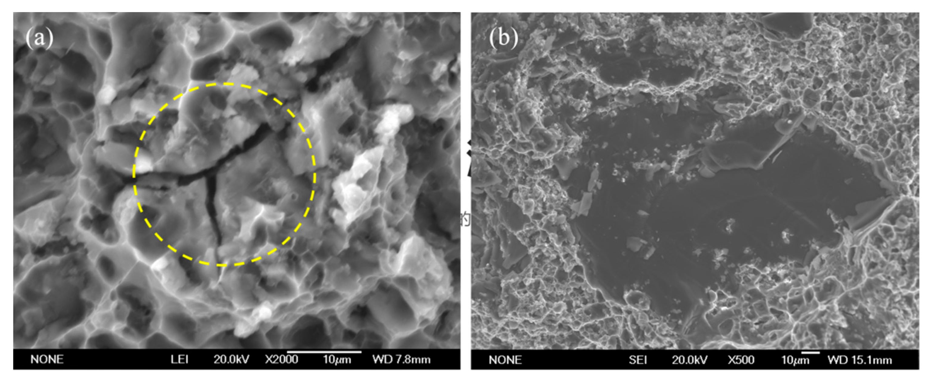
3.2.2. Fracture Mechanism of the SiC Core-Shell Structure/AMCs

SEM images of the fracture surface of the tensile sample are shown in Figure 9. Hybrid-fracture characteristic appears in the fracture surface. Dimples and tear ridges have been observed, which are typical ductile fracture characteristics. Meanwhile, chevron cracking, marked by the yellow circle in Figure 9a, is a typical brittle fracture morphology. Chevron cracking is supposed to be produced from internal microcracks. In the region of large SiC particles, fracture is typical intergranular cleavage, as shown in Figure 9b, which indicates that the increase in Si content can decrease the plasticity of the material. The hybrid-fracture behaviour contributes to improving the mechanical properties.
As shown in Figure 10, the fracture mechanism of AMCs with the reinforcement of the SiC core-shell structure consists of ductile fracture of the Al matrix and cleavage fracture of the SiC core-shell structure. Some in situ SiCp with small sizes are found in the dimples shown in Figure 10c, which indicates classical particle-induced ductile fracture behaviour.

4. Discussion

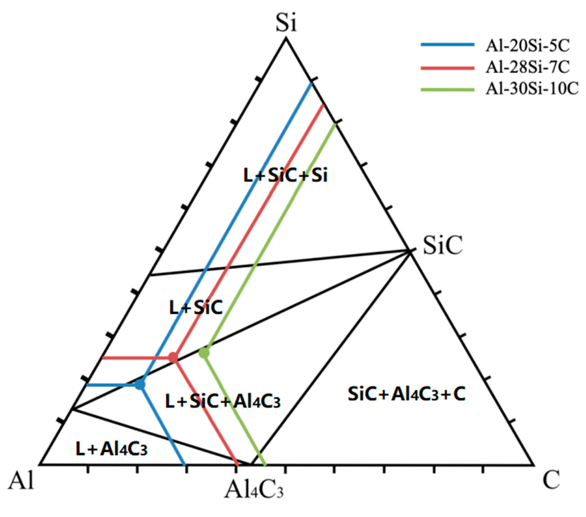
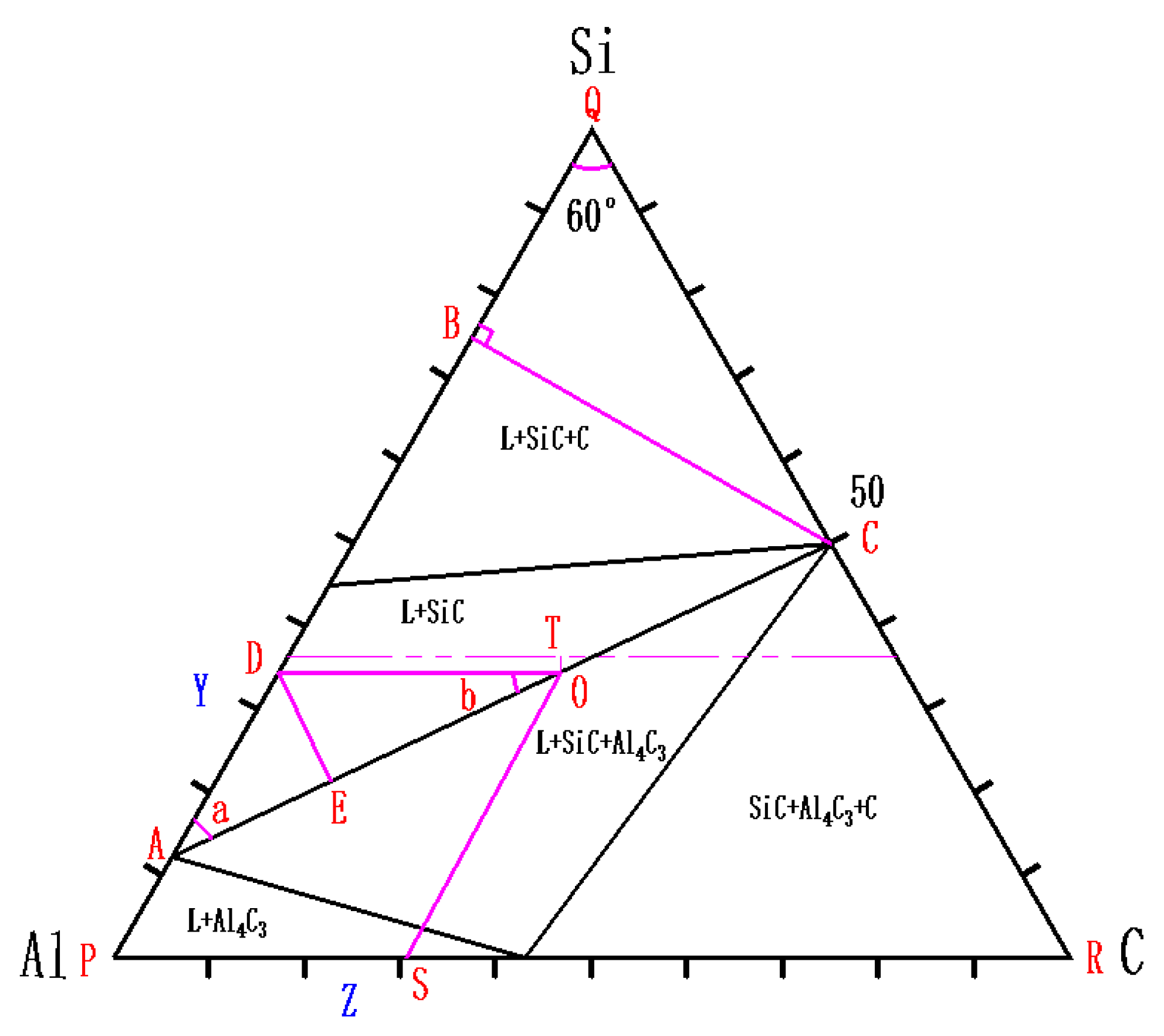
4.1. Conditions for the Complete Reaction of Al4C3

Through the analysis of the phase diagram in Figure 11, there is no Al4C3 above the AC line. Therefore, as long as the functional relations of the three components above the AC line can be found, it can be used as a criterion to determine whether Al4C3 is a complete reaction.
Taking any point O on the straight-line AC, let the mole percentages of Al, Si, and C in the alloy be X%, Y%, and Z%, respectively. It can be derived that the functional relationship of the AC line from the trigonometric relationship of triangle ADE, triangle ODE, and triangle ABC is as follows:
sin 60 ° arctan 3 / 2 × QC 100 PA 1 / 2 QC = sin arctan 3 / 2 × QC 100 PA 1 / 2 QC × ( Y PA ) / Z
where QC is the mole percentages of Si in Al-Si components, PA is the mole percentages of Si in Si-C components.
If QC = 50 and PA = 12.2 are substituted into Equation (7), we obtain:
Y = 12.2 + 0.752 × Z ,
which indicates that the minimum mole percentage of Si without Al4C3 in the alloy is 12.2% when the Z value is zero. Conditions for the complete reaction of Al4C3 are to ensure that the component point is above the line AC, such as point T, so:
Y > 12.2 + 0.752 × Z
Combined with the relationship X + Y + Z = 100 and substituted into Equation (9), we obtain:
Y > 49.88 0.429 × X
and this formula is used for verification.
Only at the mole percentages of Al, Si, and C that satisfy Equations (9) and (10) simultaneously can Al4C3 be completely reacted to form SiC in an Al-Si-C system. Table 3 shows the verification comparison between theoretical calculation results and experimental results on whether Al4C3 is contained in Al-Si-C systems. For Al-20Si-5C and Al-30Si-10C, the mole percentages of Al, Si, and C cannot match Equations (9) and (10), so Al4C3 cannot be completely consumed, which is consistent with the XRD analysis results as shown in Figure 2. Therefore, Equations (9) and (10) can be used as the criterion for whether Al4C3 can be reacted completely.

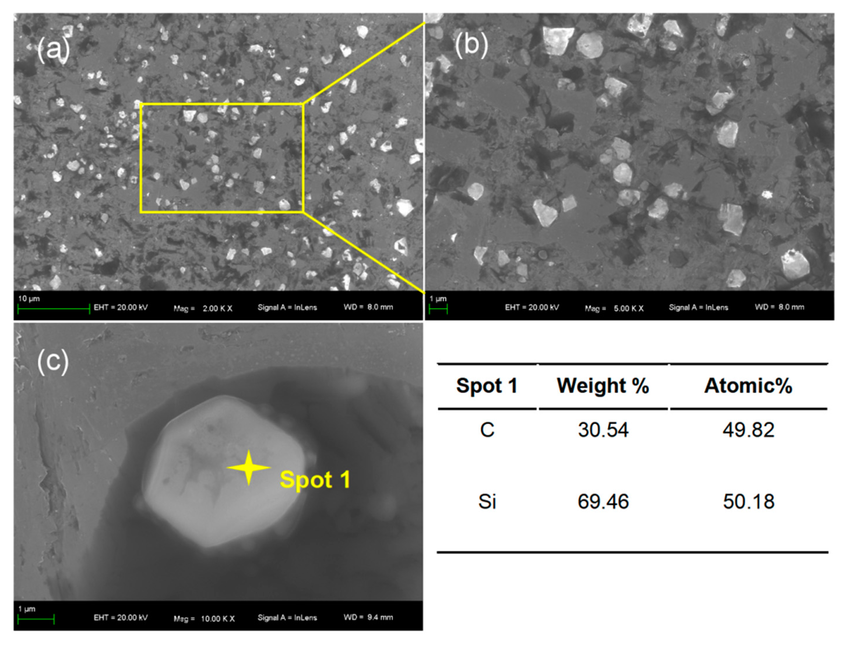
4.2. Analysis of the Synthesised SiC Core-Shell Structure

Al-30Si-10C(G1)-5SiC was chosen to observe the core-shell structure more clearly due to its high carbon and silicon content and large graphite size. As shown in Figure 12a, there are many irregular particles with a light grey inside and a white edge, and the particle size is about 40–60 μm, indicated by the yellow arrow. One of the particles is magnified in Figure 12b,c. From Figure 12b, it can be found that there are many small spots (1–5 μm) around the SiC core-shell structure, such as Spot 2, which was tested by the EDS point scan analysis and proved to be in situ SiC particles because they have the same elemental composition as the in situ SiC layer observed at Spot 1. Figure 12c shows that part of the in situ SiC layer formed around the ex situ SiC particles is discontinuous, which is indicated by the yellow dotted circles. Therefore, it is considered that the nucleation and growth of in situ SiCp formed around the ex situ SiCp leads to the formation of an in situ SiC layer.
Figure 13 shows EDS mapping of Al-30Si-10C(G1)-5SiC. It can be seen that there is only Si and C in the irregular particle area from the distribution of elements, and the content of Si decreases at the edge of the particle. Three points at the edge were selected for EDS point scan analysis. Spot 1 was on the edge of the particle, and the distance from Spot 2 and Spot 3 to the particle became farther in turn. At Spot 1, the content of Si and C is about 1:1, the content of Si is slightly lower, and there is a small amount of Al. When SiCp is added to a certain acid mixture of HNO3 and HF, the Si atoms on the Si-terminated surface can react as chemical reactions 1 and 2. Thus, the C atoms on the Si-terminated surface are exposed. C will react with Al easily by the following chemical reaction: 3C + 4Al Al4C3. Similarly, the C atoms on the C-terminated surface and the C atoms exposed on the Si-terminated surface because of the reaction of Si with the acids may also react with Al to form Al4C3 around the ex situ SiCp. The core-shell structure that SiC as the core and Al4C3 as the core can be recorded as SiC@Al4C3, where @ represents the core-shell structure. Then, Si atoms around the particles continue to react with Al4C3 to form SiC and Al through diffusion by the following reaction: Al4C3 + 3Si 3SiC + 4Al, so the Si content near the particles decreases and the Al content increases, which is consistent with the EDS point scan analysis of Spot 2. Spot 3 is relatively far away from the particles because the diffusion of silicon takes time, so the content of Si is slightly lower, which is close to the original composition. With the growth of the in situ SiCp formed around ex situ SiCp, the SiC layer is finally synthesised, thereby obtaining the SiC core-shell structure, recorded SiC@in situ SiC. Through the change of Si content around the core-shell structure, we can conclude that the formation of the core-shell structure is mainly completed by the diffusion of silicon. Figure 14 shows a schematic diagram showing the formation mechanism of the SiC core-shell structure.

5. Conclusions

SiCp/AMCs were prepared with different volume fractions of SiCp by combining in situ synthesis and external methods. XRD analysis confirmed the existence of Al4C3 in the process of the in situ reaction and the two-step indirect reaction of SiC formation. SEM and EDS point scan analysis showed that in situ SiCp with a smooth boundary could be obtained via the Al-Si-C system by powder metallurgy and that the in situ SiC layer adhered to the added SiC particles, which closely coalesced with the original particles. Mechanical property testing showed that the elongation decreased by 50%, and the strength decreased by 12% when the volume fraction of SiC was increased from 15% to 20%. When the composite is Al-28Si-7C, the yield strength and ultimate tensile strength of in situ SiCp AMCs can be significantly increased with a constant ductility by adding 5% ex situ SiCp. The analyses show that there are few SiC core-shell structures when the content of Si and C is low. Moreover, the size of ex situ SiCp is much larger than that of in situ SiCp, and the interfacial bond of the ex situ SiCp and Al matrix is not good without the SiC core-shell structure, which results in a decrease in the strength and ductility of the material. With the content of Si and C increase, although a better core-shell structure can be formed, the elongation and plasticity still decrease because of the reduction of the aluminium matrix content. In the core-shell structure, an in situ SiC layer was formed around the additional SiC particles, which not only realised the combination of SiC particles and the matrix at the atomic level but also rounded the sharp corners of the SiC particles, making the original irregular particles rounder. The formation of the core-shell structure is mainly formed by the diffusion of silicon through an indirect reaction: 4Al + 3C → Al4C3 and Al4C3 + 3Si → 3SiC + 4Al. It is also found that decreasing the graphite powder size can improve the tensile properties of in situ SiCp/AMCs for Al-20Si-5C and Al-28Si-7C.

Author Contributions

Conceptualization, S.L.; writing—original draft preparation, C.Z.; writing—review and editing, X.J.; software, C.Z. and X.J.; supervision, S.L.; project administration, S.L.; visualization, S.L. and X.J., funding acquisition, S.L. and X.J. All authors have read and agreed to the published version of the manuscript.

Funding

This research was funded by the National Natural Science Foundation of China (Nos. 51571160 and 51871180), Natural Science Basic Research Plan in Shaanxi Province of China (No. 2015JM5233), and Research Fund for Young Teachers of Laiwu Vocational and Technical College (No. 2020qnzx02, No. 2019jsky04).

Institutional Review Board Statement

Not applicable.

Informed Consent Statement

Not applicable.

Data Availability Statement

The raw/processed data required to reproduce these findings cannot be shared at this time as the data also forms part of an ongoing study.

Conflicts of Interest

The authors declare no conflict of interest.

References

  1. Park, J.; Lee, S.; Lee, M.; Rhee, C. Dispersion of ultrafine SiC particles in molten Al-12Si alloy. Trans. Nonferrous Met. Soc. China 2011, 11, 33–36. [Google Scholar] [CrossRef]
  2. Chen, G.; Chang, X.; Zhang, J.; Jin, Y.; Sun, C.; Chen, Q.; Zhao, Z. Microstructures and Mechanical Properties of In-Situ Al3Ti/2024 Aluminum Matrix Composites Fabricated by Ultrasonic Treatment and Subsequent Squeeze Casting. Met. Mater. Int. 2020, 26, 1574–1584. [Google Scholar] [CrossRef]
  3. Du, X.; Gao, T.; Li, D.; Wu, Y.; Liu, X. A novel approach to synthesize SiC particles by in situ reaction in Al-Si-C alloys. J. Alloys Compd. 2014, 588, 374–377. [Google Scholar] [CrossRef]
  4. Tzamtzis, S.; Barekar, N.S.; Hari Babu, N.; Patel, J.; Dhindaw, B.K.; Fan, Z. Processing of advanced Al/SiC particulate metal matrix composites under intensive shearing-A novel rheo-process. Compos. Part A 2009, 40, 144–151. [Google Scholar] [CrossRef]
  5. Wang, W.; Li, Q.; Ma, R.; Cui, Y.; Cao, X.; Wang, X. Effects of the Si contents of an infiltrating aluminium alloy on the microstructure and strength of SiC matrix composites. Ceram. Int. 2017, 43, 12526–12533. [Google Scholar] [CrossRef]
  6. Huei-Long, L.; Wun-Hwa, L.; Chan, S.L.I. Abrasive wear of powder metallurgy Al alloy 6061-SiC particle composites. Wear 1992, 159, 223–231. [Google Scholar] [CrossRef]
  7. Wang, T. Preparation and Properties of SiCp/Al Composites with High Volume Fraction by Powder Metallurgy Method. Ph.D. Thesis, Xi’an University of Technology, Xi’an, China, 2018. [Google Scholar]
  8. Jiju, K.B.; Selvakumar, G.; Prakash, S.R. Study on preparation of Al-SiC metal matrix composites using powder metallurgy technique and its mechanical properties. Materialstoday 2020, 27, 1843–1847. [Google Scholar] [CrossRef]
  9. Chen, Z.Z.; Tokaji, K. Effects of particle size on fatigue crack initiation and small crack growth in SiC particulate-reinforced aluminium alloy composites. Mater. Lett. 2004, 58, 2314–2321. [Google Scholar] [CrossRef]
  10. Yang, Y.; Lan, J.; Li, X. Study on bulk aluminum matrix nano-composite fabricated by ultrasonic dispersion of nano-sized SiC particles in molten aluminum. Mater. Sci. Eng. A 2004, 380, 378–383. [Google Scholar] [CrossRef]
  11. Hu, Q.; Zhao, H.; Li, F. Microstructures and properties of sic particles reinforced aluminum-matrix composites fabricated by vacuum-assisted high pressure die casting. Mater. Sci. Eng. A 2017, 680, 270–277. [Google Scholar] [CrossRef]
  12. Lee, J.C.; Byun, J.Y.; Oh, C.S.; Seok, H.K.; Lee, H.I. Effect of various processing methods on the interfacial reactions in SiCp/2024Al composites. Acta Mater. 1997, 45, 5303–5315. [Google Scholar] [CrossRef]
  13. Zhu, J.; Wang, F.; Wang, Y.; Zhang, B.; Wang, L. Interfacial structure and stability of a co-continuous SiC/Al composite prepared by Vacuum-pressure infiltration. Ceram. Int. 2017, 43, 6563–6570. [Google Scholar] [CrossRef]
  14. Guo, X.; Wang, L.; Wang, M.; Qin, J.; Zhang, D.; Lu, W. Effects of degree of deformation on the microstructure, mechanical properties and texture of hybrid-reinforced titanium matrix composites. Acta Mater. 2012, 60, 2656–2667. [Google Scholar] [CrossRef]
  15. Li, S.; Sun, B.; Imai, H.; Kondoh, K. Powder metallurgy Ti–TiC metal matrix composites prepared by in situ reactive processing of Ti-VGCFs system. Carbon 2013, 61, 216–228. [Google Scholar] [CrossRef]
  16. Ma, Z.Y.; Tjong, S.C.; Gen, L. In-situ Ti-TiB Metal–Matrix composite prepared by a reactive pressing process. Scr. Mater. 2000, 42, 367–373. [Google Scholar] [CrossRef]
  17. Sha, J.J.; Zhang, Z.F.; Di, S.X.; Lv, Z.Z.; Li, J.; Dai, J.X. Microstructure and mechanical properties of ZrB2-based ceramic composites with nano-sized SiC particles synthesized by in-situ reaction. Mater. Sci. Eng. A 2017, 693, 145–150. [Google Scholar] [CrossRef]
  18. Ren, R.; Xiang, D.; Cao, Y.; Hu, Y. In-situ growth and relevant mechanisms of thick SiC nanowhiskers from hybrid silicon sources. J. Alloys Compd. 2020, 857, 157577. [Google Scholar] [CrossRef]
  19. Gustafsson, S.; Falk, L.K.; Lidén, E.; Carlström, E. Alumina/silicon carbide composites fabricated via in situ synthesis of nano-sized SiC particles. Ceram. Int. 2009, 35, 1293–1296. [Google Scholar] [CrossRef]
  20. Du, X.; Gao, T.; Qian, Z.; Wu, Y.; Liu, X. The in-situ synthesis and strengthening mechanism of the multi-scale SiC particles in Al-Si-C alloys. J. Alloys Compd. 2018, 750, 935–944. [Google Scholar] [CrossRef]
  21. Gao, T.; Wang, D.; Du, X.; Li, D.; Liu, X. Phase transformation mechanism of Al4C3 by the diffusion of Si and a novel method for in situ synthesis of SiC particles in Al melt. J. Alloys Compd. 2016, 685, 91–96. [Google Scholar] [CrossRef]
  22. Mokhnache, E.O.; Wang, G.S.; Lin, G.E.N.G. Wearing resistance of in-situ Al-based composites with different SiO2/C/Al molar ratios fabricated by reaction hot pressing. Trans. Nonferrous Met. Soc. China 2016, 26, 917–923. [Google Scholar] [CrossRef]
  23. Wu, C.; Gao, T.; Liu, X. In-situ SiC reinforced Si-SiC 3D skeletons in SiC/Al-Si composites. J. Alloys Compd. 2019, 810, 151730. [Google Scholar] [CrossRef]
  24. Oden, L.; McCune, R. Phase-equilibria in the Al-Si-C system. Metall. Trans. A 1987, 18, 2005–2014. [Google Scholar] [CrossRef]
  25. Zhou, X.; Zang, J.; Dong, L.; Cheng, X.; Li, T.; Wang, Y.; Yuan, Y.; Lu, J.; Yu, Y.; Xu, X. Fabrication of bulk nano-SiC via in-situ reaction of core-shell structural SiC@C with Si using high pressure high temperature sintering method. Mater. Lett. 2015, 144, 69–73. [Google Scholar] [CrossRef]
  26. Petzow, G.; Effenberg, G. Ternary Alloys; VCH Verlagsgesellschaft: Weinheim, Germany, 1990; Volume 3, pp. 540–548. [Google Scholar]
Figure 1. SEM images of the raw materials: (a) raw Al, (b) raw Si, (c) raw graphite 1 (G1), (d) raw graphite 2 (G2), (e) Al-Si-C premixed powder, and (f) ex situ SiC powder.
Metals 11 01201 g001
Figure 2. X-ray diffraction patterns of the samples with different component ratios.
Metals 11 01201 g002
Figure 3. Distribution of the different component ratios of composites (Al-20Si-5C, Al-28Si-7C, Al-30Si-10C, wt%) in the Al-Si-C ternary phase diagram at 1000 °C [26].
Metals 11 01201 g003
Figure 4. SEM images and EDS point scan analysis ofAl-28Si-7C(G1): (a) SEM image, (b) SEM image, and (c) SEM image of Al-28Si-7C(G1) and EDS point scan analysis.
Metals 11 01201 g004
Figure 5. SEM images of ex situ SiC particles and in situ SiC particles: (a) Ex situ SiC particles, (b) In situ SiC particles.
Metals 11 01201 g005
Figure 6. SEM images and EDS point scan analysis of Al-28Si-7C(G1)-5SiC: (a) 200X SEM image, (b) 1000× SEM image, (c) 5000× SEM image, (d) 30,000× SEM image, and (e) EDS point scan analysis.
Metals 11 01201 g006
Figure 7. Tensile stress-strain curves of Al-20Si-5C(G1), Al-20Si-5C(G2), and Al-20Si-5C(G1)-5SiC.
Metals 11 01201 g007
Figure 8. Tensile stress-strain curves of the SiC/AMCs.
Metals 11 01201 g008
Figure 9. SEM images of the fracture surface of in situ SiCp-reinforced AMCs: (a) SEM image of Al-20Si-5C(G1) and (b) SEM image of Al-28Si-7C(G1).
Metals 11 01201 g009
Figure 10. SEM images of the fracture of core-shell SiC (SiC@In situ SiC)-reinforced AMCs (Al-28Si-7C(G1)-5SiC): (a) SEM image of Al-28Si-7C(G1)-5SiC, (b,c) SEM images of Al-28Si-7C(G1)-5SiC, and (d) SEM image of Al-28Si-7C(G1)-5SiC.
Metals 11 01201 g010
Figure 11. Al-Si-C ternary phase diagram at 1000 °C.
Metals 11 01201 g011
Figure 12. SEM images and EDS point scan analysis of Al-30Si-10C(G1)-5SiC: (a) 140× SEM image, (b) 1000× SEM image and EDS point scan analysis, and (c) 2000× SEM image.
Metals 11 01201 g012
Figure 13. SEM image and EDS mapping analysis of Al-30Si-10C(G1)-5SiC.
Metals 11 01201 g013
Figure 14. Schematic diagram showing the formation mechanism of the SiC core-shell structure (SiC@In situ SiC).
Metals 11 01201 g014
Table 1. AMC samples prepared from different starting powders.
SampleAl (wt%)Si (wt%)C (wt%)Ex-SiC
Al-20Si-5C(G1)75205 (~6.5 μm)Without
Al-28Si-7C(G1)65287 (~6.5 μm)Without
Al-30Si-10C(G1)603010 (~6.5 μm)Without
Al-20Si-5C(G2)75205 (~10 μm)Without
Al-28Si-7C(G2)65287 (~10 μm)Without
Al-30Si-10C(G2)603010 (~10 μm)Without
Al-20Si-5C(G1)-5SiC75205 (~6.5 μm)5 (~40 μm)
Al-28Si-7C(G1)-5SiC65287 (~6.5 μm)5 (~40 μm)
Al-30Si-10C(G1)-5SiC603010 (~6.5 μm)5 (~40 μm)
Table 2. Yield strength (YS), ultimate tensile strength (UTS), elongation, and relative density of samples.
SampleYS (MPa)UTS (MPa)Elongation (%)Relative Density (%)
Al-20Si-5C(G1)112 ± 2180 ± 34.9 ± 0.599.38
Al-28Si-7C(G1)128 ± 1172 ± 22.1 ± 0.399.76
Al-30Si-10C(G1)123 ± 1167 ± 21.8 ± 0.397.11
Al-20Si-5C(G2)109 ± 2169 ± 24.6 ± 0.498.78
Al-28Si-7C(G2)120 ± 1156 ± 21.5 ± 0.399.59
Al-30Si-10C(G2)138 ± 2169 ± 10.8 ± 0.397.80
Al-20Si-5C(G1)-5SiC113 ± 2160 ± 33.3 ± 0.499.03
Al-28Si-7C(G1)-5SiC141 ± 3192 ± 32.1 ± 0.399.53
Al-30Si-10C(G1)-5SiC211 ± 3237 ± 20.6 ± 0.297.63
Table 3. Verification comparison between theoretical calculation results and experimental results on whether Al4C3 is contained in Al-Si-C system.
SampleXYZ Y > 12.2 + 0.752 × Z
(Yes/No)
Y > 49.88 0.429 × X
(Yes/No)
Theoretical ResultTest Result
Al-20Si-5C70.618.810.6NoNoWith Al4C3With Al4C3
Al-28Si-7C60.325.114.6YesYesWithout Al4C3Without Al4C3
Al-30Si-10C53.426.719.9NoNoWith Al4C3With Al4C3
Publisher’s Note: MDPI stays neutral with regard to jurisdictional claims in published maps and institutional affiliations.

