Article

An Investigation into the Effect of Rolling Reduction on 3D Curved Parts Rolling Process

1
Roll Forging Research Institute, Jilin University, Changchun 130025, China
2
College of Materials Science and Engineering, Jilin University, Changchun 130025, China
*
Authors to whom correspondence should be addressed.
Metals 2021, 11(8), 1209; https://doi.org/10.3390/met11081209
Submission received: 22 June 2021 / Revised: 22 July 2021 / Accepted: 26 July 2021 / Published: 29 July 2021

Abstract

:
Rolling technology based on arc-shaped rollers is a novel method for rapid manufacturing of 3D curved parts. The method uses a pair of arc-shaped rollers (a convex roller and a concave roller) as forming tools, forming an unevenly distributed roll gap. The sheet metal has both transverse bending and longitudinal uneven extension during rolling, so that surface parts with double curvature are processed. The curvature of the formed surface part can be changed by changing the rolling reduction. Changing the vertical distance between the rollers will cause the overall change of the roll gap height, which will inevitably have a great impact on the forming effect of formed 3D curved parts. In this paper, a finite element model and experiment with different rolling reductions was designed; the influence of rolling reduction on the bending deformation and shape accuracy of formed 3D curved parts was studied. The results show that, with the slight increase of rolling reduction (from 0.04 to 0.12 mm), the longitudinal bending deformation of the formed 3D curved part increases significantly, but its transversal bending is almost not affected. When the maximum rolling reduction is 0.04 and 0.06 mm (the corresponding minimum rolling reduction is less than or equal to zero), the shape accuracy of the formed 3D curved parts is not good enough; when the maximum rolling reduction is greater than 0.06 mm (the corresponding minimum rolling reduction is greater than zero), the shape accuracy of the formed 3D curved parts is significantly better. This indicates that, for the rolling of 3D curved parts based on arc-shaped rollers, ensuring that the minimum rolling reduction is greater than zero is the key to ensuring good shape accuracy of the formed 3D curved parts.

1. Introduction

3D curved parts are widely used in aviation, aerospace, shipbuilding, high-speed trains, construction, and other industries. Conventional forming technology is mainly used to manufacture a single variety of 3D curved parts in large quantities. Because of the high mold manufacturing cost and long production cycle, conventional forming technology is not suitable for processing multi-variety and small-batch 3D curved parts. However, with the increasing market demand for product diversification and individualization, there is an increasing demand for multi-variety and small-batch 3D curved parts. Many industrial fields have an urgent need for fast and low-cost 3D curved parts forming technology [1,2,3,4].
Therefore, flexible forming technology has received extensive attention from many scholars. The discussion of using flexible molds to form 3D curved parts can be traced back to the research of Nakajima et al. [5], who proposed the method of using a large number of metal bars to construct flexible molds. Finckenstein et al. [6] applied this idea to the punch design of deep drawing forming. Walczyk et al. [7] applied it to the die design of aircraft skin stretch forming. Li et al. [8,9,10] applied it to multi-point forming (MPF). Compared with traditional molding methods, MPF is very suitable for the production of small batches of 3D curved parts, but its equipment structure is complex and the cost is extremely high. Therefore, rolling technology of 3D curved parts has received more attention and research in recent years.
Yamashita et al. [11] first proposed the use of roll forming technology to produce 3D curved parts. Yoon et al. [12] developed an incremental 3D surface parts roll forming process. Li et al. [13] developed a continuous flexible forming process using a small diameter bendable roller made of steel wire as the forming rollers. Shim et al. [14] developed an array rolling process for forming 3D curved parts. Li et al. [15,16] proposed a flexible rolling technology (FRT) that uses only two bendable flexible rollers to produce 3D curved parts. This method uses bendable flexible rollers to form unevenly distributed roll gaps to achieve roll forming of 3D curved parts. By adjusting the bending shape of the flexible rollers, different types of roll gap shapes can be combined to realize the rolling forming of different types and specifications of 3D curved parts [17,18]. However, in order to achieve the transverse bending and torque transmission, the forming device can only use small diameter rollers as forming tools, which means that it can only transmit a small torque. Thus, FRT is only suitable for cold rolling of sheet metals with low hardness and small thickness.
Therefore, Li and his colleague et al. [19] developed rolling technology of 3D curved parts with rigid arc-shaped rollers (RTRAR) based on the FRT. The RTRAR uses a pair of arc-shaped rollers as forming tools to make the sheet metals produce continuous plastic deformation along the rolling direction (longitudinal direction) and, simultaneously, produce bending deformation perpendicular to the rolling direction (transverse direction); thereby, surface parts with double curvature are obtained. An unevenly distributed roll gap is formed by a convex roller and a concave roller. Owing to the uneven distribution of the roll gap, different points on the same cross section of the sheet metal during the rolling process will produce different reduction in the thickness direction, resulting in different longitudinal extending. Under the combined action of the transverse bending deformation and the longitudinal uneven elongation deformation, the additional stress generated causes the sheet metal to cause 3D deformation (see Figure 1). RTRAR’s equipment has a simpler structure, better rigidity, and lower cost.
In the FRT, the size of the roll gap can be adjusted freely. Further, studies on the FRT are all based on the minimum rolling reduction of the sheet metal being zero [20,21,22,23,24]. The process of RTRAR is different from the FRT. In RTRAR, because the rollers are rigid, the change of height of roll gap (rolling reduction) always changes as a whole. Therefore, it is necessary to investigate the influence of rolling reduction on the forming effect of formed 3D curved parts. In this paper, the process parameter of the rolling reduction is investigated. A series of rolling reductions are simulated and experimented. The bending deformation and shape accuracy of 3D curved parts formed by different rolling reductions are compared, and their differences are analyzed through simulation results and experimental results.

2. Forming Theory of 3D Curved Parts Rolling by Arc-Shaped Rollers

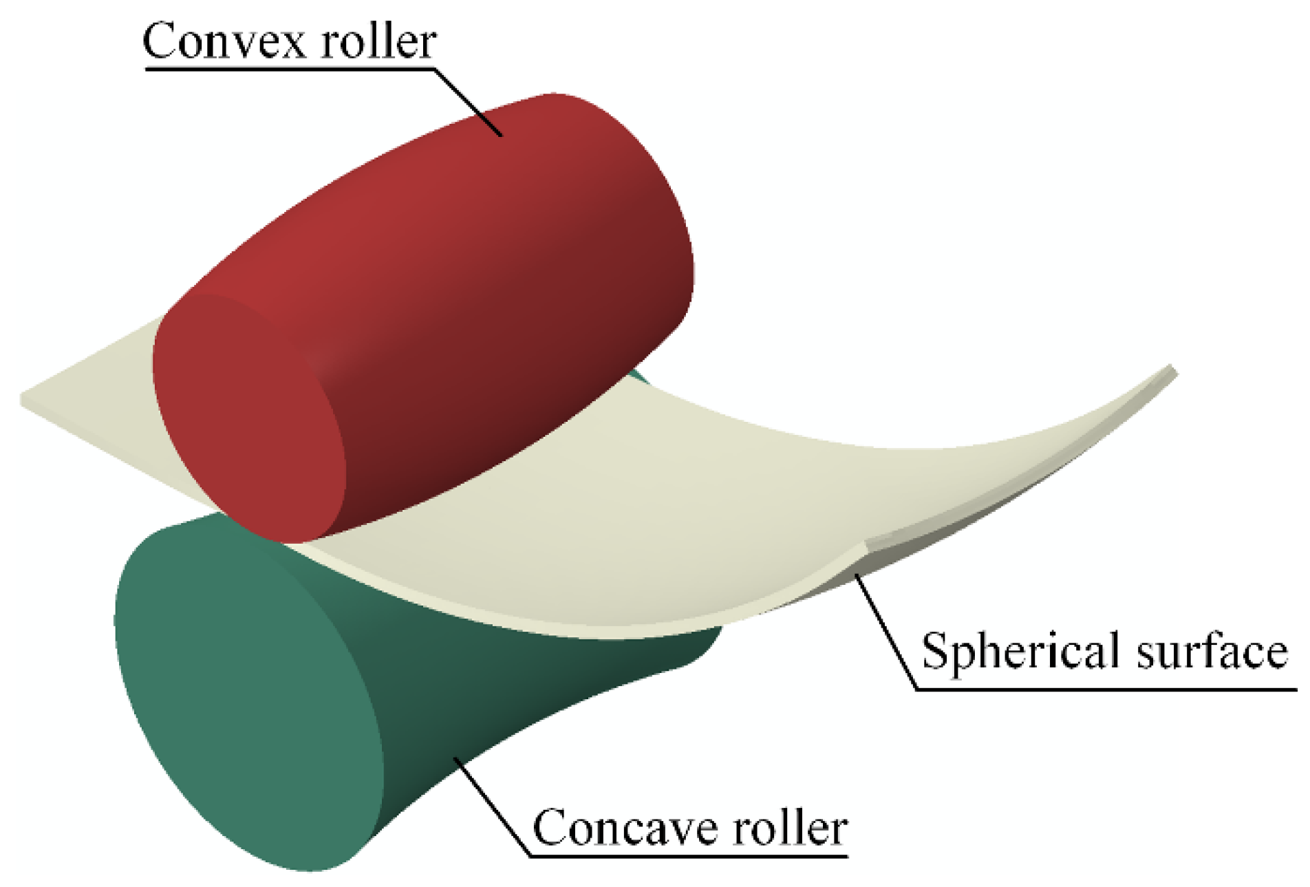
2.1. Basic Principle of 3D Surface Rolling

Figure 2 shows the correspondence between the roll gap distribution and the processed 3D curved part. When the roll gap is small in the middle and big in the edges, the formed part is a spherical part; when the roll gap is big in the middle and small in the edges, the formed part is a saddle-shaped part.

2.2. Mathematical Description of Roll Gap

Taking the intersection point O of the longitudinal centerline of the lower surface of the sheet metal and the arc curve of the upper border of the concave roller as the coordinate origin, the coordinate system shown in Figure 3 is established, where X, Y, and Z directions represent the transverse direction, thickness direction, and longitudinal direction, respectively.
The expression of the lower border arc of the convex roller is
x 2 + [ y ( R 1 + H 1 ) ] 2 = R 1 2 ( y < H 1 + R 1 )
The expression of the upper border arc of the concave roller is
x 2 + ( y R 2 ) 2 = R 2 2 ( y < R 2 )
The lower border function of the convex roller is recorded as L1(x), and the curve L1(x) is symmetric about the Y axis and passes through the point O1(0, H1), so L1(x) can be expressed as
L 1 ( x ) = R 1 + H 1 R 1 2 x 2
In Equation (3), R1 is the generatrix radius of the convex roller and H1 is the thickness at the center of the sheet metal in the roll gap.
The upper border function of the concave roller is recorded as L2(x), and the curve L2(x) is symmetric about the Y axis and passes through the point O(0, 0), so L2(x) can be expressed as
L 2 ( x ) = R 2 R 2 2 x 2
In Equation (4), R2 is the generatrix radius of the concave roller.
The roll gap height function along the vertical direction can be expressed as
H ( x ) = L 1 ( x ) L 2 ( x ) = R 1 + H 1 R 2 + R 2 2 x 2 R 1 2 x 2
According to the principle of similar triangles, the function of the roll gap height along the normal direction can be expressed as
H f ( x ) = 1 R 1 H ( x ) R 1 2 x 2
Suppose the rolling reduction at the center of the sheet metal is Δh, and the initial thickness of the sheet is H0, then the roll gap height along the normal direction can be expressed as
H f ( x ) = 1 R 1 R 1 2 x 2 ( R 1 + H 0 Δ h R 2 + R 2 2 x 2 R 1 2 x 2 )

3. Numerical Simulations

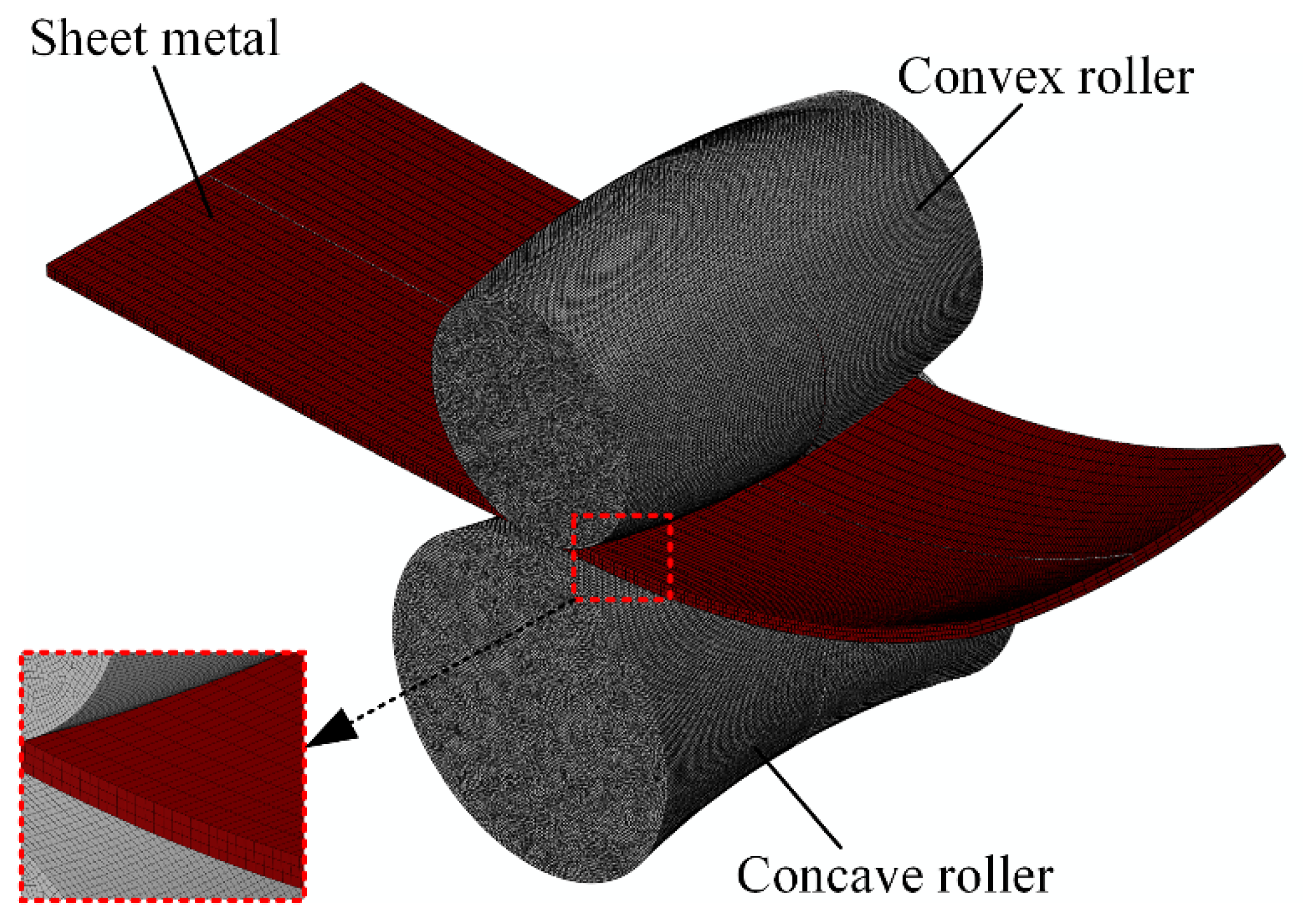
3.1. Finite Element Model

According to the forming process of RTRAR, a 3D elastic-plastic finite element model is established by ABAQUS/Explicit (Version 6.14-2, Dassault Systèmes Simulia Corp., Providence, RI, USA), consisting of a sheet metal, a convex roller, and a concave roller (see Figure 4). The sheet metal is modeled as a deformable body with size of 250 mm × 80 mm × 2.7 mm, and the C3D8R solid element (eight-node linear brick, reduced integration, hourglass control) is used to mesh it. The sheet metal meshes into four layers in the thickness direction, and the mesh sizes in the length and width directions are 0.6 and 1.8 mm, respectively. The material of the sheet metal is annealed 2024 aluminum; its mechanical properties and true stress-strain curve at room temperature obtained by tensile test are shown in Table 1 and Figure 5, respectively.
The generatrix radiuses of the convex and concave roller (see Figure 3) are 206 mm and 212 mm, respectively. The rollers are modeled as discrete rigid bodies, and the R3D4 (four-node 3D bilinear quadrilateral) rigid element is used to mesh them. In order to improve the accuracy of the calculation, the element size of the rollers is set to 0.6 mm × 0.6 mm. The angular velocity of the rollers is set to 10 rad/s, which is selected according to the quasi-static conditions of the sheet metal forming process as recommended by Abaqus Analysis User’s Guide.
Using the penalty friction formula and the Coulomb friction model, according to engineering experience, the friction coefficient is assumed to be 0.12. Owing to the inherent symmetrical structure of the sheet metal and the rollers, and the symmetrical boundary and load conditions, only one-half of the finite element model needs to be considered to improve the calculation efficiency.

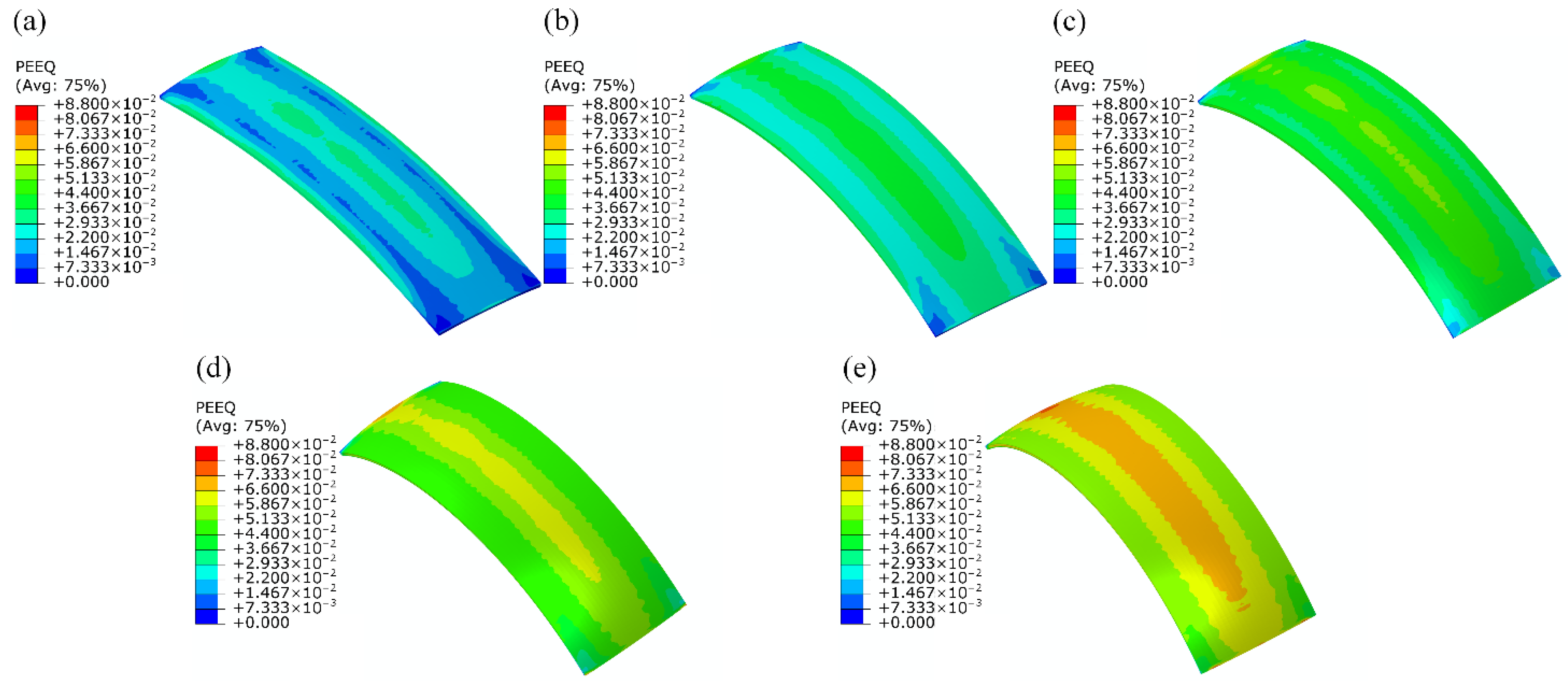
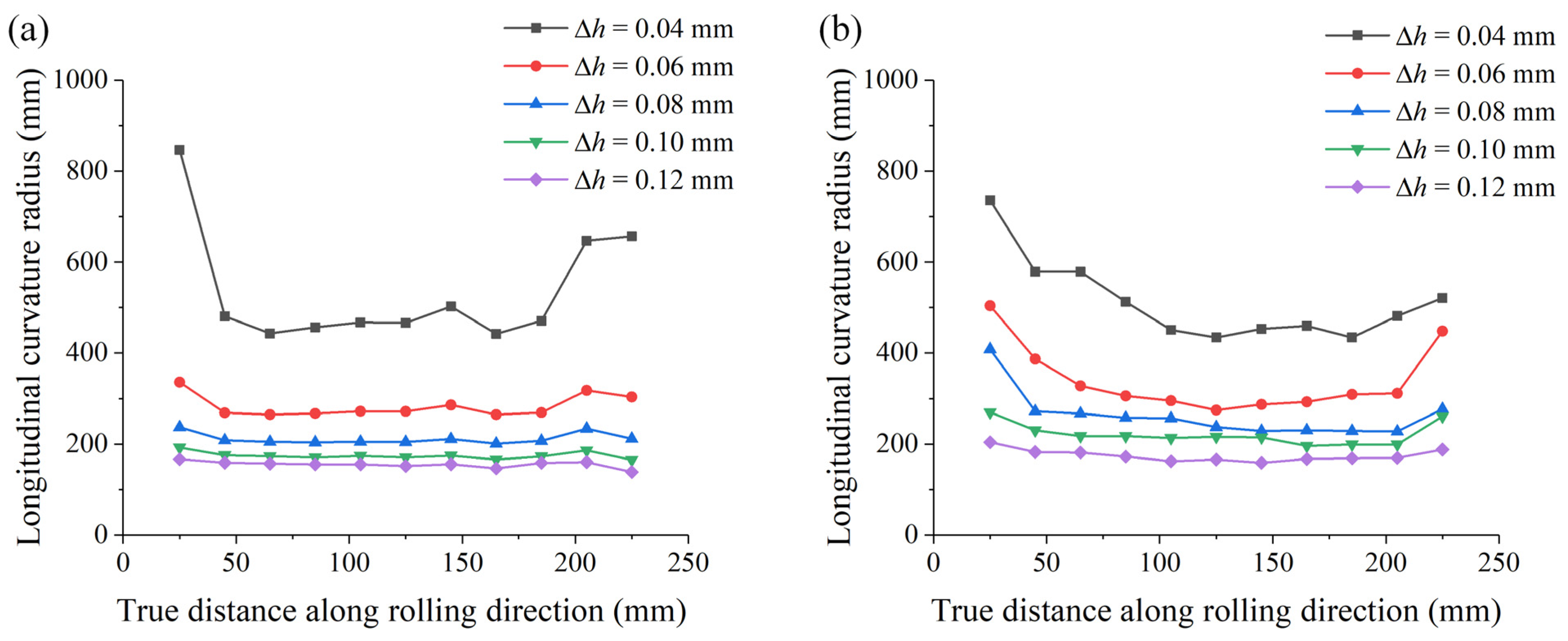
3.2. Analysis of Simulation Results

It is necessary to analyze the stress and strain distribution of each region in the formed sheet metals to study their deformation situation. However, this distribution is not easy to obtain in experiments. Thus, numerical calculations are required for efficient analysis.
Five different center rolling reductions (0.04, 0.06, 0.08, 0.10, and 0.12 mm) are selected to investigate the influence of rolling reduction on the forming effect of 3D curved parts. According to the roll gap height function, the center rolling reductions (Δh) and the corresponding edge rolling reductions (ΔH) can be calculated (see Table 2), where Δh is the center rolling reduction and ΔH is the edge rolling reduction. When Δh = 0.04 mm, the edge of the sheet metal is not squeezed by the rollers during rolling, so ΔH is negative; when Δh = 0.06 mm, the edge rolling reduction is 0, and the edge of the sheet metal is just pressed during rolling; when Δh > 0.06 mm, the edge of the sheet metal is completely compressed by the convex roller during, so their edge reductions are positive.
Figure 6 shows the equivalent plastic strain distribution of the formed spherical parts with five different rolling reductions. It can be seen from Figure 6 that the plastic strain of the formed part increases with the increase of the rolling reduction, and the larger the rolling reduction, the more uniform the equivalent plastic strain distribution. The centerline profile of the formed part in the numerical simulation results is shown in Figure 7, and the curve data are taken from the longitudinal and transversal center positions of the surface parts. It can be seen from Figure 7a that the longitudinal bending deformation of the formed part increases significantly with the increase of the rolling reduction. This is because the longitudinal extension of the formed spherical part gradually decreases from the center to both sides (see Figure 8a), and the difference between the maximum and minimum longitudinal extension increases with the increase of the rolling reduction (see Figure 8b). However, its transversal bending deformation is little affected by the rolling reduction (see Figure 7b), which can almost be ignored. Therefore, the following discussion in this paper only analyses the influence of the rolling reduction on the longitudinal bending deformation of the formed parts.
In order to analyze the forming accuracy of the processed parts more conveniently, the concept of longitudinal curvature radius deviation is introduced. The calculation formula for longitudinal curvature radius deviation is shown in Equation (8):
E L = | R L i R L | R L
In Equation (8), EL represents the deviation of the longitudinal curvature radius, RLi represents the fitting value of the local longitudinal curvature radius of the formed part, and RL represents the fitting value of the overall longitudinal curvature radius of the formed part. The deviation of the longitudinal curvature radius is shown in Figure 9. It can be seen from Figure 9 that the deviation of the longitudinal curvature radius decreases with the increase of the rolling reduction. That is to say, under the condition of other process parameters remaining unchanged, the greater the rolling reduction, the higher the shape accuracy of the formed spherical part that could be obtained.
Figure 10 shows the von Mises stresses distribution of the formed parts with five different rolling reductions. It can be seen from Figure 9 that, when the center rolling reduction is small, the stress at the edge of the formed part is significantly greater than the middle stress. With the increase of the center rolling reduction, the stress at the edge of the formed part gradually decreases, and the stress at the middle area gradually increases. The greater the rolling reduction, the more uniform the residual stress distribution inside the formed part. When the rolling reduction is small, the residual stress on both sides of the formed part is obviously greater than the residual stress in the central area. The uneven distribution of residual stress results in the fluctuation of the longitudinal curvature of the formed part, which affects the forming quality. Therefore, for the rolling of 3D surface parts, plastic deformation on the edges of the sheet metals should be ensured during the forming process to reduce the influence of elastic deformation of the sheet metal on the shaped accuracy of the formed parts.

4. Experimental Investigations

4.1. Experimental Equipment

The rolling equipment of 3D curved parts is shown in Figure 11. The forming tool of the equipment is a pair of arc-shaped rollers; the upper roller is a convex roller, and the lower roller is a concave roller. The rollers can be quickly disassembled and replaced. The equipment can precisely adjust the vertical movement of the convex roller through the worm gear mechanism, and when the control shaft rotates once the convex roller moves 0.01 mm. The forming equipment has a guiding device (see Figure 11), which can ensure that the sheet will not produce lateral displacement during the rolling process. Before rolling, adjust the convex roller to a predetermined position according to the initial size of the sheet metal and the curvature radius of the target surface part. Then, through the motor and the synchronous transmission mechanism, the convex and the concave roller are driven to rotate synchronously, and the sheet metal is bitten into the roll gap by friction force. The material of sheet metal used in the experiment is an annealed 2024 aluminum.

4.2. Experimental Results

Rolling experiments of spherical parts with different maximum rolling reductions (0.04, 0.06, 0.08, 0.10, and 0.12 mm) were carried out using rolling equipment as shown in Figure 11. The length, width, and height of the aluminum plate used in the experiment are 250, 80, and 2.7 mm, respectively, which are the same as the plate size of the numerical simulation. The experimentally formed spherical parts are shown in Figure 12. It can be seen from Figure 12 that the longitudinal bending deformation of the formed spherical parts increases with the increase of the rolling reduction, which is consistent with the numerical simulation results.
Figure 13 is a schematic diagram of the chord height measurement and calculation method of curvature radius of the formed spherical part. For measuring the chord height of the processed spherical parts, the digital display instrument is applied (see Figure 13). After measuring the chord height of the formed spherical part, it is easy to obtain the following:
R = ( L 2 ) 2 + ( R x ) 2
The distribution of the longitudinal curvature radius along the rolling direction of the formed spherical parts with different maximum rolling reductions is shown in Figure 14. Figure 14a is the longitudinal curvature radius of spherical parts formed by numerical simulations and Figure 14b is the longitudinal curvature radius of spherical parts formed by experiments. The longitudinal curvature radius of the experimentally formed spherical part and the numerically simulated formed spherical part both increase with the increase of the maximum rolling reduction. Although the maximum rolling reduction varies little (from 0.04 to 0.12 mm), the corresponding longitudinal curvature deformation varies greatly (from 500 to 200 mm). This indicates that the 3D curved surfaces rolling technology based on the arc-shaped rollers could realize the flexible forming of doubly-curved parts with different specifications through small changes in the rolling reduction. Further, when the maximum rolling reduction is small (0.04 and 0.06 mm), the longitudinal curvature radius of the formed part fluctuates greatly along the rolling direction, and the shape accuracy of the formed part is lower; when the maximum rolling reduction is large (0.08, 0.10, and 0.12 mm), the longitudinal curvature radius of the formed part fluctuates little along the rolling direction, and the shape accuracy of the formed part is better. It can be seen from Table 2 that, when the maximum rolling reduction is 0.04, 0.06, 0.08, 0.10, and 0.12 mm, the corresponding minimum rolling reduction is −0.20, 0, 0.019, 0.039, and 0.058 mm. Therefore, it can be concluded that, for the rolling of 3D curved parts based on arc-shaped rollers, the minimum rolling reduction needs to be greater than zero to ensure better shape accuracy of the formed parts.

5. Conclusions

The rolling of 3D curved parts based on arc-shaped rollers is a new method for rapid manufacturing of doubly-curved surfaces. The rolling reduction is the most important process parameter of the 3D surface parts rolling. In this study, under the conditions of different rolling reductions with the same sheet metal size, the bending deformation and shape accuracy of 3D curved parts are analyzed. The influence factors for the bending deformation of formed doubly-curved surfaces are too many, and the internal stress distribution is complicated. Through the current research, the processing mechanism of formed parts can be explored, which lays the foundation for the popularization and application of this technology. The results are summarized as follows:
  • The curved surface rolling forming technology based on uneven roll gap can realize the rolling of doubly-curved surfaces through two arc-shaped variable cross-section rollers;
  • The rolling technology of 3D curved parts based on arc-shaped rollers can realize flexible rapid forming of doubly-curved surfaces with different specifications through small changes in rolling reduction;
  • For the rolling technology of 3D curved parts based on arc-shaped rollers, the maximum rolling reduction determines the degree of the longitudinal bending deformation of the formed curved parts. It is necessary to ensure that the minimum rolling reduction is greater than zero to obtain better shape accuracy of the formed curved parts.

Author Contributions

Conceptualization, M.L. and W.F.; methodology, X.C.; software, X.C.; validation, X.C., X.W. and W.Y.; formal analysis, Y.D.; investigation, X.C.; resources, M.L.; data curation, X.C.; writing—original draft preparation, X.C.; writing—review and editing, W.F.; visualization, X.C.; supervision, Y.D.; project administration, Y.D.; funding acquisition, W.F. All authors have read and agreed to the published version of the manuscript.

Funding

This research was funded by the Project of Jilin Provincial Scientific and Technological Department, grant number 20150201005GX.

Data Availability Statement

All data and models generated or used during the study appear in the submitted article.

Conflicts of Interest

The authors declare no conflict of interest.

References

  1. Liu, K.; Fu, W.Z.; Li, M.Z.; Li, Y.; Yi, Z. Research on flexible rolling process of three-dimensional surface part using auxiliary rolls. Int. J. Adv. Manuf. Technol. 2019, 103, 1433–1442. [Google Scholar] [CrossRef]
  2. Ghiabakloo, H.; Kim, J.; Kang, B.S. Specialized finite elements for numerical simulation of the flexibly-reconfigurable roll forming process. Int. J. Mech. Sci. 2019, 151, 133–153. [Google Scholar] [CrossRef]
  3. Park, J.W.; Yoon, J.; Lee, K.; Kim, J.; Kang, B.S. Rapid prediction of longitudinal curvature obtained by flexibly reconfigurable roll forming using response surface methodology. Int. J. Adv. Manuf. Technol. 2017, 91, 3371–3384. [Google Scholar] [CrossRef]
  4. Trzepieciński, T. Recent Developments and Trends in Sheet Metal Forming. Metals 2020, 10, 779. [Google Scholar] [CrossRef]
  5. Nakajima, N. A Newly Developed Technique to Fabricate Complicated Dies and Electrodes with Wires. Bull. JSME 1969, 12, 1546–1554. [Google Scholar] [CrossRef]
  6. Finckenstein, E.V.; Kleiner, M. Flexible Numerically Controlled Tool System for Hydro-Mechanical Deep Drawing. CIRP Ann-Manuf. Technol. 1991, 40, 311–314. [Google Scholar] [CrossRef]
  7. Walczyk, D.F.; Lakshmikanthan, J.; Kirk, D.R. Development of a reconfigurable tool for forming aircraft body panels. J. Manuf. Syst. 1998, 17, 287–296. [Google Scholar] [CrossRef]
  8. Li, M.Z.; Cai, Z.Y.; Sui, Z.; Yan, Q.G. Multi-point forming technology for sheet metal. J. Mater. Process. Technol. 2002, 129, 333–338. [Google Scholar] [CrossRef]
  9. Cai, Z.Y.; Li, M.Z. Multi-point forming of three-dimensional sheet metal and the control of the forming process. Int. J. Pressure Vessels Pip. 2002, 79, 289–296. [Google Scholar] [CrossRef]
  10. Li, M.Z.; Liu, Y.H.; Su, S.Z.; Li, G.Q. Multi-point forming: A flexible manufacturing method for a 3-d surface sheet. J. Mater. Process. Technol. 1999, 87, 277–280. [Google Scholar] [CrossRef]
  11. Yamashita, I.; Yamakawa, T. Apparatus for forming plate with a double-curved surface. U.S. Patent 4770017, 13 September 1988. [Google Scholar]
  12. Yoon, S.J.; Yang, D.Y. Development of a Highly Flexible Incremental Roll Forming Process for the Manufacture of a Doubly Curved Sheet Metal. CIRP Ann. Manuf. Technol. 2003, 52, 201–204. [Google Scholar] [CrossRef]
  13. Li, M.Z.; Hu, Z.Q.; Cai, Z.Y.; Gong, X.P. Method of multipoint continuous forming for the freeform surface parts. Chin. J. Mech. Eng. 2007, 43, 155–159. [Google Scholar] [CrossRef]
  14. Shim, D.S.; Yang, D.Y.; Kim, K.H.; Han, M.S.; Chung, S.W. Numerical and experimental investigation into cold incremental rolling of doubly curved plates for process design of a new LARS (line array roll set) rolling process. CIRP Ann. Manuf. Technol. 2009, 58, 239–242. [Google Scholar] [CrossRef]
  15. Li, R.J.; Li, M.Z.; Qiu, N.J.; Cai, Z.Y. Surface flexible rolling for three-dimensional sheet metal parts. J. Mater. Process. Technol. 2014, 214, 380–389. [Google Scholar] [CrossRef]
  16. Li, M.Z.; Cai, Z.Y.; Li, R.J.; Lan, Y.W.; Qiu, N.J. Continuous Forming Method for Three-dimensional Surface Parts Based on the Rolling Process Using Bended Roll. Chin. J. Mech. Eng. 2012, 48, 44–49. [Google Scholar] [CrossRef]
  17. Wang, D.M.; Yu, C.A.; Meng, L.C.; Wang, L.; Li, M.Z.; Wu, S.J.; Guo, Z.L. Study on forming sequences of the auxiliary roll height in flexible asymmetric rolling process. Int. J. Adv. Manuf. Technol. 2019, 106, 1375–1384. [Google Scholar] [CrossRef]
  18. Li, Y.; Li, M.Z.; Liu, K.; Li, Z. Effect of Differential Speed Rotation Technology on the Forming Uniformity in Flexible Rolling Process. Materials 2018, 11, 1906. [Google Scholar] [CrossRef] [Green Version]
  19. Wang, X.T.; Li, M.Z. Research on three-dimensional curved surface rolling based on rigid arc-shaped rollers. Int. J. Adv. Manuf. Technol. 2020, 107, 805–814. [Google Scholar] [CrossRef]
  20. Wang, D.M.; Li, M.Z.; Wang, Y.; Cai, Z.Y.; Liu, H.W. Investigation and improvement of 3D rolling process for 3D surface parts. Int. J. Adv. Manuf. Technol. 2014, 78, 407–417. [Google Scholar] [CrossRef]
  21. Wang, D.M.; Li, M.Z.; Cai, Z.Y. Research on forming precision of flexible rolling method for three-dimensional surface parts through simulation. Int. J. Adv. Manuf. Technol. 2014, 71, 1717–1727. [Google Scholar] [CrossRef]
  22. Ghiabakloo, H.; Kim, J.; Kang, B.S. An efficient finite element approach for shape prediction in flexibly-reconfigurable roll forming process. Int. J. Mech. Sci. 2018, 142–143, 339–358. [Google Scholar] [CrossRef]
  23. Wang, M.; Liu, Z.N.; Lu, G.L.; Cai, Z.Y. Analysis of continuous roll forming for manufacturing 3D surface part with lateral bending deformation. Int. J. Adv. Manuf. Technol. 2017, 93, 2251–2261. [Google Scholar] [CrossRef]
  24. Wang, D.M.; Yu, C.A.; Li, M.Z.; He, X.Z.; Xie, Z.J.; Wang, L. Research on flexible asymmetric rolling process for three-dimensional surface parts. Int. J. Adv. Manuf. Technol. 2017, 95, 2339–2347. [Google Scholar] [CrossRef]
Figure 1. 3D curved parts formed by arc-shaped rollers.
Metals 11 01209 g001
Figure 2. Two typical 3D curved parts and their corresponding roll gap—(a) roll gap 1; (b) roll gap 2.
Metals 11 01209 g002
Figure 3. Schematic geometry of roll gap. H1—the height of the roll gap at the center of the roll gap; H(x)—the vertical height of the roll gap when the X coordinate value is x; Hf(x)—the height of the roll gap in the normal direction when the X coordinate value is x; x—X axis coordinate value; O—Origin of coordinate system; O1—The intersection of the Y axis and the lower border arc of the convex roller; R1—generatrix radius of the convex roller; R2—generatrix radius of the concave roller; B0—initial width of sheet metal; L1(x)—lower border function of the convex roller; L2(x)—upper border function of the convex roller.
Metals 11 01209 g003
Figure 4. Modelling of rolling in the Abaqus software.
Metals 11 01209 g004
Figure 5. True stress-strain curve of AL2024-O.
Metals 11 01209 g005
Figure 6. Equivalent plastic strain (PEEQ) distribution with different rolling reductions of the sheet metals: (a) Δh = 0.04 mm; (b) Δh = 0.06 mm; (c) Δh = 0.08 mm; (d) Δh = 0.10 mm; (e) Δh = 0.12 mm.
Metals 11 01209 g006
Figure 7. Bending deformation of the formed spherical surface parts in FEM: (a) longitudinal bend deformation; (b) transverse bend deformation.
Metals 11 01209 g007
Figure 8. Longitudinal extension of formed spherical parts with different rolling reductions: (a) longitudinal extension of different positions in the transverse direction; (b) maximum difference in longitudinal extension.
Metals 11 01209 g008
Figure 9. Longitudinal curvature radius deviation of the formed spherical surface parts in FEM: (a) along longitudinal line L1-L1; (b) along longitudinal line L2-L2.
Metals 11 01209 g009
Figure 10. Von Mises stress distribution with different rolling reductions of the sheet metals: (a) Δh = 0.04 mm; (b) Δh = 0.06 mm; (c) Δh = 0.08 mm; (d) Δh = 0.10 mm; (e) Δh = 0.12 mm.
Metals 11 01209 g010
Figure 11. Rolling equipment of 3D curved parts.
Metals 11 01209 g011
Figure 12. The formed spherical parts with different rolling reductions.
Metals 11 01209 g012
Figure 13. Method of the chord height measurement and the curvature radius calculation of the formed sheet: (a) chord height measuring instrument; (b) calculation method of curvature radius.
Metals 11 01209 g013
Figure 14. Longitudinal curvature radius of the formed spherical parts: (a) simulative parts; (b) experimental parts.
Metals 11 01209 g014
Table 1. Mechanical properties of AL2024-O.
MaterialDensity (kg/m3)Elastic Modulus (MPa)Poisson’s RatioYield Limit (MPa)
AL2024-O278072,4000.3377
Table 2. Center rolling reduction and corresponding edge rolling reduction.
Center Rolling Reduction Δh (mm)Edge Rolling Reduction ΔH (mm)
0.04−0.020
0.060
0.080.019
0.100.039
0.120.058
Publisher’s Note: MDPI stays neutral with regard to jurisdictional claims in published maps and institutional affiliations.

