Article

Friction Stir Spot Butt Welding of Dissimilar S45C Steel and 6061-T6 Aluminum Alloy

1
School of Mechanical Engineering, University of Ulsan, Ulsan 44610, Korea
2
Materials R&D Center, ILJIN Global Co. R&D Center, Seoul 06157, Korea
*
Author to whom correspondence should be addressed.
Metals 2021, 11(8), 1252; https://doi.org/10.3390/met11081252
Submission received: 15 July 2021 / Revised: 31 July 2021 / Accepted: 5 August 2021 / Published: 7 August 2021
(This article belongs to the Special Issue Friction Stir Welding/Processing Technology)

Abstract

:
Friction stir spot welding (FSSW) of dissimilar S45C steel and 6061-T6 aluminum alloy in a butt configuration is experimentally investigated. Butt spot welding is performed using a convex scrolled shoulder tool at different tool rotational speeds. FSSW butt joints are successfully fabricated by offsetting the tool to the steel side. The microstructures of the joints fabricated at three different tool rotational speeds are characterized using scanning electron microscopy and energy dispersive spectrometry. Microstructural analysis shows the presence of intermetallic compounds (IMCs) along the steel/aluminum interface. The thickness of the IMC layer and the tensile strength of the joint increase with increasing the tool rotational speed. The results of tensile tests and microstructural analysis show that the joint performance is closely related to the IMCs at the joint interface.

1. Introduction

Incorporation of lightweight materials for manufacturing various automotive components has been increasing to meet regulations of lower emissions and better fuel efficiency, while simultaneously resolving safety issues [1]. Among various lightweight materials, aluminum alloys are widely used for their formability and cost-effectiveness [2]. Although aluminum alloys provide various advantages, they are not able to replace steels completely. In many industrial applications, it is very difficult or nearly impossible for lightweight aluminum alloys alone to fulfill imposed structural or mechanical requirements. As a result, steels, which have superior mechanical properties and cheaper prices than aluminum alloys, still have wide applications in the automobile, aerospace, and railway industries. Therefore, to achieve weight reduction while satisfying the structural or mechanical requirements, the joining of dissimilar steel and aluminum alloys is unavoidable in many industrial applications [3].
However, the joining of these two alloys imposes complications due to the vast differences in their thermomechanical properties and their tendency to form brittle intermetallic compounds (IMCs) [4]. Researchers have attempted to join steels and aluminum alloys using two different joining methods: conventional fusion welding and solid-state joining. Conventional fusion welding methods, such as resistance spot welding [5], tungsten inert gas brazing [6], and laser welding [7], have been utilized to join steels and aluminum alloys. However, technical difficulties, including the formation of complex weld pool structures, inhomogeneous solidification microstructures, and segregation, hinder their practical applications. Moreover, most conventional fusing welding techniques involve relatively high heat input, resulting in the formation of a thick layer of brittle IMCs [4,8,9]. Since fatigue cracks generally originate inside the brittle IMC layer, researchers have recommended limiting the thickness of the IMC layer to less than 10 μm to achieve mechanically sound joints [10,11,12].
In contrast, solid-state joining methods, such as explosion welding, friction welding, riveted–adhesive hybrid joining technique, and electrically assisted pressure joining, avoid melting of the alloys and thereby avert most solidification defects [13,14,15,16,17,18]. Nevertheless, due to the need for high pressure to induce large deformation of materials and also to comply with safety restrictions, explosion welding [17] and friction welding [15] are generally limited to welding components made of highly ductile materials with simple shapes. Electrically assisted pressure joining produces joints by establishing diffusion bonding under the joining conditions of plastic deformation and elevated temperature, which is generally necessary to extend the longer diffusion time to enhance the bonding strength [16]. Riveted–adhesive hybrid joining technique includes two joining methods of adhesive and riveting to enhance the reliability of joint, but it undoubtedly increases the process and causes the rise of cost [18].
Friction stir welding (FSW), which is a solid-state joining technology [19], uses a rotating tool that contacts the workpiece and generates frictional heat to plasticize the material. The rotating tool establishes material flow to accomplish the joining [20]. FSW is generally used to produce butt or lap joints along the length of the workpieces [21,22,23,24,25]. However, depending on the geometry of a complex target structure, spot welding (friction stir spot welding (FSSW)) in a butt configuration can be more effectively used since traverse motion of the tool is not required in spot welding.
In FSW or FSSW of aluminum alloy and steel in a butt configuration, due to the drastically different mechanical and thermomechanical properties of the joining materials, the joining process is usually conducted with an offset to the aluminum alloy side or the steel side. In other words, the initial contact point of the pin of the rotation tool is not at the joining line of the butt configuration. Therefore, in addition to conventional process parameters such as tool rotational speed, welding speed, plunge depth, and tilt angle, the tool offset can also profoundly affect the quality of aluminum/steel joints in FSW or FSSW butt joining [21]. Watanabe et al. [22] studied the influence of tool offset on joint strength of SS400 mild steel and 5083 aluminum alloy and obtained the highest joining strength by offsetting the tool by 0.2 mm toward the steel sheet side. In a study by Kimapong and Watanabe [23], increasing the temperature of the steel by offsetting the tool to the steel side increased the atomic diffusion in the aluminum/steel interface to form the IMC layer.
In FSW or FSSW butt joining, the formation of the IMC layer can significantly affect the performance of the joint. Fereiduni et al. [24] reported that the tool rotational speed and dwell time influenced the formation of IMCs during the FSSW of 5083 aluminum and St-12 alloy sheets, and they obtained the maximum tensile strength with the formation of a 2.3 μm thick IMC layer. Coelho et al. [25] studied the joining of 6181-T4 aluminum alloy to DP600 and HC260LA high-strength steels; they found that heat input and high shear strain played a crucial role in the formation of IMCs. Bozzi et al. [26] reported that the critical thickness of the IMC layer at the friction stir spot welded joint interface of 6016 aluminum alloy and interstitial free steel influenced the shear strength of the joint. Pourali et al. [27] studied IMCs in FSW of 1100 aluminum alloy and St-37 steel plates. They concluded that Fe-rich IMCs with a certain thickness, such as FeAl and Fe3Al, were not detrimental to the shear strength of the joint. Kaushik et al. [28] studied the effect of tool geometry on the IMC layer evolution during FSW of 5052 aluminum alloy and low-carbon steel.
Previous works related to the FSW of aluminum alloy and steel generally reported on linear welding at the butt or lap position and spot welding (FSSW) at the overlapped position. To our knowledge, research works to date have rarely reported on FSSW of aluminum alloy and steel in a butt configuration. Therefore, based on the specific need for the manufacture of bimaterial automotive components, the FSSW of aluminum alloy and steel in a butt configuration is studied here.

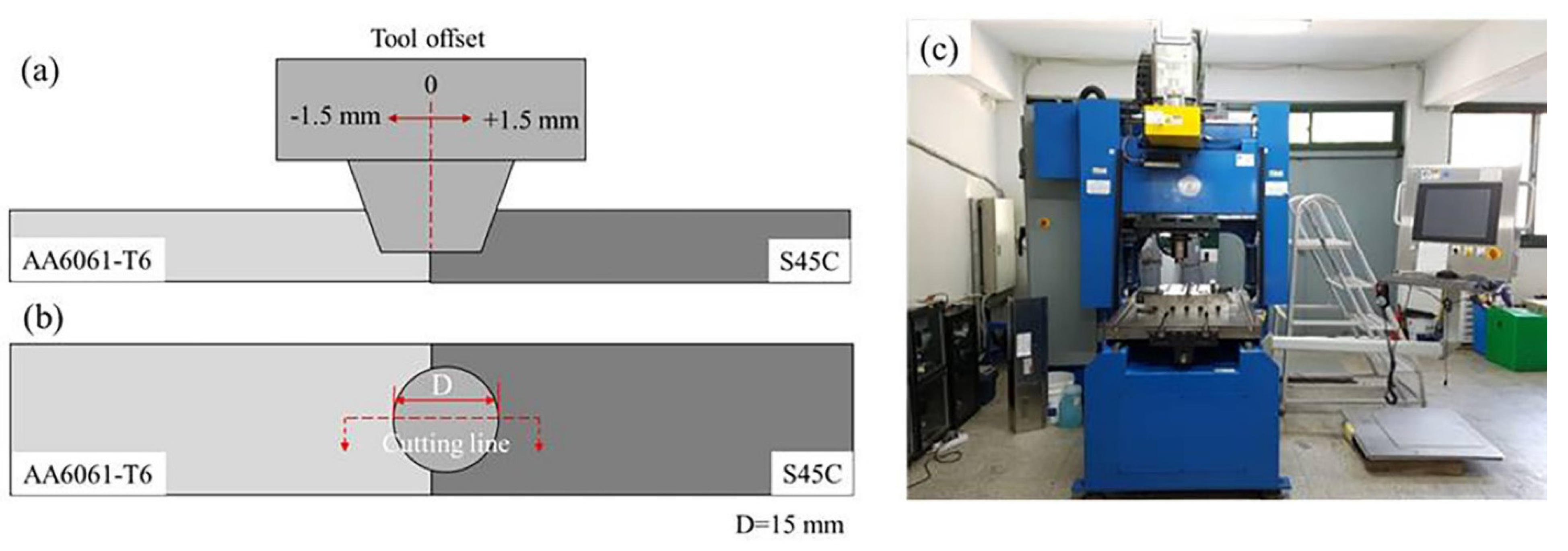
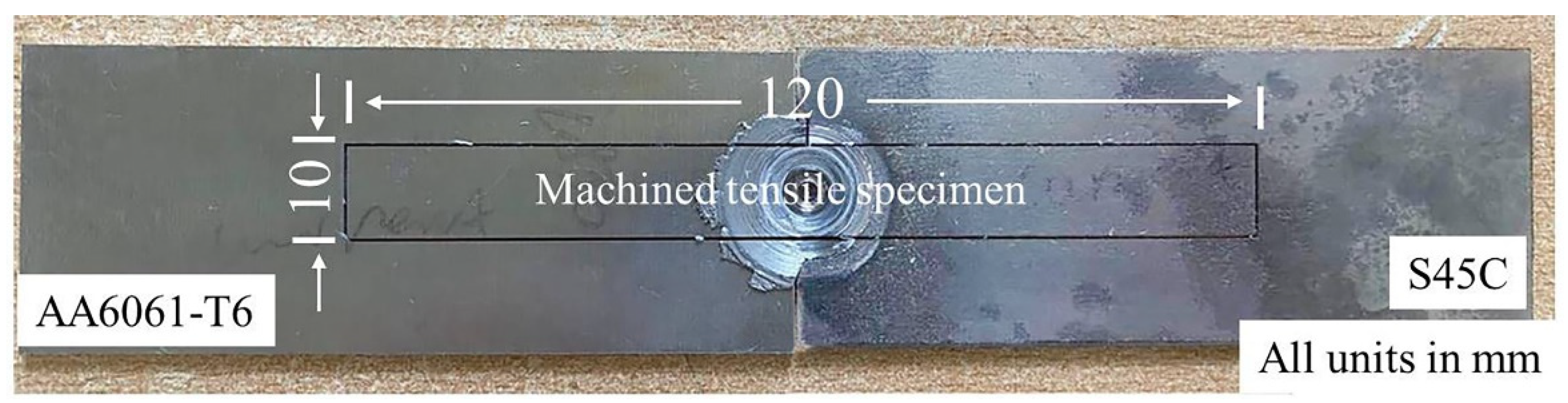
2. Experimental Set-Up

Commercially available S45C steel and 6061-T6 aluminum alloy (AA6061-T6) sheets were selected as the subject materials of the present study (chemical compositions in Table 1). These materials were cut to a cuboid shape with dimensions (in mm) of 100 (length) × 40 (width) × 2 (thickness) and were used as base materials (BMs) for the proposed butt FSSW.
Prior to joining, the BMs were carefully ground with 320-girt sandpaper to remove the oxide layer and thoroughly degreased with ethanol and acetone. A custom-made FSW machine (RM1A; Bond Technologies, Elkhart, IN, USA) was used to perform FSSW using a spark plasma sintered tungsten carbide (WC) tool (tool geometry in Table 2) on the designated materials in a butt configuration, as depicted in Figure 1a,b. As described in [29,30], alterations of the tool rotational speed and the tool offset significantly influence the material flow and formation of IMCs between the steel and aluminum alloy by varying the heat input and straining of materials during joining. Therefore, the FSSW was performed here by varying these two process parameters (in Table 3), while other parameters, including tool plunging rate, depth of penetration, and dwell time, were kept constant.
After FSSW, the quality of the joints was first visually inspected. Subsequently, the weld spots were cut through the joint center (red dotted line in Figure 1b) and were ground and polished for microstructural observation by optical microscopy (OM) (A1M Axio Imager; Carl Zeiss, Göttingen, Germany). The cross-sections of the joints were also examined using a field emission scanning electron microscope (FE-SEM) (SU-70; Hitachi, Tokyo, Japan) equipped with an energy dispersive spectrometer (EDS) (X-Max50; Horiba, Kyoto, Japan).
The friction stir spot welded specimens were commonly notched at both sides, as the welding was performed at the butt position. To avoid the stress concentration by the notch effect during quasistatic tensile testing to evaluate the mechanical properties of the joints, the friction stir spot welded joints were machined to the dimensions of (in mm) 120 (length) × 10 (width) × 2 (thickness) before tensile testing, as shown in Figure 2. The tensile strength of each joint was evaluated by using a universal testing machine with a constant displacement rate of 0.5 mm/min. Fracture surfaces of the tensile-tested joint specimens were investigated by SEM and were also detailed with EDS elemental analysis.

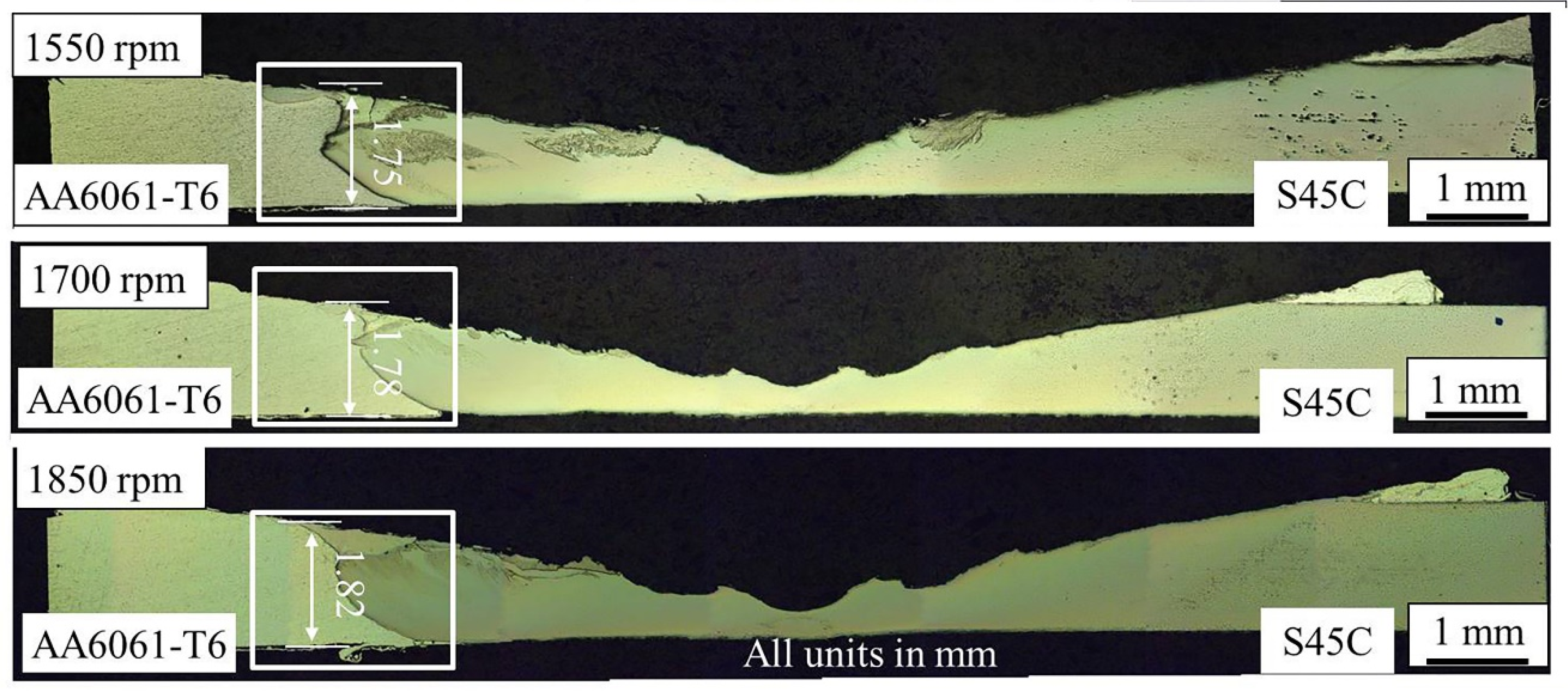
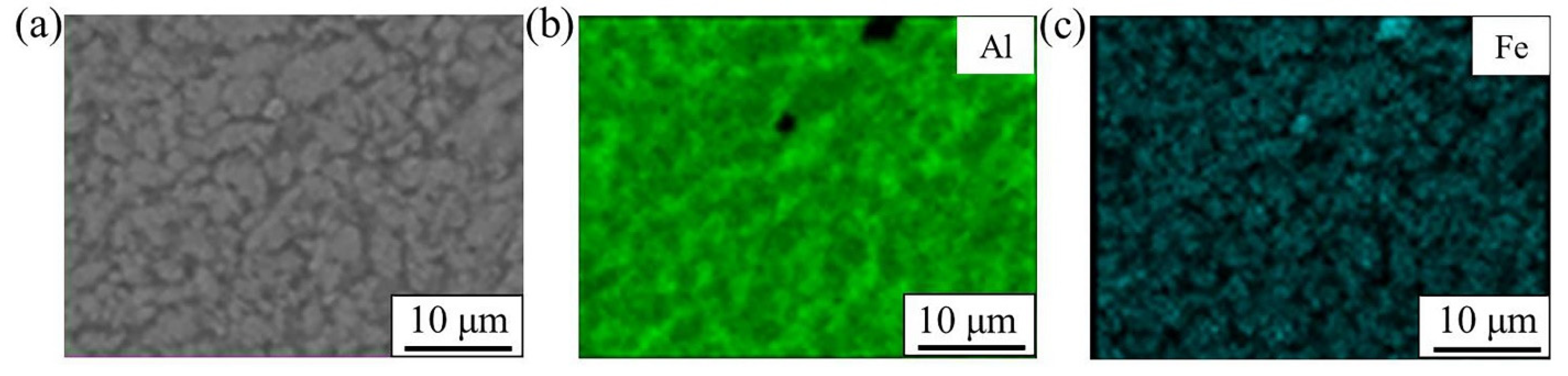
3. Results and Discussion

The appearance (top view) of the friction stir spot welded dissimilar joints of S45C steel and AA6061-T6 with different process parameters is shown in Figure 3. As summarized in Table 4, visual inspection of the joints confirmed that the tool position and tool rotational speed affected the shape and appearance of the weld surfaces.
When the tool was offset by 1.5 mm toward the AA6061-T6 side, evident defects, including surface cracks and partial fusion, were observed, as shown in Figure 3a–c. At relatively low tool rotational speeds (1400 and 1550 rpm), the AA6061-T6 was fused, which suggests that excessive heat was applied to the aluminum alloy during FSSW. Naturally, when increasing the tool rotational speed to 1700 rpm (Figure 3b), partial melting of the AA6061-T6 was aggravated.
Next, the tool position was shifted to the center of the weld between the S45C steel and the AA6061-T6 to diminish the excessive heating of the aluminum alloy. Unfortunately, the final results (Figure 3d–f) were similar to those obtained when the tool was offset to the AA6061-T6 side. Crack defects were still observed near the AA6061-T6/S45C joint interface. However, reducing the heat input to the aluminum alloy by shifting the tool position to the center of the weld certainly diminished the tendency of the AA6061-T6 to partially melt, as clearly shown in comparison to the results obtained with the relatively low tool rotational speed of 1400 rpm (Figure 3a,d). This suggests that properly distributing the heat input to the AA6061-T6 and the S45C steel by adjusting the tool offset can be helpful to prevent fusion defects in the joint.
Based on the trends observed in the experimental results shown in Figure 3a–f, the tool position was further offset (1.5 mm) to the S45C steel side. At the relatively low tool rotational speed of 1400 rpm (Figure 3g), obvious crack defects occurred at the interface between the S45C steel and the AA6061-T6 due to the insufficient heat input. However, with this tool offset position, it was encouraging that the quality of the surface morphology was improved (i.e., the crack defects disappeared) by increasing the tool rotational speeds to 1550, 1700, and 1850 rpm without the occurrence of fusion defects, as presented in Figure 3h–j. This shows that for the given material combination of S45C steel and the AA6061-T6, offsetting the tool to the steel side was beneficial to produce a defect-free joint as it did not exhibit surface cracks and flaws related to solidification. By offsetting the tool to the steel side, more heat input could be applied to the steel without inducing fusion defects in the aluminum side.
The friction stir spot welded joints without cracks or fusion defects on the surface (Figure 3h–j) were further subjected to microstructural analysis. No significant difference in the OM results (Figure 4) was observed among the cross-sections of the joints made with three different FSSW parameter combinations except that the FSSW joint developed crack defects during welding at 1550 rpm (Figure 5a), but no significant defects were observed at the rotational speeds of 1700 and 1850 rpm, as shown in Figure 5b,c, respectively.
The regions marked with the red triangles (M zones = mixed zones) in Figure 5a–c exhibit a slightly different color compared with the S45C steel and AA6061-T6. The typical SEM image (Figure 6a) and the results of the EDS area scan (Figure 6b,c) suggest that the M zones were a mixture of aluminum alloy (green color) and steel particles (blue color). This suggests that the plasticized aluminum alloy and numerous steel fragments peeled from the base metal were mechanically mixed into the M zone by the rotating tool. Further detailed characterization was carried out to observe the interdiffusion of Al and Fe between the AA6061-T6 and the S45C steel at the joint interface.
As shown in Figure 4 and Figure 5, an obvious boundary between the AA6061-T6 and the S45C steel was observed (except for the M zone at the top of the joint) for all three of the FSSW parameter combinations. The SEM results at the interface of the joints revealed a distinct layer with different colors between the S45C steel (bright region) and the AA6061-T6 (dark region) that was produced during welding at 1550 rpm (Figure 7a,b), 1700 rpm (Figure 8a,b), and 1850 rpm (Figure 9a,b).
The results of the EDS elemental line scan (Figure 7c, Figure 8c and Figure 9c) confirmed that the layers were composed of Al and Fe elements, which can be regarded as Al/Fe IMCs. Previous studies have suggested that atomic diffusion across the joint interface causes the formation of Al/Fe IMCs [16,24]. Further, in the present study, steel particles were observed on the Al side, as clearly shown in Figure 8b and Figure 9b. Those steel particles could have been the result of the detachment of steel fragments from the steel edges by high shear stress caused by the severe stirring motion of the tool at higher rotational speeds [31].
According to the Al–Fe phase diagram [32] and analysis of the EDS elemental compositions (in Table 5), the possible IMCs at the three different welding conditions can be deduced. As summarized in Table 5, the IMC layers in Figure 8b and Figure 9b may have consisted of FeAl (Fe-rich IMCs) and FeAl3 (Al-rich IMCs). In contrast, at the relatively lower rotational speed of 1550 rpm (Figure 7b), the IMC layer mainly included FeAl3 and Fe2Al5 (Al-rich IMCs). With the increase in tool rotational speed, more Fe-rich IMCs (FeAl) were formed at the joint interface, which is not detrimental to the joint strength compared with Al-rich IMCs [27].
The thickness of the IMC layer was approximated by the distribution of the major alloying elements across the interface through the EDS line scan, as shown in Figure 7c, Figure 8c and Figure 9c. When increasing the rotational speed from 1550 to 1850 rpm, a significant increase in the IMC layer thickness (from 2.7 to 4.6 μm) was observed. This indicates that a sufficient energy input or higher temperature can promote the diffusion of elements to the formation and growth of an Al/Fe IMC at the joint interface [24,33,34]. Still, in all of the FSSW conditions, the IMC layers formed at the joint interfaces were very thin.
Studies have shown that a thin IMC layer (less than 10 μm [10,12,35]) might not be detrimental to the mechanical properties of joints [11,24]. Here, the fractures in all of the friction stir spot welded joints occurred at the joining interface between the S45C steel and the AA6061-T6 after the tensile test (Figure 10b). As shown in the results of tensile tests (Figure 11), the maximum tensile strength of the friction stir spot welded joints (2830 ± 150 N) was obtained under the welding conditions of 1850 rpm. Note that the IMC layer of the friction stir spot welded joint created at the rotational speed of 1850 rpm was extremely thin (approximately 4.4 μm maximum thickness) compared with that of conventional fusion welding.
The IMC layer and the failure load simultaneously increased with the increase in the tool rotational speed, as presented in Figure 11. The correlation of the tensile strength of the joint and the thickness of the IMC layer in Figure 11 confirms that in a certain range of thickness, a thicker IMC layer seems to improve the strength of the joint [24,36]. Bozzi et al. [26] agreed with this view that an IMC layer may be necessary to improve the friction stir spot welded weld strength of aluminum alloy and steel joints. Here, fracture during tensile tests occurred along the interface of the S45C steel and the AA6061-T6 and crossed over the M zone of the steel and the aluminum for all the FSSW joints (Figure 12a). Figure 12b shows that the thickness of the remaining IMC layer on the AA6061-T6 side was approximately 2 μm; in contrast, the fracture surface on the S45C steel side showed almost no remaining IMC, as shown in Figure 12c. To summarize, the tensile fracture failure of friction stir spot welded joints mainly occurred in the top Al/Fe mixing zone and in the interface between the S45C steel and the IMC layer.

4. Conclusions

In the present work, FSSW of S45C steel and 6061-T6 aluminum alloy was conducted with different tool rotational speeds and tool positions. The experimental results showed that the friction stir spot welded butt joints of the dissimilar steel and the aluminum alloy were successfully fabricated by offsetting the tool by 1.5 mm toward the steel side. Microstructure analysis using SEM-EDS showed that an IMC layer was formed, and three possible IMCs (FeAl, FeAl3, and Fe2Al5) were identified at the joint interface. Increasing the tool rotational speed increased the thickness of the IMC layer. The results of point and line analysis suggested that a thicker IMC layer and Fe-rich IMCs seemed to be beneficial to improve the strength of the FSSW joints. The quasistatic tensile tests showed that fractures occurred along the joint interface and in the top Al/Fe mixing zone.

Author Contributions

Conceptualization, K.G. and S.-T.H.; methodology, K.G. and S.-T.H.; software, K.G.; validation, K.G., S.Z., S.-T.H., M.M., S.B. and H.S.; formal analysis, K.G. and S.-T.H.; investigation, K.G., S.Z. and S.-T.H.; resources, S.-T.H.; data curation, K.G., S.Z. and S.-T.H.; writing—original draft preparation, K.G.; writing—review and editing, S.-T.H.; supervision, S.-T.H.; project administration, S.-T.H.; funding acquisition, S.-T.H. All authors have read and agreed to the published version of the manuscript.

Funding

This research was funded by the 2021 research fund of the University of Ulsan.

Institutional Review Board Statement

Not applicable.

Informed Consent Statement

Not applicable.

Data Availability Statement

The raw/processed data required to reproduce these findings cannot be shared at this time as the data also form part of an ongoing study.

Acknowledgments

This work was supported by the 2021 research fund of the University of Ulsan.

Conflicts of Interest

The authors declare no conflict of interest.

References

  1. Cole, G.S.; Sherman, A.M. Light weight materials for automotive applications. Mater. Charact. 1995, 35, 3–9. [Google Scholar] [CrossRef]
  2. Schubert, E.; Klassen, M.; Zerner, I.; Walz, C.; Sepold, G. Light-weight structures produced by laser beam joining for future applications in automobile and aerospace industry. J. Mater. Process. Technol. 2001, 115, 2–8. [Google Scholar] [CrossRef]
  3. Hussein, S.A.; Tahir, A.S.M.; Hadzley, A.B. Characteristics of Aluminum-to-Steel Joint Made by Friction Stir Welding: A review. Mater. Today Commun. 2015, 5, 32–49. [Google Scholar] [CrossRef]
  4. Liu, X.; Lan, S.H.; Ni, J. Analysis of process parameters effects on friction stir welding of dissimilar aluminum alloy to advanced high strength steel. Mater. Des. 2014, 59, 50–62. [Google Scholar] [CrossRef]
  5. Qiu, R.; Shi, H.; Zhang, K.; Tu, Y.; Iwamoto, C.; Satonaka, S. Interfacial characterization of joint between mild steel and aluminum alloy welded by resistance spot welding. Mater. Charact. 2010, 61, 684–688. [Google Scholar] [CrossRef]
  6. Lin, S.B.; Song, J.L.; Ma, G.C.; Yang, C.L. Dissimilar metals TIG welding-brazing of aluminium alloy to galvanized steel. Front. Mater. Sci. China 2009, 3, 78–83. [Google Scholar] [CrossRef]
  7. Chen, H.C.; Pinkerton, A.J.; Li, L.; Liu, Z.; Mistry, A.T. Gap-free fibre laser welding of Zn-coated steel on Al alloy for light-weight automotive applications. Mater. Des. 2011, 32, 495–504. [Google Scholar] [CrossRef]
  8. Peyre, P.; Sierra, G.; Deschaux-Beaume, F.; Stuart, D.; Fras, G. Generation of aluminium-steel joints with laser-induced reactive wetting. Mater. Sci. Eng. A 2007, 444, 327–338. [Google Scholar] [CrossRef]
  9. Mathieu, A.; Shabadi, R.; Deschamps, A.; Suery, M.; Mattei, S.; Grevey, D.; Cicala, E. Dissimilar material joining using laser (aluminum to steel using zinc-based filler wire). Opt. Laser Technol. 2007, 39, 652–661. [Google Scholar] [CrossRef]
  10. Arghavani, M.R.; Movahedi, M.; Kokabi, A.H. Role of zinc layer in resistance spot welding of aluminium to steel. Mater. Des. 2016, 102, 106–114. [Google Scholar] [CrossRef]
  11. Chen, N.; Wang, H.P.; Carlson, B.E.; Sigler, D.R.; Wang, M. Fracture mechanisms of Al/steel resistance spot welds in lap shear test. J. Mater. Process Technol. 2017, 243, 347–354. [Google Scholar] [CrossRef]
  12. Miyamoto, K.; Nakagawa, S.; Sugi, C.; Sakurai, H.; Hirose, A. Dissimilar joining of aluminum alloy and steel by resistance spot welding. SAE Int. J. Mater. Manuf. 2009, 2, 58–67. [Google Scholar] [CrossRef]
  13. Mustafa, A.; Bilge, D. An investigation of mechanical and metallurgical properties of explosive welded aluminum-dual phase steel. Mater. Lett. 2008, 62, 4158–4160. [Google Scholar]
  14. Xue, J.Y.; Li, Y.X.; Chen, H.; Zhu, Z.T. Wettability, microstructure and properties of 6061 aluminum alloy/304 stainless steel butt joint achieved by laser-metal inert-gas hybrid welding-brazing. Trans. Nonferrous Met. Soc. China 2018, 28, 1938–1946. [Google Scholar] [CrossRef]
  15. Meshram, S.D.; Mohandas, T.; Reddy, G.M. Friction welding of dissimilar pure metals. J. Mater. Process. Technol. 2007, 184, 330–337. [Google Scholar] [CrossRef]
  16. Zhang, S.; Gao, K.; Hong, S.-T.; Ahn, H.; Choi, Y.; Lee, S.; Han, H.N. Electrically assisted solid state lap joining of dissimilar steel S45C and aluminum 6061-T6 alloy. J. Mater. Res. Technol. 2021, 12, 271–282. [Google Scholar] [CrossRef]
  17. Findik, F. Recent developments in explosive welding. Mater. Des. 2011, 32, 1081–1193. [Google Scholar] [CrossRef]
  18. Jiang, H.; Liao, Y.; Gao, S.; Li, G.; Cui, J. Comparative study on joining quality of electromagnetic driven self-piecing riveting, adhesive and hybrid joints for Al/steel structure. Thin-Walled Struct. 2021, 164, 107903. [Google Scholar] [CrossRef]
  19. Thomas, W.M.; Nicholas, E.D.; Needham, J.C.; Murch, M.G.; Temple-Smith, P.; Dawes, C.J. Friction Stir Butt Welding. International Patent Application No. PCT/GB92/02203 and GB Patent Application No. 9125978.8, 6 December 1991. [Google Scholar]
  20. Rai, R.; De, A.; Bhadeshia, H.K.D.H.; DebRoy, T. Review: Friction stir welding tools. Sci. Technol. Weld Join. 2011, 16, 325–342. [Google Scholar] [CrossRef]
  21. Wang, L.; Huang, Y.X. Friction stir welding of dissimilar aluminum alloys and steels: A review. Int. J. Adv. Manuf. Technol. 2018, 99, 1781–1811. [Google Scholar]
  22. Watanabe, T.; Takayama, H.; Yanagisawa, A. Joining of aluminum alloy to steel by friction stir welding. J. Mater. Process. Technol. 2006, 178, 342–349. [Google Scholar] [CrossRef]
  23. Kimapong, K.; Watanabe, T. Lap Joint of A5083 aluminum alloy and SS400 steel by friction stir welding. Mater. Trans. 2005, 46, 835–841. [Google Scholar] [CrossRef] [Green Version]
  24. Fereiduni, E.; Movahedi, M.; Kokabi, A.H. Aluminum/steel joints made by an alternative friction stir spot welding process. J. Mater. Process. Technol. 2015, 224, 1–10. [Google Scholar] [CrossRef]
  25. Coelho, R.S.; Kostka, A.; Dos Santos, J.F.; Kaysser-Pyzalla, A. Friction-stir dissimilar welding of aluminum alloy to high strength steels: Mechanical properties and their relation to microstructure. Mater. Sci. Eng. A 2012, 556, 175–183. [Google Scholar] [CrossRef]
  26. Bozzi, S.; Helbert-Etter, A.L.; Baudin, T.; Criqui, B.; Kerbiguet, J.G. Intermetallic compounds in Al 6016/IF-steel friction stir spot welds. Mater. Sci. Eng. A 2010, 527, 4505–4509. [Google Scholar] [CrossRef]
  27. Pourali, M.; Abdollah-zadeh, A.; Saeid, T.; Kargar, F. Influence of welding parameters on intermetallic compounds formation in dissimilar steel/aluminum friction stir welds. J. Alloys Compd. 2017, 715, 1–8. [Google Scholar] [CrossRef]
  28. Kaushik, P.; Dwivedi, D.K. Effect of tool geometry in dissimilar Al-steel friction stir welding. J. Manuf. Process. 2021, 68, 198–208. [Google Scholar] [CrossRef]
  29. Jeon, C.S.; Hong, S.-T.; Kwon, Y.J.; Cho, H.H.; Han, H.N. Material properties of friction stir spot welded joints of dissimilar aluminum alloys. Trans. Nonferrous Met. Soc. China. 2012, 22, s605–s613. [Google Scholar] [CrossRef]
  30. Yuan, W.; Mishra, R.S.; Webb, S.; Chen, Y.L.; Carlson, B.; Herling, D.R.; Grant, G.J. Effect of tool design and process parameters on properties of Al alloy 6016 friction stir spot welds. J. Mater. Process. Technol. 2011, 211, 972–977. [Google Scholar] [CrossRef]
  31. Zandsalimi, S.; Heidarzadeh, A.; Saeid, T. Dissimilar friction-stir welding of 430 stainless steel and 6061 aluminum alloy: Microstructure and mechanical properties of the joints. Proc. Inst. Mech. Eng. Part L J. Mater. Des. Appl. 2019, 233, 1791–1801. [Google Scholar] [CrossRef]
  32. Sina, H.; Corneliusson, J.; Turba, K.; Iyengar, S. A study on the formation of iron aluminide (FeAl) from elemental powders. J. Alloys Compds. 2015, 636, 261–269. [Google Scholar] [CrossRef]
  33. Sundman, B.; Ohnuma, I.; Dupin, N.; Kattner, U.R.; Fries, S.G. An assessment of the entire Al-Fe system including D03 ordering. Acta Mater. 2009, 57, 2896–2908. [Google Scholar] [CrossRef]
  34. Chmielewski, T.; Marcin Chmielewski, O.; Piątkowska, A.; Grabias, A.; Beata Skowrońska, O.; Siwek, P. Phase Structure Evolution of the Fe-Al Arc-Sprayed Coating Stimulated by Annealing. Materials 2021, 14, 3210. [Google Scholar] [CrossRef] [PubMed]
  35. Tanaka, T.; Nezu, M.; Uchida, S.; Hirata, T. Mechanism of intermetallic compound formation during the dissimilar friction stir welding of aluminum and steel. J. Mater. Sci. 2020, 55, 3064–3072. [Google Scholar] [CrossRef]
  36. Tanaka, T.; Hirata, T.; Shinomiya, N.; Shirakawa, N. Analysis of material flow in the sheet forming of friction-stir welds on alloys of mild steel and aluminum. J. Mater. Process. Technol. 2015, 226, 115–124. [Google Scholar] [CrossRef]
Figure 1. Schematics of specimen configuration: (a) side and (b) top views; (c) FSSW machine.
Metals 11 01252 g001
Figure 2. Dimensions for a tensile specimen from a butt FSSW joint.
Metals 11 01252 g002
Figure 3. FSSW joints: (ac) tool offset 1.5 mm toward the AA6061-T6 side, (df) no offset, and (gj) tool offset 1.5 mm toward the S45C steel side.
Metals 11 01252 g003
Figure 4. Optical macrographs of the weld cross-sections at three different tool rotational speeds (tool offset 1.5 mm toward the S45C steel side).
Metals 11 01252 g004
Figure 5. Magnified views of the regions marked by a white rectangle in Figure 4: (a) 1550 rpm, (b) 1700 rpm, and (c) 1850 rpm.
Metals 11 01252 g005
Figure 6. From Figure 5c: (a) SEM image of M zone, (b) Al distribution, and (c) Fe distribution.
Metals 11 01252 g006
Figure 7. (a) SEM image of the region marked by a red rectangle in Figure 5a, (b) magnified SEM image of the joint interface (a white rectangle in (a)), and (c) elemental line scan across the joint interface.
Metals 11 01252 g007
Figure 8. (a) SEM image of the region marked by a red rectangle in Figure 5b, (b) magnified SEM image of the joint interface (a white rectangle in (a)), and (c) elemental line scan across the joint interface.
Metals 11 01252 g008
Figure 9. (a) SEM image of the region marked by a red rectangle in Figure 5c, (b) magnified SEM image of the joint interface (a white rectangle in (a)), and (c) elemental line scan across the joint interface.
Metals 11 01252 g009
Figure 10. (a) Machined joint specimens and (b) tensile fractured specimens.
Metals 11 01252 g010
Figure 11. Thickness of IMC and joint failure load as functions of tool rotational speed.
Metals 11 01252 g011
Figure 12. (a) A cross-sectional image of FSSW joints after tensile test (tool rotational speed of 1550 rpm); SEM images and elemental line scans on (b) the AA6061-T6 side and (c) the S45C side.
Metals 11 01252 g012
Table 1. Chemical compositions and mechanical properties of AA6061-T6 and S45C steel.
Chemical Composition (wt%)
MaterialsCPSAlSiMnFeMgCuCrZn
S45C0.040.010.0030.020.0020.15Bal.----
AA6061-T6---Bal.0.60.110.40.90.230.170.04
Mechanical properties
MaterialsYield stress (MPa)Tensile strength (MPa)Elongation at fracture (%)
S45C34356916
AA6061-T627631017
Table 2. Geometry of the FSW tool.
Tool GeometryDimension
Shoulder diameter (mm)14.3 mm
Pin height (mm)0.6 mm
Pin diameter (mm)2.0 mm
Shoulder typeConvex scrolled shoulder
Table 3. Process parameters for FSSW of AA6061-T6 and S45C steel.
No.Penetration Depth
(mm)
Dwell Time
(s)
Temperature
Condition (°C)
Tool Plunging Rate
(mm/min)
Tool OffsetRotational Speed
(rpm)
11.73Room temperature
(~25)
10−1.5 mm1400
21550
31700
401400
51550
61700
7+1.5 mm1400
81550
91700
101850
Table 4. Observations of the weld surfaces under different parameter combinations.
No.Tool OffsetTool Rotational Speed (rpm)Weld Quality
11.5 mm
toward Al side
1400Defective and melted
21550Melted
31700Melted
401400Defective and melted
51550Defective and melted
61700Melted
7+1.5 mm
toward steel side
1400Defective
81550Good
91700Good
101850Good
Table 5. Chemical compositions of IMC and possible phases in Figure 7, Figure 8 and Figure 9.
Tool Rotational Speed
(rpm)
LocationComposition (at.%)Possible
Phases
IMC Layer Thickness (μm) *
AlFeAl/Fe Ratio
1550P174.4625.543.11FeAl32.7 (± 0.8)
P269.6829.462.36Fe2Al5
1700P172.7527.252.70FeAl33.3 (± 1.0)
P250.2849.72~1FeAl
P348.4351.57~1FeAl
1850P172.9027.102.70FeAl34.1 (± 1.1)
P249.7550.25~1FeAl
P346.2553.75~1FeAl
* Average value at three different locations.
Publisher’s Note: MDPI stays neutral with regard to jurisdictional claims in published maps and institutional affiliations.

