Article

Numerical Simulation and Experimental Investigation on 2205 Duplex Stainless Steel K-TIG Welded Joint

1
School of Mechanical and Transportation Engineering, Guangxi University of Science and Technology, Liuzhou 545006, China
2
Guangxi Zhuang Autonomous Region Tobacco Company Liuzhou Tobacco Company, Liuzhou 545006, China
*
Author to whom correspondence should be addressed.
Metals 2021, 11(8), 1323; https://doi.org/10.3390/met11081323
Submission received: 27 July 2021 / Revised: 19 August 2021 / Accepted: 20 August 2021 / Published: 21 August 2021
(This article belongs to the Section Metal Casting, Forming and Heat Treatment)

Abstract

:
In this paper, 8 mm thickness 2205 duplex stainless steel (DSS) plates were successfully welded using keyhole tungsten inert gas welding (K-TIG) welding, and numerical simulations were performed applying the finite element method. Three models of combined heat source were adopted to verify accuracy of experiment. The welding process under different welding speeds were simulated, and the temperature field, molten pool shape, and thermal cycle curve were calculated. The welding simulation results show that a combined model consisting of the ellipsoid heat source and the conical heat source is more suitable for K-TIG welding. The results of the microstructure analysis of the welded joint showed that when the welding speed was increased from 280 mm/min to 340 mm/min, the austenite content and the ferrite and austenite grain size decreased. The evolution laws of welded joint morphologies, microstructure and grain sizes under different welding speed conditions were consistent with the analysis results of simulated molten pool morphologies, temperature field distributions and thermal cycle curves. It is proved that this kind of simulation method can effectively simulate the K-TIG welding process and ensure the welding quality, which is a guide for industrial applications.

1. Introduction

Due to high strength resistance and good corrosion resistance, a strong tendency to use DSS (duplex stainless steel) as structural materials in industry has been increased. Welding is an important technical method to connect DSS, so the weldability of DSS is very important in industry production. Ferrite in DSS is prone to hydrogen embrittlement and hydrogen-induced cracking, and Wierczyńska et al. [1] proved that the presence of hydrogen in the welded joints of DSS affected the cracking mechanism. Nitrogen content in duplex steel can affect austenite production in welded joints. Varbai et al. [2] found that excessive heat input can make significant nitrogen loss, causing the austenite content decreases, which causes the strength and toughness of the joints to decrease. However, different welding methods will affect the hydrogen content and nitrogen content of DSS welded joints so that it is very important to select a suitable welding method to ensure the quality of DSS welded joints. In the traditional welding of medium and thick plates, multi-pass welding is often used, but this method have a large heat-affected zone (HAZ) due to large heat input, which causes the precipitation of coarse grains and harmful phases. Keyhole tungsten inert gas (K-TIG) welding is a keyhole type TIG welding method, which has high efficiency and low cost. It has been utilized in medium-thick plates welding [3,4,5]. These advantages of K-TIG welding in welding medium-thick plates have aroused the interest of scholars and have carried out research on it. Feng et al. [6] studied K-TIG welding of 316L stainless steel with a thickness of 10 mm, and successfully obtained a well-formed single-sided welded double-sided weld bead. Fan et al. [7] tried to perform K-TIG welding on low-alloy steel Q345 with high thermal conductivity and used the forced forming method of circulating cooling water to obtain single-sided welding and double-sided forming, but failed to obtain a welded joint that meets the performance requirements. Cui et al. [8] conducted K-TIG full penetration keyhole welding experiments on 4 mm 304 stainless steel, and realized stable keyhole welding, but there was a disadvantage that the process window was too narrow. But above scholars did not study the influence of the temperature change process on the microstructure of the welded joint. For having a deeper understanding of the influence mechanism of K-TIG welding on the microstructure of the welded joints, it is necessary to study the evolution of the microstructure and grains of the welded joints base on the temperature change and temperature distribution during the welding process. At present, affected by the experimental conditions, the temperature change and temperature distribution in the molten pool are difficult to obtain through experimental methods, which prevents people from exploring the influence of temperature during welding process on the microstructure and grain of the welded joints.
Nowadays, the finite element simulation is the most suitable method to predict the weld pool shape, thermal distortion, residual stress, and metallurgical change. But complex phenomena in actual K-TIG welding makes the simulation of the welding process be a complicated problem [9]. Chen et al. [10] established a three-dimensional numerical model to study the change of keyhole with temperature and the evolution of fluid flow in the molten pool, and discovered how the keyhole affects the heat transfer and mechanical energy of the molten pool. Han et al. [11] used three forms of combined heat sources to numerically simulate the temperature field and the stress field of the Q345 low alloy K-TIG welding process, and found that the plate thickness, gap, and welding speeds can affect the deformation and stress after K-TIG welding. Zhang et al. [12] used FLUENT software to research the arc characteristics of K-TIG welding. At present, there are few studies on the K-TIG welding simulation of DSS, and the welding thermal cycle has a great influence on the microstructure and mechanical properties of the welded joint. Combining the welding numerical simulation results and the microstructure of the welded joint, the influence of welding speed on the microstructure of the welded joint was systematically studied, which can guide the application of DSS K-TIG welding in industry.

2. Materials and Methods

2.1. Experimental Procedure

The K-TIG welding torch was controlled by a six-axis KUKA robot (KUKA, Augsburg, Germany), which was shown in Figure 1. The cooling water was used to cool the tungsten welding torch, and pure argon was used as the shielding gas with a flow rate of 20 L/min, which imposed to the back side of workpieces. Lanthanum tungsten was selected as the tungsten electrode, and the electrode diameter was 6.4 mm. The welding parameters were shown in Table 1. After welding, the cross-section of the welded joints perpendicular to the welding direction were cut and polished. The Beraha etchant (30 mL H2O + 60 mL HCL + 1g K2S2O5) was used to corrode the welded joints for 5 s. The morphologies of the welded joints were observed after flushing and drying, and conducted weld visual test (VT) on the weld morphologies. Based on ASTM E1245-03(2016) standard, the austenite content of the weld metal zone (WMZ) was measured using Image Pro software [13]. The grain size of ferrite and austenite were examined by electron backscatter diffraction (EBSD) technique.

2.2. Materials

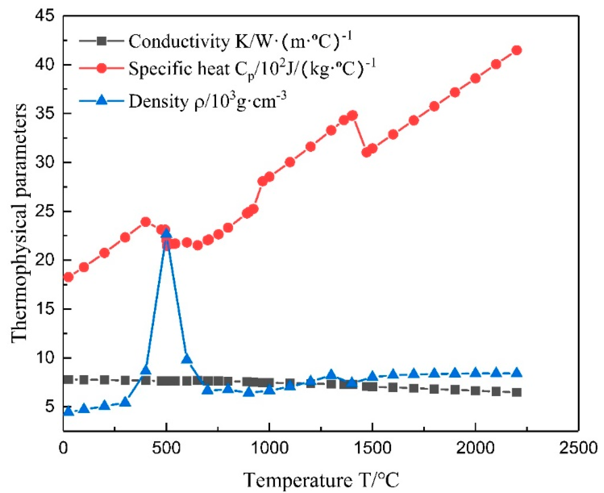
The base metal (BM) used in this research are 2205 DSS plates with dimensions of 300 mm × 100 mm × 8 mm. The chemical compositions of 2205 DSS using in this research are given in Table 2. According to the related principles of thermodynamics, the JMATPRO software was used to calculate the thermophysical performance parameters of 2205 DSS with temperature changes, including density, specific heat capacity, and thermal conductivity, as shown in Figure 2. However, the simulation results not only depend on the properties of the material, but also closely related to convection and radiation, and these properties can change with temperature. For the convenience of calculation, the effect of convection and radiation on the workpiece was replaced by the comprehensive heat transfer coefficient in simulation. In addition, the melting point of 2205 DSS is about 1470 °C.

3. Numerical Simulation

3.1. Modeling

3.1.1. Basic Formulas of Temperature Distribution Calculations

Numerical simulations of temperature distribution were calculated on the basis of Fourier’s differential equation. It is necessary to obtain the values of the heat conduction coefficient, specific heat, and density depending on the temperature to perform Equation (1) [14,15]:
T t = λ c ρ ( 2 T x 2 + 2 T y 2 + 2 T z 2 ) = α 2 T
where T is the temperature, t is time, x, y, and z refer to the point coordinates, α is the thermal diffusivity coefficient, λ is the heat conductivity coefficient, c is specific heat, and ρ is mass density.
In the K-TIG welding process, the workpieces exchange heat energy through convection and radiation. Therefore, the Newton’s law and Stefan-Boltzmann’s law were adopted to calculate the heat losses (2) [16,17,18,19]:
q = ε σ ( T r 4     T 4 )   +   h ( T r T )
where σ is Stefan-Boltzmann constant, and ε represents the emissivity, h represents the convection heat transfer coefficient, Tr and T represent the temperature of two contacting objects, −q represents the heat loss.

3.1.2. Heat Source Model

K-TIG welding is a keyhole welding method that achieves large penetration depth. It is mainly based on the traditional TIG welding method and uses a larger current to generate an arc with high energy, high stiffness, and strong penetration to achieve welding. However, a single heat source cannot accurately describe the heat distribution of high energy welding process on the workpiece. Therefore, three types of combined heat source models were used to simulate the K-TIG welding process in this research, as shown in Figure 3. The combined heat source models as follow:
  • The ellipsoid + the cylindrical heat source model
  • The ellipsoid + the conical heat source model
  • The ellipsoid + the columnar peak increasing heat source model

3.1.3. Mesh Model

The size of the actual welding workpiece was too large so that the mesh division was too large, which will lead to insufficient calculation accuracy. To reduce calculation amount and meet the accuracy requirements at the same time, a simplified finite element model was built, which composed two model of plates with dimensions of 100 mm × 80 mm × 8 mm. The grid size of welded zones, which determines the accuracy of simulation, was decided to 1 mm × 1 mm × 1 mm. The area away from the weld has little effect on the results of the temperature field simulation, so an incremental mesh was used to increase the size of the grid cell in the non-welded area to further reduce the calculation time. After meshing the whole model, model was divided into mesh elements with nodes
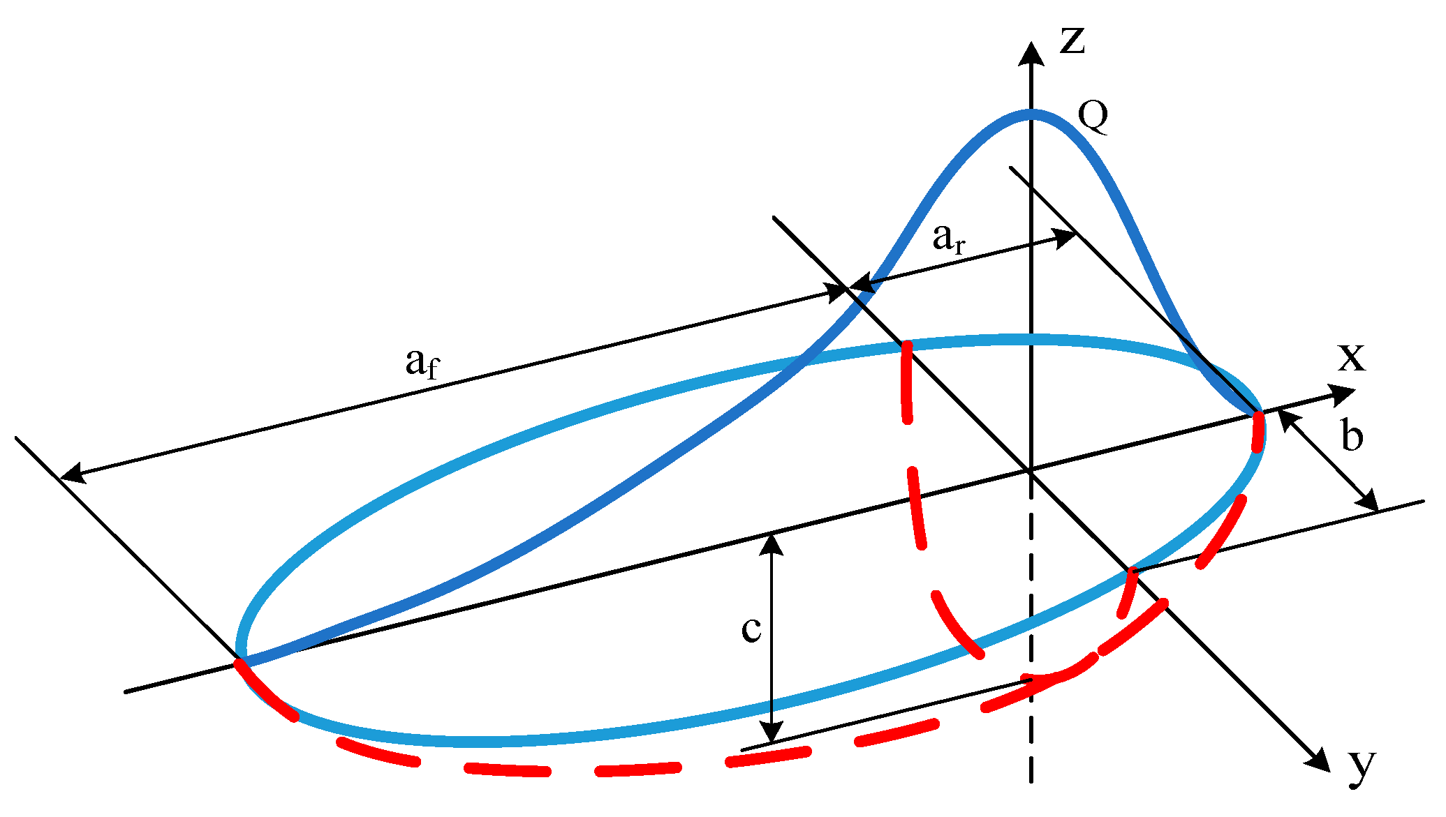
The results of simulation are obtained by the following heat source formula and parameters as shown in Table 3. The double ellipsoid heat source model was defined to power distribution in two different ellipsoids, which were in the front quadrant qf and rear quadrant qr [19], as described in Figure 4.
Let the energy fraction of the front part of the ellipsoid be f1 and that of the rear part be f2, and f1 plus f2 equals two. For the front part of the ellipsoid, the equation was described (3):
q ( f ) = 6 3 f 1 Q π 3 2 a f bc exp ( 3 ( ( x a f ) 2 + ( y b ) 2 + ( z c ) 2 ) ) .
And for the rear part of ellipsoid, the equation was described (4):
q ( r ) = 6 3 f 2 Q π 3 2 a r bc exp ( 3 ( ( x a r ) 2 + ( y b ) 2 + ( z c ) 2 ) )
where q(f) and q(r) are the volumetric heat flux density in front and rear part of the model, respectively, Q is the total introduced power, af, ar, b and c are respectively the length, width, depth of the front and the rear part of the estimated molten pool.
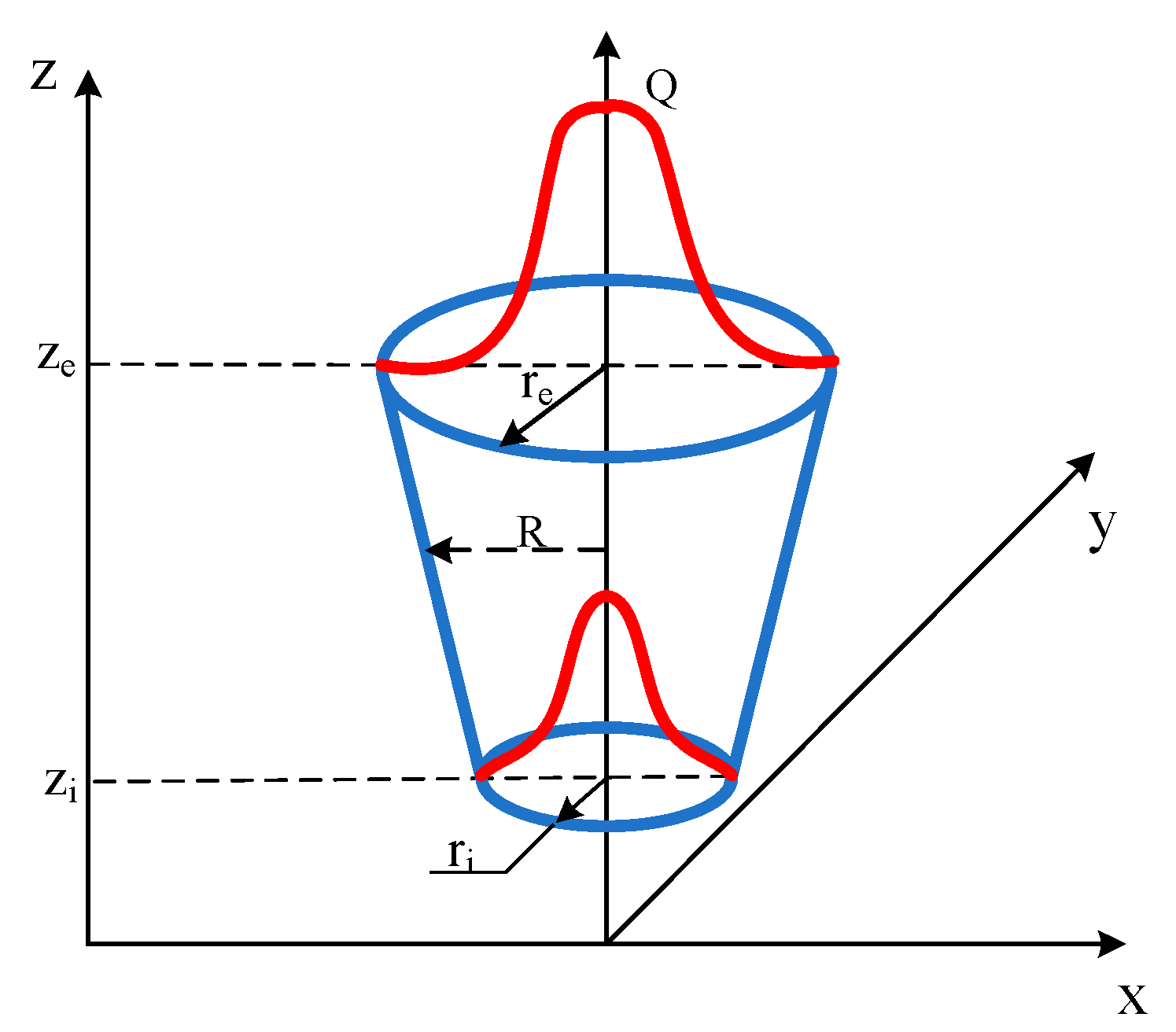
The Gaussian cone heat source model was described in Figure 5.
The model of conical heat source can be expressed by mathematical Formulas (5) and (6) [12,20];
q ( r ,   z ) = 9 Qe 3 π H ( e 3 1 ) ( r e 2 + r e r i + r i 2 ) exp ( 3 r 2 R 2 )
R = r e ( r e r i ) ( z e z ) z e z i
where Q is the maximum value of volumetric heat flux density, re and ri are respectively the upper and lower cone radius dimensions parameters, ze and zi are the cone height parameters.
And the formula for cylindrical heat source was described as (7), and the formula for increasing heat source was described as (8).
q = 3 Q π HR 2 exp ( 3 r 2 R 2 )
where Q is the whole power of welding, H represents the wording depth of the heat source, R is the effective thermal radius of heat source.
q = 6 Q ( m ( Z ) + R ) π HR 2 ( mH + 2 R ) exp ( 3 r 2 R 2 )
where Q is the whole power of welding, H represents the wording depth of the heat source, R is the effective thermal radius of heat source, m is the increasing factor.

4. Results and Discussion

4.1. Weld Morphology

The weld morphologies under different welding speeds were shown in Figure 6. It can be seen that when the welding speed were 280–340 mm/min, the front of the K-TIG welds were bright silver. The K-TIG welds were continuous and the width of the welds were relatively uniform. No obvious pores, cracks and other welding defects were found on the surface of the welds. When the welding speed was 360 mm/min, the back of the workpiece was not completely penetrated.

4.2. Simulation and Verification

Figure 7 shows the cross-section of the welded joint obtained by numerical simulation of three combined heat sources models. According to the contrast of the simulated cross-section and the actual pool profile, it can be found from Figure 7a that the lower part of the simulated cross-section was cylindrical, which cannot accurately show the conical shape of the lower molten pool obtained by K-TIG welding. According to Figure 7c, it was found that the molten pool presents an inverted cone shape at the bottom, which did not match the actual situation. Therefore, it was concluded that the results of the first model and the third model simulation did not get satisfied shape of molten pool, which cannot accord with profile of actual weld joint. But it was seen that the second combined heat source model not only penetrates completely the workpiece in numerical simulation but also show hourglass shape of simulated cross-section, separately exhibited in Figure 7b. Meanwhile the shape of cross-section was accord with experimental cross-section. It can be concluded that a combined heat source model form using an ellipsoid heat source as the upper part and a cylindrical heat source as the lower part was more suitable in numerical simulation of K-TIG welding.

4.3. Results of Numerical Simulation

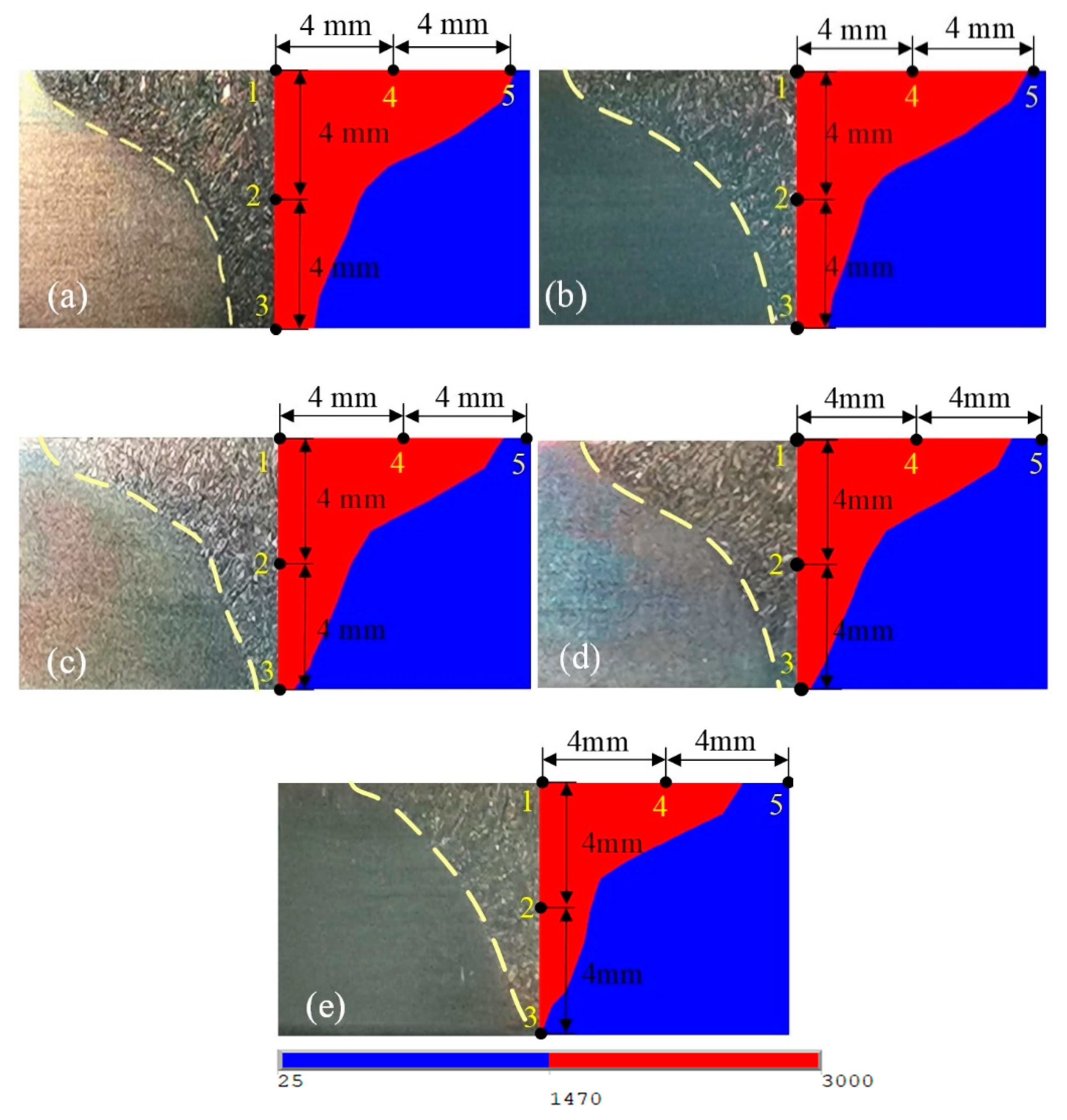
Figure 8 was the cross-section of the simulated weld pool and the actual welded joint at different welding speeds. When the welding speeds were 280–340 mm/min, the molten pool penetrates the entire workpieces, and the actual weld morphologies were close to the simulated molten pool morphologies. When the welding speed was 360 mm/min, the workpiece was not completely penetrated in the cross-section of the simulated weld pool, which was consistent with the test result. However, the cross sections of the simulated weld pool and actual welds were obviously different. In the cross-section of the simulated weld pool, the fusion line was composed of two curves with different curvatures. In the cross-section of the actual weld, the fusion line was composed of an approximate straight line. The main reason was that when the welding speed was 360 mm/min, the welding speed was relatively fast, the workpieces were not completely penetrated, and the keyhole effect did not appear during the K-TIG welding process. Therefore, the heat source model used in K-TIG welding was not suitable for this speed. When the welding speed was 360 mm/min, the workpieces were not completely penetrated, and there are welding defects in the welded joint. Therefore, the microstructure of welded joint under this welding speed was no longer analyzed.
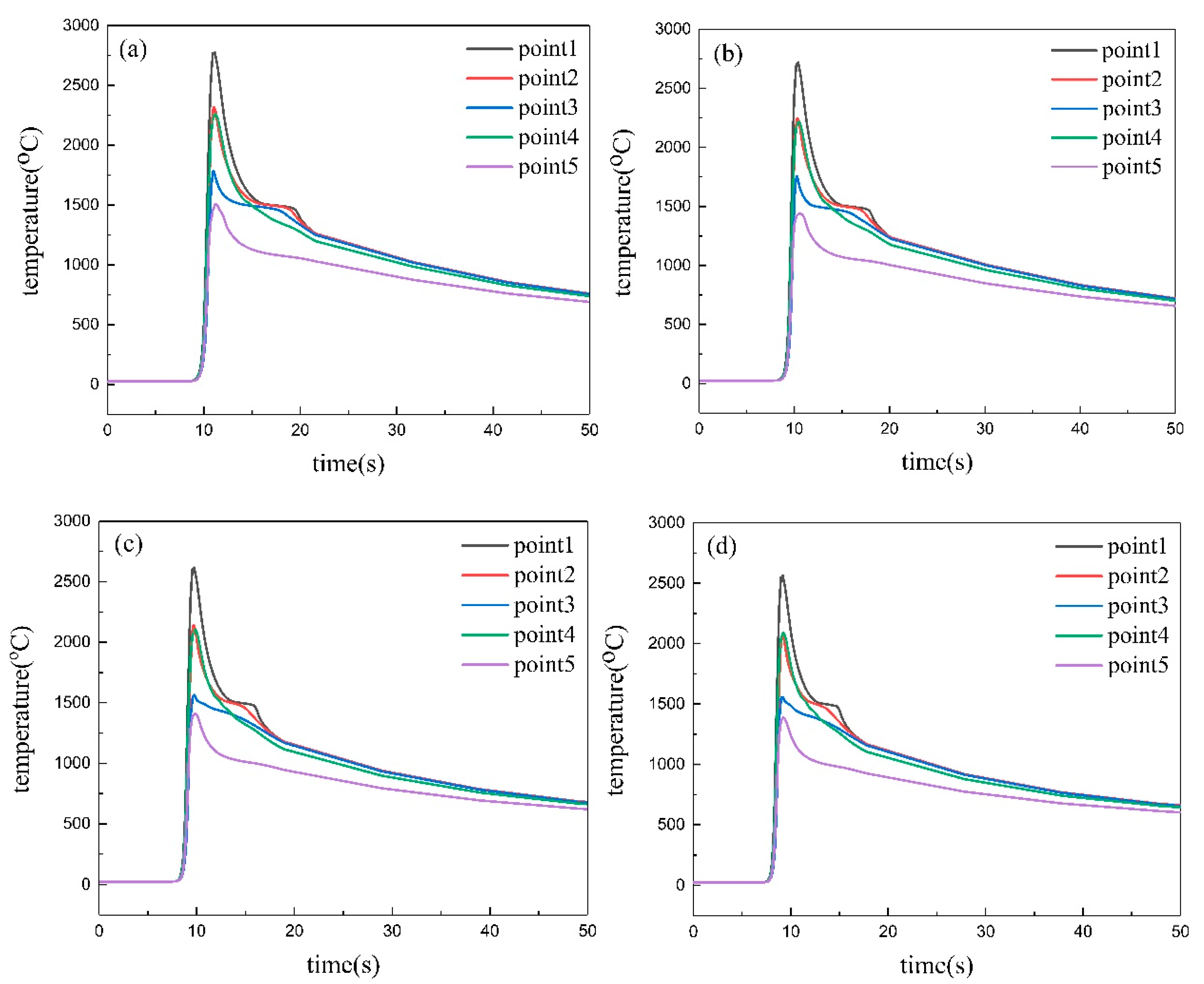
To have a deeper understanding of the characteristics of temperature changes, points 1~5 on the simulated cross-section in Figure 8 were selected to analyze the temperature distribution and change characteristics during K-TIG welding. The thermal cycle curve at these points were shown in Figure 9. When the arc touches the surface of the workpiece, the slope of the temperature history curve rises sharply. After reaching the peak temperature, the temperature drops immediately due to air convection heat transfer. At the same time, the peak temperatures of these vertical points were higher than the melting point of 2205 DDS, which can ensure that the workpieces were completely melted.
It can be seen from Figure 9 that under the same set of welding parameters, these points reach the peak temperature almost at the same time, and the peak temperature of points gradually decreases as the distance from the welding center increases. This was because that with the distance from central heat source increasing, the heat power transfer would weaken. Meanwhile points were located at different locations, resulting in different heat input and cooling environment, so that the cooling rate and heating rate of different points were different. In Figure 9, the slope of the curves before the peak temperature were greater than the slope of the curves after the peak temperature. It was shows that during the K-TIG welding process, the melting rate of metal was faster than the cooling rate. The cooling rate was a crucial factor that affects the microstructure and grain size of the weld, faster cooling rate was conducive to grain refinement. It is shown in Figure 9 that the cooling rates of other points were lower than point 1 that indicated the grain sizes of weld center were smaller than other areas of the weld. The cooling rate at the same point increased as the welding speed increased. It can be inferred that the grain size of WM was gradually decreased as the welding speed increased.

4.4. Microstructure

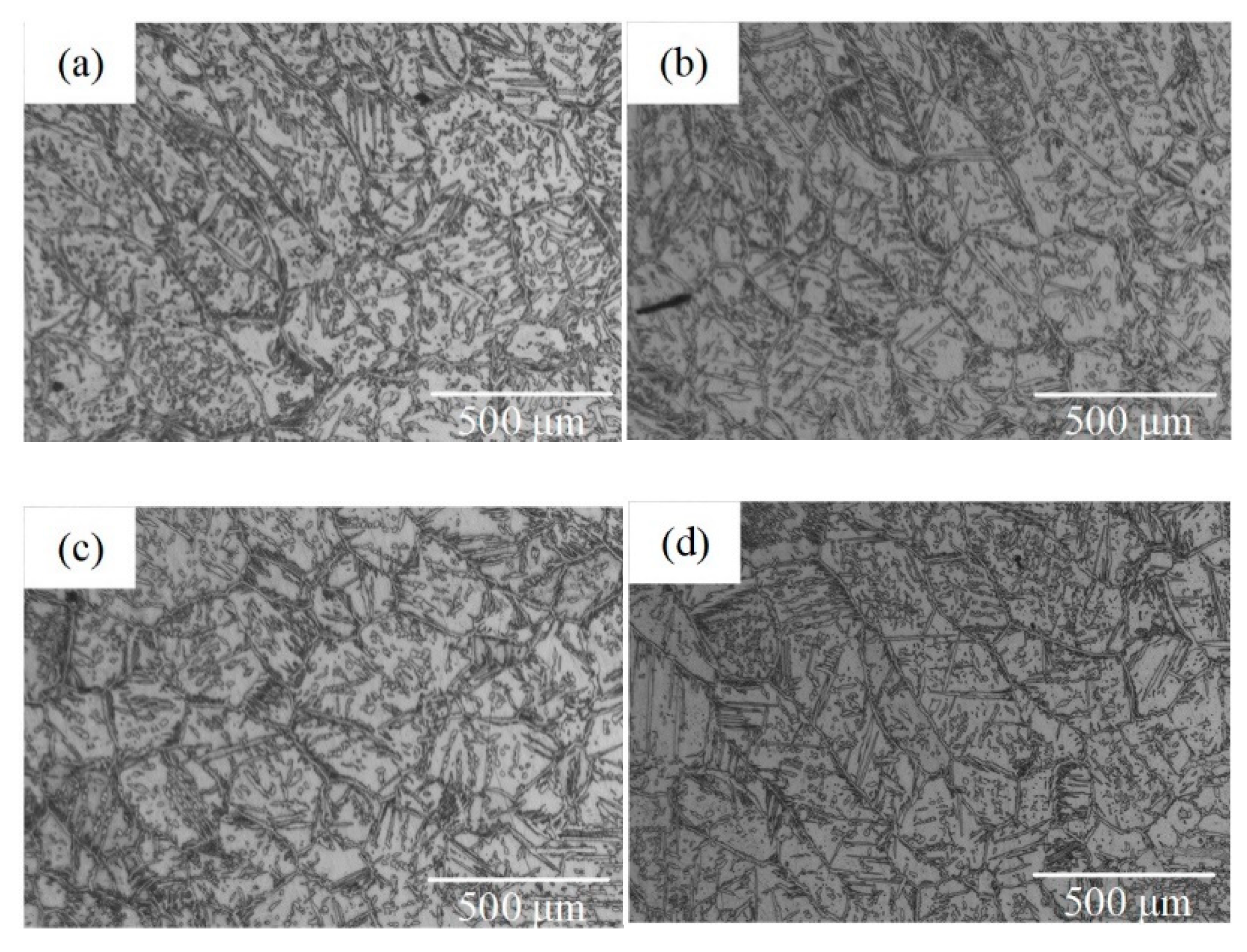
The microstructure of the WMZ obtained at different welding speeds were composed of ferrite and austenite, as shown in the Figure 10. Figure 11 shows the Euler diagram of WMZ under different welding speeds. It can be seen from Figure 10 and Figure 11 as the welding speed increased, the grain size of the WMZ also changed. To measure the grain size of the WMZ more accurately, the EBSD test was performed on the WMZ under different welding speeds. Select the middle of the WMZ as the scan area. The grain size of ferrite and austenite in the WMZ were displayed in Table 4. When the welding speeds were 280–340 mm/min, the average value of the ferrite grain sizes in the WMZ were 17.8 μm, 16.8 μm, 16.3 μm and 16.1 μm, respectively. The average value of the austenite grain sizes in the WMZ were 13.2 μm, 13.1 μm, 13.0 μm and 12.7 μm, respectively. Under different welding speed conditions, the average value of austenite and ferrite grain sizes in the WMZ did not change significantly. But they all gradually decreased with the increase of welding speed.
In DSS materials, the cooling rate also affects the two-phase balance [21,22,23]. When the welding speeds were 280–340 mm/min, the austenite content of the WMZ were 44.8%, 42.1%, 37.4% and 32.7%, respectively. The results of austenite content show that as the welding speed increases, the austenite content decreases significantly. This was because the cooling rate at the same point increased as the welding speed increased, and the austenite did not have enough time to precipitated from the ferrite.

5. Conclusions

This paper verified the accuracy and feasibility of K-TIG welding 2205 DDS through finite element simulation and weld microstructure analysis. The influence of welding speed on the morphology and microstructure of welded joints were studied. And draw the following conclusions:
  • A combined heat source model form using the ellipsoid heat source as the upper part and the conical heat source as the lower part is more suitable in numerical simulation of K-TIG welding.
  • When the welding speeds are 280–340 mm/min, the K-TIG welds are bright silver and continuous. The width of the welds is relatively uniform, and there are no welding defects on the surface of the welds.
  • When the welding speeds are 280–340 mm/min, the simulated molten pool morphologies are close to the actual weld morphologies. The cooling rates of other points were lower than point 1. The cooling rate at the same point increases as the welding speed increases.
  • When the welding speed is increased from 280 mm/min to 340 mm/min, the austenite content and the ferrite and austenite grain size decrease.

Author Contributions

Formal analysis, Z.Z.; Methodology, D.P. and Q.Z.; Writing—original draft, S.P.; Writing—review & editing, S.C. All authors have read and agreed to the published version of the manuscript.

Funding

This work was financially supported from the Science and Technology Base and Talent Special Project of Guangxi Province under Grant number AD19245150 and Guangxi University of Science and Technology Doctoral Fund under Grant number 19Z27.

Data Availability Statement

Not applicable.

Conflicts of Interest

The authors declare no conflict of interest.

References

  1. Wierczyńska, A.; Fydrych, D.; Landowski, M.; Rogalski, G.; Łabanowski, J. Hydrogen embrittlement of X2CrNiMoCuN25-6-3 super duplex stainless steel welded joints under cathodic protection. Constr. Build. Mater. 2020, 238, 117697. [Google Scholar] [CrossRef]
  2. Varbai, B.; Pickle, T.; Májlinger, K. Effect of heat input and role of nitrogen on the phase evolution of 2205 duplex stainless steel weldment. Int. J. Press. Vessel. Pip. 2019, 176, 103952. [Google Scholar] [CrossRef]
  3. Cui, S.W.; Shi, Y.H.; Zhang, C.S. Microstructure and mechanical properties of TC4 titanium alloy K-TIG welded joints. Trans. Nonferrous Met. Soc. China 2021, 31, 416–425. [Google Scholar] [CrossRef]
  4. Cui, S.W.; Shi, Y.H.; Sun, K.; Gu, S. Microstructure evolution and mechanical properties of keyhole deep penetration TIG welds of S32101 duplex stainless steel. Mater. Sci. Eng. A 2018, 709, 214–222. [Google Scholar] [CrossRef]
  5. Cui, S.W.; Shi, Y.H.; Zhu, T.; Liu, W. Microstructure, texture, and mechanical properties of Ti-6Al-4V joints by K-TIG welding. J. Manuf. Process. 2019, 37, 418–424. [Google Scholar] [CrossRef]
  6. Feng, Y.Q.; Luo, Z.; Liu, Z.; Li, Y.; Luo, Y.; Huang, Y. Keyhole gas tungsten arc welding of AISI 316L stainless steel. Mater. Des. 2015, 85, 24–31. [Google Scholar] [CrossRef]
  7. Fan, W.F.; Luo, Z.; Feng, Y.Q.; Li, Y.; Ao, S.S. Study on the Deep Penetration TIG Welding of Q345 Steel. J. Shanghai Jiaotong Univ. 2016, 50, 100–105. [Google Scholar]
  8. Cui, S.L.; Liu, Z.M.; Fang, Y.X.; Luo, Z.; Manladan, S.M.; Yi, S. Keyhole process in K-TIG welding on 4mm thick 304 stainless steel. J. Mater. Process. Technol. 2017, 243, 217–228. [Google Scholar] [CrossRef]
  9. Lange, F.; Artinov, A.; Bachmann, M.; Rethmeier, M.; Hilgenberg, K. Numerical simulation of the weld pool dynamics during pulsed laser welding using adapted heat source models. Procedia CIRP 2018, 74, 679–682. [Google Scholar] [CrossRef]
  10. Chen, S.Y.; Liu, Z.M.; Zhao, X.C.; Lv, Z.Y.; Fan, X.G. Cathode-focused high-current arc: Heat source development with stable keyhole in stationary welding. Int. J. Heat Mass Transf. 2019, 143, 118475.1–118475.13. [Google Scholar] [CrossRef]
  11. Han, T.; Gu, S.W.; Xu, L.; Zhang, H.J.; Ou, Y.K. Study on stress and deformation of keyhole gas tungsten arc-welded joints. Trans. China Weld. Inst. 2019, 29, 21–29. [Google Scholar]
  12. Zhang, R.H.; Li, H.X.; Li, M.; Wang, R.; Leng, X.B. Numerical analysis on keyhole gas tungsten arc welding. Electr. Weld. Machine 2012, 42, 7–11. [Google Scholar]
  13. ASTM International. Designation: E1245-03 (2016) Standard Practice for Determining the Inclusion or Second-Phase Constituent Content of Metals by Automatic Image Analysis; ASTM International: West Conshohocken, PA, USA, 2016. [Google Scholar]
  14. Kik, T.; Moravec, J.; Novakova, I. New method of processing heat treatment experiments with numerical simulation support. IOP Conf. Ser. Mater. Sci. Eng. 2017, 227, 12069. [Google Scholar] [CrossRef] [Green Version]
  15. Devaux, J.; Leblond, J.B.; Bergheau, J.M. Numerical Study of the Plastic Behaviour of a Low Alloy Steel during Phase Transformation. J. Shanghai Jiaotong Univ. 2000, 5, 206–212. [Google Scholar]
  16. Casalino, G.; Mortello, M. A FEM model to study the fiber laser welding of Ti6Al4V thin sheets. Int. J. Adv. Manuf. Technol. 2016, 86, 5–8. [Google Scholar] [CrossRef]
  17. Nadh, H.; Edison, G.; Akella, S.; Buddu, R.K. Simulation of hybrid laser-tig welding process using fea. J. Eng. Sci. Technol. 2018, 13, 1782–1792. [Google Scholar]
  18. Musa, I.U.; Afolayan, M.O.; Dagwa, I.M. Finite element model for predicting residual stresses in shielded manual metal arc welding of mild steel plates. Niger. J. Technol. 2015, 35, 85–90. [Google Scholar] [CrossRef] [Green Version]
  19. Casalino, G.; Michele, D.; Perulli, P. FEM model for TIG hybrid laser butt welding of 6 mm thick austenitic to martensitic stainless steels. Procedia CIRP 2020, 88, 116–121. [Google Scholar] [CrossRef]
  20. Kik, T. Computational Techniques in Numerical Simulations of Arc and Laser Welding Processes. Materials 2020, 13, 608–625. [Google Scholar] [CrossRef] [Green Version]
  21. Cui, S.W.; Shi, Y.H.; Cui, Y.X.; Zhu, T. The influence of microstructure and chromium nitride precipitations on the mechanical and intergranular corrosion properties of K-TIG weld metals. Constr. Build. Mater. 2019, 210, 71–77. [Google Scholar] [CrossRef]
  22. Cui, S.W.; Shi, Y.H.; Cui, Y.X.; Zhu, T. The impact toughness of novel keyhole TIG welded duplex stainless steel joints. Eng. Fail. Anal. 2018, 94, 226–231. [Google Scholar] [CrossRef]
  23. Zhang, Z.Q.; Jing, H.Y.; Xu, L.Y.; Han, Y.; Zhao, L.; Lv, X.; Zhang, J. The impact of annealing temperature on improving microstructure and toughness of electron beam welded duplex stainless steel. J. Manuf. Process. 2018, 31, 568–582. [Google Scholar] [CrossRef]
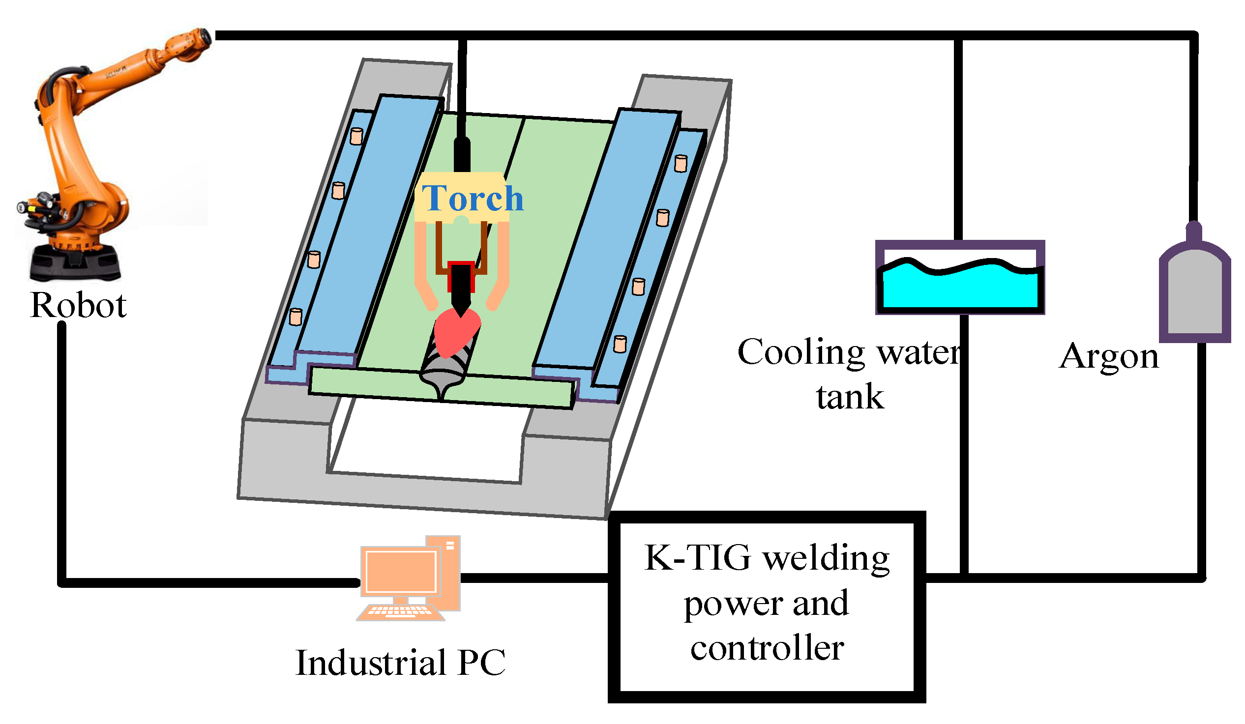
Figure 1. The diagram of k-TIG welding.
Metals 11 01323 g001
Figure 2. Density, specific heat capacity and thermal conductivity of 2205 DSS.
Metals 11 01323 g002
Figure 3. The diagram of combined heat source models. (a) The ellipsoid + the cylindrical, (b) The ellipsoid + the conical, (c) The ellipsoid + the columnar peak increasing.
Metals 11 01323 g003
Figure 4. Shape of Goldak’s double ellipsoid.
Metals 11 01323 g004
Figure 5. Shape of cone heat source model.
Metals 11 01323 g005
Figure 6. The upper and lower surfaces of the K-TIG weld morphologies at different welding speeds: (a) 280 mm/min, (b) 300 mm/min, (c) 320 mm/min, (d) 340 mm/min, (e) 360 mm/min.
Metals 11 01323 g006
Figure 7. The diagram of simulated results and experimental results: (a) The ellipsoid + the cylindrical, (b) The ellipsoid + the conical, (c) The ellipsoid + the columnar peak increasing.
Metals 11 01323 g007
Figure 8. The cross-section of the actual welded joint and the simulated weld pool at different welding speeds: (a) 280 mm/min, (b) 300 mm/min, (c) 320 mm/min, (d) 340 mm/min, (e) 360 mm/min.
Metals 11 01323 g008
Figure 9. Thermal cycle curve of each point under different welding speeds: (a) 280 mm/min, (b) 300 mm/min, (c) 320 mm/min, (d) 340 mm/min.
Metals 11 01323 g009
Figure 10. Metallographic diagram of WMZ under different welding speeds: (a) 280 mm/min, (b) 300 mm/min, (c) 320 mm/min, (d) 340 mm/min.
Metals 11 01323 g010
Figure 11. Euler diagram of WMZ under different welding speeds: (a) 280 mm/min, (b) 300 mm/min, (c) 320 mm/min, (d) 340 mm/min.
Metals 11 01323 g011
Table 1. Welding parameters.
TestArc Voltage (V)Welding Current (A)Welding EfficiencyWelding Speed (mm/min)
117.54800.9280
217.54800.9300
317.54800.9320
417.54800.9340
517.54800.9360
Table 2. The chemical composition of 2205 DSS (wt. %).
ElementCSiMnPSCrNiMoNFe
Wt. %0.01920.5691.4280.0210.000522.465.73.020.156Bal.
Table 3. The parameters of different heat source models.
ParameterThe Double EllipsoidThe CylindricalThe Gaussian Cone Heat SourceThe Columnar Peak Increasing
af/mm4––––––
ar/mm6––––––
b/mm17––––––
c/mm4––––––
m––––––1
H/mm––444
R/mm––3––3.5
re/mm––––3.5––
ri/mm––––1.5––
Table 4. Grain size and austenite content of WMZ.
Welding Speed
(mm/min)
Grain Size (μm)Austenite Content
(%)
FerriteAustenite
28017.813.244.8
30016.813.142.1
32016.313.037.4
34016.112.732.7
Publisher’s Note: MDPI stays neutral with regard to jurisdictional claims in published maps and institutional affiliations.