Article

Interfacial Microstructure and Formation of Direct Laser Welded CFRP/Ti-6Al-4V Joint

1
School of Mechanical and Electrical Engineering, Nanchang University, Nanchang 330031, China
2
Science and Technology College, Nanchang Hangkong University, Jiujiang 332020, China
3
School of Aeronautical Manufacturing Engineering, Nanchang Hangkong University, Nanchang 330031, China
*
Author to whom correspondence should be addressed.
Metals 2021, 11(9), 1398; https://doi.org/10.3390/met11091398
Submission received: 8 August 2021 / Revised: 29 August 2021 / Accepted: 30 August 2021 / Published: 3 September 2021
(This article belongs to the Special Issue Laser Welding Technology)

Abstract

:
Joining fiber reinforced polyether ether ketone resin matrix composite (PEEK-CFRP) with Ti-6Al-4V titanium alloy to form a composite structure is a promising manufacturing process. Huge difference of material properties is the biggies challenge to join them. Continuous laser welding process is conducted in this experiment to join the two materials. In this study, joints under different welding speeds were obtained. Mechanical properties and microstructures were observed, and the interfacial structures were tested. The results showed that fixed joint could be obtained. As the welding speed decreased, the tensile shear first increased and then decreased. The shear force reached a maximum value of 36.8 N/mm at the speed of 10 mm/s. The quality of joint could be observably affected by welding speed. The formation of bubbles, cracks, and anchor effect at the interface were the main factors affecting the mechanical property of joint. Thus, adhesion failure was the main failure form for CFRP fracture. Ti, Al and some other elements had been diffused across the interface, resulting in the formation of intermediate transition layer. The result of EDS, X-ray and XPS test indicated that CTi0.42V1.58 phase could be formed, and Ti at the interface could react with the oxygen and carbon of CFRP to form TiO2, TiO and TiC, forming a stable joint structure.

1. Introduction

With the increasing awareness of environmental protection in the industrial manufacturing industry, manufacturing standard is moving towards the direction of lightweight to reduce carbon emissions and save energy [1,2,3]. Resin based carbon fiber reinforced thermal-plastics (CFRP) is considered as a new type of high-performance composite materials, which obtains the advantages of small density, excellent corrosion resistance and high specific strength [4,5,6]. Therefore, it can be used even as the bearing material applying in the preparation of the aerospace field and crucial parts and components in automobile industry [6,7,8]. However, as the impact toughness and the wear resistance of CFRP is relatively poor, its application are strictly limited in industry [9]. Therefore, a new kind of complex structure combing other materials needs to be prepared in order to give full play to its property. Titanium alloys with superb mechanical properties and corrosion resistance are widely used in the aviation field. In particular, the composite structure formed with CFRP material will not produce interface corrosion [5,10,11]. Therefore, the composite structure formed by CFRP/Titanium alloy has a broad application prospect [12,13].
Since the material properties of CFRP and titanium alloy are quite different, it is difficult to form a firm joint. Therefore, the bonding process between CFRP and titanium alloy is an urgent problem to be solved. Methods like adhesive bonding, bolting, riveting, self-piercing riveting(SPR) and even stir friction weld have already been applied in connecting the two material and obtained a well effect [14,15,16,17]. Laser welding technology, because of its small heat input, moderate thermal deformation and flexible processing, can strictly control the melting area and produce a small heat affected zone [18,19,20]. Therefore, laser welding is a promising hot process that can be applied in connecting CFRP and Titanium [21].
To date, the research focuses of CFRP/titanium alloy structure lays on the formation and annihilation of pores in CFRP material, the interface bonding mechanism and the regulation of joint properties. Tan et al. and Su et al. [22,23] studied the influence of scanning speed and defocus amount on the joint properties of CFRP/titanium alloy laser lap. It was found that the laser process parameters had a direct influence on the mechanical properties of the joint, and by observing the microstructure of the interface joint, a large number of bubbles were produced on the side of the CFRP. Bubble is one of the main factors affecting the quality of welded joint [24,25]. Tan et al. [26] investigated the laser lap welding between the steel and PA6-CFRP and observed that there were two types of bubble near the interface at the side of CFRP. When the heat input was insufficient, a few small and irregular size bubbles would be generated, which were marked as bubble Ⅱ. This kind of bubble were formed due to the fast flowing and solidification of resin. However, when the laser heat input surmounted specific value, beside bubble Ⅱ, a new type of bubble was generated, which was big and smooth, marked as bubble Ⅰ. The bubble Ⅰ was formed when the resin was decomposed during the high temperature recycle. The bonding between CFRP and metal mainly depends on mechanical interlocking and chemical bonding. Zhang et al. [27] studied the laser welding joint between aluminum alloy and PA6-CFRP after anodic oxidation, and found that the melted resin entered into the porous structure of oxidated aluminum alloy during the welding process to form a mechanical interlocking structure. Meanwhile, when observed the microstructure of the interface, the Al-O-C covalent bond was analyzed at the interface, which confirmed that CFRP and metal could form a chemical bond during the laser processing. In order to reveal the bonding mechanism. Su et al. [28] used laser to clad a layer of Ti-6Al-4V on PEEK-CFRP, and then analyze the interface composition to release the bonding mechanism during the hot process. It was found that TiC and TiS compounds were formed at the interface, and the reaction sequence was related to the heat input, which proved that CFRP and titanium alloy could form compounds to improve the joint performance. Presently, there are few studies on the laser welding between CFRP materials and titanium alloy, and the forming mechanism of the joint in the welding process is still unclear.
In this paper, a proper laser lap welding process was carried out to connect the PEEK-CFRP material and Ti-6Al-4V dual-phase titanium alloy and the optimal process parameters were obtained. Combing the mechanical property, the microstructure of joint and the fracture surface were investigated. Finally, interfacial microstructure was tested, which revealed the formation of interface during the welding process and might provide an evidence for the bonding mechanism.

2. Methods

2.1. Materials

In the experiment, carbon fiber reinforced polyethylene ether ketone resin matrix composites (PEEK-CFRP, 30% short carbon fiber + graphite +PTFE) were used, with the processing dimensions 50 mm × 25 mm × 3 mm. The CFRP’s melting point were 343 °C and thermal decomposition temperature were 465 °C. The Ti-6Al-4V dual-phase titanium alloy was chosen because of excellent mechanical property, with processing dimension of 50 mm × 30 mm × 1 mm and the composite of the alloy were shown in Table 1.

2.2. Laser Welding Process

CFRP plates were Rinsed and dried with distilled water before welding and the Ti-6Al-4V titanium alloy was cleaned with 5% NaOH alcohol solution, then cleaned by mixed solution (5%HF + 30%HNO3 + 65%H2O), finally washed, and dried with distilled water. In the welding process, 99.9% pure argon gas was used for side blowing protection, and the flow rate was 25 L·min−1. Generally, the clamping tool and the welding process diagram was shown in Figure 1a. In the experiment, the titanium alloy was placed on the CFRP with a lap length of 20 mm and the clamps and blocks were used to fix the materials. Laser was vertically applied on the surface of titanium alloy and the collimator was installed on the side of laser head to ensure the welding angel. The laser used in the experiment was YLS-2000TR continuous laser generator system produced by IPG Photonics company (Oxford, MA, USA). The emission wavelength is 1069 nm and the beam quality (BPP) is not less than 2 mm-mrad. Then, the focal length is 47 mm and the spot diameter in the focusing state is 0.3 mm. To ensure the welding accuracy, the laser welding system was installed on KUKA’s KR-16 robot, and the parameters could be recorded by computer system.
Laser process parameters are shown in Table 2. In this work, to control the heat input and study the effect of welding speed on the weld, the original laser power was 550 W, the defocus distance was chosen as +6 mm, and the welding speeds ranged from 6 mm/s to 16 mm/s.

2.3. Mechanical Test and Microstructure Analysis

WDW-100 electronic universal tensile machine (Star, Jinan, China)was used to implement tensile test with the tensile rate was 0.5 mm /min. Samples were made as presented in Figure 1b and gaskets were pasted on the samples by epoxy glue to avoid bending effect. Five samples for each parameter were tested to avoid errors. After welding, the macroscopic morphology was recorded, and the cross-section of metallographic sample was well prepared and etched by mixed solution (HF:HNO3:H2O = 1:1.5:2.5) for observation. Optical microscope (OM) (Vihent, Shanghai, China) and field emission scanning electron microscope (FESEM), combing Energy Disperse Spectroscopy (EDS) (Phenom, Eindhoven, The Netherlands) were used to observe the microstructure and the element distribution. To analyze the phase change in the interface, the X-ray diffractometer were applied on the side of Ti-6Al-4V surface to obtain the phase organization.
To collect more information about the interface of the joint, this work used X-ray photoelectron spectroscopy (XPS) to analyze the chemical bonding at the interface. A 4 mm × 4 mm × 4 mm joint sample was prepared and the CFRP was rubbed out by sandpaper so as to reveal the interface of the joint, and then the sample was etched with Ar+ for 30 s. Finally, data were collected on the surface of titanium alloy to analyze the chemical bond formation at the interface, which would be helpful for the bonding mechanism of laser joint.

3. Results and Discussion

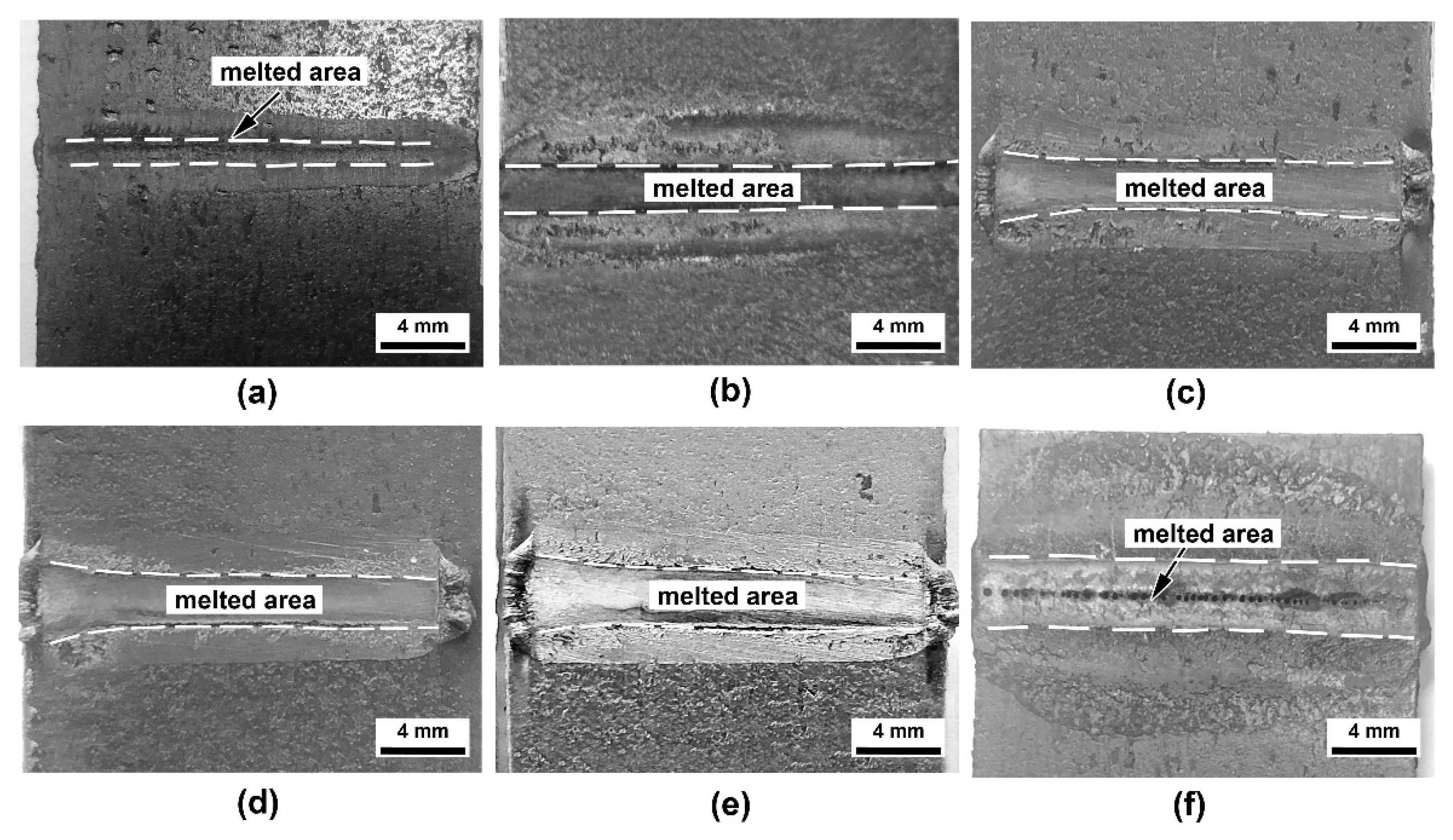
3.1. Joint Appearance

Figure 2 showed the weld morphology of titanium alloy at different welding speeds. Additionally, the average width of welds had been measured and the results were presented in Figure 3. When the welding speed was 16 mm/s and 14 mm/s, the width of the weld was about 1.28 mm and 1.43 mm respectively. The weld displayed metallic luster. As the welding speed decreased, the heat input increased, and the welding seam gradually widened. When the welding speed decreased to 10 mm/s, the width of the welding seam reached 1.78 mm and remained a silver metallic luster. In addition, the accumulation of molten resin appeared on both sides of CFRP. When the welding speed was reduced to 8 mm/s, although the width of the welding seam reached the maximum of 1.98 mm. However, the welding seam was appeared to be gray and seriously oxidized, and many defects such as pores appeared on the surface. As the welding speed reduced to 6 mm/s, the titanium alloy weld had been seriously burned and the weld appearance was poor. Moreover, the joint at the speed of 6 mm/s was weak and were easily broken after welding. In all, the weld quality was appropriate with few defects at the welding speed of 10 mm/s.

3.2. Microstructure of Joint

To study the microstructure of the interface at the power of 550 W and welding speed of 8 mm/s, 10 mm/s and 12 mm/s, 14 mm and 16 mm/s, metallographic observation was made on the weld interfacial area and Figure 4 showed the microstructure of joints. It had been seen from Figure 4a–e that the upper side of the interface was identified as titanium alloy and the other side was CFRP material, and the two materials were closely connected. On the titanium alloy side, the weld area expanded as the welding speed decreased and the weld, while on the side of CFRP material, the weld area was divided into two different zones, namely melted zone and heat affected zone (HAZ). As presented in Figure 3b, when the welding speed decreased, both the width and depth of weld increased. The melted area was closely near the interface and the CFRP in this area had been seriously melted. The HAZ was around the melted zone and numerous bubbles with big size were formed in the heat affect zone. Bubbles can be formed by the decomposition of CFRP and the movement of melted resin during the welding process, as the reference demonstrated before [26]. Details of CFRP had been presented in Figure 4f–j, Few bubbles were formed at the speed of 16 mm/s and 14 mm/s due to the insufficient heat input. As the welding speed down to 12 mm/s, a large number of bubbles were concentrated in the center of weld and cracks were generated at the speed of 8 mm/s. Finally, as presented in Figure 4k–p, small bubbles with the size no more than 40 μm were formed near the interface when speed less than 12 mm/s, which might affect the mechanical property of the joint seriously.
According to the Figure 4k–p, The interface formed at the speed of 16 mm/s,14 mm/s and 12 mm/s were smooth and flat while rough interfaces were formed when welding speed were 10 mm/s and 8 mm/s, respectively. It could be seen that when the welding speed down to the 10 mm/s, the metal and resin penetrated through the interface and mixed with each other, namely, Anchor effect, which was identified as a measure to enhance the mechanical property of the joint.

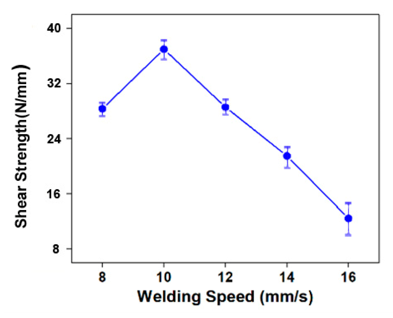
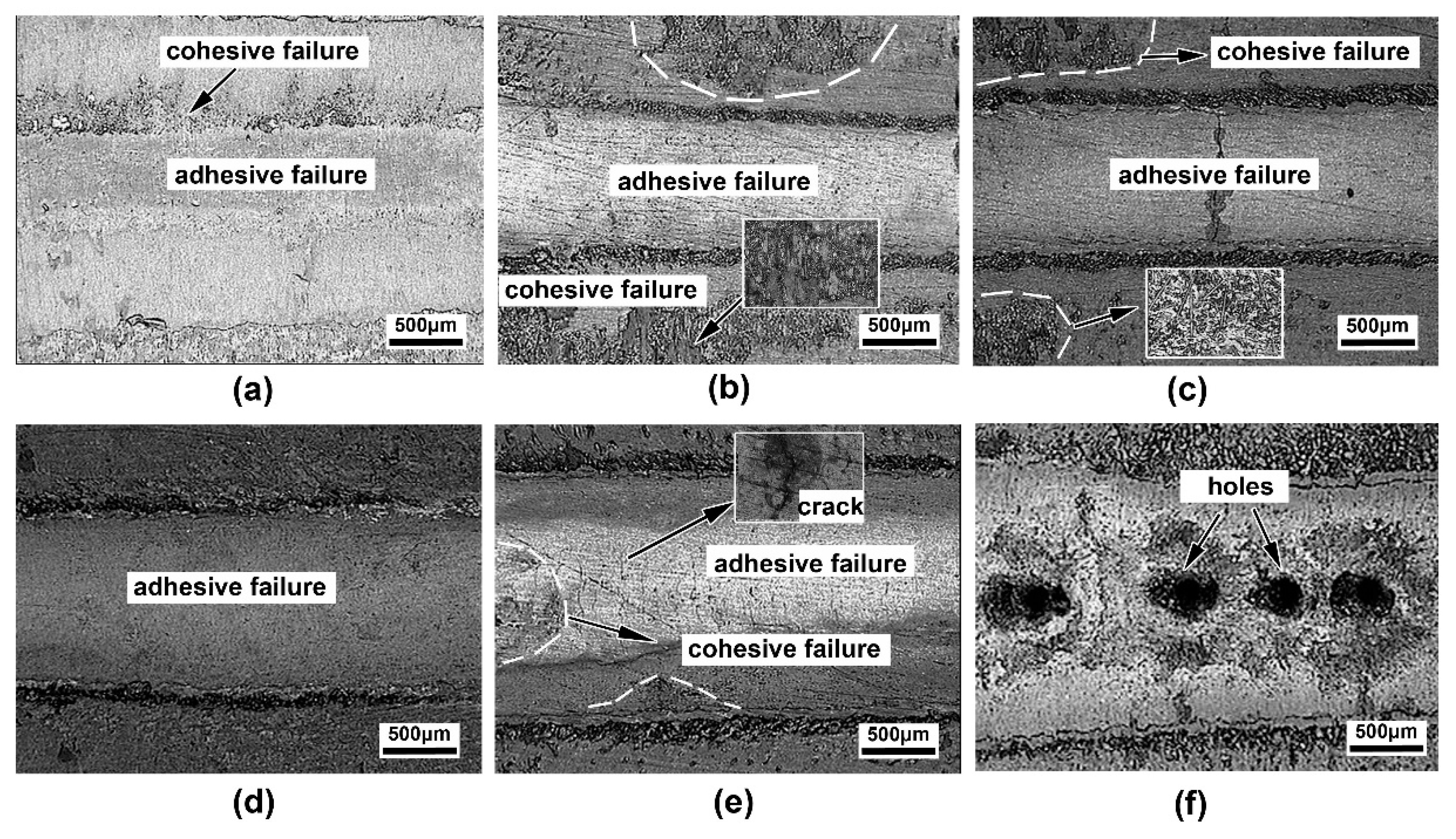
3.3. Mechanical Properties

Figure 5 showed the relationship between the joint strength and the welding speed. It could be obtained from the tensile test results that when the welding speed was 16 mm/s, the tensile shear strength of the joint was 13.1 N/mm as the minimum value. However, as the welding speed gradually decreased, the shear strength of the joint increased gradually. The joint strength reached the maximum value of 36.8 N/mm with the welding speed decreasing to 10 mm/s. Finally, when the welding speed continued to decrease to 8 mm/s, the shear strength decreased to 28.1 N/mm which meant that the welding speed had observably influenced the strength of weld joint.
To further reveal the influence of interface structure and the bubble distribution on mechanical properties, fractures of the CFRP at the welding speed of 16 mm/s, 14 mm/s, 12 mm/s,10 mm/s, 8 mm/s and 6 mm/s were carried out as shown in Figure 6. At the speed of 16 mm/s, the melt area was relatively small and shallow, which might explain the smallest shear strength of joint. When the welding speed decreased, the melted area increased, so as the shear strength of joint. At the speed of 8 mm/s, obvious defects like cracks formed on the surface could reduce the mechanical property of joint, and the fracture had been seriously damaged at the speed of 6 mm/s, as presented in Figure 6e,f respectively. As the reference mentioned before, the failure form can be defined as cohesion failure that occurs inside the materials and adhesion failure that happens in the interface [29,30]. As the CFRP may be melted and degenerated during the welding process, which may weaken the property of CFRP [31]. Therefore, adhesion failure is supposed to be an ideal failure mode in this situation.
Figure 7 showed the details of the fractures. Some rough parts appeared outside the melted area at speed of 16 mm, 14 mm/s and 12 mm/s, which were considered as the cohesive failure that reduce the joint property. In the cohesive failure area, the fracture presented brittle rupture profile and the carbon fibers were exposed as shown in Figure 7b,c respectively. In the melted area, the smooth surface was supposed to be the adhesive fracture that broke in the interface. Figure 7e showed the fracture surface at the speed of 8 mm/s. there were cracks and pores distributed on the surface. The oxides on the surface change the color of the surface and caused residue stress. Therefore, the cracks emerged as the interface underwent heat recycle. Meanwhile, under the overheat in this speed, some parts of the fracture were proved to be cohesion failure as the material had been melted and degenerated in this area. Pores and overheat area were formed at speed of 6 mm/s, seriously damaging the integrity of joint as shown in Figure 7e. By contrast, the fracture surface was relatively smoother, and few defects were formed as the welding speed was 10 mm/s, shown in Figure 7d, which might explain the excellent mechanical property of the joint in this parameter.
Figure 8 showed the SEM of the fracture surface at the welding speed of 10 mm/s. According to the Figure 8b, small bubbles appeared in the center of the weld and a part of carbon fiber are exposed in this area, which proved that the damage area occurred in the interface and the bubbles were one of the main factors affecting the mechanical properties. When approaching the edge of the weld, the surface was rough and had been broken, identified as the transition area. During the welding process, the melted resin on the surface of the CFRP moved to both edges of weld to join the titanium alloy and the heat accumulated at the place would weaken the mechanical of the interface area. Therefore, the transition area showed cohesive fracture. Outside the weld, there were numerous holes in irregular shape distributed in this area and bubble size in this area was larger than that in the weld area. Consequently, it suggested that the bubbles generated both inside or outside the weld could largely affect the joint formation.

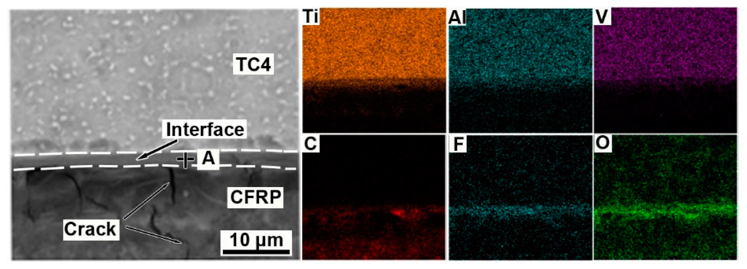
3.4. Analysis of Joint Interfacial Structure

Figure 9 showed the interface and element distribution of the joint at the laser power of 550 W and the welding speed of 10 mm/s. It had been figured out that there were cracks near the interface and a transition layer with thickness of 2 μm was generated between the CFRP and Ti-6Al-4V. The EDS surface scanning analysis of the interface showed that Ti, Al, V, O and F elements were mutually diffused through the interface during the laser scanning process, among which Ti, Al, F and O elements were aggregated on the interface. Combing the result of spot scanning in the interface as shown in Table 3, it could be inferred that Ti, Al, O and F could be precipitated in reaction at the joint interface, and bonds could be formed by chemical reaction. According to the former literatures that the reaction energy of Al and Ti element with C and O was relatively low, and it was promising to form the stable chemical bonds of Ti-O, Ti-C and even Al-O-C in heat processing.
To determine the specific phase structure composition, XRD phase structure analysis was carried out at the side of the titanium alloy fracture section to obtain the diffraction peak diagram as shown in Figure 10. According to PDF card comparison, it could be concluded that there are Ti-O compounds and other phase structure at the interface. According to the literature, titanium could react with oxygen element in CFRP material to form titanium dioxide. Combining the analysis of EDS interface elements and the conclusions in the literature [9], another phase could be inferred as CTi0.42V1.58, which proved that there were compounds generating at the welding interface, thus obtaining a solid welding joint. However, as the phase were obtained from fracture surface, it was difficult to reveal the all the composite that might be generated in the interfacial layer, therefore, more testing method should be introduced to represent the composites with few amounts.

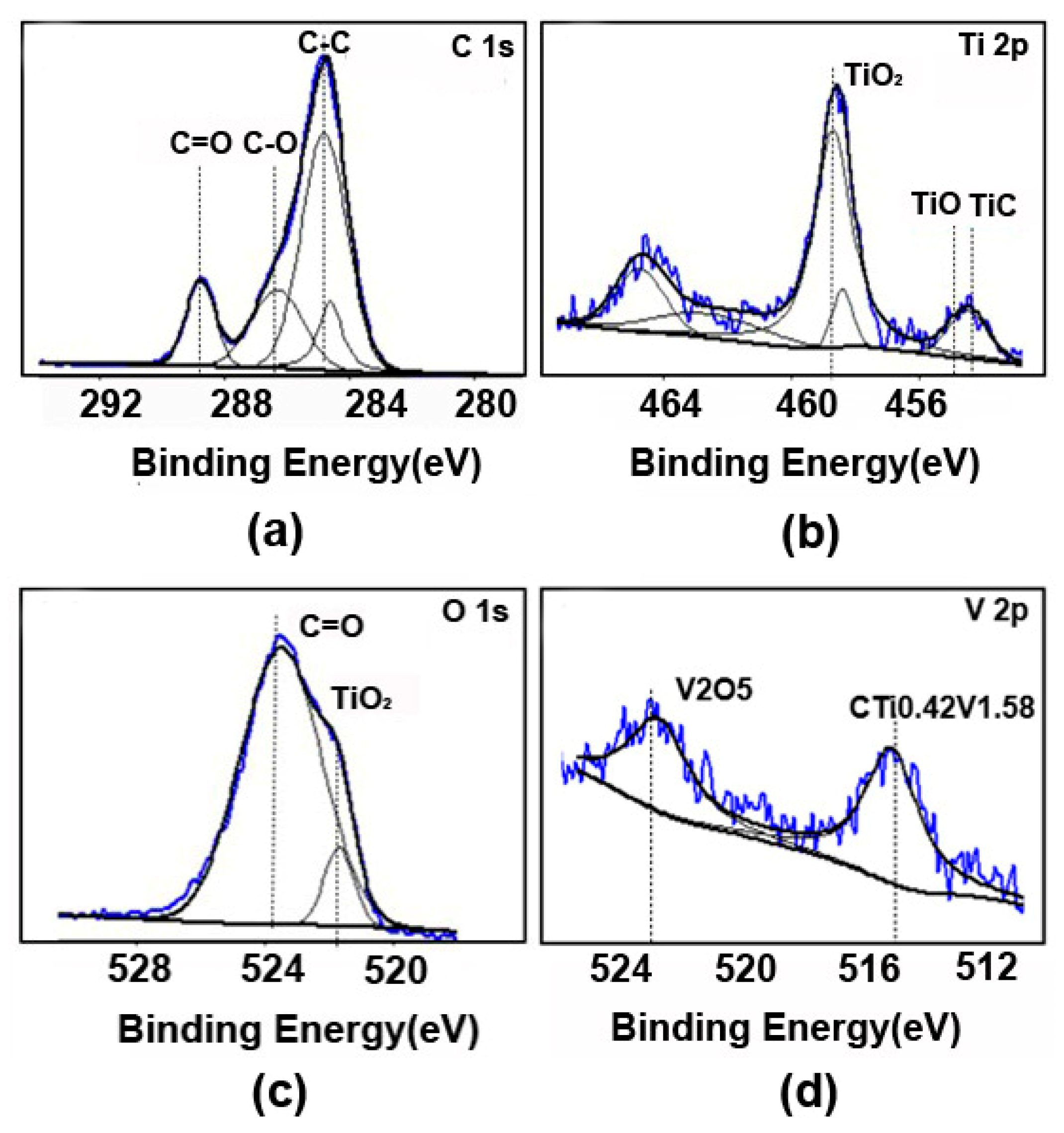
3.5. Analysis of Joint Interface Chemical Bond

To further verify the existence of composites existing at interface precisely. Interfacial chemical bonds should be test by the XPS analysis method. As a result, Ar+ ion etching was carried out on the prepared welded interface for 30 s to dig out more chemical information. Therefore, the spectral peaks of C, O and Ti were obtained, the results of which were shown in Figure 11, and the Peak separation and fitting were manipulated on the spectral peaks. The spectral peaks of C1s element obtained 284.6 eV, 286.4 eV, and 288.5 eV binding energies, which corresponded to the standard C-C bond, the C-H or C-O single bond, and the hydroxyl bond respectively. The C-C bond was the standard carbon peak spectrum, while the C-H or C-O bond might be derived from the -CH- bond or -CO- bond of the CFRP material PEEK. Additionally, the spectral peak corresponding to the 288.5 eV binding energy should be identified as C=O bond, and the source of oxygen element might stem from the TiO2 with strong electronegativity, which forms C=O bond with C in CFRP material. It could be seen from the C spectrum that a relatively weak binding energy of 282.1 eV also appeared in the spectrum. It can be deduced from the reference that TiC might appear at the interface of titanium alloy during the welding process, which was consistent with the results of interface EDS test and insufficient etching time and few amounts might be responsible for the weak spectral peak [32].
Ti 2p orbital spectrum was shown in Figure 11b. According to the 2p1/2 and 2p3/2 orbitals of Ti, there were +2 valence and +4 valence [32,33]. Considering the peak dividing and fitting results of Ti 2p orbit, it could be conformed that the 453 eV bond energy corresponds to Ti in 2p1/2 orbit. Moreover, 454 eV and 455.1 eV binding energy appeared in the spectrum. On the basis of the EDS, XRD and C1S spectra results, they in all possible corresponded to TiC and TiO, respectively, indicating that compounds appear at the reaction interface and metallic bonds appeared in the welding process between titanium alloy and CFRP. Finally, the main peak 458.4 eV binding energy corresponded to TiO2, and the higher peak value Figured out that Ti at the interface was strongly oxidized during the welding process.
Figure 11c showed O1s orbit. It could be known that two peaks were obtained by etching on the surface of titanium alloy, likely the main peak 530.4 eV and 531.9 eV. The binding energy of the main peak 530.4 eV corresponded to the TiO2 valence bond, while 532.1 eV binding energy was defined as C=O bond, probably from PEEK’ functional group. It could be concluded that during the welding process of titanium alloy and CFRP, titanium alloy was oxidized to form TiO2, and TiC were obtained to form a transition layer, which also proved that there was a chemical bond between titanium alloy and CFRP, and it provided a corresponding basis for the bonding mechanism between titanium alloy and CFRP. The 2p orbital spectrum of V were shown in Figure 11d. It could be deduced from the XRD results that the 515 eV bonding energy of V 1/2p were in line with the CTi0.42V1.58 compounds while the 522 eV were likely to represent the V2O5 as the V might react with O in the interface during laser welding process, which was accorded with the results of V element distribution in EDS test. Generally, Combining the EDS, XRD and XPS test, CTi0.42V1.58 phase could be tested at the interface. Moreover, Ti at the interface could react with the oxygen and carbon of CFRP to form TiO2, TiO and TiC.

4. Conclusions

PEEK-CFRP/Ti-6Al-4V titanium alloy were successfully welded to obtain a stable joint by laser process. The weld morphology and fracture interface at different welding speeds were analyzed. In addition, the structure of the joint interface was characterized, and the factors affecting the mechanical properties of the fracture interface were revealed. The microstructure of the joint phase the chemical bonds of the joint interface were analyzed and characterized. Therefore, the following results can be obtained:
1. When the welding speed was 10 mm/s, the welding quality of Ti-6Al-4V side was better with fewer defects. The tensile shear strength of the joint first increase and then decreased as the welding speed decreased, and a fixed join with the maximum value of 36.8 N/mm could be obtained at the speed of 10 mm/s.
2. Welding speed could observably affect the formation of bubbles, cracks, and anchor effect at the interface of CFRP which were the main factors affecting the mechanical property of joint. Bubbles could be formed both near and at the weld area due to the decomposition of CFRP and the movement of melted resin. The anchor effect at the interface and the adhesion failure forms with few cracks might explain the excellent mechanical property of the joint at the speed of 10 mm/s.
3. According to results of EDS, XRD and XPS, CTi0.42V1.58 phase could be tested at the interface. Moreover, Ti at the interface could react with the oxygen and carbon of CFRP to form TiO2, TiO and TiC, thus forming a stable joint structure.

Author Contributions

Conceptualization: P.Z. and H.Z.; Methodology: S.H. and F.Y.; Validation: D.C. and M.L. All authors have read and agreed to the published version of the manuscript.

Funding

This work was supported by the fund of Superior Technology Innovation Team Project (Grant No: 20181BCB24001) and Science and Technology Research Project of Education Department (Grant No: GJJ181568).

Institutional Review Board Statement

Not applicable.

Informed Consent Statement

Not applicable.

Data Availability Statement

This study did not produce any publicly archived data. The data shown in this study are available on request from the corresponding author.

Acknowledgments

This work was supported by the fund of Superior Technology Innovation Team Project and Science and Technology Research Project of Education Department.

Conflicts of Interest

The authors declared no conflict of interest.

References

  1. Chen, Y.; Yue, T.M.; Guo, Z. A new laser joining technology for direct-bonding of metals and plastics. Mater. Des. 2016, 110, 775–781. [Google Scholar] [CrossRef]
  2. Jung, K.-W.; Kawahito, Y.; Takahashi, M.; Katayama, S. Laser direct joining of carbon fiber reinforced plastic to aluminum alloy. J. Laser Appl. 2013, 25, 032003. [Google Scholar] [CrossRef]
  3. Jung, K.; Kawahito, Y.; Takahashi, M.; Katayama, S. Laser direct joining of carbon fiber reinforced plastic to zinc-coated steel. Mater. Des. 2013, 47, 179–188. [Google Scholar] [CrossRef]
  4. Zhang, Z.; Shan, J.; Tan, X. Evaluation of the CFRP grafting and its influence on the laser joining CFRP to aluminum alloy. J. Adhes. Sci. Technol. 2017, 32, 390–406. [Google Scholar] [CrossRef]
  5. Kashaev, N.; Ventzke, V.; Riekehr, S.; Dorn, F.; Horstmann, M. Assessment of alternative joining techniques for Ti–6Al–4V/CFRP hybrid joints regarding tensile and fatigue strength. Mater. Des. 2015, 81, 73–81. [Google Scholar] [CrossRef] [Green Version]
  6. Zuo, Y.; Cao, Z.; Cao, Y.; Zhang, Q.; Wang, W. Dynamic behavior of CFRP/Ti single-lap pinned joints under longitudinal electromagnetic dynamic loading. Compos. Struct. 2018, 184, 362–371. [Google Scholar] [CrossRef]
  7. Sun, G.; Yu, H.; Wang, Z.; Xiao, Z.; Li, Q. Energy absorption mechanics and design optimization of CFRP/aluminium hybrid structures for transverse loading. Int. J. Mech. Sci. 2018, 150, 767–783. [Google Scholar] [CrossRef]
  8. Pramanik, A.; Basak, A.; Dong, Y.; Sarker, P.; Uddin, M.; Littlefair, G.; Dixit, A.R.; Chattopadhyaya, S. Joining of carbon fibre reinforced polymer (CFRP) composites and aluminium alloys—A review. Compos. Part A Appl. Sci. Manuf. 2017, 101, 1–29. [Google Scholar] [CrossRef] [Green Version]
  9. Meredith, J.; Bilson, E.; Powe, R.; Collings, E.; Kirwan, K. A performance versus cost analysis of prepreg carbon fibre epoxy energy absorption structures. Compos. Struct. 2015, 124, 206–213. [Google Scholar] [CrossRef] [Green Version]
  10. Murakami, S.; Ozaki, K.; Ono, K.; Itsumi, Y. Effect of Alloy Elements on Machinability and Hot Workability of A-Fi Titanium Alloy Containing Fe and C; Secretariat & Publicity Dept. Kobe Steel, Ltd.: Kobe, Japan, 2010. [Google Scholar]
  11. Zhang, Z.; Shan, J.; Tan, X.; Zhang, J. Improvement of the laser joining of CFRP and aluminum via laser pre-treatment. Int. J. Adv. Manuf. Technol. 2016, 90, 3465–3472. [Google Scholar] [CrossRef]
  12. Molitor, P.; Barron, V.; Young, T. Surface treatment of titanium for adhesive bonding to polymer composites: A review. Int. J. Adhes. Adhes. 2001, 21, 129–136. [Google Scholar] [CrossRef]
  13. Wang, K.; Shriver, D.; Li, Y.; Banu, M.; Hu, S.; Xiao, G.; Arinez, J.; Fan, H.-T. Characterization of weld attributes in ultrasonic welding of short carbon fiber reinforced thermoplastic composites. J. Manuf. Process. 2017, 29, 124–132. [Google Scholar] [CrossRef]
  14. Joesbury, A.M.; Colegrove, P.; Van Rymenant, P.; Ayre, D.; Ganguly, S.; Williams, S. Weld-bonded stainless steel to carbon fibre-reinforced plastic joints. J. Mater. Process. Technol. 2018, 251, 241–250. [Google Scholar] [CrossRef]
  15. Wu, L.; Xiao, B.; Nagatsuka, K.; Nakata, K.; Ma, Z. Achieving strong friction lap joints of carbon-fiber reinforced plastic and metals by modifying metal surface structure via laser-processing pretreatment. Compos. Struct. 2020, 242, 112167. [Google Scholar] [CrossRef]
  16. He, X. A review of finite element analysis of adhesively bonded joints. Int. J. Adhes. Adhes. 2011, 31, 248–264. [Google Scholar] [CrossRef]
  17. Haque, R. Quality of self-piercing riveting (SPR) joints from cross-sectional perspective: A review. Arch. Civ. Mech. Eng. 2018, 18, 83–93. [Google Scholar] [CrossRef]
  18. Schricker, K.; Stambke, M.; Bergmann, J.P.; Bräutigam, K. Laser-Based Joining of Thermoplastics to Metals: Influence of Varied Ambient Conditions on Joint Performance and Microstructure. Int. J. Polym. Sci. 2016, 2016, 5301081. [Google Scholar] [CrossRef] [Green Version]
  19. Wahba, M.; Kawahito, Y.; Katayama, S. Laser direct joining of AZ91D thixomolded Mg alloy and amorphous polyethylene terephthalate. J. Mater. Process. Technol. 2011, 211, 1166–1174. [Google Scholar] [CrossRef]
  20. Lambiase, F.; Genna, S. Laser-assisted direct joining of AISI304 stainless steel with polycarbonate sheets: Thermal analysis, mechanical characterization, and bonds morphology. Opt. Laser Technol. 2017, 88, 205–214. [Google Scholar] [CrossRef]
  21. Lambiase, F.; Genna, S. Laser assisted joining of AA5053 aluminum alloy with polyvinyl chloride (PVC). Opt. Laser Technol. 2018, 107, 80–88. [Google Scholar] [CrossRef]
  22. Su, J.; Tan, C.; Wu, Z.; Wu, L.; Gong, X.; Chen, B.; Song, X.; Feng, J. Influence of defocus distance on laser joining of CFRP to titanium alloy. Opt. Laser Technol. 2019, 124, 106006. [Google Scholar] [CrossRef]
  23. Tan, C.; Su, J.; Zhu, B.; Li, X.; Wu, L.; Chen, B.; Song, X.; Feng, J. Effect of scanning speed on laser joining of carbon fiber reinforced PEEK to titanium alloy. Opt. Laser Technol. 2020, 129, 106273. [Google Scholar] [CrossRef]
  24. Schricker, K.; Diller, S.; Bergmann, J.P. Bubble formation in thermal joining of plastics with metals. Procedia CIRP 2018, 74, 518–523. [Google Scholar] [CrossRef]
  25. Wang, H.; Chen, Y.; Guo, Z.; Guan, Y. Porosity Elimination in Modified Direct Laser Joining of Ti6Al4V and Thermoplastics Composites. Appl. Sci. 2019, 9, 411. [Google Scholar] [CrossRef] [Green Version]
  26. Tan, X.; Zhang, J.; Shan, J.; Yang, S.; Ren, J. Characteristics and formation mechanism of porosities in CFRP during laser joining of CFRP and steel. Compos. Part B Eng. 2015, 70, 35–43. [Google Scholar] [CrossRef]
  27. Zhang, Z.; Shan, J.-G.; Tan, X.-H.; Zhang, J. Effect of anodizing pretreatment on laser joining CFRP to aluminum alloy A6061. Int. J. Adhes. Adhes. 2016, 70, 142–151. [Google Scholar] [CrossRef]
  28. Su, X.; Tao, W.; Chen, Y.; Chen, X.; Tian, Z. Microstructural characteristics and formation mechanism of laser cladding of titanium alloys on carbon fiber reinforced thermoplastics. Mater. Lett. 2017, 195, 228–231. [Google Scholar] [CrossRef]
  29. Montois, P.; Nassiet, V.; Petit, J.A.; Adrian, D. Viscosity effect on epoxy-diamine/metal interphases—Part II: Mechanical resistance and durability. Int. J. Adhes. Adhes. 2007, 27, 145–155. [Google Scholar] [CrossRef]
  30. Tao, W.; Su, X.; Chen, Y.; Tian, Z. Joint formation and fracture characteristics of laser welded CFRP/TC4 joints. J. Manuf. Process. 2019, 45, 1–8. [Google Scholar] [CrossRef]
  31. Jung, D.-J.; Cheon, H.; Na, S.-J. Effect of surface pre-oxidation on laser assisted joining of acrylonitrile butadiene styrene (ABS) and zinc-coated steel. Mater. Des. 2016, 99, 1–9. [Google Scholar] [CrossRef]
  32. Georgiev, G.L.; Sultana, T.; Baird, R.J.; Auner, G.; Newaz, G.; Patwa, R.; Herfurth, H. XPS study of laser fabricated titanium/KaptonFN interfaces. Appl. Surf. Sci. 2008, 254, 7173–7177. [Google Scholar] [CrossRef]
  33. Sultana, T.; Georgiev, G.L.; Auner, G.; Newaz, G.; Herfurth, H.J.; Patwa, R. XPS analysis of laser transmission micro-joint between poly (vinylidene fluoride) and titanium. Appl. Surf. Sci. 2008, 255, 2569–2573. [Google Scholar] [CrossRef]
Figure 1. (a) Laser lap joining schematic illustration, (b) Illustration for the tensile sample in this study.
Metals 11 01398 g001
Figure 2. Weld morphology of titanium alloy at different welding speeds with welding power of 550 W, (a) 16 mm/s, (b) 14 mm/s, (c) 12 mm/s, (d) 10 mm/s, (e) 8 mm/s and (f) 6 mm.
Metals 11 01398 g002
Figure 3. (a) Relationship between welding speed and the width of weld of Titanium alloy; (b) The effect of welding speed on width and depth of weld of CFRP.
Metals 11 01398 g003
Figure 4. Morphology of joints at speed of (a) 16 mm/s, (b) 14 mm/s, (c) 12 mm/s, (d) 10 mm/s and (e) 8 mm/s; Details of the joints at speed of (f) 16 mm/s, (g) 14 mm/s, (h) 12 mm/s, (i) 10 mm/s and (j) 8 mm/s; Interfacial structure of joints at speed of (k) 16 mm/s, (q) 14 mm/s, (m) 12 mm/s, (n) 10 mm/s and (p) 8 mm/s.
Metals 11 01398 g004
Figure 5. The relationship between the welding speed and Shear strength.
Metals 11 01398 g005
Figure 6. The fracture surface of CFRP at different welding speed: (a) 16 mm/s, (b) 14 mm/s, (c) 12 mm/s, (d) 10 mm/s, (e) 8 mm/s, and (f) 6 mm/s.
Metals 11 01398 g006
Figure 7. Details of fracture surface at different welding speed: (a) 16 mm/s, (b) 14 mm/s, (c) 12 mm/s, (d) 10 mm/s, (e) 8 mm/s, and (f) 6 mm/s.
Metals 11 01398 g007
Figure 8. The microstructure of the joint under the power of 550 W and welding speed of 10 mm/s. (a) the bonding area appearance; (bd) the structures corresponding to the area of B, C, D marked in (a).
Metals 11 01398 g008
Figure 9. The mapping elements scanning results of the interface at speed of 10 mm/s.
Metals 11 01398 g009
Figure 10. The XRD phase analysis of the Ti-6Al-4V bonding surface at speed of 10 mm/s.
Metals 11 01398 g010
Figure 11. The spectrum schematic image of XPS of Ti-6Al-4V (a) the peak of C element, (b) the peak of titanium element, (c) the peak of O element, and (d) the peak of V element.
Metals 11 01398 g011
Table 1. The composition of Ti-6Al-4V.
ElementAlVFeCONTi
content5.5–6.753.5–4.5≤0.5≤0.1≤0.2≤0.05Bal
Table 2. Laser welding process parameters.
Laser ParameterValue
Power550 W
Defocus distance+6
Welding speed16 mm/s, 14 mm/s, 12 mm/s, 10 mm/s, 8 mm/s, 6 mm/s
Table 3. Element content of spot A in Figure 9.
Elementwt%at%
C62.1577.97
O15.6814.77
Al1.150.64
Ti21.026.61
Publisher’s Note: MDPI stays neutral with regard to jurisdictional claims in published maps and institutional affiliations.

