
Microstructure and Mechanical Properties of Spark Plasma Sintered and Severely Deformed AA7075 Alloy

 ,
,  , ,
, ,
Abstract
:1. Introduction
2. Materials and Methods
3. Results
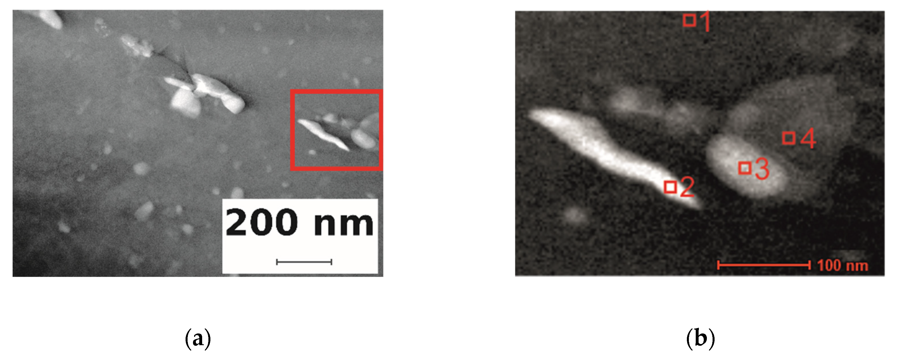
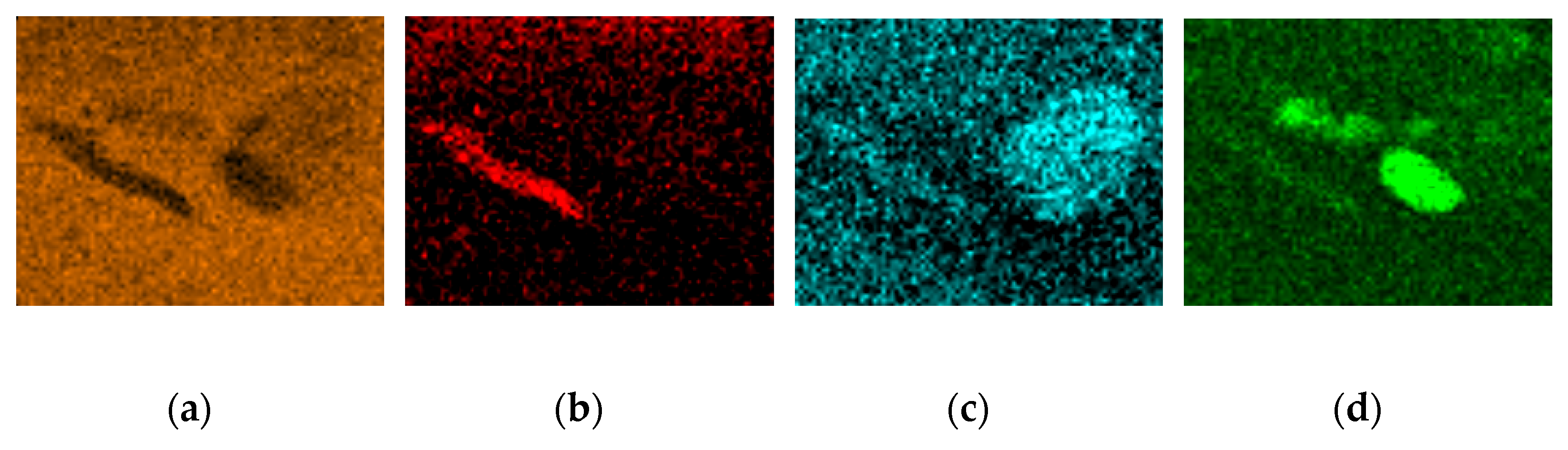
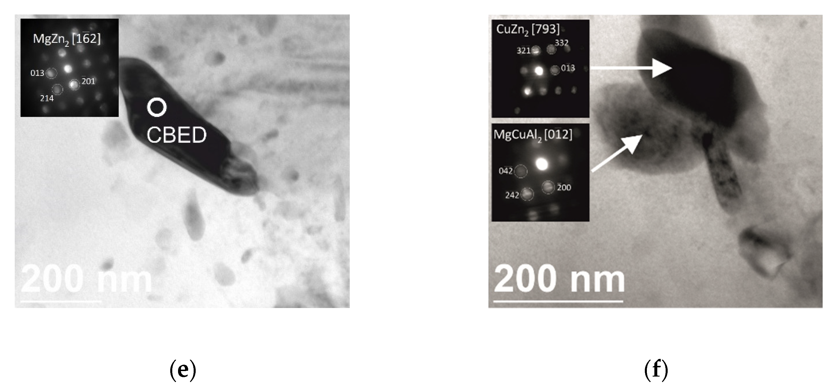
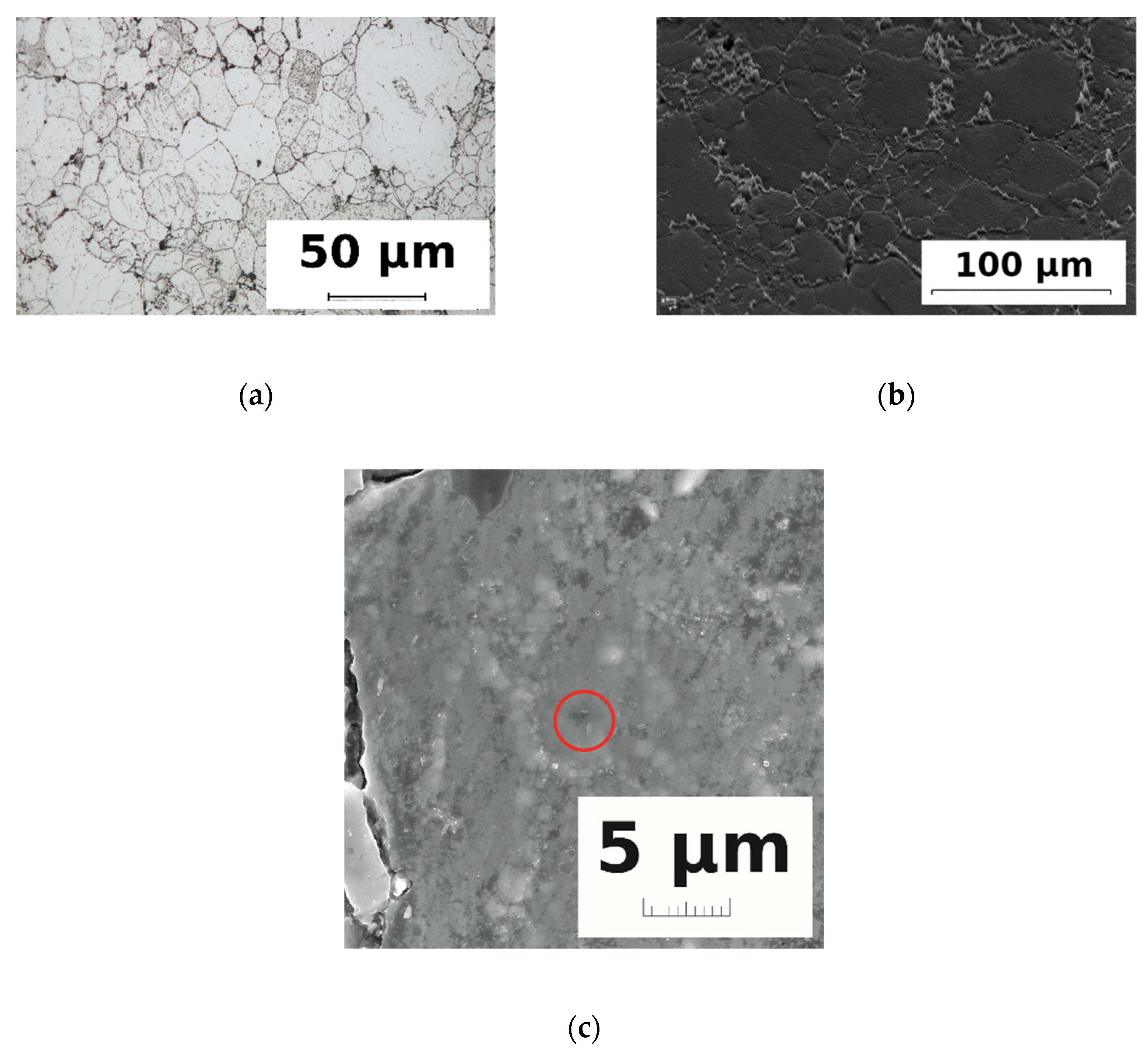
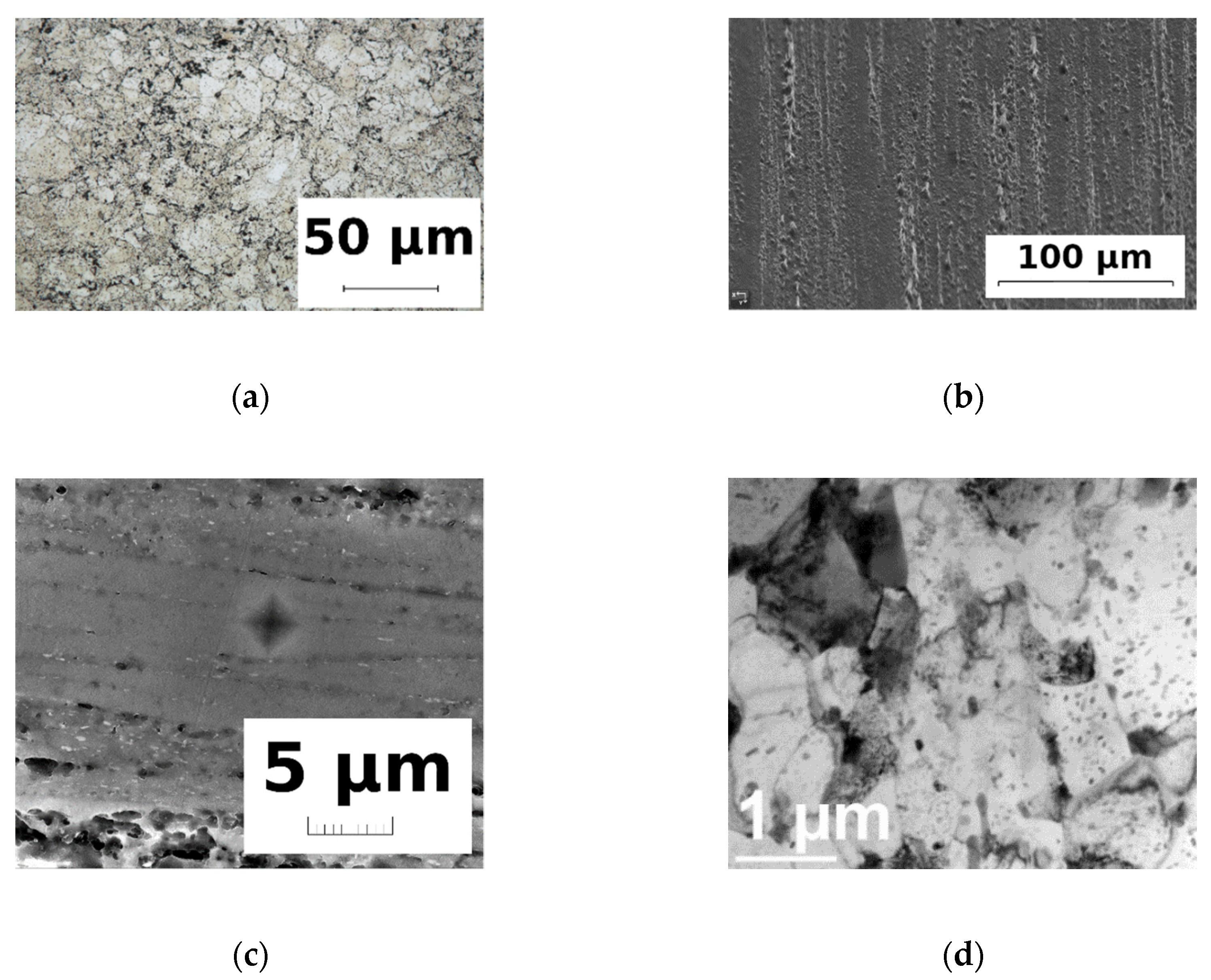
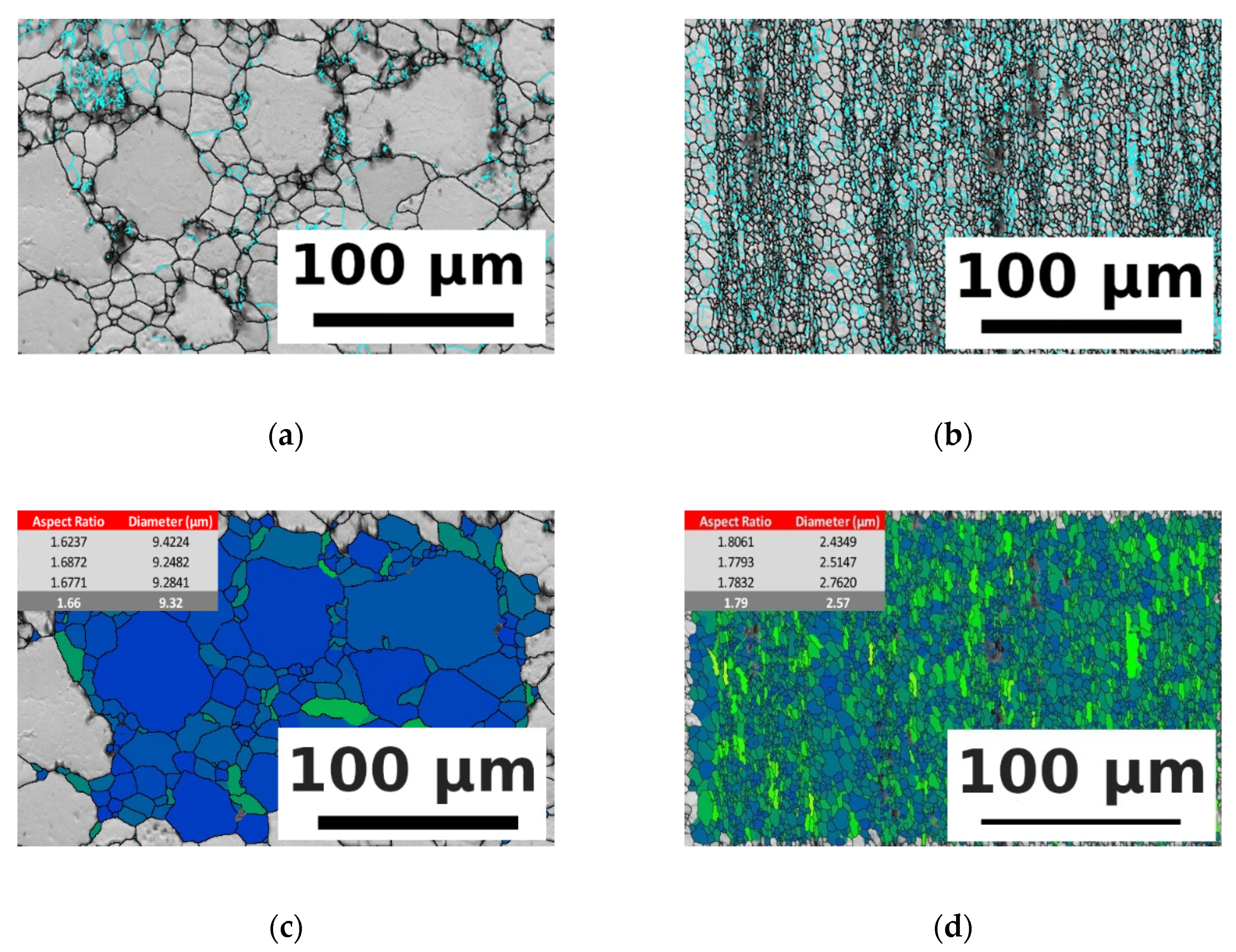
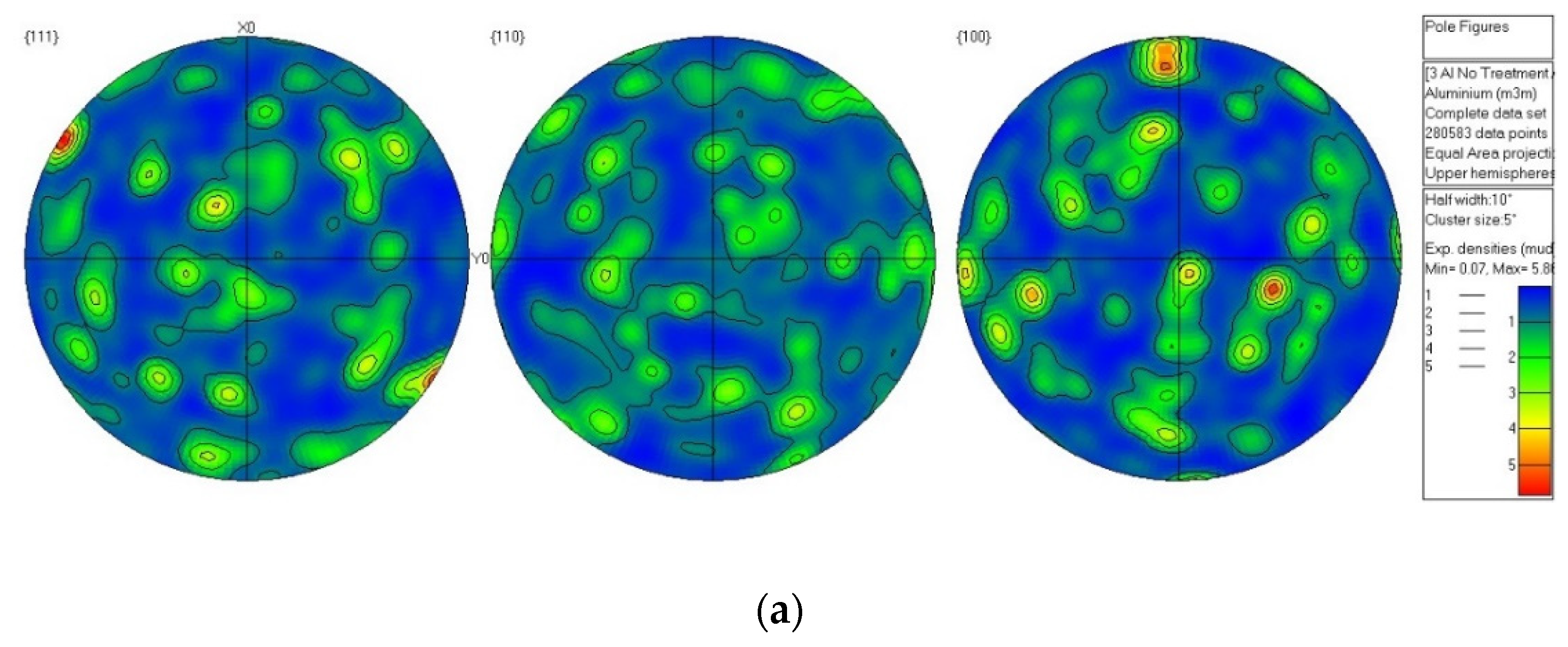
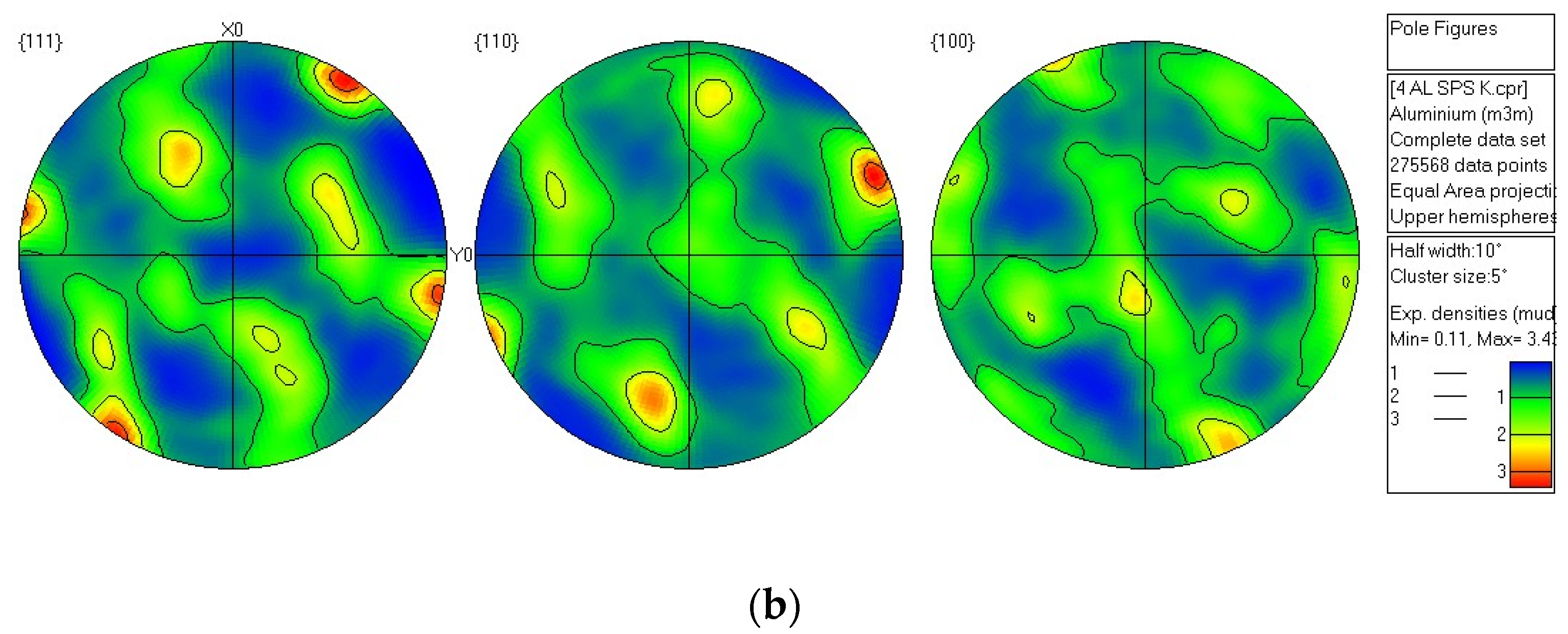
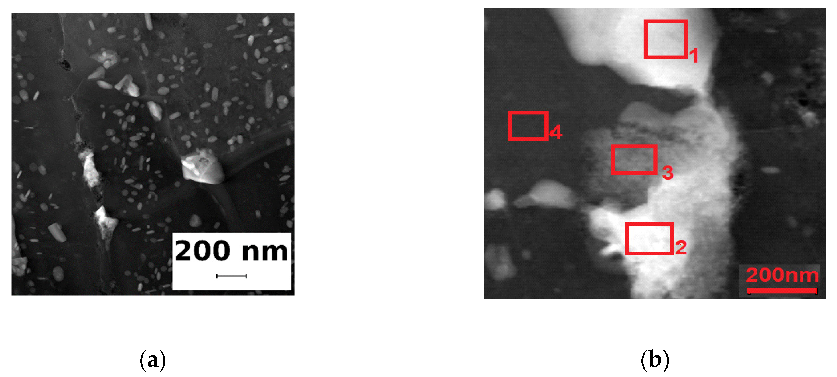
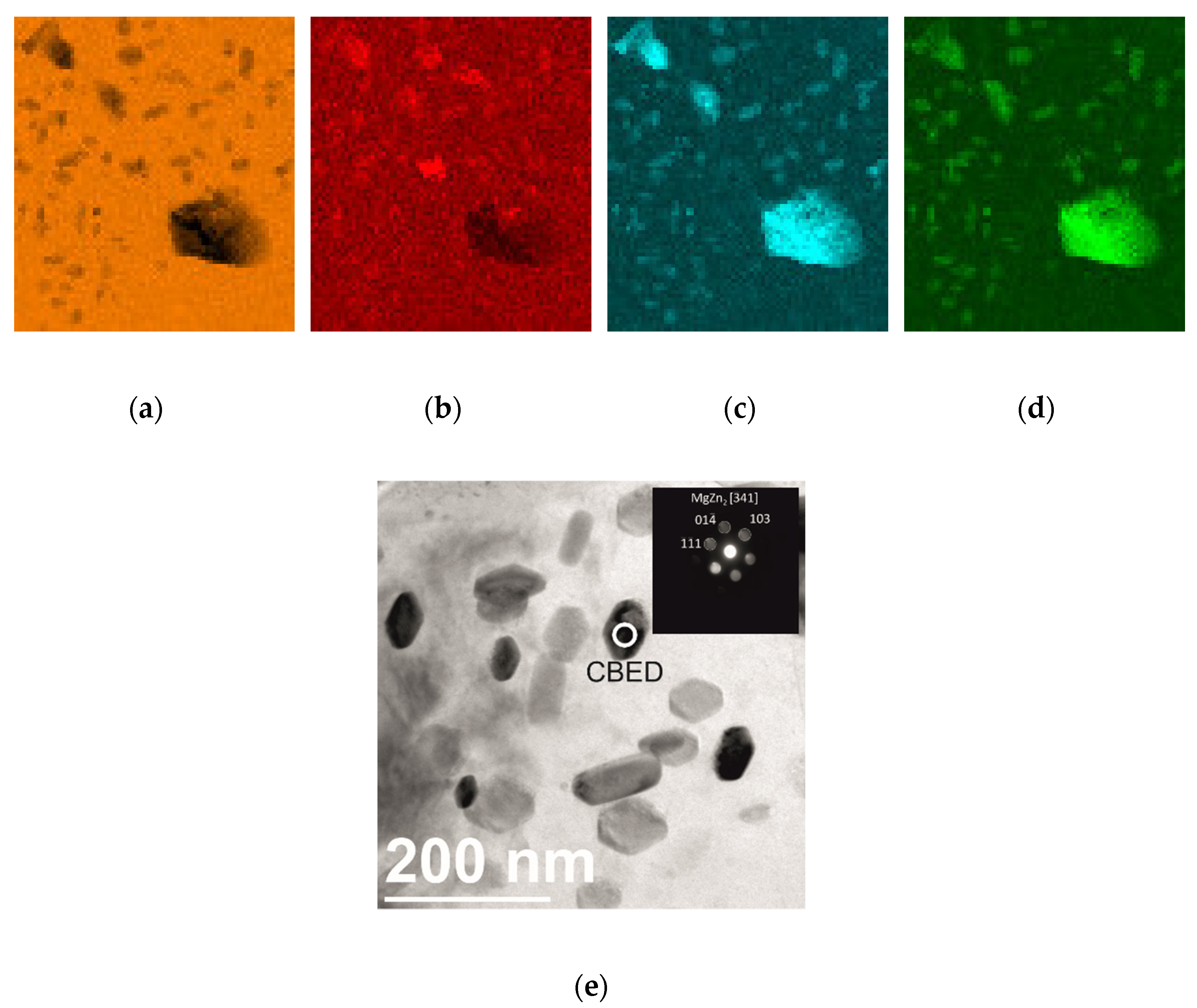
3.1. Microstructure
3.2. Mechanical Properties
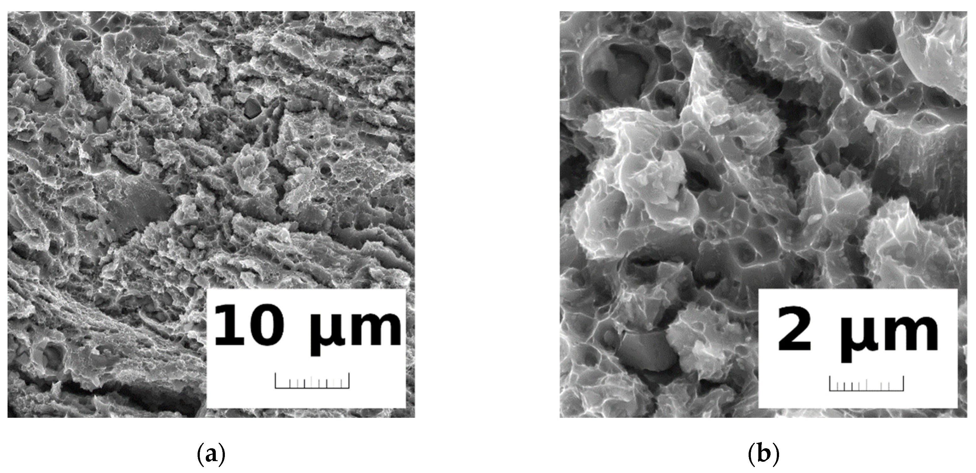
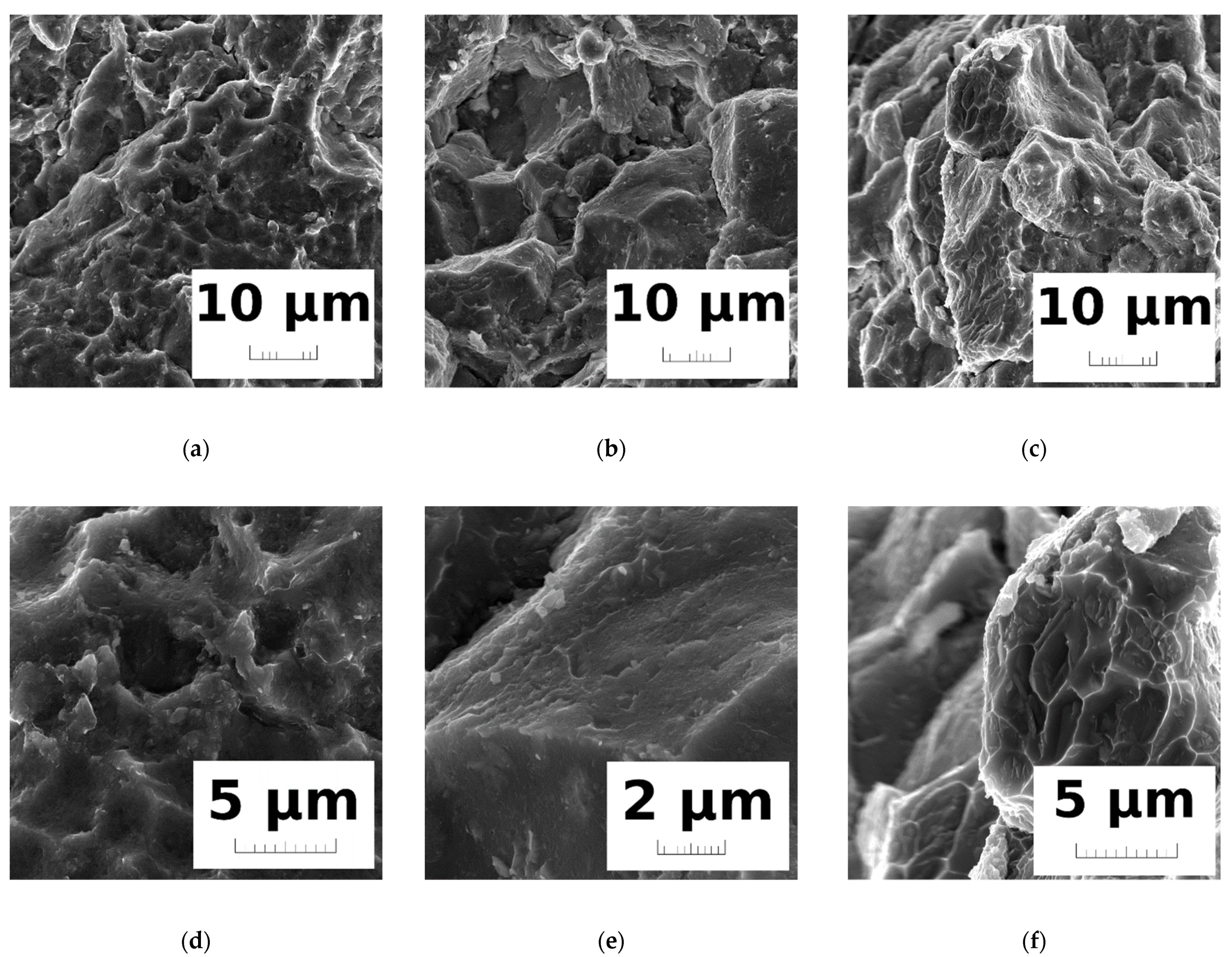
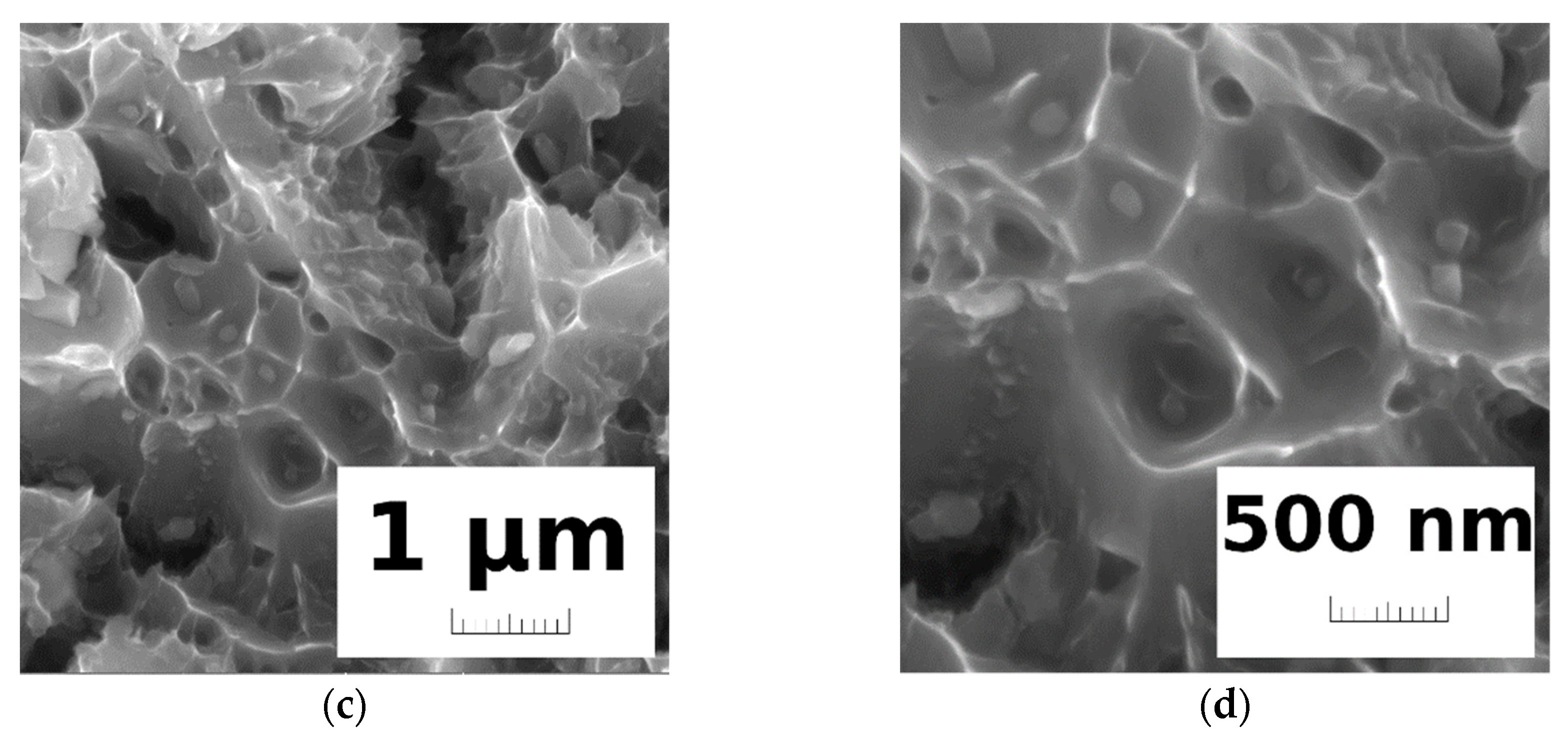
3.3. Fractographic Analysis
- dimples indicating the occurrence of mostly ductile fracture (Figure 11c,f);
- areas of a flat microstructure (cleavage), indicating intergranular fracture (Figure 11b,e);
- dimples indicating plastic deformation in addition to traditional void nucleation and coalescence processes, together with cleavage features corresponding to brittle fracture (Figure 11a,d).
4. Discussion
5. Conclusions
- It was found that the microstructure synthesized by the SPS process was inhomogeneous, formed by coarse and fine grains randomly distributed within the matrix, and developed into a coarse- and fine-grained laminated microstructure by a subsequent KOBO extrusion process at room temperature. The dominant microstructure formation mechanisms were dislocation accumulation and dynamic recrystallization during SPS plus KOBO extrusion severe deformation processes;
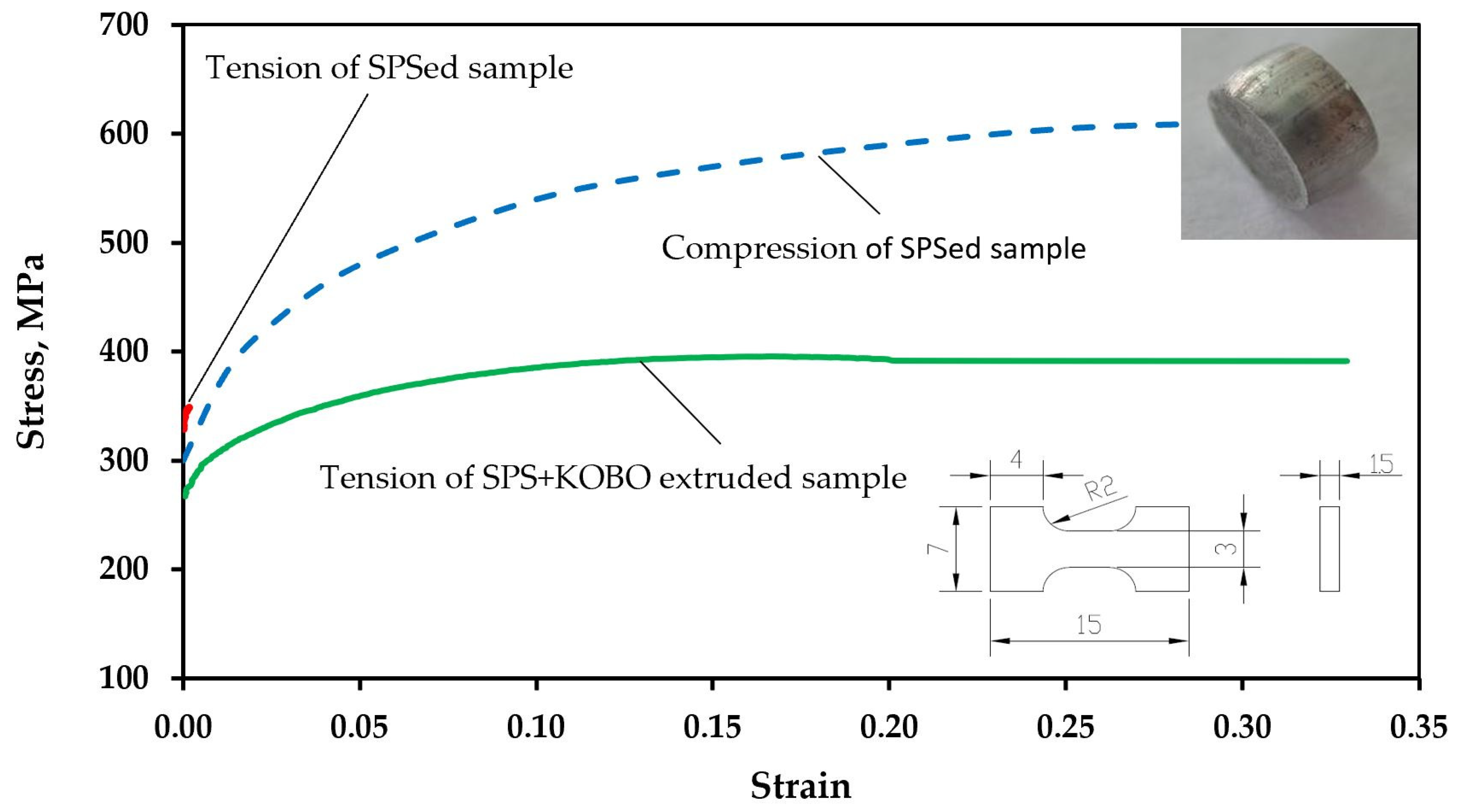
- The ultimate tensile strength (UTS) of the AA7075 rose after the SPS-KOBO severe deformation up to 400 MPa, exhibiting high strain of 33%. This effect was achieved due to the formation of a coarse–fine laminated grained microstructure;
- It was found that the intermetallic precipitates seemed to be preferred sites for the nucleation of voids and cracks due to the high local strains achieved during the tensile tests, and the SPS-KOBO extruded composite micro-mechanical behaviour greatly depended on its dislocation microstructure, precipitates, and grain morphology;
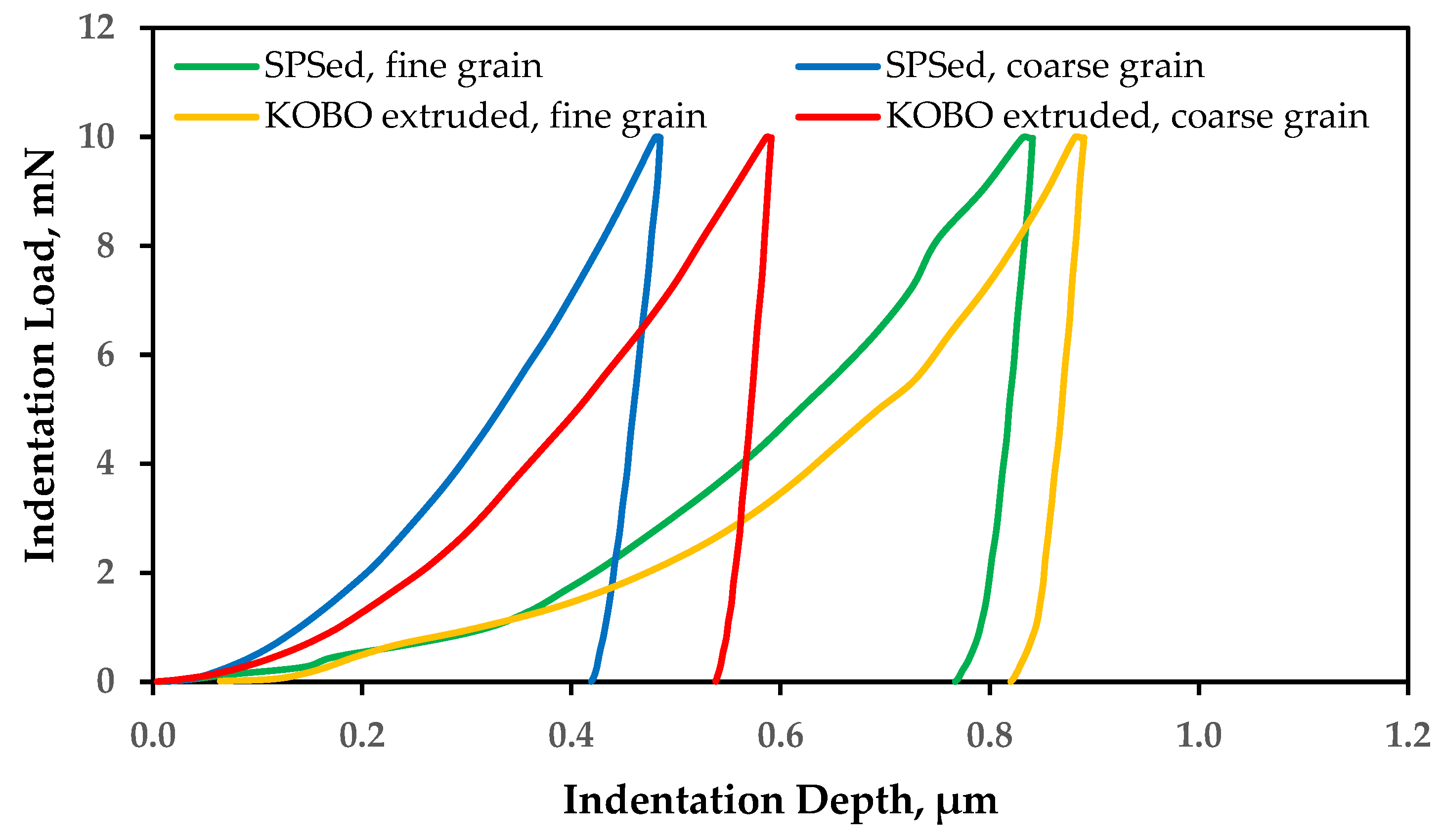
- Based on the strain gradient analysis of the nanoindentation of separate grains, the total dislocation density was evaluated. A drop in the dislocation density together with a decrease in the grain size was highlighted owing to dynamic recrystallization processes.
Author Contributions
Funding
Institutional Review Board Statement
Informed Consent Statement
Data Availability Statement
Acknowledgments
Conflicts of Interest
References
- Whittaker, D.; Garbiec, D.; Schurr, J.; Chaves, H. Euro PM2019: Novel process developments highlight new opportunities for PM. Powder Metall. Rev. 2020, 9, 77–86. [Google Scholar]
- Kang, L.M.; Cai, Y.J.; Luo, X.C.; Li, Z.J.; Liu, X.B.; Wang, Z.; Li, Y.Y.; Yang, C. Bimorphic microstructure in Ti-6Al-4V alloy manipulated by spark plasma sintering and in-situ press forging. Scr. Mater. 2021, 193, 43–48. [Google Scholar] [CrossRef]
- Soares, E.; Bouchonneau, N.; Alves, E.; Alves, K.; Araújo Filho, O.; Mesguich, D.; Chevallier, G.; Laurent, C.; Estournès, C. Microstructure and Mechanical Properties of AA7075 Aluminum Alloy Fabricated by Spark Plasma Sintering (SPS). Materials 2021, 14, 430. [Google Scholar] [CrossRef] [PubMed]
- Zadra, M.; Casari, F.; Girardini, L.; Molinari, A. Spark plasma sintering of pure aluminium powder: Mechanical properties and fracture analysis. Powder Metall. 2007, 50, 40–45. [Google Scholar] [CrossRef]
- Garbiec, D.; Siwak, P. Study on microstructure and mechanical properties of spark plasma sintered Alumix 431 powder. Powder Metall. 2016, 59, 242–248. [Google Scholar] [CrossRef]
- Al-Furjan, M.S.H.; Hajmohammad, M.H.; Shen, X.; Rajak, D.K.; Kolahchi, R. Evaluation of tensile strength and elastic modulus of 7075-T6 aluminum alloy by adding SiC reinforcing particles using vortex casting method. J. Alloy. Compd. 2021, 886, 161261. [Google Scholar] [CrossRef]
- Moghaddam, M.; Zarei-Hanzaki, A.; Pishbin, M.H.; Shafieizad, A.H.; Oliveira, V.B. Characterization of the microstructure, texture and mechanical properties of 7075 aluminum alloy in early stage of severe plastic deformation. Mater. Charact. 2016, 119, 137–147. [Google Scholar] [CrossRef]
- Segal, V.M. Severe plastic deformation: Simple shear versus pure shear. Mater. Sci. Eng. A 2002, 338, 331–344. [Google Scholar] [CrossRef]
- Ma, Z.Y. Friction Stir Processing Technology: A Review. Metall. Mater. Trans. A 2008, 39, 642–658. [Google Scholar] [CrossRef]
- Beygelzimer, Y.; Varyukhin, V.; Synkov, S.; Orlov, D. Useful properties of twist extrusion. Mater. Sci. Eng. A 2009, 503, 14–17. [Google Scholar] [CrossRef] [Green Version]
- Bazarnik, P.; Kurzydłowski, K.J.; Lewandowska, M. Mechanical behaviour of ultrafine grained Al-Mg alloys obtained by different processing routes. Arch. Metall. Mater. 2012, 57, 869–876. [Google Scholar] [CrossRef] [Green Version]
- Korbel, A.; Pieła, K.; Ostachowski, P.; Łagoda, M.; Błaż, L.; Bochniak, W.; Pawlyta, M. Structural phenomena induced in the course of and post low-temperature KOBO extrusion of AA6013 aluminum alloy. Mater. Sci. Eng. A 2018, 710, 349–358. [Google Scholar] [CrossRef]
- Korbel, A.; Bochniak, W.; Borowski, J.; Błaż, L.; Ostachowski, P.; Łagoda, M. Anomalies in precipitation hardening process of 7075 aluminum alloy extruded by KOBO method. J. Mater. Process. Technol. 2015, 216, 160–168. [Google Scholar] [CrossRef]
- Pieła, K.; Błaz, L.; Jaskowski, M. Effects of Extrusion Parameters by KoBo Method on the Mechanical Properties and Microstructure of Aluminum. Arch. Metall. Mater. 2013, 58, 683–689. [Google Scholar] [CrossRef] [Green Version]
- Garbiec, D.; Leshchynsky, V.; García-Junceda, A.; Heyduk, F. Association Spark Plasma Sintering and KOBO Extrusion Routes for Aluminum Matrix Composite Profiles Manufacturing. In Proceedings of the Euro PM2019 Congress & Exhibition, European Powder Metallurgy Association, Maastricht, The Netherlands, 13 October 2019. [Google Scholar]
- Standard Test Methods for Tension Testing of Metallic Materials; ASTM International: West Conshohocken, PA, USA, 2021.
- Tian, W.; Li, S.; Liu, J.; Yu, M.; Du, Y. Preparation of bimodal grain size 7075 aviation aluminum alloys and their corrosion properties. Chin. J. Aeronaut. 2017, 30, 1777–1788. [Google Scholar] [CrossRef]
- Queudet, H.; Lemonnier, S.; Barraud, E.; Guyon, J.; Ghanbaja, J.; Allain, N.; Gaffet, E. One-step consolidation and precipitation hardening of an ultrafine-grained Al-Zn-Mg alloy powder by Spark Plasma Sintering. Mater. Sci. Eng. A 2017, 685, 227–234. [Google Scholar] [CrossRef]
- Song, X.; Liu, X.; Zhang, J. Neck Formation and Self-Adjusting Mechanism of Neck Growth of Conducting Powders in Spark Plasma Sintering. J. Am. Ceram. Soc. 2006, 89, 494–500. [Google Scholar] [CrossRef]
- Sadeghi, B.; Cavaliere, P.; Shamanian, M.; Sanayei, M.; Szpunar, J.A.; Nosko, M. Electron backscattered diffraction analysis of friction stir processed nanocomposites produced via spark plasma sintering. J. Micro 2018, 271, 145–163. [Google Scholar] [CrossRef] [PubMed]
- Lin, Y.C.; Xiao, Y.-W.; Jiang, Y.-Q.; Pang, G.-D.; Li, H.-B.; Zhang, X.-Y.; Zhou, K.-C. Spheroidization and dynamic recrystallization mechanisms of Ti-55511 alloy with bimodal microstructures during hot compression in α+β region. Mater. Sci. Eng. A 2020, 782, 139282. [Google Scholar] [CrossRef]
- Tamimi, S.; Sivaswamy, G.; Pirgazi, H.; Amirkhiz, B.S.; Moturu, S.; Siddiq, M.A.; Kockelmann, W.; Blackwell, P. A new route for developing ultrafine-grained Al alloy strips using repetitive bending under tension. Mater. Des. 2021, 206, 109750. [Google Scholar] [CrossRef]
- Moon, C.; Thuillier, S.; Lee, J.; Lee, M.-G. Mechanical properties of solution heat treated Al-Zn-Mg-Cu (7075) alloy under different cooling conditions: Analysis with full field measurement and finite element modeling. J. Alloys Compd. 2021, 856, 158180. [Google Scholar] [CrossRef]
- Zhu, X.; Cao, G.; Liu, J.; Zhao, K.; An, L. Enhanced strength and ductility synergy in aluminum composite with heterogeneous structure. Sci. Eng. A 2020, 787, 139431. [Google Scholar] [CrossRef]
- Wu, X.; Zhu, Y. Heterogeneous materials: A new class of materials with unprecedented mechanical properties. Mater. Res. Lett. 2017, 5, 527–532. [Google Scholar] [CrossRef]
- Yoo, Y.S.J.; Lim, H.; Emery, J.; Kacher, J. Relating microstructure to defect behavior in AA6061 using a combined computational and multiscale electron microscopy approach. Acta Mater. 2019, 174, 81–91. [Google Scholar] [CrossRef]
- Bochniak, W.; Korbel, A.; Ostachowski, P.; Łagoda, M. Plastic flow of metals under cyclic change of deformation path conditions. Arch. Civil Mech. Eng. 2018, 18, 679–686. [Google Scholar] [CrossRef]
- Huang, X.; Kamikawa, N.; Hansen, N. Strengthening mechanisms in nanostructured aluminum. Mater. Sci. Eng. A 2008, 483–484, 102–104. [Google Scholar] [CrossRef]
- Hansen, N. Hall–Petch relation and boundary strengthening. Scr. Mater. 2004, 51, 801–806. [Google Scholar] [CrossRef]
- Byon, S.M.; Lee, Y. Deformation analysis of micro-sized material using strain gradient plasticity. J. Mech. Sci. Technol. 2006, 20, 621–633. [Google Scholar] [CrossRef]
- Fleck, N.A.; Muller, G.M.; Ashby, M.F.; Hutchinson, J.W. Strain gradient plasticity: Theory and experiment. Acta Metall. Mater. 1994, 42, 475–487. [Google Scholar] [CrossRef]
- Zhang, J.; Wang, B.; Wang, H. Geometrically necessary dislocations distribution in face-centred cubic alloy with varied grain size. Mater. Charact. 2020, 162, 110205. [Google Scholar] [CrossRef]
- Seyed Salehi, M.; Anjabin, N.; Kim, H.S. Study of Geometrically Necessary Dislocations of a Partially Recrystallized Aluminum Alloy Using 2D EBSD. Microsc. Microanal. 2019, 25, 656–663. [Google Scholar] [CrossRef] [PubMed]
- Liu, D.; He, Y.; Tang, X.; Ding, H.; Hu, P.; Cao, P. Size effects in the torsion of microscale copper wires: Experiment and analysis. Scr. Mater. 2012, 66, 406–409. [Google Scholar] [CrossRef]
- Nix, W.D.; Gao, H. Indentation size effects in crystalline materials: A law for strain gradient plasticity. J. Mech. Phys. Solids 1998, 46, 411–425. [Google Scholar] [CrossRef]
- Tabor, D. The Hardness of Metals; Clarendon Press: Oxford, UK, 1951. [Google Scholar]
- Nabarro, F.R.N.; Shrivastava, S.; Luyckx, S.B. The size effect in microindentation. Philos. Mag. 2006, 86, 4173–4180. [Google Scholar] [CrossRef]


| Al | Cu | Mg | Zn | Sn |
|---|---|---|---|---|
| Balance | 1.80 | 2.80 | 6.40 | 0.29 |
| Element | Atomic % | |||
|---|---|---|---|---|
| # 1 | # 2 | # 3 | # 4 | |
| Mg | 02.47 | 02.68 | 02.68 | 03.38 |
| Al | 88.22 | 78.86 | 78.86 | 86.85 |
| Fe | 00.61 | 00.45 | 00.45 | 00.00 |
| Co | 00.00 | 00.18 | 00.18 | 00.24 |
| Cu | 01.09 | 07.70 | 07.70 | 00.96 |
| Zn | 07.57 | 10.11 | 10.11 | 08.54 |
| Element | Atomic % | |||
|---|---|---|---|---|
| # 1 | # 2 | # 3 | # 4 | |
| Mg | 12.25 | 15.09 | 24.03 | 09.23 |
| Al | 67.83 | 66.81 | 58.35 | 84.07 |
| Si | 00.00 | 00.61 | 01.54 | 00.30 |
| Cu | 04.84 | 03.45 | 03.27 | 00.00 |
| Zn | 14.57 | 10.63 | 08.16 | 04.86 |
| Sn | 00.49 | 03.38 | 04.62 | 01.50 |
| Parameter, Unit | SPS | KOBO Longitudinal Cross-Section | KOBO Transverse Cross-Section | |||
|---|---|---|---|---|---|---|
| Coarse Grain | Fine Grain | Coarse Grain | Fine Grain | Coarse Grain | Fine Grain | |
| Density, g/cm3 | 2.78 ± 0.01 | 2.80 ± 0.01 | ||||
| Microhardness, MPa | 1440 ± 40 | 980 ± 20 | - | |||
| Yield tensile strength, MPa | 345 ± 15 | 277 ± 18 | ||||
| Ultimate tensile strength, MPa | 345 ± 15 | 422 ± 14 | ||||
| Total elongation, % | 2.0 ± 0.3 | 33.2 ± 2.5 | ||||
| Compressive strength, MPa | 618 ± 4 | 464 ± 32 | ||||
| Nanohardness, MPa | 1433 | 439 | 1021 | 356 | 944 | 539 |
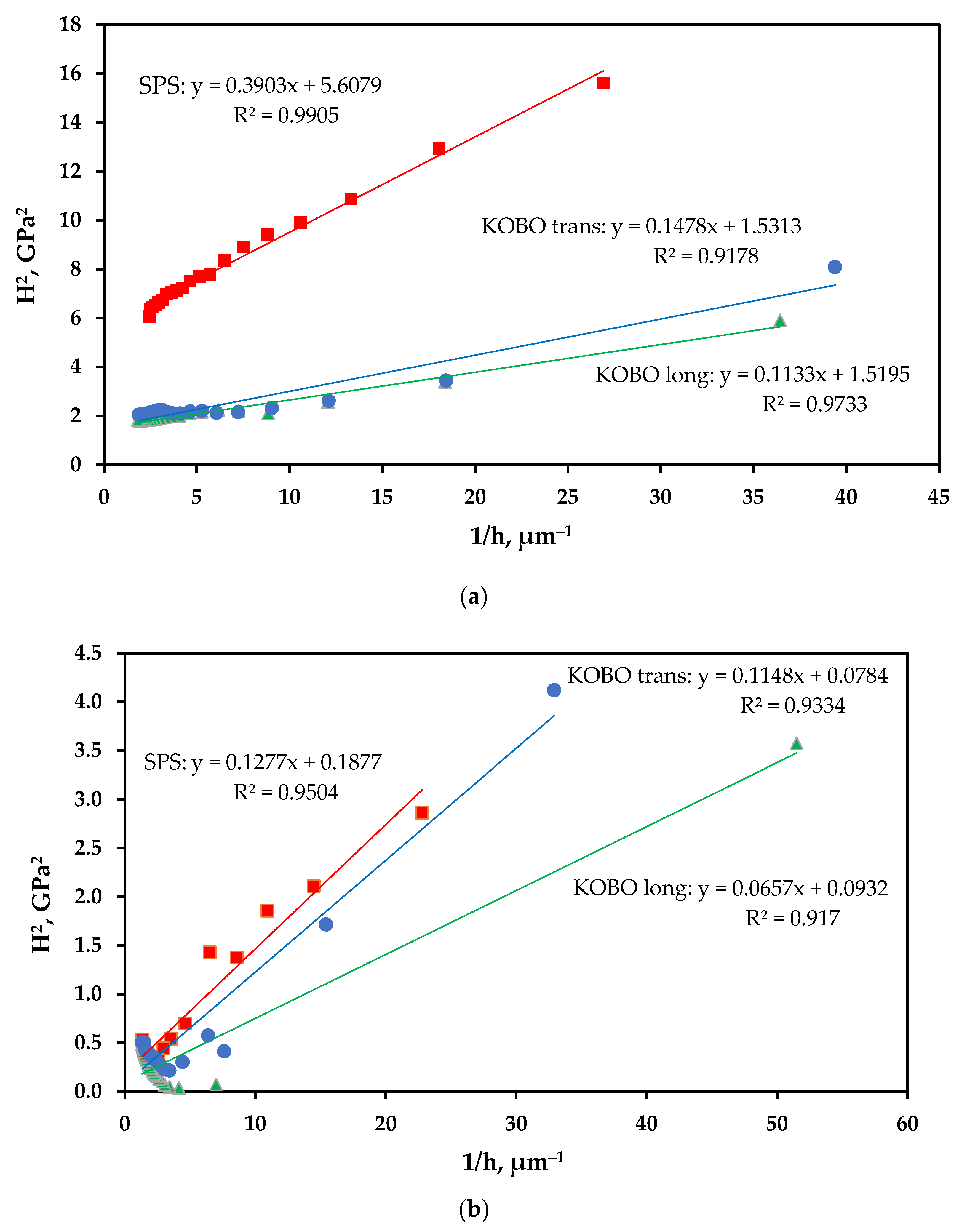
| Intrinsic hardness, H0, GPa | 2.370 | 0.434 | 1.230 | 0.305 | 1.240 | 0.282 |
| Intrinsic length, h*, μm | 0.0696 | 0.6792 | 0.0746 | 0.7045 | 0.0966 | 1.4351 |
| Linear simulation veracity, R2 | 0.9905 | 0.9504 | 0.9733 | 0.9170 | 0.9178 | 0.9334 |
| Nanoindentation stochastically stored dislocation density | 7.34 × 10¹⁵ | 2.46 × 10¹⁴ | 1.98 × 10¹⁵ | 1.22 × 10¹⁴ | 2.01 × 10¹⁵ | 1.04 × 10¹⁴ |
Publisher’s Note: MDPI stays neutral with regard to jurisdictional claims in published maps and institutional affiliations. |
© 2021 by the authors. Licensee MDPI, Basel, Switzerland. This article is an open access article distributed under the terms and conditions of the Creative Commons Attribution (CC BY) license (https://creativecommons.org/licenses/by/4.0/).
Share and Cite
Garbiec, D.; Leshchynsky, V.; García-Junceda, A.; Swadźba, R.; Siwak, P.; Adamek, G.; Radwański, K. Microstructure and Mechanical Properties of Spark Plasma Sintered and Severely Deformed AA7075 Alloy. Metals 2021, 11, 1433. https://doi.org/10.3390/met11091433
Garbiec D, Leshchynsky V, García-Junceda A, Swadźba R, Siwak P, Adamek G, Radwański K. Microstructure and Mechanical Properties of Spark Plasma Sintered and Severely Deformed AA7075 Alloy. Metals. 2021; 11(9):1433. https://doi.org/10.3390/met11091433
Chicago/Turabian StyleGarbiec, Dariusz, Volf Leshchynsky, Andrea García-Junceda, Radosław Swadźba, Piotr Siwak, Grzegorz Adamek, and Krzysztof Radwański. 2021. "Microstructure and Mechanical Properties of Spark Plasma Sintered and Severely Deformed AA7075 Alloy" Metals 11, no. 9: 1433. https://doi.org/10.3390/met11091433
APA StyleGarbiec, D., Leshchynsky, V., García-Junceda, A., Swadźba, R., Siwak, P., Adamek, G., & Radwański, K. (2021). Microstructure and Mechanical Properties of Spark Plasma Sintered and Severely Deformed AA7075 Alloy. Metals, 11(9), 1433. https://doi.org/10.3390/met11091433