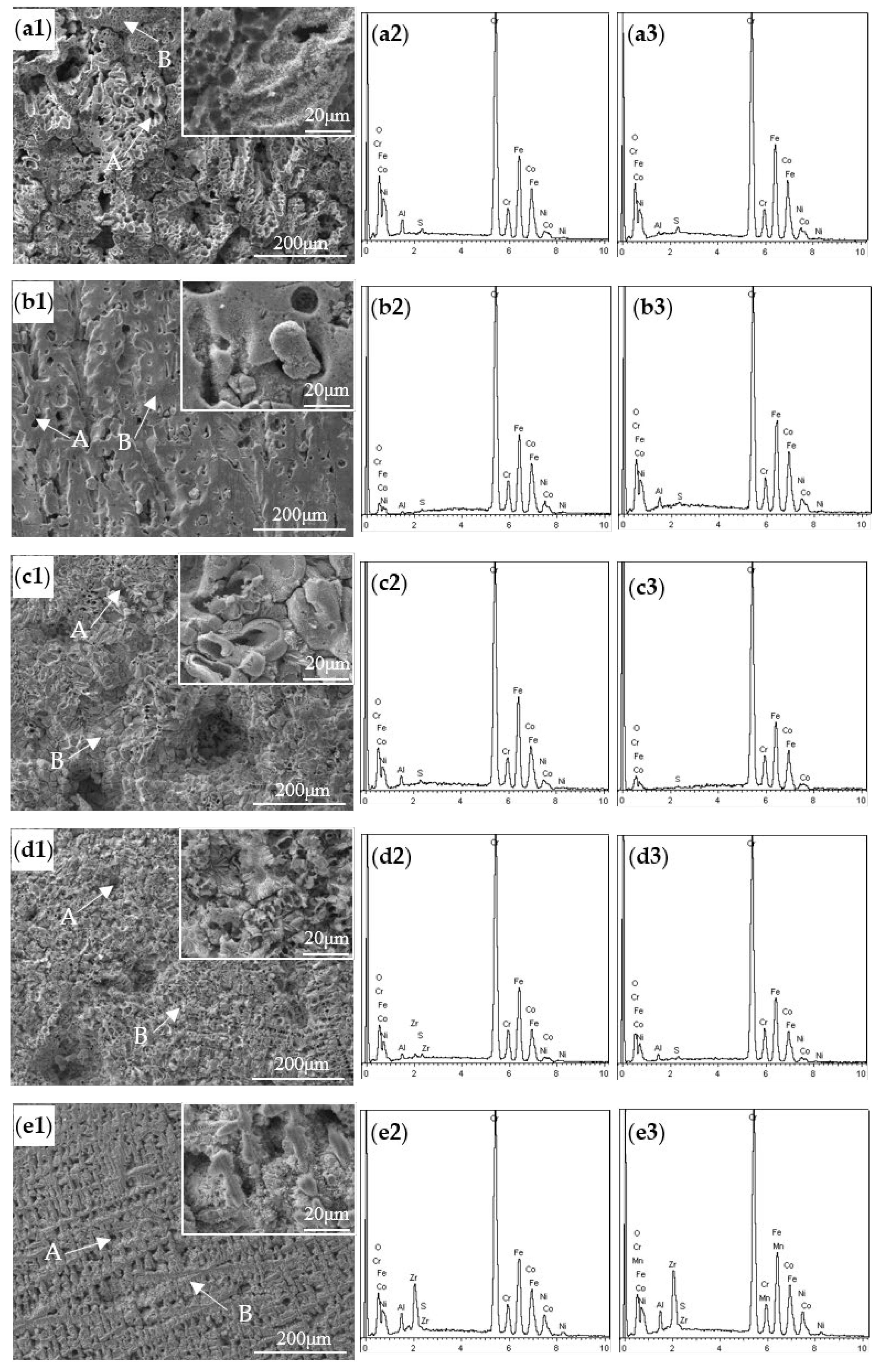
The corroded surface morphologies and the corresponding EDS spectra of the as-cast AlCoCrFeNiZr
x alloys in 0.5 M H
2SO
4 solution for the 0–192 h immersion tests at 25 °C are shown in
Figure 2. It can be seen from
Figure 2 that the main corrosion types of the AlCoCrFeNiZr
x alloys were general and intergranular corrosion, which is related to the microstructure of the AlCoCrFeNiZr
x alloys and the different dissolution characteristic in the corroded surface of the alloys relevant to the different phase structure and its chemical inhomogeneity [
24,
28].
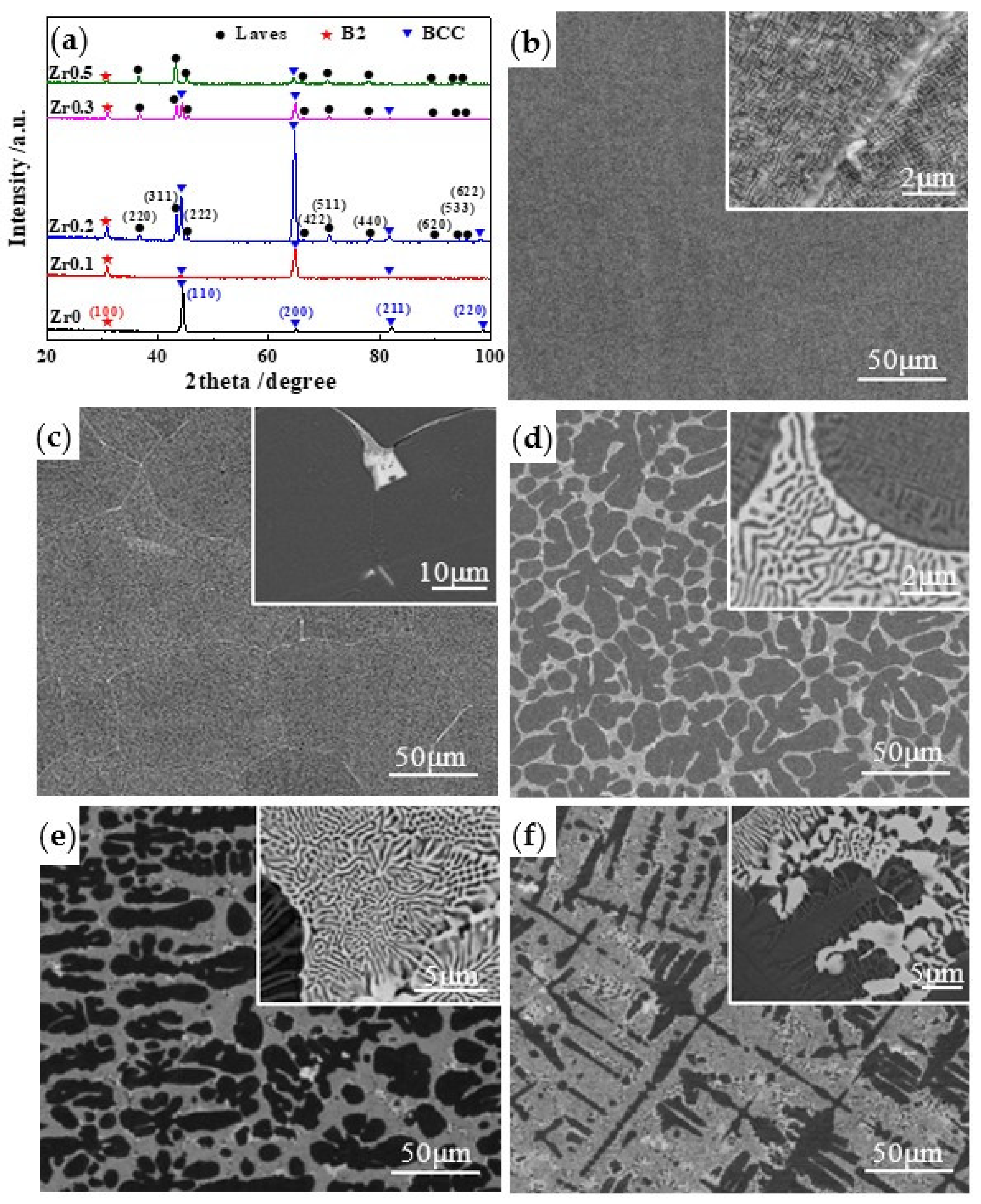
Figure 3 shows the XRD patterns and the typical SEM micrographs of the as-cast AlCoCrFeNiZr
x alloys (
x = 0, 0.1, 0.2, 0.3, and 0.5). From
Figure 3a,b, it can be seen that the Zr0 alloys were a uniform solid solution with a modulated plate structure composed of an Fe- and Cr-rich BCC phase (the bright phase in the enlarged image in
Figure 3b) and an Al- and Ni-rich ordered (B2) BCC phase (the dark phase in the enlarged image in
Figure 3b), which were formed by a spinodal decomposition mechanism [
18,
37,
38]. Moreover, it is also seen from
Figure 3b that the detailed microstructures of the Zr0 alloys can only be identified at a large enough magnification, and the same result was confirmed by Shi et al., in that the disordered and ordered BCC phases in the FCC matrix of Al
xCoCrFeNi HEAs cannot be separated via the BSE/EDS observation due to their fine grain size [
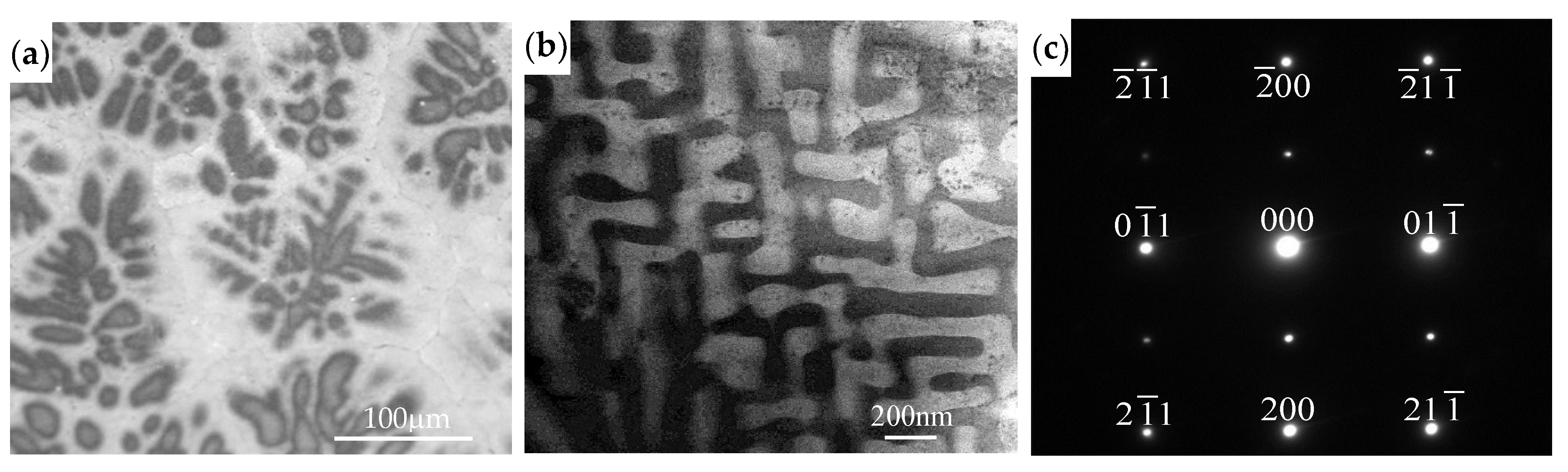
16]. However, the near-equiaxed dendritic microstructure of the Zr0 alloys can be observed by OM in
Figure 4a, and the black dendritic regions and the bright interdendritic regions can be seen clearly, which largely results from the elemental segregation between the dendritic and interdendritic regions [
39]. Xiang et al. [
16] also revealed that the most negative mixing enthalpy between Al and Ni was responsible for the formation of the Al- and Ni-rich ordered B2 matrix in the (Al, Ni)-rich dendritic and (Fe, Cr)-rich interdendritic regions of the as-cast AlCoCrFeNiSi0.1 alloy, and the periodic and coherent microstructure composed of the (Fe, Cr)-rich A2 phase and (Al, Ni)-rich B2 phase could be observed in both the (Al, Ni)-rich dendrite and the (Fe, Cr)-rich interdendrite. TEM was used to investigate the Zr0 alloys, and the bright-field TEM image and the corresponding selected area electron diffraction pattern along the [
11] zone axis are shown in
Figure 3b,c.
Figure 3c reveals the superlattice reflections, confirming the existence of an ordered B2 phase. Therefore, the bright phase in
Figure 3b is the Al- and Ni-rich ordered B2 phase, while the dark phase is the Fe- and Cr-rich disordered BCC phase, which is in agreement with the results of many previous studies [
18,
40,
41]. Due to the formation of the Zr
X2 (
X = Co or Ni) Laves phase with the space group Fd3m (no. 227) [
32], the microstructures of the AlCoCrFeNiZr
x alloys (
x = 0.1, 0.2, 0.3, and 0.5) were composed of an Fe- and Cr-rich BCC phase (the gray phase in the enlarged image in
Figure 3d–f), an Al- and Ni-rich B2 phase (the black phase in the enlarged image in
Figure 3d–f), and a Zr- and Ni-rich Laves phase (the bright phase in the enlarged image in
Figure 3c–f). It was reported by Qiu et al. [
18] that an Al0.9CoCrFeNi alloy comprised a combination of FCC, Fe-Cr-rich BCC, and Al-Ni-rich B2 phases, and an Al0.9CoCrFeNiTi0.5 alloy consisted of an Fe-Cr-rich BCC phase, an Al-Ni-rich B2 phase, and an Fe–Cr sigma phase. Though Ti has similar physical features to Zr, i.e., both elements have a hexagonal close-packed (HCP) crystal structure, a high melting temperature, and good corrosion resistance, the introduction of the Laves phase in AlCoCrFeNiZr
x (
x = 0.1, 0.2, 0.3, and 0.5) alloys instead of an Fe-Cr sigma phase is mainly attributed to the difference between the radius of the Zr atom and the other constituent atoms, as well as the large negative mixing enthalpy between the constituent atomic pairs [
32]. Moazzen et al. [
39] calculated the Gibbs free energy for the formation of all possible binary intermetallic compounds in the FeCoCrNi and FeCoCrNiZr0.4 systems at 298 K, and they also revealed that the greater negative Gibbs free energy in the formation of the intermetallic compounds containing zirconium than that of the other intermetallic compounds was due to the large difference in the atomic radius and electronegativity of Zr with the other alloying elements. The Laves phase was preferentially formed along the grain boundary in the Zr0.1 alloy (
Figure 3c), and the volume fraction of the Laves phase located in the interdendritic zone increased with the Zr content, which became the main phase when the Zr content was over 0.3 mol (
Figure 3e,f).
Table 2 shows the EDS results of the dendritic and interdendritic zones of the AlCoCrFeNiZr
x alloys (
x = 0, 0.1, 0.2, 0.3, and 0.5), and it can be easily seen from
Table 2 that the bright interdendritic regions of the Zr0 alloys in
Figure 4a were rich in Cr and Fe, while the dendritic regions were enriched with Al and Ni, and Co was almost uniformly distributed in these two distinct regions, both of which are composed of an (Fe, Cr)-rich BCC phase and an (Al, Ni)-rich B2 phase; the same results were also reported by Xiang et al. [
27]. Moreover, it can also be seen from
Table 2 that the markedly different metal concentrations of Cr and Zr were found in the interdendritic and dendritic areas of the AlCoCrFeNiZr
x (
x = 0.1, 0.2, 0.3, and 0.5) alloys, and Zr additions were almost segregated along the grain boundary in the Zr0.1 alloys and enriched in the Laves phase of the Zr0.2, Zr0.3, and Zr0.5 alloys. Perhaps, due to the formation of the Zr
X2 (
X = Co or Ni) Laves phase in the interdendritic regions, it is difficult to detect Zr elements in the (Al, Ni)-rich dendritic regions. It is well known that, due to the formation of protective chromium oxide-based passive films on the surfaces, Fe-Cr and Fe-Cr-Ni stainless steels have good general corrosion resistance and pitting corrosion resistance in different corrosion media, and the role of Cr in protecting HEAs is thought to be similar to its protecting role in stainless steels [
13]. Kao et al. [
14] reported that, due to the poor protective capabilities of an Al oxide-based film on the surface of Al-containing CoCrFeNi HEAs, Al additions were detrimental to the corrosion resistance of the Al
xCoCrFeNi alloy system in sulfuric acid solution, and Ni could easily combine with Al to form an Al- and Ni-rich B2 phase, which might deteriorate the corrosion resistance of Ni-containing Al
xCoCrFeNi alloys. Based on these results, it can be concluded that the selective corrosion of the Al- and Ni-rich, Cr-depleted B2 phases in the AlCoCrFeNiZr
x (
x = 0, 0.1, 0.2, 0.3, and 0.5) alloys is mainly attributed to the large bonding in Al and Ni [
16], which tends to readily react with (OH)
− and (SO
4)
2− to form less protective Al and Ni complexes, such as Al
2O
3, Al(OH)
3, and NiO, and dissolve in 0.5 M H
2SO
4 solution [
14]. Accordingly, the seriously corroded surface in
Figure 2(a1) was mainly caused by the selective dissolution of Al and Ni in the Al- and Ni-rich ordered B2 phase in the Zr0 alloys, and similar phenomena have been reported by other researchers [
14,
15,
16,
17,
18,
26,
27,
29]. It has been mentioned before that both the (Al, Ni)-rich dendrite and the (Fe, Cr)-rich interdendrite of Zr0 alloys have a periodic and coherent microstructure composed of an (Fe, Cr)-rich A2 phase and an (Al, Ni)-rich B2 phase, inferring that the Al- and Ni-rich, Cr-depleted B2 phases in both the dendrite and interdendrite are caused by a severe galvanic corrosion attack, where an Al- and Ni-rich, Cr-depleted B2 phase is the anode coupled with the Fe-Cr-rich BCC phase, which can be also confirmed by
Table 3.
Table 3 shows EDS analyses on the marked regions in the corroded surfaces of the AlCoCrFeNiZr
x (
x = 0, 0.1, 0.2, 0.3, and 0.5) alloys, where regions A and B represent the seriously and slightly corroded surfaces, respectively. From
Table 3, it can be seen that both regions A and B were enriched with Cr, Fe, and O but depleted of Al and Ni, which means either the dendrite or the interdendrite was greatly attacked by galvanic corrosion during the immersion tests in 0.5 M H
2SO
4 solution. As seen in
Table 2 and
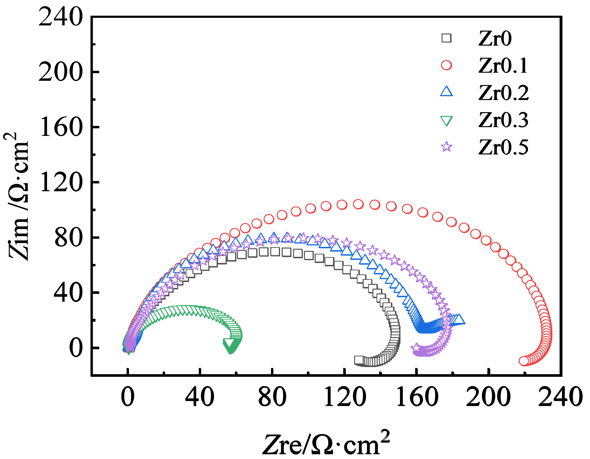
Figure 3c, almost 0.1 mol of the Zr addition preferentially segregated along the grain boundary of the Zr0.1 alloys during the period of solidification. Due to the good corrosion resistance of the Laves phase with more than 85 wt % Zr or nearly pure Zr, the galvanic corrosion potential difference between the grain boundary and the grain itself became small, and the corrosion of the grain boundary was almost inhibited, that is, the addition of 0.1 mol Zr resulted in isolated grains surrounded by a high Zr content of the Laves phase or pure Zr in the grain boundary, which prevented or retarded the corrosion process of the Zr0.1 alloys in 0.5 M H
2SO
4 solution. In other words, the dissolution of the Al- and Ni-rich B2 phase coupled with the Fe-Cr-rich BCC phase was restricted within the grain, and due to the grain refinement caused by the Zr addition compared with the Zr0 alloys (see
Figure 3c and
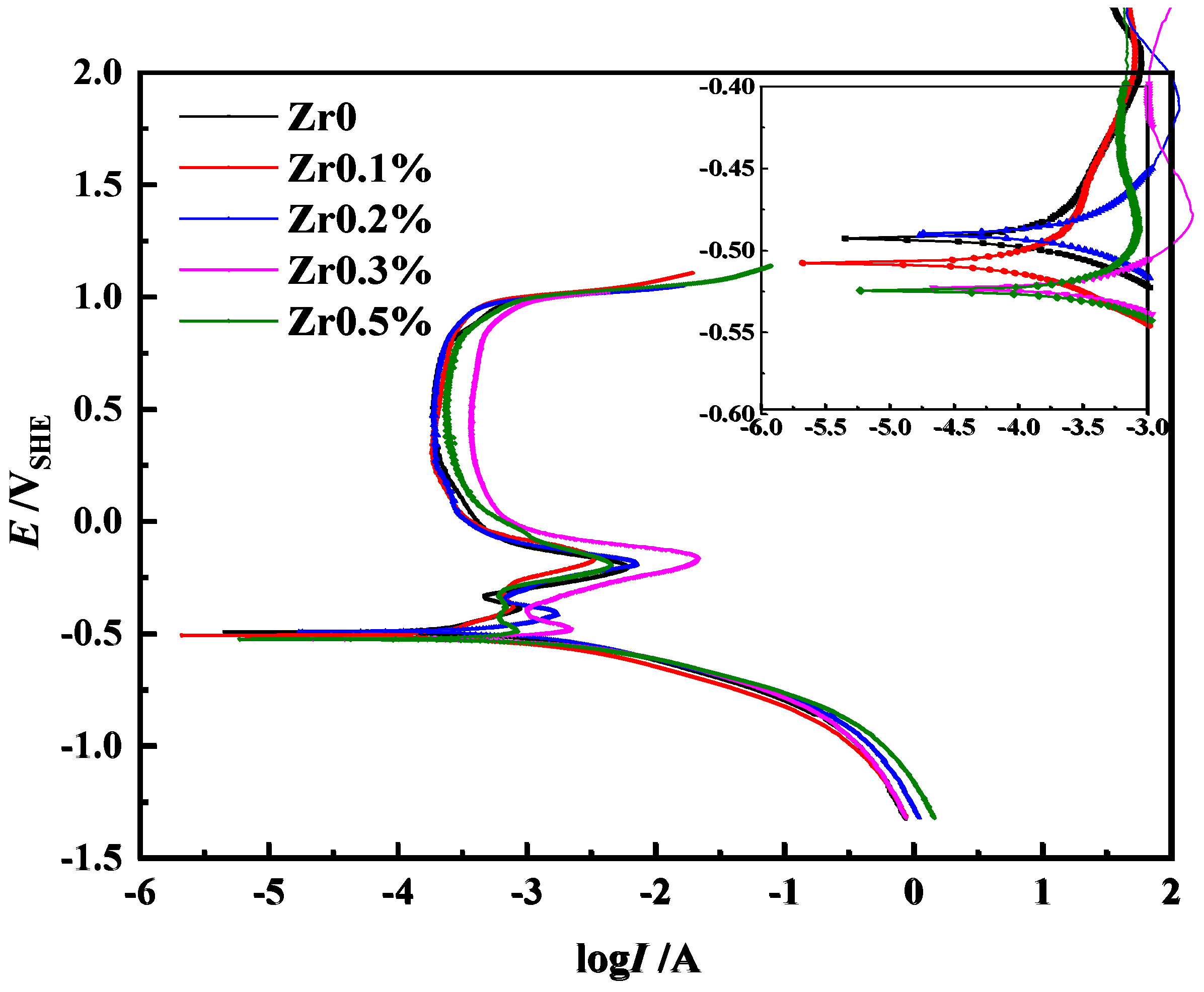
Figure 4a), a lot of grain boundaries with good corrosion resistance existed in the Zr0.1 alloys, and the corrosion rate of the grain was retarded. Therefore, the Zr0.1 alloys had the smallest corrosion rate (
Figure 1b) and good galvanic corrosion resistance.
Table 3 also shows a seriously corroded surface with higher Cr and lower Al and Ni contents, a slightly corroded surface with higher Cr and lower Al and Ni contents, and a slightly corroded surface with a relatively high Cr, Al, and Ni content, revealing the corrosion process by the dissolution of the (Al, Ni)-rich and Cr-depleted B2 phase; this can also be confirmed by the small amount of isolated corroded pits and the large area of the relatively less corroded flat surface in
Figure 2(b1), which means that the dissolution of the B2 phase was inhibited within the isolated grains in the Zr0.1 alloys. Since the interdendritic and dendritic regions have markedly different chemical compositions, both selective corrosion and general corrosion were found to appear in the Zr0.2, Zr0.3, and Zr0.5 alloys with increasing Zr content, as it can be observed in
Figure 2(c1–e1). From the enlarged images in
Figure 3d–f, it can be seen that with the increase in the Zr content from 0.1 to 0.5 mol, the width of the periodic structure consisting of the (Fe, Cr)-rich BCC phase and (Al, Ni)-rich B2 phase significantly became thicker, especially close to the interfaces of the Laves phase in the Zr0.2 and Zr0.3 alloys, while the periodic structure was refined again with the Zr content further increased to 0.5 mol. From
Figure 2, it can be clearly seen that the general corrosion and intergranular corrosion of the Zr0.2 and Zr0.3 alloys were severe for the “tubular coral reef” morphology and their relatively larger and deeper pits, which mostly resulted from the dissolution of the thicker (Al, Ni)-rich and Cr-depleted B2 phase in these two alloys. Additionally, compared to the corrosion morphology of the “pine needles” present on the surface of the Zr0.5 alloys, the obvious “tubular coral reef” morphology indicates that the Zr0.3 alloys with the largest width of the periodic structure or the maximum volume fraction of the (Al, Ni)-rich and Cr-depleted B2 phase among the AlCoCrFeNiZr
x (
x = 0, 0.1, 0.2, 0.3, and 0.5) alloys suffered the most severe corrosion in 0.5 M H
2SO
4 solution. It can be easily found that with an increasing Zr content, the Laves phase dramatically increased in the Zr0.2 alloys and became the main phase in the Zr0.3 and Zr0.5 alloys. For the Zr0.2, Zr0.3, and Zr0.5 alloys, the corroded surfaces seriously suffered from the galvanic corrosion existing in both the dendritic zone for an Al- and Ni-rich, Cr-depleted B2 phase as the anode coupled with the Fe-Cr-rich BCC phase and the interdendritic zone for an Al- and Ni-rich, Cr-depleted B2 phase as the anode coupled with the Zr-rich Laves phase. Moreover, it can be proposed based on
Table 2 that during the decline in the Zr content in the Laves phase, the resistance to general corrosion of the Zr0.2, Zr0.3, and Zr0.5 alloys compared to the Zr0.1 alloys slightly decreased, and the surfaces of the Zr0.2, Zr0.3, and Zr0.5 alloys were roughened by general corrosion.
Table 3 also reveals that both the severely and the slightly corroded surfaces were rich in Cr and lacked Al, Ni, and Zr compared with the chemical compositions of the Zr0.2, Zr0.3, and Zr0.5 alloys in
Table 2. These results are in accordance with research on the electrochemical behavior of multi-component amorphous and nanocrystalline Zr-based alloys in NaOH and H
2SO
4 solutions [
42]. Regarding the formation of a Zr-rich Laves phase and the maximum ratio of the Al- and Ni-rich, Cr-depleted B2 phase in the microstructures, the Zr0.3 alloys presented the heaviest volume loss and the worst corroded surfaces, as shown in
Figure 1 and
Figure 2(d1), respectively. As seen in
Figure 3f, the volume fraction of the Zr-rich Laves phase with relatively better galvanic corrosion resistance dramatically increases to more than 60% together with a decreased volume fraction of the Al- and Ni-rich, Cr-depleted B2 phase and the Fe–Cr-rich BCC phase to less than 40% in the Zr0.5 alloys. It is because the decrease of the Al- and Ni-rich, Cr-depleted B2 phase that the Zr0.5 alloys show the almost matchable volume loss and corrosion resistance to the Zr0.2 alloys and the smaller volume loss and better corrosion resistance than the Zr0.3 alloys.


