Article

The Microstructure and Property of a Titanium-Carbon Steel Clad Plate Prepared Using Explosive Welding

1
School of Material Science and Engineering, Xi’an Shiyou University, Xi’an 710065, China
2
Xi’an Key Laboratory of High Performance Oil and Gas Field Materials, Xi’an Shiyou University, Xi’an 710065, China
Metals 2022, 12(1), 129; https://doi.org/10.3390/met12010129
Submission received: 30 November 2021 / Revised: 19 December 2021 / Accepted: 30 December 2021 / Published: 10 January 2022
(This article belongs to the Special Issue Corrosion and Protection of Metallic Materials)

Abstract

:
The microstructure and properties of pure titanium (Ti)-carbon steel clad plate prepared using explosive welding were characterized. The bonding of the welding interface was inspected using C-scanning imaging technique. The microstructure and composition of the clad were characterized with optical microscopy and scanning electron microscopy. Mechanical and corrosion properties of the clad plate were investigated using tensile test, shearing test, and potentiodynamic polarization measurement. The results show that the pure titanium and carbon steel plate are joined successfully without visible defects. The interface wave is uniform. SEM observation and EDS analyses show that some melt blocks distribute at the interface waves vortices. Hardness testes results show that after heat treating, the hardness values in the titanium layer of the clad plate are similar to the original titanium plate, whereas the values at carbon steel layer increase from the interface to 300 μm away. Tensile and shearing test results indicate that the mechanical properties of the clad meet the requirements of ASTM B898 standard. Corrosion test shows that the Ecorr of the clad plate is more positive, and icorr is 1 order of magnitude lower compared to carbon steel material, suggesting that the corrosion resistance of clad plate is better than that of carbon steel material. These results suggest that the clad plate has good bonding quality and properties to meet the processing requirement and can be safely applicable in the petrochemical field.

1. Introduction

Titanium (Ti) and its alloy have excellent corrosion resistance, low density, high specific strength, and heat resistance; thus, they are widely used in the aviation, aerospace, and petrochemical industries. Especially, titanium exhibits excellent resistance to corrosion attack in many aggressive media and is deserving of close attention as a structural material in the design of chemical processing machinery. Thus, lots of equipment manufacturers in petrochemical industry pay more attention to titanium-based materials. However, the price of titanium materials is high, which increases product cost of the equipment [1,2,3]. It limits the wide application of titanium. One of the most common methods to reduce the production cost is to reduce titanium content in the equipment. Thus, the technique to produce a reliable joint of titanium-based material to other metals is of great importance. However, it is well known that the welding of titanium with other metals is difficult due to the formation of intermetallic compounds during welding. Lots of brittle Fe-Ti series intermetallic compounds would form with traditional welding method (such as fusion welding, diffusion bonding, and brazing methods). These brittle Fe-Ti intermetallic compounds weaken the joint strength [4,5,6]. The most effective method to join Ti with other metal is explosive welding, which can produce different clad materials such as titanium-steel clad materials, titanium-copper clad materials, and titanium-nickel clad materials [7,8,9]. Titanium-steel clad materials possess both titanium and steel advantages (high strength and toughness, reduce costs as well as high corrosion resistance). Thus, the demand for titanium-steel clad materials increases in pipes and vessels (such as tanks, piping, autoclaves, and heat exchangers) [10,11,12]. Recently, although the interface microstructure and mechanical properties of titanium clad materials have been investigated by some studies [10,11,12,13,14], few works have been carried out to investigate the corrosion performance of the titanium materials before and after explosive welding. As well, the microstructure and mechanical properties of this clad material still need further investigation. For this purpose, a clad plate of titanium and carbon steel was obtained using explosive welding. After welding, the microstructure, mechanical properties, and corrosion resistance of this clad material were investigated.

2. Experimental Procedure

2.1. Materials

Ti (ASME SB265 Gr1) plates in solution-annealed condition and carbon steel plates (ASME SA516 Gr70) in normalization condition were used for explosive welding. Their chemical compositions are listed in Table 1. Ti and carbon steel plates were prepared with the dimensions of 4 mm × 1500 mm × 1500 mm and 30 mm × 1500 mm × 1500 mm, respectively.

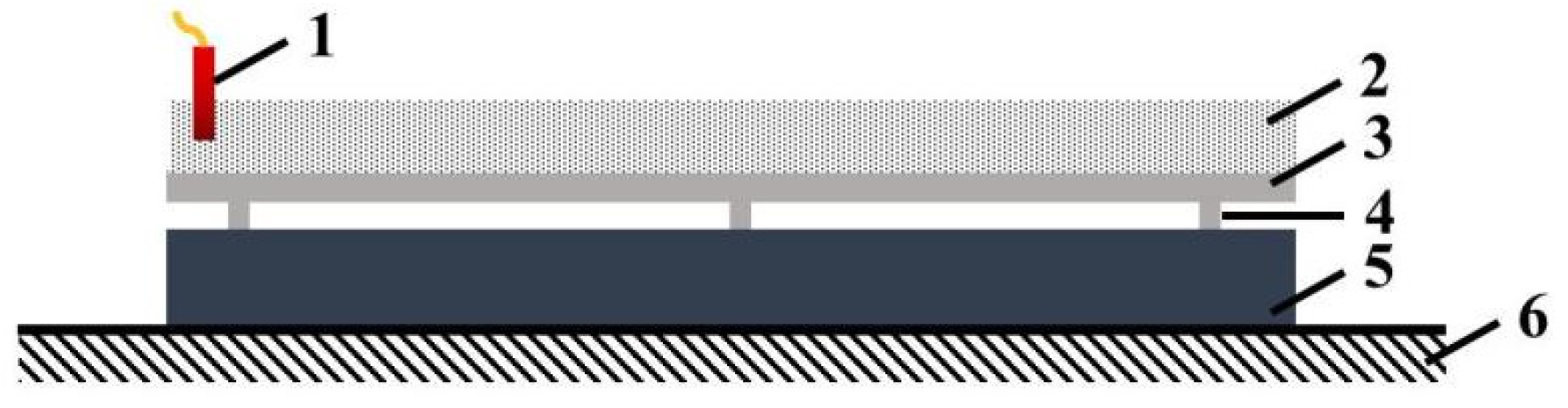
2.2. Explosive Welding Process

Parallel arrangement was employed for the experiment. Figure 1 shows the assemble scheme of explosive welding. The Ti and carbon steel plates were placed in the parallel direction. The spacers (made of pure titanium) were placed on the surface of the carbon steel base plate to support the Ti plate. The height of the spaces was about 8 mm. The ANFO explosive layer was spread on the surface of the cladding plate. In addition, the explosives were packed in the wooden box with the same dimension as the cladding plate. The thickness of the explosive was 20 mm, the density was 0.72 g/cm3, and the velocity was approximately 2140 m/s. Based on our previous research [15], the collision point velocity (Vcp) and dynamic collision angle (θ) were obtained. They were 2089 m/s and 14.8°, respectively. Thus, the Ti plate impact velocity (Vp) could be calculated by following Equation (1) with the Vcp and θ.
Vp = 2Vcp sin(θ/2)
Vp of the Ti plate reached 538 m/s. An electronic detonator was placed in the long edge of the Ti pate. By igniting the electronic detonator, the detonator initiated the explosives, and the Ti plate was accelerated to shock rapidly the carbon steel plate [16,17].

2.3. Specimen Characterization

Ultrasonic examination (UT) was employed to inspect the clad plates using OLYMPUS 5077 equipment [7]. During the UT process, the bonding interface image was obtained using ultrasonic C-scanning imaging technology. After that, the specimens were cut in the detonation direction. The cross-sections of specimens were ground with SiC sandpaper and polished with diamond paste. The carbon steel and clad plates were etched using the mixture of 3 mL hydrogen nitrate and 97 mL alcohol. The microstructure at the welding interface was observed using optical microscopy (Olympus GX51). Cross-sectional observation of the clad plate after explosive welding and their elemental analyses were conducted using a scanning electron microscopy (SEM, SSX-550) equipped with energy-dispersed X-ray microanalyzer (EDS).
Tow specimens for shearing test and one specimen for tensile test were prepared according to the ASTM B898 standard [18]. The tolerance value of the specimens sizes should meet the requirement of the standard. Shearing and tensile tests were carried out on a testing machine (DLY-10A) at room temperature. The shearing speed was 0.2 mm/min. A three-electrode system attached to an electrochemical workstation (CHI660E) was used for the electrochemical measurement. The original Ti material, carbon steel and the clad plate specimens were used as the working electrode, while the saturated calomel electrode and platinum electrode were used as reference electrode and counter electrode, respectively. The corrosive medium was 3.5 wt.% NaCl solution at room temperature. The polarization curve was scanned from −2.0 to 2.0 VSCE at a scan rate of 0.5 mV/s. The corrosion potential (Ecorr) and corrosion current density (icorr) for each specimen were obtained from the Tafel curve using CorrView software.

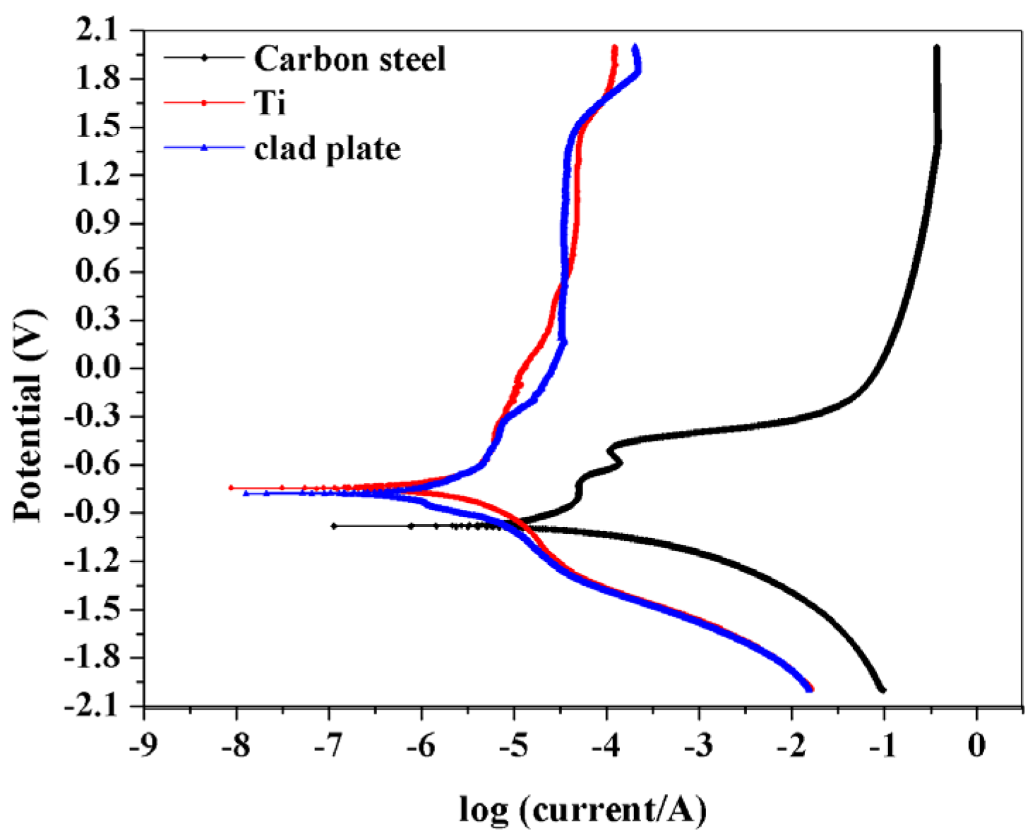
3. Results and Discussion

During the explosive welding process, sufficient joining impact pressure is produced at the interface, ensuring the successful preparation of the clad plate [14]. It could be seen that the Ti and carbon steel are tightly joined, and nonbounding defects are observed at the clad plate surface or side (shown in Figure 2a). During cladding, the high-speed collision produces large plastic at the interface of the metals, yielding the increase in the hardness values of the clad plate at both sides [4,10,11]. Thus, to remove the work-hardening effect [12], the Ti-carbon steel clad plates are generally annealed at 550–650 °C (atmosphere, holding 1 h), to release the residual stress produced during welding. After heat treating, the clad plate is inspected using the ultrasonic C-scanning imaging technology. The inspect results show that the bonding interface has the typical waves (Figure 2b). Obviously, the interface waves are uniform without any defect at the bounding interface, suggesting that the bounding interface is great. There are 7–8 waves in 1 cm length, also indicating that the bonding quantity of the clad plate is good [12,19]. Figure 2c shows the optical microstructure at the interface of clad plate. It shows that the typical wavy interface has been formed, and no visible defects such as pores or cracks are found. The reason is that during the drastic collision process, and the kinetic energy of Ti plate is partly transformed into potential energy, leading to the plastic deformation of both plates at the interface. In addition, it should be mentioned that some melt blocks in the interface wave vortices are also found.
To clearly observe the morphology of the bonding interface, SEM and EDS analyses are used (Figure 3). It can be seen that the Ti plate is joined tightly with carbon steel plate (Figure 3a). At a higher magnification (Figure 3b), no continuous defects are observed along the wavy interface. Only some small molten blokes are found to distribute in the wave vortices. The molten blocks are formed due to the dissipation of the whole kinetic energy at the interface. During the explosive welding, the Ti plate collides sharply the carbon steel plate, and most of kinetic energy dissipated at the interface results in the formation of wave. In addition, the rest kinetic energy dissipated at the bonding interface is transformed into thermal energy and led to the formation of molten blocks [20]. However, it can be seen from the images that these discontinuous melt blocks are packaged in the waves, and they do not weaken the bonding interface [4,10,11,13]. EDS analyses are shown in Figure 4. The chemical components of the Ti layer (square 002 in Figure 4a), carbon steel layer (square 004 in Figure 4a), and the melt block (square 003 in Figure 4a) are given in Figure 4b–d. As confirmed by the EDS analyses, square 002 consists of 99.22% Ti, 0.26% Fe, and 0.52% C (Figure 4b), which are almost identical to the composition of the original Ti plate. Square 004 is composed of 99.12% Fe, 0.78% C, and trace Ti, which also are similar to the composition of original carbon steel plate (Figure 4c). The presence of Ti element in square 004 might be caused by the contamination during polishing. EDS analysis of the molten block (square 003) is shown in Figure 4d. The result shows that both Ti and carbon steel are involved in the formation of molten block because of circular movement, the stirring of molten materials, and the mixing of both Ti and carbon steel materials. In addition, during the explosive welding, the temperature at the bonding interface exceeds the melting temperature of Ti and carbon steel in a short time. Thus, it could lead to the diffusion of the element across the interface [19,20,21]. However, Figure 2c and Figure 3a indicate that there is no diffusion layer across the interface. In order to clarify whether the element diffusion process is involved, line scanning is conducted about 200 mm across the interface. The results are shown in Figure 4e. The line scanning analyses show that the contents of Ti and Fe elements both have sharp transitions across the interface. It indicates that element diffusion process does not occur. The content of C element is much lower in carbon steel; thus, it can be hardly observed in the line scanning picture. In addition, Figure 5 shows the Ti and Fe elements mapping at a lower magnification (Figure 3a). The element mapping results indicate that the diffusion does not occur, consisting of the lining scanning results. In addition, the chemical composition in the molted block is almost the Fe element. The result are also in agreement with the EDS linear scanning analysis.
Vickers hardness tests are performed to inspect original Ti, carbon steel and the clad plate. The hardness values of original Ti and carbon steel are 127 and 163 HV, respectively. In addition, Figure 6 shows Vickers hardness variation with the different distances from the interface of the clad plate. At the titanium layer, the hardness value is 120 HV close to the interface. Towards the thickness center of the titanium layer, similar hardness values (122–135 HV) were measured at 50, 100, 150, 200, 250, 300, 350 and 500 μm to the interface. In addition, at the same distance in the carbon steel layer (0, 50, 100, 150, 200, 250, 300, 350 and 500 μm, hardness values are measured respectively, yielding the values of 212, 246, 233, 231, 215, 220, 209, 169 and 171 HV. Most of them are higher than original carbon steel. In general, due to the deformation of the plates resulting from the collision at high velocity, the hardness values near the joint interface of the clad plate should increase. After heat treating, the values of the clad plate would decrease to that of original materials. In this paper, the hardness values of titanium layer are similar to that of the original Ti material. It indicates that heat treatment releases residual stress at the titanium layer. However, at the layer of carbon steel, the increased hardness values are found from the interface to 300 μm away. Over 300 μm, the hardness values decrease and approach to that of the original carbon steel. It indicates that heat treatment could not completely release the residual stress at the carbon steel layer.
Figure 7 and Figure 8 show the results of shear and tensile tests to characterize mechanical properties of the clad plate, in which the shearing test is conducted to evaluate the bonding quality of the clad plate. The shearing strength (τb) values of two samples are 175 and 200 MPa, respectively (Figure 7). They are all higher than that of ASTM B898 standard requirement (τb ≥ 137.9 MPa is acceptable) [18]. Thus, the bonding quality of the clad plate meets the application requirement. In addition, the interfaces of the shearing specimens are uniform and wavy, consisting with the results of C-scanning (Figure 2b). The typical tensile curves, specimen and test result of the clad plate are shown in Figure 8a,b. The clad plate exhibits typical elastic deformation firstly and then plastic deformation (Figure 8a). The yield strength (Rp0.2) and ultimate tensile strength (Rm) of the clad plate are 344 and 524 MPa, respectively. In addition, the elongation (A) is 25%. Moreover, these values meet the requirement of ASTM B898 specification (Rp0.2 ≥ 260 MPa, Rm ≥ 485 MPa, A ≥ 17%). According to the recent research [21,22], the mechanical properties of the explosively welded clad plate would be mainly influenced by the component with a high strength. In addition, the explosive welding mainly influences the region adjacent to the clad plate interface whose thickness is no more than 300 μm. It means the tensile properties of the clad plate would be minor influenced by the interface microstructure change. Thus, the tensile strength of the clad plate is similar to that of carbon steel plate.
Although it is well known that titanium-based material has excellent corrosion resistance, a tremendous amount of heat and pressure released by explosives on the surface of the Ti plate during the explosive welding could decrease the corrosion resistance of titanium material. To investigate this, the corrosion performance of Ti materials before and after explosive welding is evaluated using polarization curves. Figure 9 shows the polarization curves of original Ti material, carbon steel and the clad plate. It can be seen that the carbon steel possesses active dissolution, and its anodic current density increases rapidly with the increase in anodic overpotential. The original Ti material and clad plate behave similarly, with a wide potential range of passive region. The polarization curves are fitted using CorrView software, and the corrosion potential and corrosion current density are obtained, as shown in Table 2. It shows that the Ecorr values of three specimens are different. The Ecorr values of carbon steel, original Ti material and the clad plate are −977.6, −746.7 and −782.4 mVSCE, respectively. The Ecorr value of clad plate is more positive than that of carbon steel material, which increases about 20%. In addition, from the polarization curves parameters (Table 2), the corrosion current density values (icorr) of original Ti material, carbon steel and the clad plate are 1.13 × 10⁻⁷, 8.79 × 10⁻⁹ and 2.11 × 10⁻⁸ A/cm2, respectively. The icorr value of the clad plate is 1 order of magnitude lower than that of carbon steel material. These results indicate the corrosion resistance of the clad plate is much better than carbon steel material [23]. However, the differences are noted between original Ti material and the clad plate. The Ecorr value of original Ti material is more negative, and icorr is 1 order of magnitude lower compared with the clad plate. In other words, the corrosion resistance of titanium side in clad plate decreases. The phenomenon needs to be investigated in the future.

4. Conclusions

In this paper, the Ti-carbon steel clad plate was successfully obtained using the explosive welding. The microstructure of the joint and the properties of the clad plate were investigated. The following conclusions can be drawn:
(1)
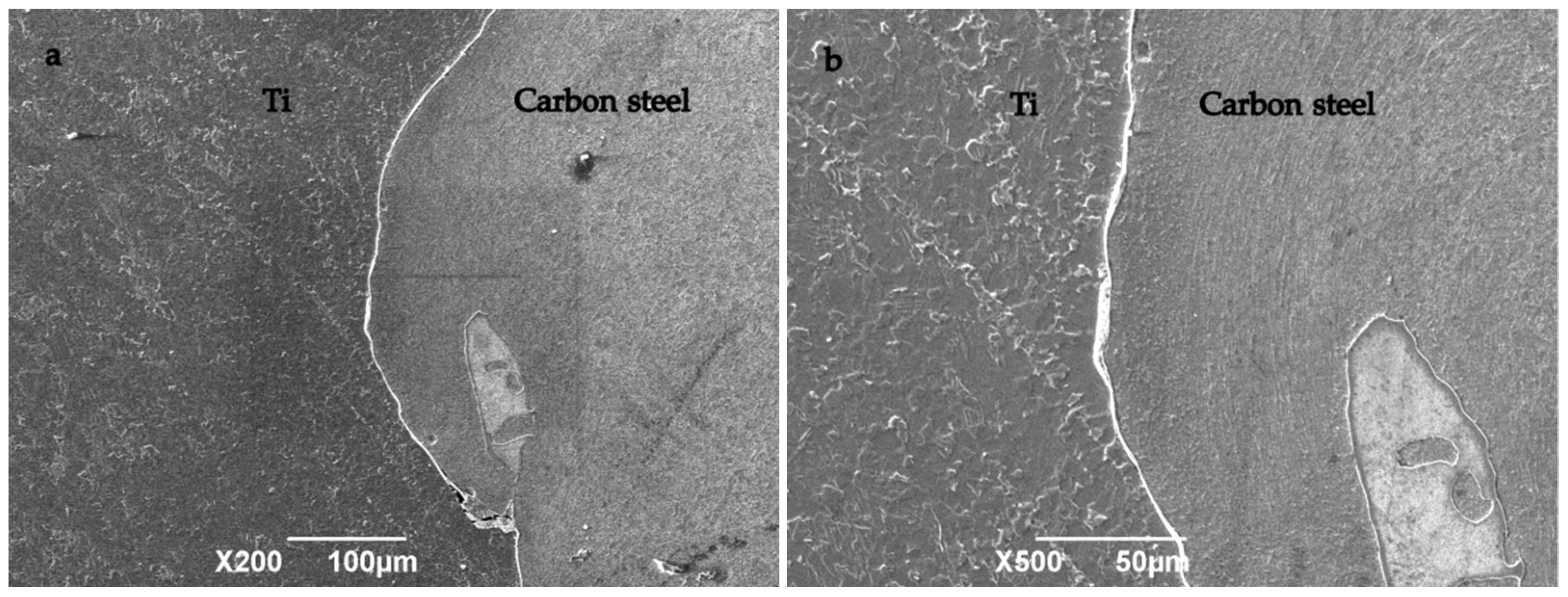
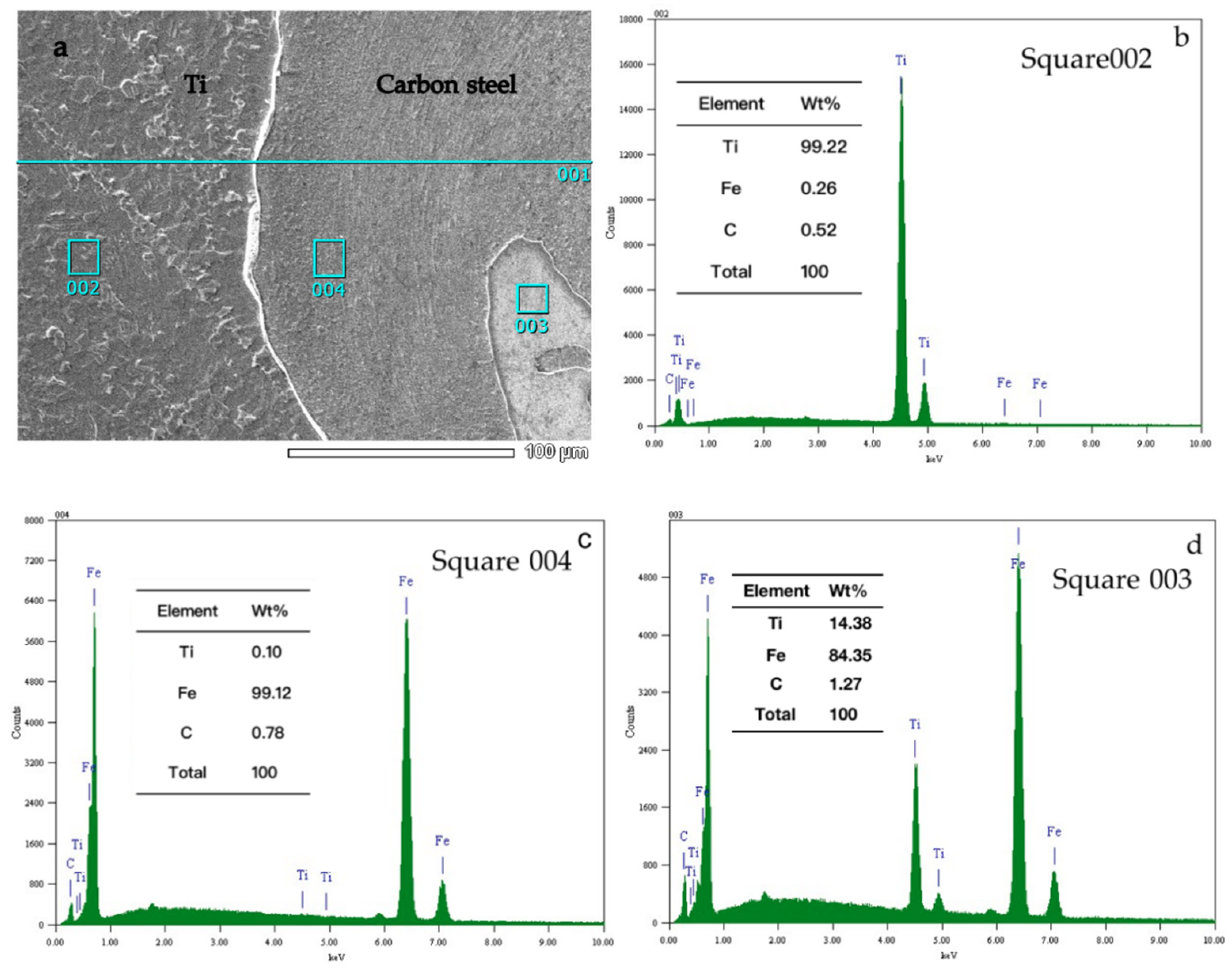
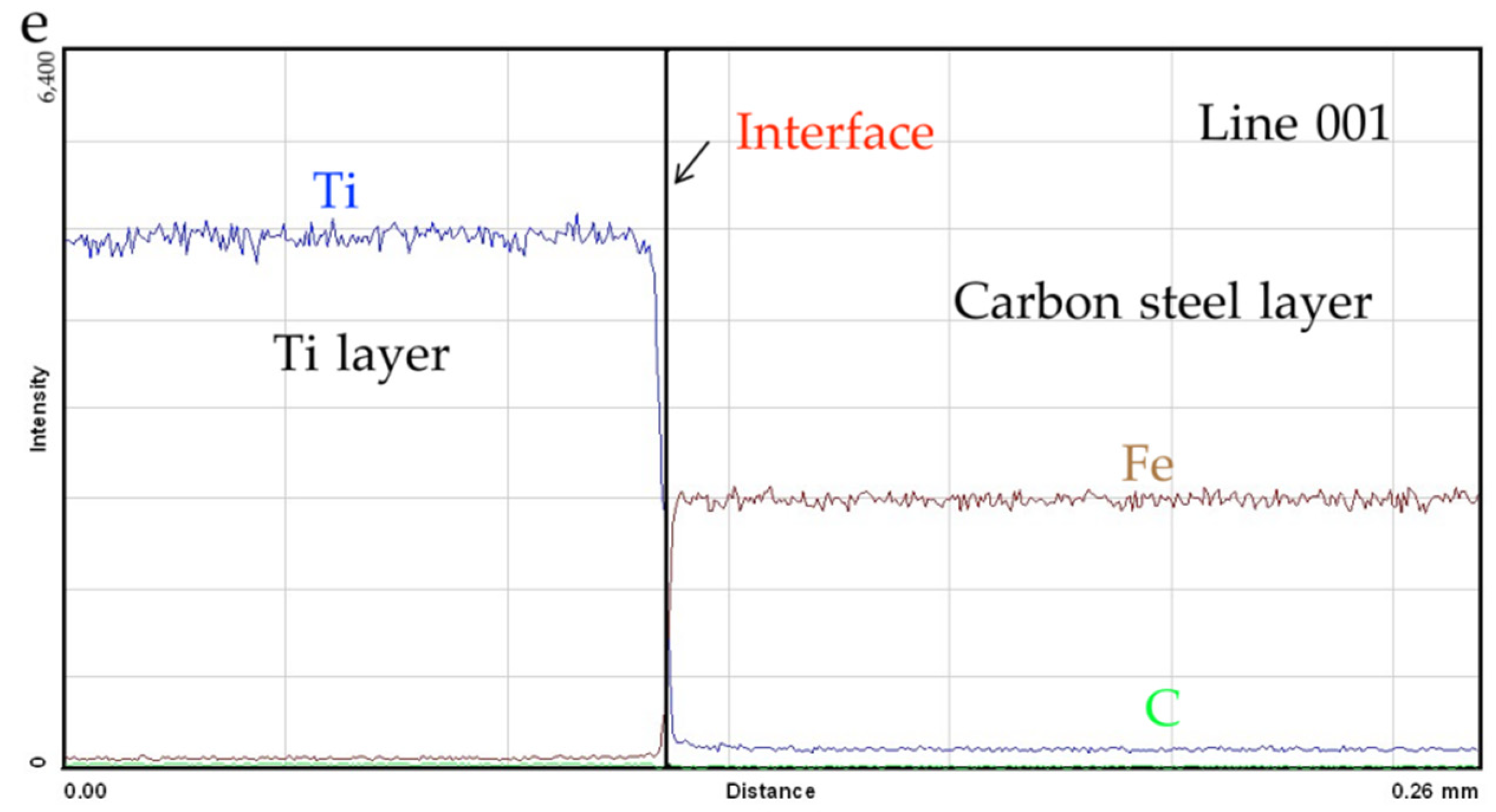
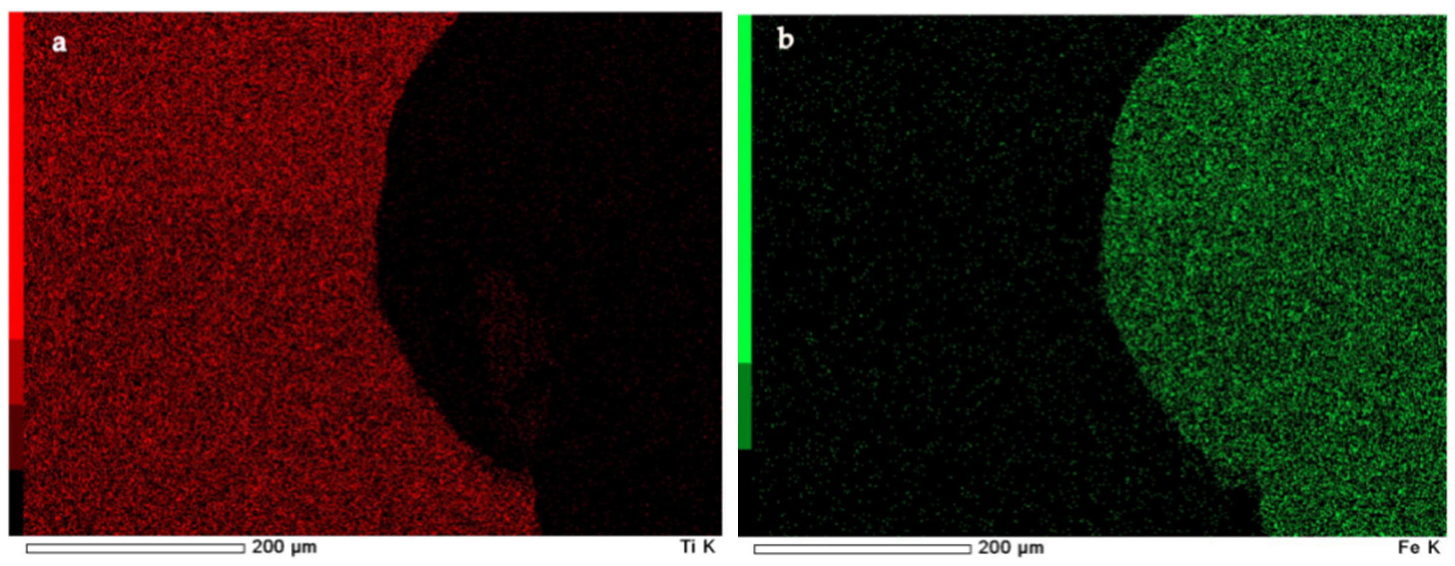
After explosive welding, the Ti and carbon steel were successfully joined together. The image using the ultrasonic C-scanning imaging technology shows the interface waves are uniform and there are no defects at the bounding interface. The optical and SEM observations show that the typical wavy interface has formed with no visible defects. No Fe or Ti element diffusion is found across the interface by EDS analyses.
(2)
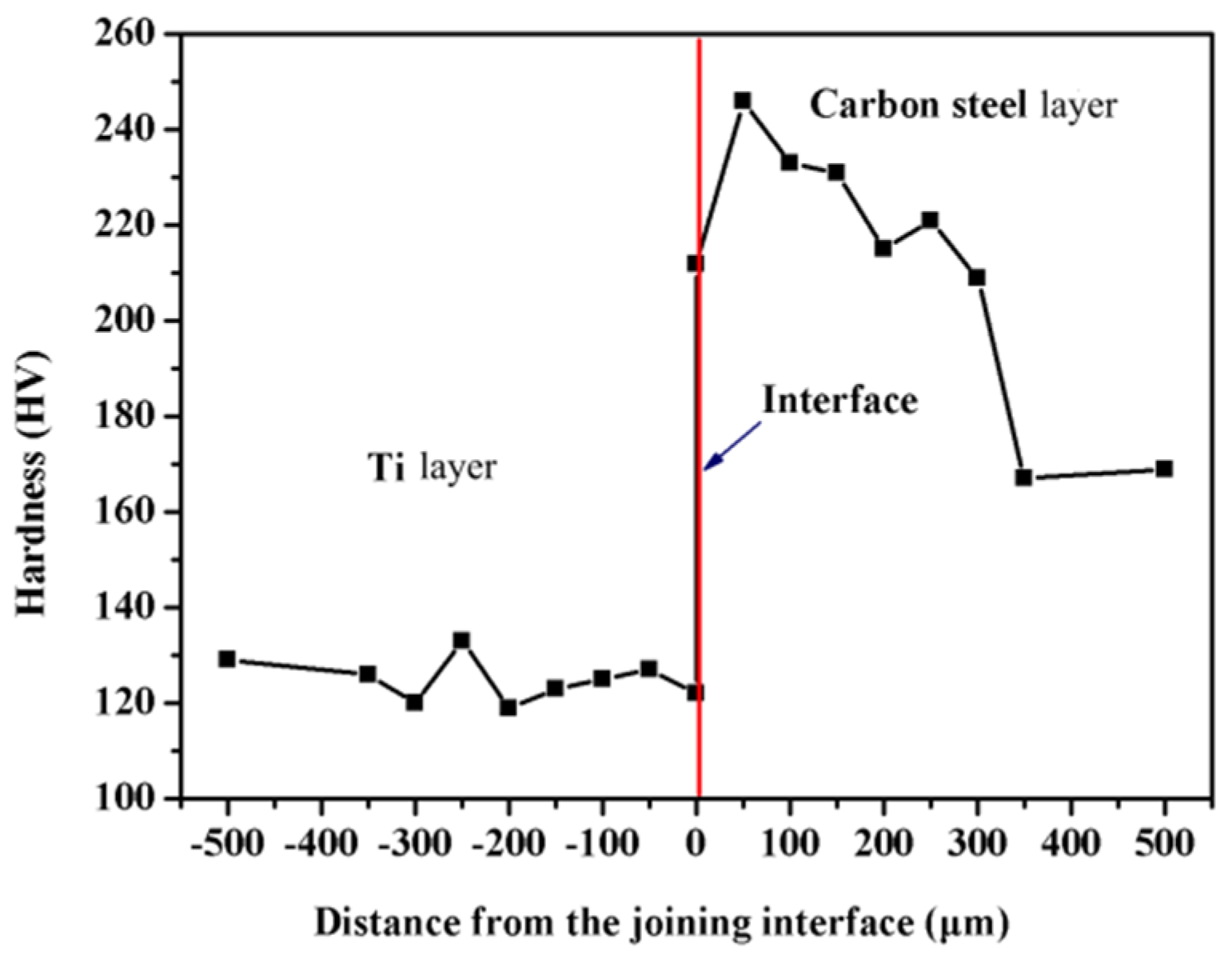
After heat treatment, the hardness values at the titanium layer of the clad plate are similar to that of the original Ti material, whereas the hardness values at the carbon steel layer increase from the bonding interface to 300 μm away.
(3)
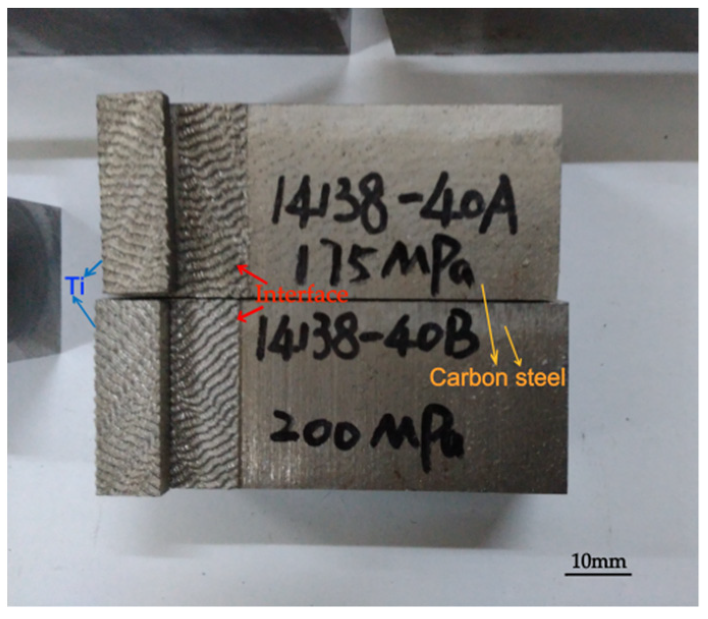
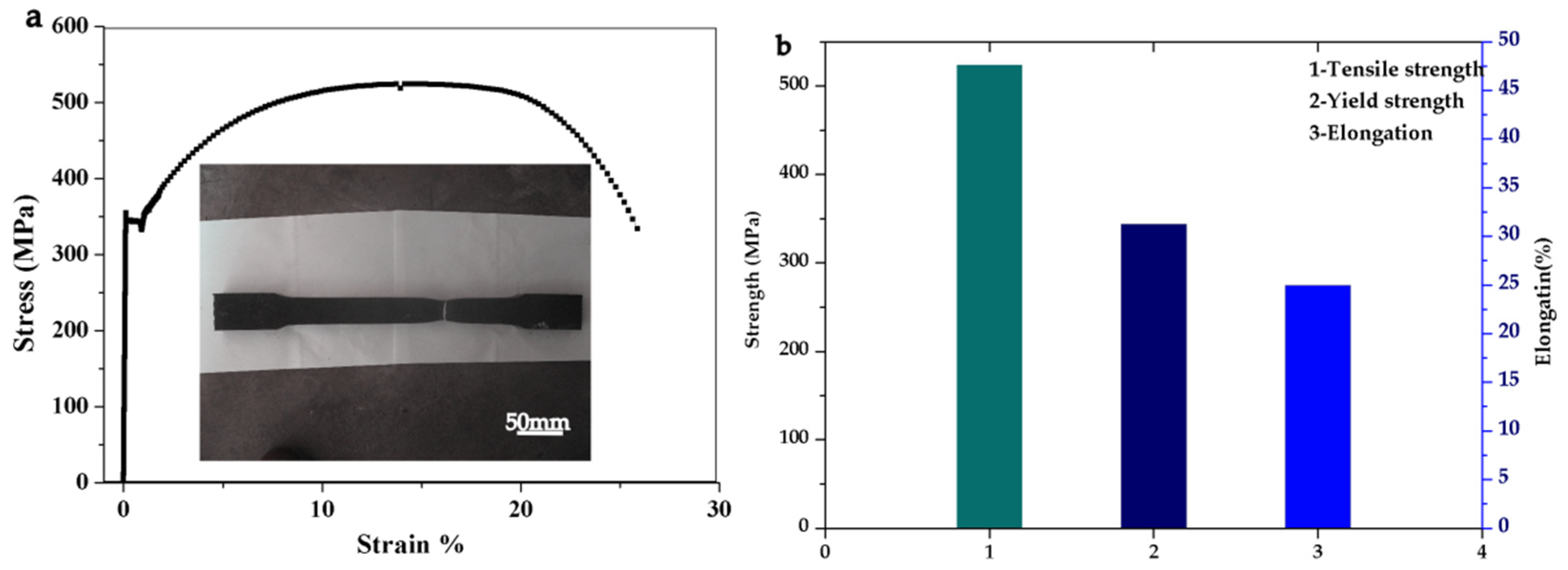
The results of shearing and tensile tests show that the mechanical properties of the clad plate meet the requirements of ASTM B898 standard.
(4)
Corrosion results show that the Ecorr absolute value of the clad plate increases about 20%, and the icorr value is 1 order of magnitude lower, compared with carbon steel material. It indicates that the corrosion resistance of the clad plate is better than carbon steel material. Compared with original Ti material, the corrosion resistance of titanium side in clad plate decreases.

Funding

Natural Science Basic Research Program of Shaanxi (Program No. 2021JM-403, 2021JQ-604); Xi’an Science and Technology Plan Project (Program No. 2020KJRC0100), Scientific Research Program Funded by Shaanxi Provincial Education Department (Program No. 21JC027); Xi’an Shiyou University College Students’ Innovation and Entrepreneurship Training Project (Program No. S202010705122, 202110705032).

Institutional Review Board Statement

Not applicable.

Informed Consent Statement

Not applicable.

Data Availability Statement

Some or all data, models, or code that support the findings of this study are available from the corresponding author upon reasonable request.

Acknowledgments

The author acknowledge the support of Funding.

Conflicts of Interest

The author declares there is no conflict of interest regarding the publication of this paper.

References

  1. MacDonald, D.E.; Markovic, B.; Allen, M.; Somasundaran, P.; Boskey, A.L. Surface analysis of human plasma fibronectin adsorbed to commercially pure titanium materials. J. Biomed. Mater. Res. 2015, 41, 120–130. [Google Scholar] [CrossRef]
  2. Li, X.D.; Qiu, C.Y.; Liu, Y.T.; Wang, H.F.; Zheng, D.D.; Zhu, Y.Y.; Zhang, S.Q. Effect of thermal deformation on microstructure and properties of TC18 titanium alloy produced by laser additive manufacturing. J. Iron Steel Res. Int. 2020, 27, 1476–1484. [Google Scholar] [CrossRef]
  3. Chen, Z.X.; Hu, H.X.; Guo, X.M.; Zheng, Y.G. Effect of groove depth on the slurry erosion of V-shaped grooved surfaces. Wear 2022, 488–489, 204133. [Google Scholar] [CrossRef]
  4. Zu, G.Y.; Sun, X.; Zhang, J.H. Interfacial Bonding Mechanism and Mechanical Performance of Ti/Steel Bimetallic Clad Sheet Produced by Explosive Welding and Annealing. Rare Metal Mater. Eng. 2017, 46, 906–911. [Google Scholar]
  5. Song, Q.N.; Tong, Y.; Li, H.L.; Zhang, H.N.; Xu, N.; Zhang, G.Y.; Bao, Y.F.; Liu, W.; Liu, Z.G.; Qiao, Y.X. Corrosion and cavitation erosion resistance enhancement of cast Ni-Al bronze by laser surface melting. J. Iron Steel Res. Int. 2021. [Google Scholar] [CrossRef]
  6. Zhang, L.M.; Li, Z.X.; Hu, J.X.; Ma, A.L.; Zhang, S.; Daniel, E.F.; Umoh, A.J.; Hu, H.X.; Zheng, Y.G. Understanding the roles of deformation-induced martensite of 304 stainless steel in different stages of cavitation erosion. Tribol. Int. 2021, 155, 106752. [Google Scholar] [CrossRef]
  7. Zhao, H. Characterization of the microstructure and bonding properties of zirconium-carbon steel clad materials by explosive welding. Scanning 2020, 2020, 8881898. [Google Scholar] [CrossRef]
  8. Li, S.Y.; Li, Q.S.; Chen, Z.G.; Wen, J.X. Microstructure and Mechanical Properties of Explosively Welded R60702/TA2 Composite Plate. Rare Metal Mater. Eng. 2019, 48, 1734–1741. [Google Scholar]
  9. Zhao, H.; Sheng, L.Y. Microstructure and mechanical properties of the Ag/316L composite plate fabricated by explosive welding. J. Manuf. Process. 2021, 64, 265–275. [Google Scholar] [CrossRef]
  10. Kaya, Y.; Eser, G. Production of ship steel-titanium bimetallic compositions through explosive welding. Weld World 2019, 63, 1547–1560. [Google Scholar] [CrossRef]
  11. Jiang, H.T.; Yan, X.Q.; Liu, J.X.; Duan, X.G. Effect of heat treatment on microstructure and mechanical property of Ti–steel explosive-rolling clad plate. Trans. Nonferrous Met. Soc. China 2014, 24, 697–704. [Google Scholar] [CrossRef]
  12. Akbari, S.A.A.; Sartangi, P.F. Effect of post-weld heat treatment on the interface microstructure of explosively welded titanium-stainless steel composite. Mater. Sci. Eng. A 2018, 119, 469–475. [Google Scholar] [CrossRef]
  13. Lazurenkoa, D.V.; Bataeva, I.A.; Malib, V.I. Structural Transformations Occurring upon Explosive Welding of Alloy Steel and High-Strength Titanium. Surf. Phase Transform. Diffus. 2018, 119, 469–476. [Google Scholar] [CrossRef]
  14. Wu, J.Q.; Wang, W.X.; Cao, X.Q.; Nan, Z. Interface Bonding Mechanism and Mechanical Behavior of AZ31B/TA2 Composite Plate Cladded by Explosive Welding. Rare Metal Mater. Eng. 2017, 46, 640–645. [Google Scholar]
  15. Zhao, H.; Zhu, L.; Li, P.C.; Zhang, J.Y.; Shen, C.Y.; Li, Y.; Hao, H.W.; Zhao, F.; Feng, H.L.; Gao, J.F. A Method for Dynamic Parameters of Metal Plate Explosive Welding. China Patent CN201610137182.6, 21 November 2017. [Google Scholar]
  16. Pouraliakbar, H.; Khalaj, G.; Jandaghi, M.R.; Fadaei, A.; Ghareh-Shiran, M.K.; Shim, S.H.; Hong, S.I. Three-layered SS321/AA1050/AA5083 explosive welds: Effect of PWHT on the interface evolution and its mechanical strength. Int. J. Press. Vessel. Pip. 2020, 188, 104216. [Google Scholar] [CrossRef]
  17. Shiran, M.R.; Bakhtiari, H.; Mousavi, S.A.; Khalaj, G.; Mirhashemi, S.M. Effect of Stand-Off Distance on the Mechanical and Metallurgical Properties of Explosively Bonded 321 Austenitic Stainless Steel-1230 Aluminum Alloy Tubes. Mater. Res. 2017, 20, 291–302. [Google Scholar] [CrossRef] [Green Version]
  18. ASTM Standards B898-09[S]; Standard Specification for Reactive and Refractory Metal Clad Plate. ASTM International: West Conshohocken, PA, USA, 2016.
  19. Khanzadeh, M.R.; Akbari Mousavi, S.A.; Amadeh, A.; Liaghat, G.H. Correlation between numerical finite element simulation and experiments for explosive cladding of nikel base super alloy on hot tool steel. Strain 2012, 48, 342–355. [Google Scholar] [CrossRef]
  20. Wilson Dhileep Kuma, C.; Saravanan, S.; Raghukandan, K. Influence of grooved base plate on microstructue and mechanical strength of aluminum-stainless steel explosive cladding. Metall. Mater. Eng. 2019, 72, 3269–3276. [Google Scholar]
  21. Zhang, H.; Jiao, K.X.; Zhang, J.L.; Liu, J. Microstructure and mechanical properties investigations of copper-steel composite fabricated by explosive welding. Mater. Sci. Eng. A 2018, 731, 278–287. [Google Scholar] [CrossRef]
  22. SVg, A.; Svk, A.; Sns, B. Microstructure and mechanical properties of sandwich copper/steel composites produced by explosive welding. Mater. Charact. 2019, 154, 294–303. [Google Scholar]
  23. Qiao, Y.; Wang, X.; Yang, L.; Wang, X.; Chen, J.; Wang, Z.; Zhou, H.; Zou, J.; Wang, F. Effect of aging treatment on microstructure and corrosion behavior of a Fe–18Cr–15Mn–0.66N stainless steel. J. Mater. Sci. Technol. 2022, 107, 197–206. [Google Scholar] [CrossRef]
Figure 1. A scheme of explosive welding: 1. detonator; 2. explosives; 3. Ti plate; 4. spacer; 5. carbon steel plate; and 6. anvil.
Metals 12 00129 g001
Figure 2. The clad plate after explosive welding: (a) appearance of the Ti-carbon steel clad plate; (b) the bonding interface image of the clad plate observed using the ultrasonic C-scanning; (c). the optical microstructure of the clad plate interface.
Metals 12 00129 g002
Figure 3. Interface microstructure of the clad plate (SEM): (a) low magnification; (b) high magnification.
Metals 12 00129 g003
Figure 4. Microstructure and corresponding EDS results: (a) interface microstructure; (b) spot analysis of square 002; (c) spot analysis of square 004; (d) spot analysis of square 003; and (e) Line (001) scan analysis across the bonding interface form Ti to carbon steel.
Metals 12 00129 g004aMetals 12 00129 g004b
Figure 5. Ti and Fe elements maps at low magnification (Figure 3a): (a) Ti element map; (b) Fe element map.
Metals 12 00129 g005
Figure 6. Hardness test results of the interface in the clad plate.
Metals 12 00129 g006
Figure 7. Specimens after shearing test.
Metals 12 00129 g007
Figure 8. Tensile test: (a) fractured tensile specimen and tensile curve of the clad plate; (b) tensile strength, yield strength and elongation values.
Metals 12 00129 g008
Figure 9. Polarization curves of the three specimens in 3.5% NaCl solution.
Metals 12 00129 g009
Table 1. The chemical composition of Ti and carbon steel materials (wt.%).
MaterialsChemical Element
TiCHNOFeTi
0.070.0100.020.170.01Bal.
Carbon steelCMnSiPSC
0.181.040.28≤0.003≤0.0030.18
Table 2. Values of parameters from polarization curves of original Ti material, carbon steel and clad plate (titanium side as working surface) in 3.5% NaCl solution.
MaterialsEcorr. (mV)icorr. (A/cm2)
Carbon steel−977.61.13 × 107
Original titanium material−746.78.79 × 109
Clad plate−782.42.11 × 108
Publisher’s Note: MDPI stays neutral with regard to jurisdictional claims in published maps and institutional affiliations.

