Article

Effect of Impact Block Shape and Material on Impact Wear Behavior of Zr-4 Alloy Cladding Tube

1
Tribology Research Institute, Key Lab of Advanced Technologies of Materials, Southwest Jiao Tong University, Chengdu 610031, China
2
China Institute of Atomic-Energy, Beijing 102413, China
3
School of Materials Science and Engineering, Southwest Jiaotong University, Chengdu 610031, China
*
Authors to whom correspondence should be addressed.
Metals 2022, 12(10), 1561; https://doi.org/10.3390/met12101561
Submission received: 1 September 2022 / Revised: 14 September 2022 / Accepted: 15 September 2022 / Published: 21 September 2022

Abstract

:
In a pressurized water reactor nuclear power plant, metal foreign matter in the rod–rod gap of the fuel assembly is constantly rubbed and collided with the fuel rod under continuous scouring of the coolant, resulting in wear to the fuel rod and even leakage of the perforation. In this work, the effects of different debris shapes and materials on the impact wear behavior of Zr−4 alloy tubes were studied through the dynamic response and damage of Zr−4 alloy tubes under cyclic impact. The results show that the sharper the shape of the impact block, the higher the wear rate of the Zr−4 alloy tube. Although the energy absorption rate of SA 508−A during the impact process is high, most of the energy is used for the wear of the impact block itself and the formation and peeling of the wear debris accumulation layer, and the damage to the Zr−4 alloy tube is small. The wear debris generated by the Zr−4 impact block is not easy to oxidize, and the wear caused by the cyclic impact is more serious. After the Zr−4 impact block cyclically impacts the Zr−4 alloy tube 200 w times, the Zr−4 alloy tube will be perforated due to wear. The oxidation and accumulation of wear debris and the wear mechanism in the impact process are mainly abrasive wear and surface peeling behavior. The occurrence of cutting and wear removal will promote the wear and thinning of the tube wall of the Zr−4 alloy tube, and the tube wall is easily perforated after thinning.

1. Introduction

Fuel cladding serves as the first and most important safety barrier in a pressurized water reactor (PWR) to contain uranium fuel and prevent fission products from spilling into the coolant [1]. This will not only cause huge economic losses, but also cause a major safety threat if the cladding is perforated due to severe wear [2]. The integrity of the fuel element cladding tube is of great significance to the operation and long−term development of nuclear power, and is receiving increasing attention.
Zr−4 alloy has a low thermal neutron absorption cross section, good corrosion resistance, and comprehensive mechanical properties in high−temperature water [3], and is a commonly used cladding material in pressurized water reactors. Grid−to−rod fretting wear (GTRF) induced by flow−induced vibration (FIV) is one of the main reasons for the damage of Zr−4 alloy cladding tubes [4], and its failure mechanism has attracted much attention. For decades, the effects of temperature [5,6], irradiation [7,8,9], load [10], amplitude [11], support conditions [12,13] and coolant flow rate [14] on GTRF have been comprehensively studied in various countries.
According to the IAEA’s report on the causes of fuel failures in water reactors, 40–45% of PWR fuel−rod breakage and leakage accidents are related to debris−induced fretting wear. A Korean data survey shows that debris−induced fretting wear is the second−largest cause of PWR fuel−rod failure, and the accident rate is only lower than GTRF [15,16]. The accident investigation of Qinshan 310 MWe unit in China shows that debris−induced fretting wear usually occurs in the early stage of fuel operating life, and with the increase of fuel consumption, the wear resistance of oxidized zirconium alloy tube increases [17,18]. Debris−induced fretting wear is another major cause of fuel−rod breakage and leakage, but its related research is rarely studied.
Debris−induced fretting wear refers to the fact that metal foreign matter in the reactor enters the rod–rod gap of the fuel assembly through the water hole of the lower tube seat driven by the coolant, and continuously rubs and collides with the fuel rod under the continuous scouring of the cooling water flow, resulting in fuel−rod wear and even perforation leaks [19]. It is known that in the primary circuit, in the process of assembling and pulling the rod from the fuel assembly, the Zr−4 alloy cladding tube is clamped by the grid spring/rigid protrusion, and its surface is inevitably scratched, and metal zirconium chips are generated at the same time [20]. In addition, SA508−3 low−alloy steel (SA508−3) [21] and austenitic 316L stainless steel (316L SS) [22] are widely used in the manufacture of primary circuit pressure vessels of nuclear power equipment: pressure vessels, steam generators, voltage stabilizers, main pump casings, etc. They all have good plasticity, toughness, corrosion resistance and ease of processing, and the materials have undergone strict inspections during the manufacturing process. However, due to the long−term exposure to harsh environments such as high temperature, high radiation, and pressure fluctuations [23], local hardening and high residual stress caused by manufacturing and surface finishing [24,25], wear and fatigue damage between components produce metal fragments. Although larger metal debris is blocked by the lower tube seat, smaller metal debris is stuck between the lower tube seat and the first layer of the grid, resulting in debris−induced fretting wear near the lower end plug of the fuel rod [18].
Chinese AFA3G fuel assemblies and French AREVA have better foreign−matter filtration ability after adopting an anti−foreign−body device in new assemblies [26,27]. Use of the anti−foreign−body device can effectively alleviate the debris−induced fretting wear, but there are still long and thin small−sized debris that can pass through the anti−foreign object device and cause wear to the fuel assembly. In addition, the wear of the Zr−4 alloy tube can be effectively reduced by applying a special coating [28], using a water−lubricated rod drawing process, and increasing the compression force of the inner spring of the fuel rod [20], but cannot prevent the occurrence of foreign−body abrasion. Therefore, it is necessary and valuable to carry out systematic failure mechanism research on the debris−induced fretting wear of cladding tubes.
The research focus of this experiment is to study the dynamic response and damage of Zr−4 alloy tube under cyclic impact under the scouring of coolant. The purpose is to investigate the impact wear of different debris shapes and materials on Zr−4 alloy tubes, which is of great significance for exploring the mechanism of debris−induced fretting wear impact wear in Zr−4 alloy tubes.

2. Materials and Methods

2.1. Materials

In this study, the Zircaloy−4 alloy cladding tube with a diameter of 10.0 mm and a thickness of 0.73 mm was cut to a 20 mm length by Wire Electrical Discharge Machining (WEDM). Three different shapes of impact blocks made of 316L stainless steel are shown in Figure 1: hemispherical, 120° obtuse cone and 60° acute cone.
Among the three materials used, the Vickers hardness of 316L SS is comparable to that of Zr−4, both of which are 198.3 HV. The Vickers hardness of SA508−3 is 193.8 HV, which is slightly lower than the other two materials. Chemical composition of the three material is shown in Table 1. The Fe element content of 316L SS is 66.77 %, the Fe element content of SA508−3 is 97.07%, and Zr−4 contains almost no Fe element. All test materials are supported by China Institute of Atomic Energy (CIAE). Before the test, the samples were ultrasonically cleaned with acetone solution and absolute ethanol and dried with hot compressed air.

2.2. Experimental Equipment Parameters

The schematic diagram of the self−developed impact wear testing machine used in this impact test is shown in Figure 2a. In the test, the voice coil motor (8) is controlled to perform reciprocating linear motion in the form of sine/cosine, and the tie rod (5) is driven to push the mass block (4) forward from the initial position. After the movement speed is continuously increased to the maximum value, the impact block (2) hits the tube sample (1) at this constant speed and bounces back to the initial position. The force sensor (3) and the displacement sensor (10) can record the changes to the contact force and displacement of the mass block (5) in real time during the impact process. The velocity response of the impact block (2) can be obtained by differentiating the displacement data. Knowing the change in velocity, the kinetic energy response in the impact process can be deduced using the kinetic energy theorem E = 1 2 m v 2 .
Figure 2b the schematic diagram of dynamic response of the impact process. Many research results show that the impact process can be divided into two stages: the Impact Stage and Rebound Stage [29,30,31]. During the impact stage, the impact block impacts the tube sample at the initial impact velocity of V1. With the continuous increase of the contact force, the impact velocity decreases, and the impact kinetic energy is transformed into elastic potential energy [32]. When the impact kinetic energy is completely transformed into elastic potential energy, the contact force reaches its peak value, and the impact velocity is 0 mm/s. As the stored elastic potential energy is released, the impact enters the Rebound Stage, the impact contact force decreases, and the impact velocity increases in the opposite direction. The energy dissipated (ΔE) from the contact to the separation of the impact block and the tube sample is mainly used for plastic deformation, friction and wear, crack initiation and propagation, oxidation, etc. [33].
Table 2 shows the experimental parameters of the impact wear test. The 800 g mass block (4) is controlled by the voice coil motor (8) to move at a constant speed of 100 mm/s, so that the impact blocks of different shapes and materials can impact the Zr−4 alloy tube 500,000 times with an initial impact energy of 4.0 mJ. During the impacting process, the solution of 1200 mg/L H3BO3 + 2.2 mg/L Li(OH) mixed with deionized water was used to simulate the primary circuit cooling water flushing the impacting contact surface at a flow rate of 10 mL/min [13]. Tadmor et al. [34,35] quantified the work of solid–liquid adhesion via implementing the Dupré’s gedanken experiment and establishing the concept of interfacial modulus, showing that solid–liquid adhesion under cooling liquid scour is one of the causes of energy loss during impact.
After the test, the dynamic response of the force, velocity and energy during the impact test was obtained by analyzing the data collected by the impact wear tester. The morphology and element compositions of wear scars on Zr−4 alloy tubes were characterized by optical microscope (Olympus OLS4000, Olympus Corporation, Tokyo, Japan), 3D morphology (Bruker Contour GT−K1, Selangor, Malaysia), scanning electron microscope ((SEM, JSM 7800F, JEOL, Tokyo, Japan), and X−ray spectroscopy (EDS, Aztec X-Max 80, Oxford Instrument, Abingdon, UK).

3. Results and Discussion

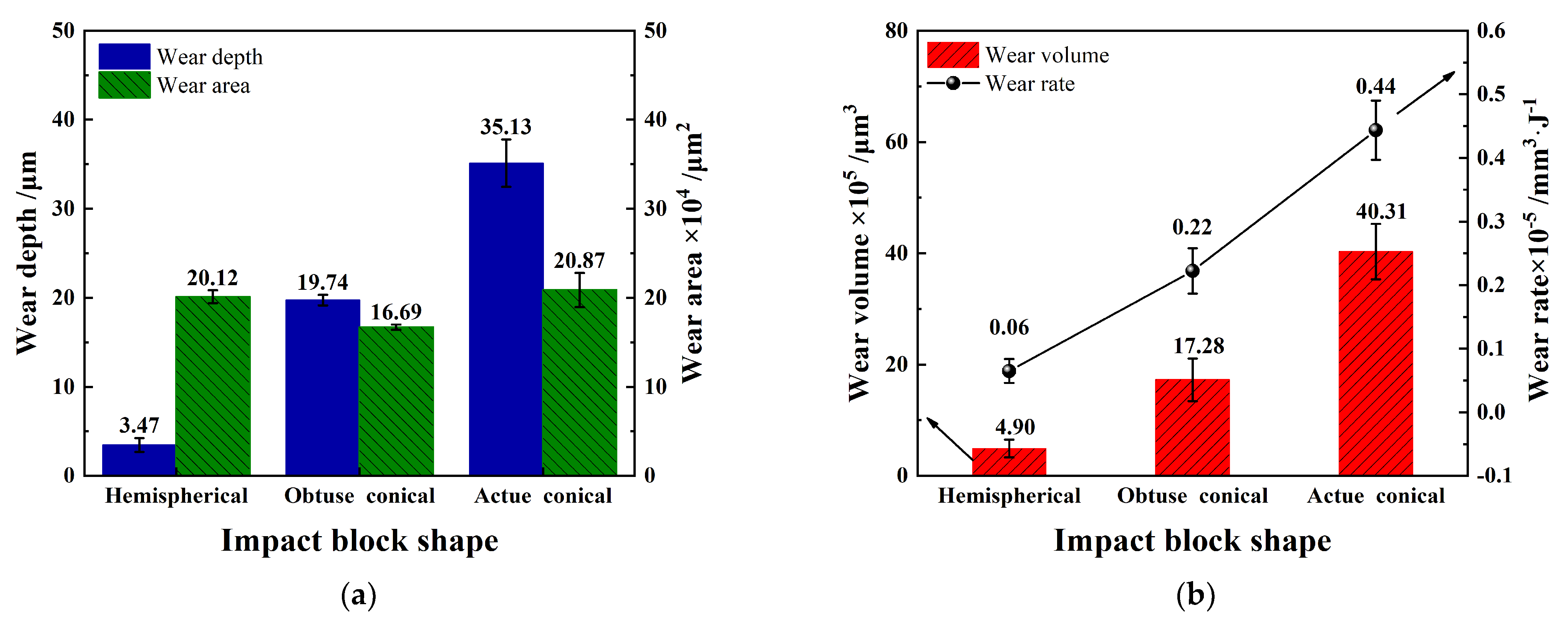
3.1. Influence of the Impact Block Shape

3.1.1. Dynamic Response

The impact wear behavior of 316LSS with different impact block shapes on Zr−4 alloy tube was studied. As shown in Figure 3a, under the same impact energy, the sharper the shape of the impact block, the more concentrated the impact stress, and the greater the peak force of the generated contact force. The hemispherical impact block has less contact force and longer contact time compared with the two conical impact blocks, as shown in Figure 3b.
Figure 4 shows the impact velocity and energy responses of different impact block shapes to Zr−4 alloy tubes. The difference velocity (ΔV) between the rebound velocity (V2) and the initial impact velocity (V1) corresponds to the result of energy dissipation (ΔE) calculated by the kinetic energy theorem Δ E = 1 2 m V 1 2 1 2 m V 2 2 . The hemispherical impact block has the smallest velocity change during the impact, while the acute conical impact block has the largest velocity change, indicating that the sharper the shape of the impact block, the more energy is lost during the impact. As shown in Figure 4c, the energy loss of the acute conical impact block is significantly higher than that of the hemispherical and the obtuse conical, and its energy absorption rate reaches 45.19%. Although the contact peak force and contact time of hemispherical and obtuse conical impact blocks are different during impact, the difference of energy loss is small. During the impact test, the absorption and action of energy is the most fundamental cause of all damage behaviors and is closely related to the final degree of wear [36].

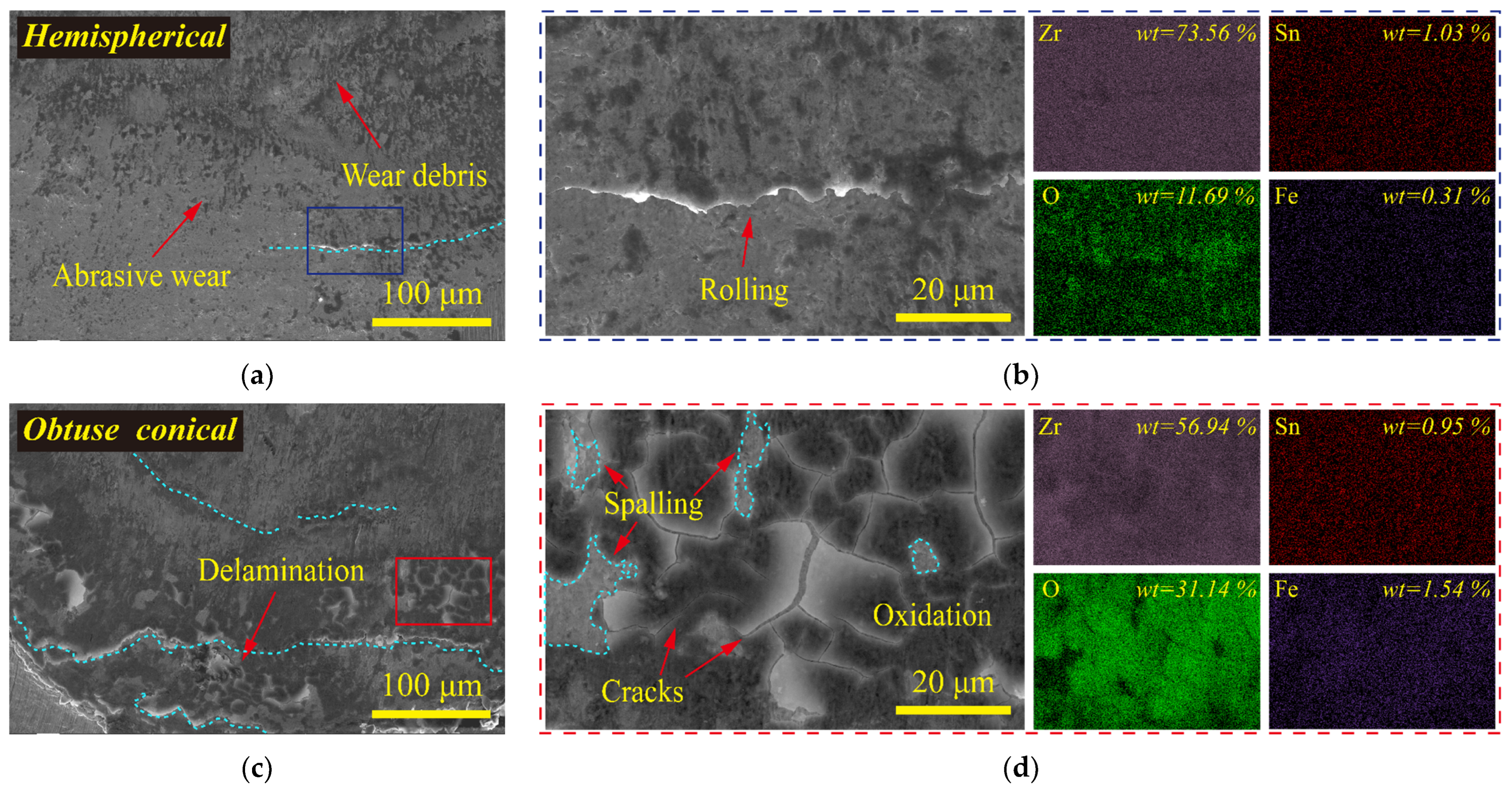
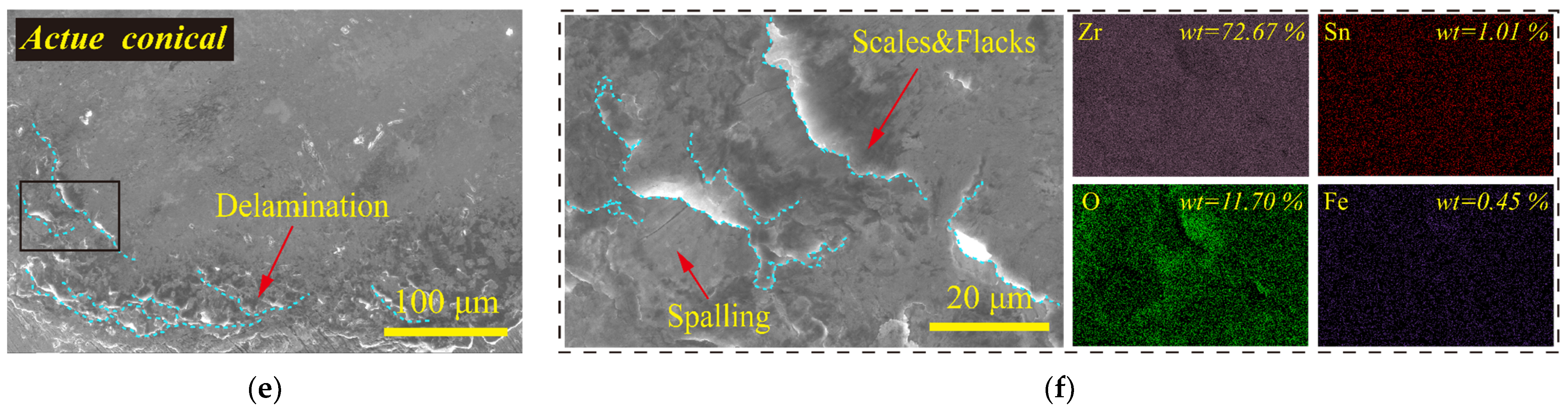
3.1.2. Wear Morphological Analysis

Figure 5 shows the 3D topography and sectional profiles of wear scars of Zr−4 alloy tube after 500,000 cycles of impact with varying shapes of impact blocks. The sharper the shape of the impact block, the more severe wear on the Zr−4 alloy tube. When the shape of the impact block is hemispherical, only a small amount of wear and removal occurs on the surface of the Zr−4 alloy tube. However, when the shape of the impact block is conical, the resulting wear scars have a concave center and a raised edge.
When the tube sample is worn, the droplet exhibits higher adhesion on the rough surface, which makes it more difficult for the droplet to detach from the surface [37]. As shown in Figure 5d, when the shape of the impact block is obtuse conical, the sectional profile of the wear scar is rough. A large amount of wear debris generated during the impact process is flattened and compacted at the bottom of the wear scar by the cyclic impact force, forming a wear debris accumulation layer [38]. The acute conical impact block causes severe wear at the bottom of the wear scar, and the accumulation of wear debris mainly occurs at the edge of the wear scar. Point contact can cause the contact stress to exceed the yield strength of the material, resulting in local plastic deformation [39]. After cyclic impact, the edges of the wear scars caused by the obtuse conical and acute conical impact blocks had plastic deformation, which caused damage to the uncontacted area of the Zr−4 alloy tube. However, when the impact block is hemispherical, there is no obvious plastic deformation on the edge of the wear scar of the Zr−4 alloy tube, and only abrasive wear occurs in the contact area.
Figure 6 shows that the shape of the impact block is hemispherical, the contact area with the Zr−4 alloy tube is large, which leads to the dispersion of stress. Although its wear depth is much lower than that of obtuse conical and acute conical impact blocks, its wear area is higher than that of obtuse conical impact blocks and is comparable to that of acute conical impact blocks. The wear volume of the Zr−4 alloy tube with the acute conical impact block is about 2 times that of the obtuse conical shape and 8 times that of the hemispherical shape. The volume of Zr−4 alloy tube worn by unit energy loss was taken as the wear rate of Zr−4 alloy tube by impact block. The sharper the shape of the impact block, the higher the wear rate of the Zr−4 alloy tube.
SEM was used to observe the microscopic morphology and element distribution of impact wear scars produced by varying impact block shapes. After 500,000 cycles of the hemispherical impact block impacting the Zr−4 alloy tube, only slight abrasive wear occurred on the surface of the Zr−4 alloy tube. The wear debris generated during the impact process is small, and most of the wear debris is swept away from the impact contact area by the water flow. A small amount of wear debris and oxides are scattered and covered on the surface of the wear scar, as shown in Figure 7a,b. The energy spectrum data showed that the dark part attached to the impact contact surface was oxide.
The obtuse conical and acute conical impact blocks have more concentrated stress when they impact, which cause more serious wear on the Zr−4 alloy, and more wear debris and oxides are generated during the cyclic impact process. As shown in Figure 7c,d, when the shape of the impact block is obtuse conical shape, the wear debris and oxides on the surface of the wear scar are layered in a large area. There are a large number of cracks and small pits on the surface of the accumulation layer, which are traces of peeling, adhesion and transfer of Zr−4 alloy tubes under the action of cyclic impact force [40].
Delamination with a stepped distribution appears on the edge of the wear scar when the impact block is acute conical (Figure 7e,f). More energy is used for the initiation and lateral expansion of micro−cracks, and the material is delaminated, resulting in a large amount of material removal at the bottom of the wear scar [12,41].
Although the wear degree of the Zr−4 alloy tube caused by the impact blocks of the same material and different shapes is different, they show the same wear mechanism. In addition, the Zr−4 alloy is not easily oxidized at room temperature, and the energy spectrum data shows that the content of O element is proportional to the content of Fe element and inversely proportional to the content of Zr element, showing that the oxides in the deposition layer mainly originate from 316L SS.

3.2. Influence of Impact Block Material

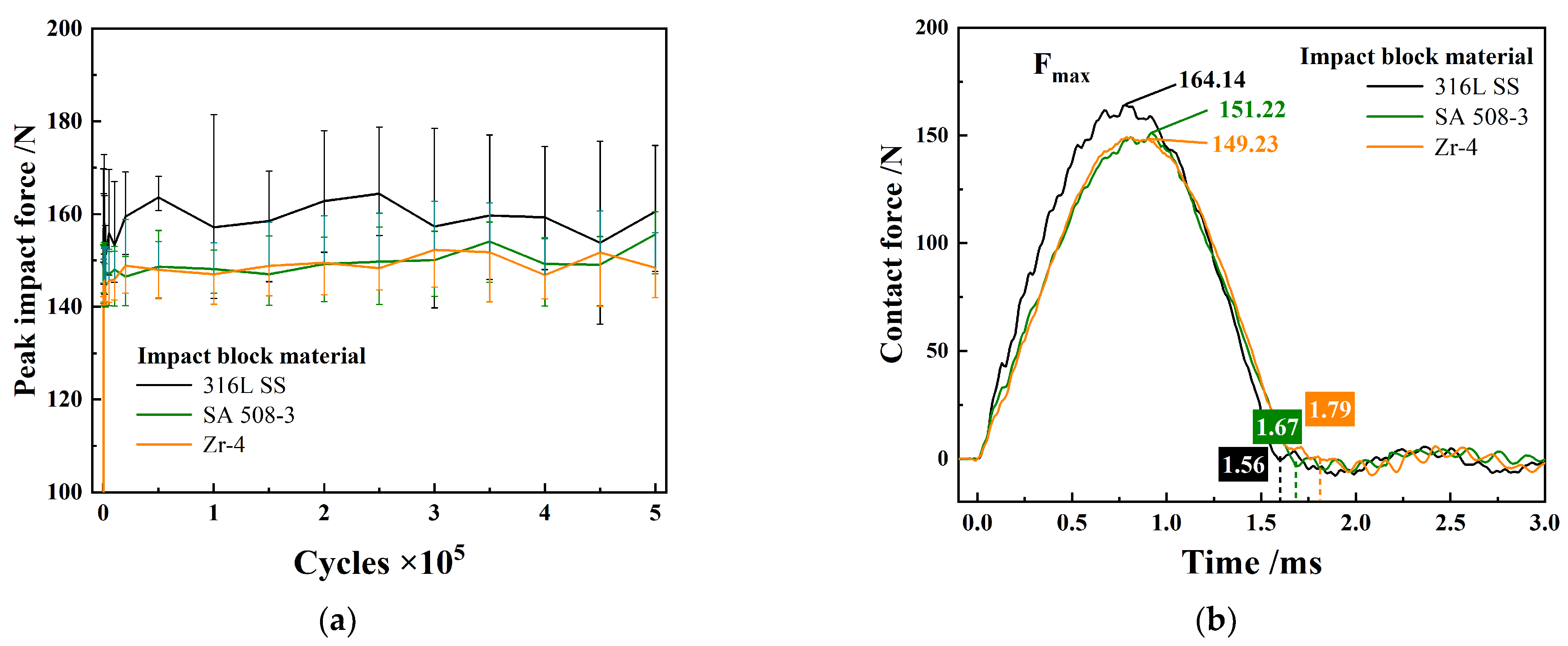
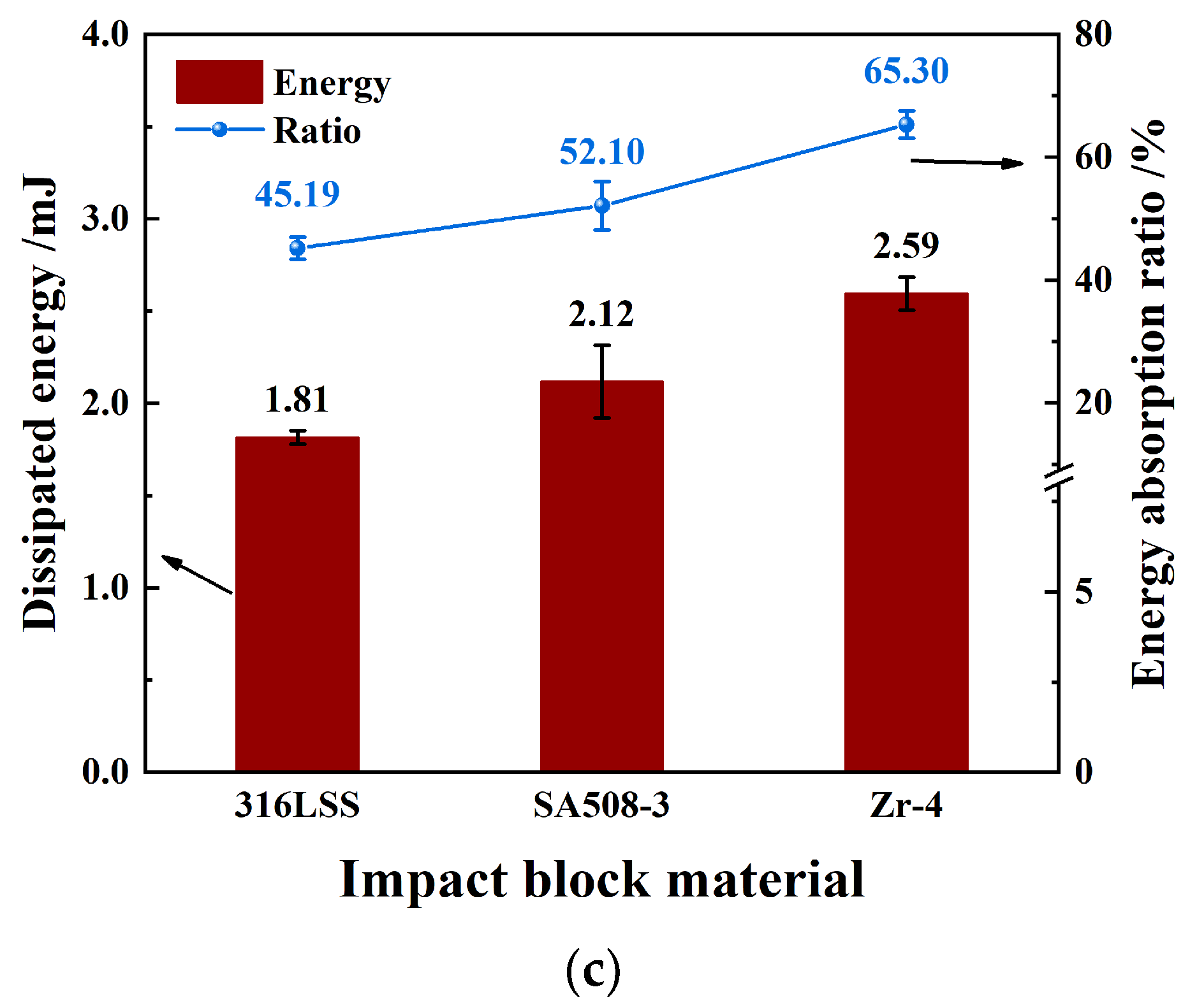
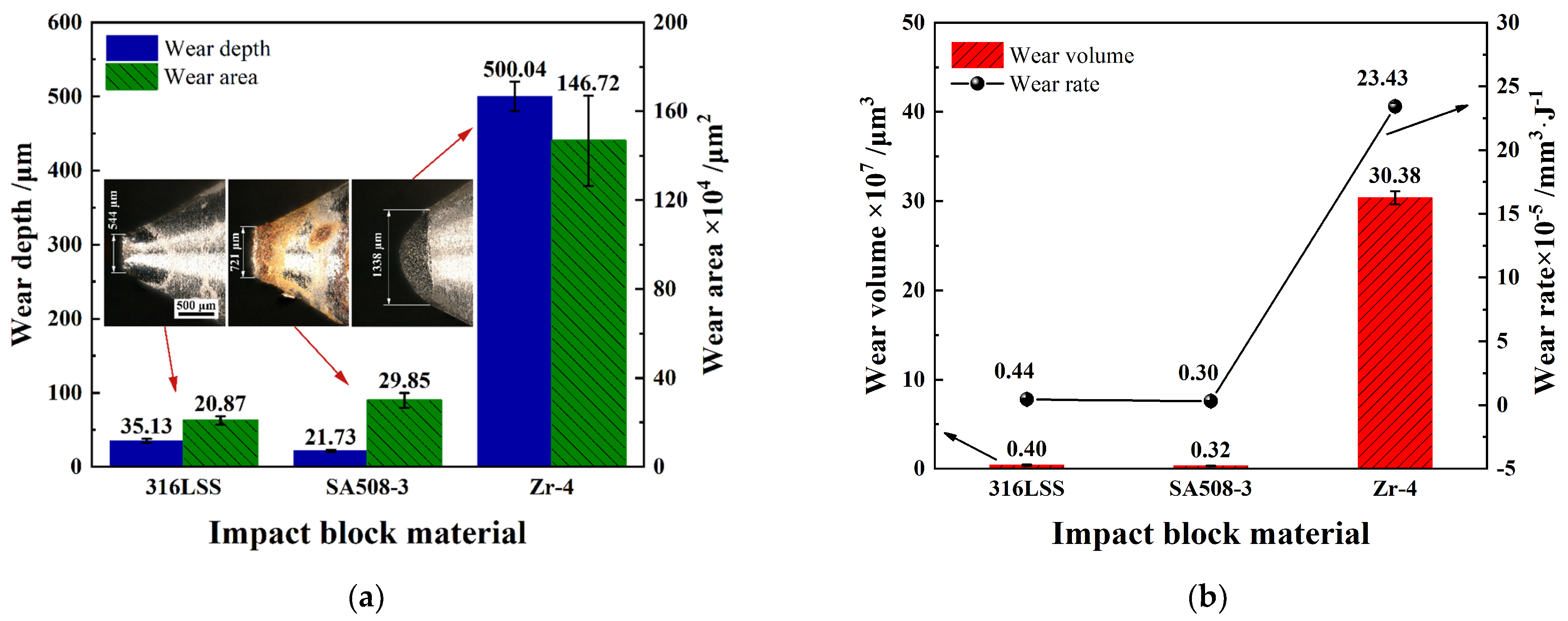
3.2.1. Dynamic Response

The exploration in the previous section shows that the wear of the Zr−4 alloy tube is more serious when the impact block is sharply conical. This section further explores the impact wear behavior of Zr−4 alloy tubes using three different materials of acute conical impact blocks. As shown in Figure 8a, with the increase of cycle impact times, the peak value of contact force fluctuates only slightly when the impact block material is SA 508−3 and Zr−4, while the impact block material is 316L SS, and the fluctuation is large, indicating that the impact contact surface of 316L SS impact block changes with different cycle impact times. In addition, the peak value of contact force of impact block material SA 508−3 and Zr−4 is lower than 316L SS.
Energy loss during impact stress loading is known to result in a reduction in stored elastic potential energy. Correspondingly, the peak value of the contact force when the impact kinetic energy is completely converted into elastic potential energy decreases. As shown in Figure 8b, compared with 316L SS, the contact force of SA 508−3 and Zr−4 impact blocks during the impact stress loading stage has a gentle upward trend, and the time to reach the peak of the contact force is later. The contact time between Zr−4 alloy tube and impact block of different materials is different during impact: the contact time between impact block of Zr−4 and Zr−4 alloy tube is the longest, reaching 1.79 ms; Followed by 1.67 ms of SA 508−3; The contact time of 316L SS was the shortest, only 1.56 ms.
Figure 9 shows the dynamic response of impact velocity and energy during impact. The energy loss of different impact block materials under the same impact energy is different. The impact block of Zr−4 loses the most energy in the impact process, and its energy absorption rate is as high as about 65.30%, followed by 52.10% of SA 508−3. The impact block of 316L SS has the lowest energy absorption rate, about 45.19%. The difference in dynamic response during the impact process means that the three material impact blocks will cause different degrees of wear to the Zr−4 alloy tube, and even the wear mechanism is different [36].

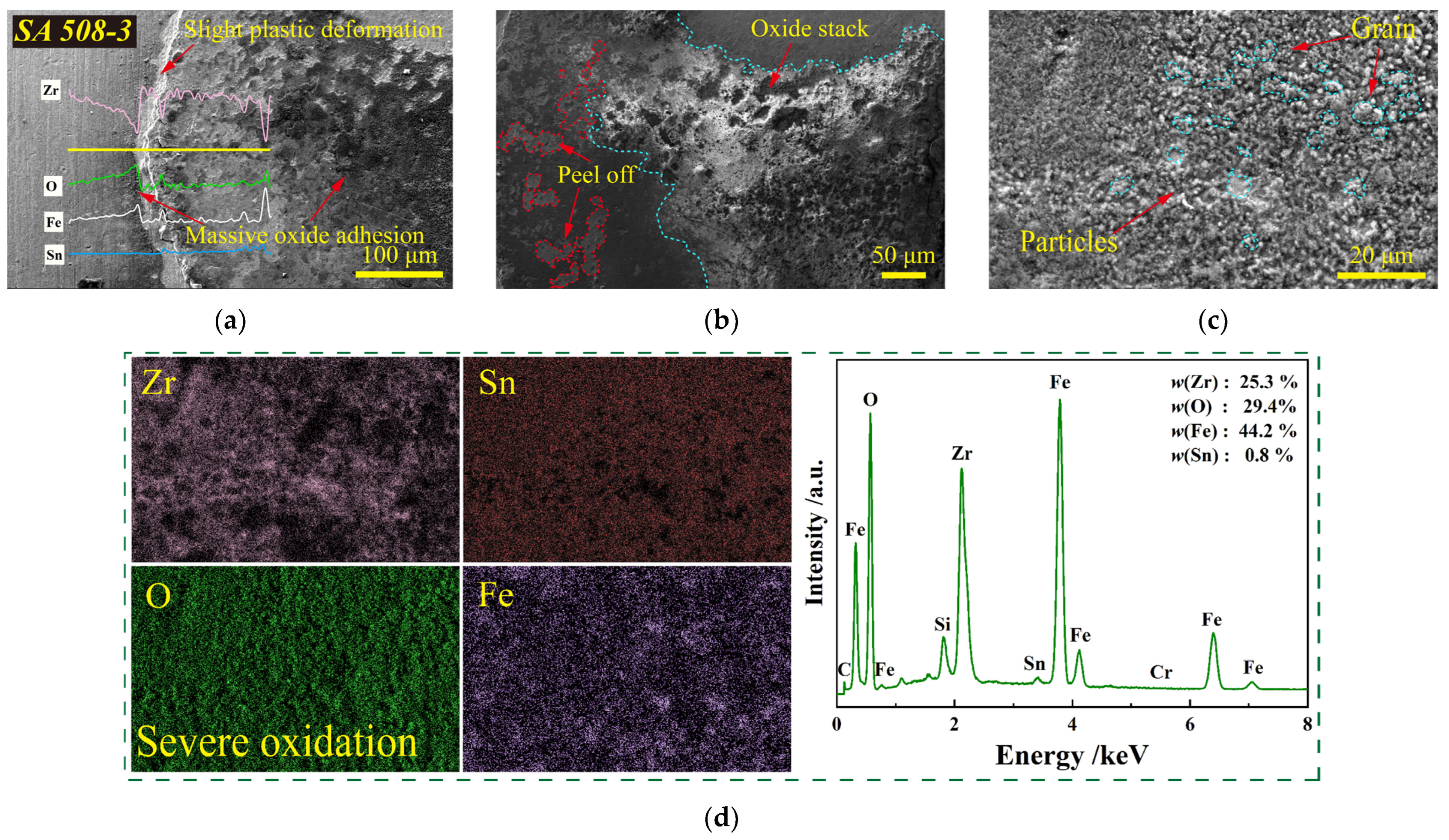
3.2.2. Wear Morphological Analysis

To further reveal the damage behavior and wear mechanism of Zr−4 alloy tubes with different impact block materials, the morphology of wear scars on Zr−4 alloy tubes was analyzed and discussed. Figure 10a,c the OM morphology of the wear scar shows that after 500,000 cycles of impact testing, using the impact block of 316L SS and SA 508−3, a large amount of oxides attached to the surface of the Zr−4 alloy tube. Moreover, the sectional profiles of the wear scar formed by the Zr−4 impact block on the Zr−4 alloy tube is smooth, and there is no bulge at the edge of the wear scar (Figure 10d). However, 316L SS and SA 508−3 impact blocks have bulges on the edges of the wear scars formed on the Zr−4 alloy tube. Among them, the bulge range caused by SA 508−3 impact block is larger than that of 316L SS, and the bulge height caused by 316L SS impact block is higher than that of SA 508−3. In addition, the profile of the wear scar formed by the SA 508−3 impact block on the Zr−4 alloy tube is rough. It can be seen from the above research that the roughness of the sectional profiles of the wear scar is due to peeling, adhesion and transfer of the wear debris accumulation layer during the impact process.
Figure 11 shows the wear statistics of Zr−4 alloy tubes after 500,000 impacts with impact blocks of different materials. The wear depth and wear area of the Zr−4 alloy tube caused by the impact block of Zr−4 is much higher than that of the impact block of 316L SS and SA 508−3. Although the wear depth of the Zr−4 alloy tube caused by the impact block of SA 508−3 is lower than that of the impact block of 316L SS, the wear area is larger. Since the hardness of SA 508−3 is lower than that of 316L SS and Zr−4, when the impact block impacts the Zr−4 alloy tube, the impact block of SA 508−3 worn more seriously than that of 316L SS (Figure 11a). Therefore, the impact contact area between the impact block of SA 508−3 and the Zr−4 alloy tube is larger, which caused a larger area of damage.
Figure 11b shows that the wear volume and wear rate caused by Zr−4 impact blocks are also much higher than those of 316L SS and SA 508−3 impact blocks, and the wear rate is as high as 23.43 mm3/J. The energy loss of SA 508−3 impact block during cyclic impact is higher than that of 316L SS, but its wear volume is lower, resulting in the wear rate of SA 508−3 impact block to Zr−4 alloy tube is only 0.30 mm3/J. The difference in wear rate shows that the loss of unit energy during the impact process causes different damage to the Zr−4 alloy tube, which again verifies that the impact block of different materials exhibited different wear mechanisms when impacting the Zr−4 alloy tube.
Next, we explored the wear mechanism of the Zr−4 alloy tubes by analyzing the microscopic morphology of the wear scars formed by the impact blocks of three different materials. Figure 12 is the scanning electron microscope and energy spectrum analysis of the wear scar morphology of the Zr−4 alloy tube after being cyclically impacted by a 316L SS impact block 500,000 times. The wear debris is flattened and compacted on the contact surface to form the wear debris accumulation layer, and a large area peels off (Figure 12a). There are wrinkles on the edge of the wear scar and a large number of peeling layers are distributed in a stepped manner, and plastic flow of the material occurs [42].
The data in Figure 12b shows that the wrinkle is mainly the plastic deformation of the Zr−4 alloy tube, while the peeling layers is the accumulation of wear debris. Wear debris accumulates in flakes, and delamination occurs and pits appear, exposing the base of the Zr−4 alloy tube (Figure 12c,d). The accumulation and spalling of wear debris at the bottom of the wear scar leads to a change in the contact surface during the impact process, resulting in the fluctuation of the contact force peak as shown in Figure 8a.
Figure 13 is the SEM morphology and EDS results of the wear scar of Zr−4 alloy tube after being cyclically impacted by a SA 508−3 impact block 500,000 times. Only slight plastic deformation occurred at the edges of the wear scar; oxides were abundantly attached to the bottom of the wear scar and to the uncontacted surfaces of the smooth Zr−4 alloy tube, but hardly to the plastically deformed area (Figure 13a). A large number of oxides are stacked on the bottom of the wear scar, and only a small amount of exfoliation at the edge of the wear scar (Figure 13b).
The enlarged morphology of the oxide in Figure 13c shows that the oxide is densely distributed on the surface of the wear scar in the form of particles. the granular oxides are abrasively worn and exfoliated in the form of particles, losing a lot of energy. [43]. Due to the extremely high Fe element content of SA508−3, the wear debris of the SA508−3 impact block can quickly react with O to form oxides to protect the Zr−4 alloy tube and play a role in reducing wear [38]. The energy spectrum data in Figure 13d shows that the surface of the wear scar is severely oxidized, and the oxide is densely accumulated.
To sum up, the impact block of SA 508−3 has high energy loss, but the damage to the Zr−4 alloy tube is small: (I) the hardness of SA 508−3 is lower, and the energy loss is used for the wear of the SA 508−3 impact block; (II) the oxides on the surface of the wear scars will be rapidly formed and aggregated after peeling off, and the energy loss is used to remove the wear debris accumulation layer.
Figure 14 is the SEM morphology and EDS results of the wear scar of Zr−4 alloy tube after being cyclically impacted by a Zr−4 impact block 500,000 times. There is no oxide layer accumulation at the bottom of the wear scar, and there is no obvious plastic deformation at the edge of the wear scar (Figure 14a). The impact block and the hard protrusions on the contact surface of the Zr−4 alloy tube rub against each other, and the “two−body wear” accelerates the wear and removal of the surface material [44] (Figure 14b). The furrows and the plastic deformation of the material caused by cutting will further promote the shedding of the material [45] (Figure 14c). The energy spectrum data of the wear debris in Figure 14d shows that the surface O element content is extremely low, which further confirms that the Zr−4 alloy is not easily oxidized under the action of cyclic impact at room temperature, and there is no oxide layer accumulation on the surface of the wear scar.

3.3. Impact Wear Mechanism

The above results show that the use of Zr−4 and acute conical impact blocks will cause the greatest damage to Zr−4 alloy tubes. By increasing the number of cyclic impacts to 2,000,000, the wear mechanism of Zr−4 alloy tubes is further analyzed. Figure 15 shows the wear of the impact block and the alloy tube after the Zr−4 and acute conical impact block impacted the Zr−4 alloy tube 2,000,000 times. The diameter of the wear scar on the Zr−4 alloy tube reached 1783 μm, and the edge of the wear scar was still smooth, but it is broken at the bottom of the wear scar (Figure 15a). The wall of the break edge is thinned and bent inward, showing ductile fracture, and forming cracks extending laterally.
The side edge of the impact block suffered a lot of wear due to cutting, resulting in the front end of the impact block still tapered after 2,000,000 impacts, and the impact stress was concentrated (Figure 15b). The 3D topography of the wear scar in Figure 15c shows that the wall of the Zr−4 alloy tube is thinned due to cutting and wear removal, and finally the thin−walled layer at the bottom of the wear scar is broken under the action of concentrated impact stress. In addition, the extension and expansion of the crack at the break will cause the flakes at the edge of the break to fall off, and the break at the bottom of the wear scar will become larger (Figure 15d).
Figure 16 shows the wear mechanism diagram of the Zr−4 alloy tube cyclically impacted with different impact block shapes and different impact block materials. The sharper the shape of the impact block, the more concentrated the impact stress, and the higher the wear rate, the more energy is lost for the expansion of plastic behavior. The plastic flow of the material at the edge of the wear scar causes the edge of the wear scar to bulge, causing damage to the area not contacted by the impact.
The wear mechanism of the impact block and Zr−4 alloy tube during the impact process is related to the material of the impact block: (1) 316L SS, SA 508−3 impact blocks produce wear debris that can form oxides at ambient temperatures. During the cyclic impact process, the oxide−acting third body is flattened and compacted on the surface of the wear scar by the impact force, and abrasive wear and surface peeling mainly occur [46,47]; (2) The wear debris generated by the Zr−4 impact block is not easily oxidized, and the cyclic impact process shows two−body wear, mainly cutting and wear removal, and the wear rate is extremely high.

4. Conclusions

After the cyclic impact test of Zr−4 alloy tube with impact blocks of different shapes (hemispherical, obtuse conical, acute conical) and different materials (316LSS, SA 508−3, Zr−4), the following conclusions were reached:
(a)
The effect of changing the shape of the impact block on the wear degree of the Zr−4 alloy tube is limited. However, the sharper the shape of the impact block, the more concentrated the stress during impact, and the more serious the damage to the Zr−4 alloy tube. The concentration of impact stress increases the wear range through plastic flow, and increases the wear depth through delamination.
(b)
Different impact block materials have different energy responses when impacted, and the impact wear mechanism is also different: (i) The wear debris generated by the impact blocks of 316LSS and SA 508−A will adhere to the surface of the alloy tube after oxidation. On the wear debris accumulation layer, the kinetic energy absorbed by impact is mainly used for abrasive wear and surface peeling behavior; (ii) Although the energy loss of SA 508−A during the impact process is large, most of it is used for the wear of the impact block and the formation and peeling of the wear debris accumulation layer, but the damage to the Zr−4 alloy tube is small; (iii) The wear debris generated by the impact block of Zr−4 is not easily oxidized, and it shows two−body wear during the cyclic impact process, mainly cutting and wear removal.
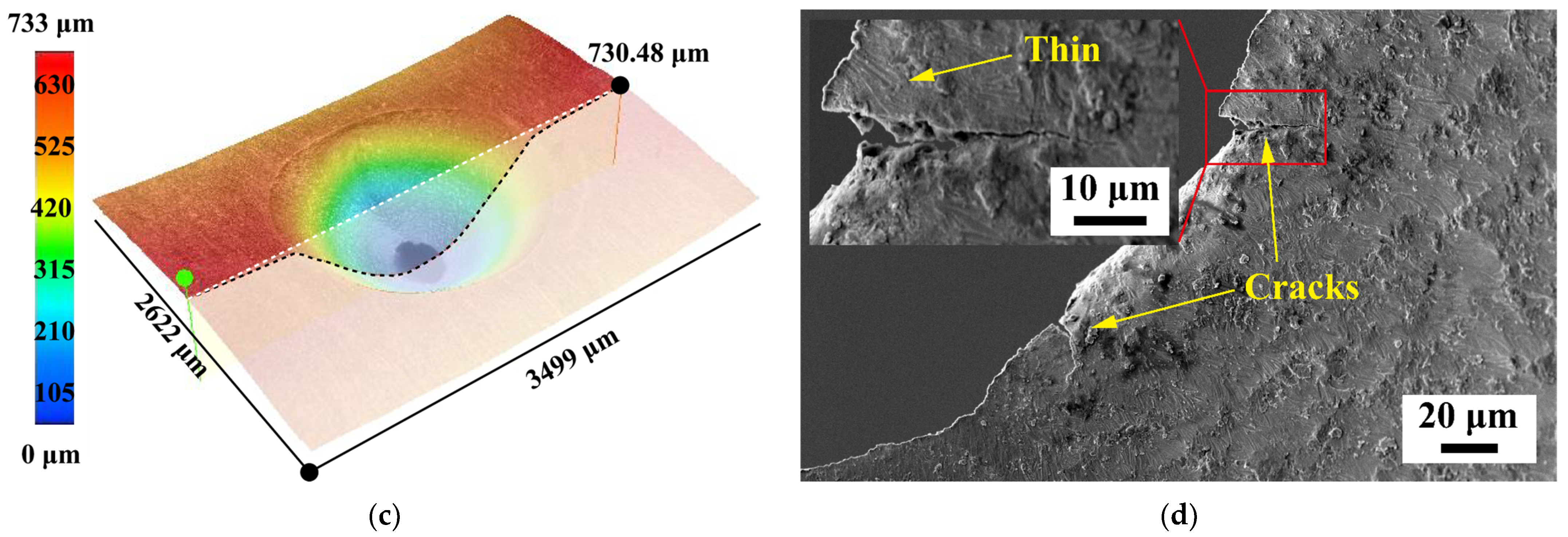
(c)
After the impact block of Zr−4 cyclically impacted the Zr−4 alloy tube 2,000,000 times, the Zr−4 alloy tube was perforated due to wear and tear, and the fracture showed ductile fracture.

Author Contributions

Writing—Original Draft and Formal analysis, S.Y.; Writing—Review and Editing, F.P, Y.H. and Z.C.; Investigation and resources, X.L.; Conceptualization and Methodology, D.L.; Data Curation, J.W. and L.H.; Project administration, Y.H. and Z.C. All authors have read and agreed to the published version of the manuscript.

Funding

This research was funded by National Science and Technology Major Project of China (2019ZX06004009) and Sichuan Science and Technology Planning Project (2022JDJQ0019).

Data Availability Statement

All data were presented in this manuscript.

Conflicts of Interest

The authors declare no conflict of interest.

References

  1. Yan, C.H.; Wang, R.S.; Wang, X.T.; Bai, G.H. Effects of ion irradiation on microstructure and properties of zirconium alloys—A review. Nucl. Eng. Technol. 2015, 47, 323–331. [Google Scholar] [CrossRef]
  2. Cai, Z.B.; Li, Z.Y.; Yin, M.G.; Zhu, M.H.; Zhou, Z.R. A review of fretting study on nuclear power equipment. Tribol. Int. 2020, 144, 106095. [Google Scholar] [CrossRef]
  3. Duan, Z.G.; Yang, H.L.; Satoh, Y.; Murakami, K.; Kano, S.; Zhao, Z.S.; Shen, J.J.; Abe, H. Current status of materials development of nuclear fuel cladding tubes for light water reactors. Nucl. Eng. Des. 2017, 316, 131–150. [Google Scholar] [CrossRef]
  4. Lu, R.Y.; Karoutas, Z.; Sham, T.L. CASL Virtual reactor predictive simulation: Grid−to−rod fretting wear. Met. Mater. Soc. 2011, 63, 3–58. [Google Scholar] [CrossRef]
  5. Blau, P.J.; Qu, J.; Lu, R. Modeling of complex wear behavior associated with grid−to−rod fretting in light water nuclear reactors. JOM 2016, 68, 2938–2943. [Google Scholar] [CrossRef]
  6. Lu, W.; Thouless, M.D.; Hu, Z.; Wang, H.; Ghelichi, R.; Wu, C.H.; Kamrin, K.; Parks, D. CASL Structural mechanics modeling of Grid−to−Rod Fretting (GTRF). JOM 2016, 68, 2922–2929. [Google Scholar] [CrossRef]
  7. Jiang, H.X.; Duan, Z.W.; Zhang, B.B.; Zhao, X.Y.; Wang, P. Influence of ions irradiation on the microstructural evolution, mechanical and tribological properties of Zr−4 alloy. Appl. Surf. Sci. 2019, 498, 143821. [Google Scholar] [CrossRef]
  8. Jang, H.X.; Duan, Z.W.; Zhang, B.B.; Zhao, X.Y.; Wang, P. Wear behavior of zirconium−4 alloy after different irradiation damage level. Appl. Surf. Sci. 2020, 509, 145373. [Google Scholar] [CrossRef]
  9. Jiang, H.X.; Duan, Z.W.; Zhang, B.B.; Zhao, X.Y.; Wang, P. Fretting wear behaviors of Zr−4 alloy under different ions irradiation conditions. Tribol. Int. 2020, 152, 106553. [Google Scholar] [CrossRef]
  10. Wang, H.; Hu, Z.P.; Lu, W.; Thouless, M.D. The effect of coupled wear and creep during grid−to−rod fretting. Nucl. Eng. Des. 2017, 318, 163–173. [Google Scholar] [CrossRef] [Green Version]
  11. Lee, Y.H.; Kim, H.K.; Jung, Y.H. Effect of impact frequency on the wear behavior of spring−supported tubes in room and high temperature distilled water. Wear 2005, 259, 329–339. [Google Scholar] [CrossRef]
  12. Kim, K.T. The effect of fuel rod supporting conditions on fuel rod vibration characteristics and grid−to−rod fretting wear. Nucl. Eng. Des. 2010, 240, 1386–1391. [Google Scholar] [CrossRef]
  13. Lee, Y.H.; Kim, H.K. Fretting wear behavior of a nuclear fuel rod under a simulated primary coolant condition. Wear 2013, 301, 569–574. [Google Scholar] [CrossRef]
  14. Kim, K.T. The study on grid−to−rod fretting wear models for PWR fuel. Nucl. Eng. Des. 2009, 239, 2820–2824. [Google Scholar] [CrossRef]
  15. Kim, K.T. Evolutionary developments of advanced PWR nuclear fuels and cladding materials. Nucl. Eng. Des. 2013, 263, 59–69. [Google Scholar] [CrossRef]
  16. Kim, K.T. Self−sufficient nuclear fuel technology development and applications. Nucl. Eng. Des. 2012, 249, 287–296. [Google Scholar] [CrossRef]
  17. Qu, J.; Cooley, K.M.; Shaw, A.H.; Lu, R.Y.; Blau, P.J. Assessment of wear coefficients of nuclear zirconium claddings without and with pre−oxidation. Wear 2016, 356–357, 17–22. [Google Scholar] [CrossRef]
  18. Xue, X.C. Fuel Failure Analysis and Supervise. Nucl. Power Eng. Technol. 2011, 1, 25–41. [Google Scholar]
  19. Li, D.X. Effect of normal force on Fretting Wear of zirconium alloy cladding tubes in simulated PWR primary loop environment. China Sci. Technol. Inf. 2021, 18, 105–107. [Google Scholar]
  20. Chen, T.Y. Study on water lubricated drawing rod technology for AFA 3G fuel assembly. Prog. Rep. China Nucl. Sci. Technol. 2019, 6, 138–143. [Google Scholar]
  21. Seifert, H.P.; Ritter, S. Stress corrosion cracking of low−alloy reactor pressure vessel steels under boiling water reactor conditions. J. Nucl. Mater. 2008, 372, 114–131. [Google Scholar] [CrossRef]
  22. Han, G.; Lu, Z.; Ru, X.; Chen, J.; Xiao, Q.; Tian, Y.W. Improving the oxidation resistance of 316L stainless steel in simulated pressurized water reactor primary water by electropolishing treatment. J. Nucl. Mater. 2015, 467, 194–204. [Google Scholar] [CrossRef]
  23. Chen, J.J.; Xiao, Q.; Lu, Z.P.; Ru, X.K.; Peng, H.; Xiong, Q.; Li, H.J. Characterization of interfacial reactions and oxide films on 316L stainless steel in various simulated PWR primary water environments. J. Nucl. Mater. 2017, 489, 137–149. [Google Scholar] [CrossRef]
  24. Huang, Y.; Wu, W.S.; Cong, S.; Ran, G.; Cen, D.X.; Li, N. Stress corrosion behaviors of 316LN stainless steel in a simulated PWR primary water environment. Materials 2018, 11, 1509–1522. [Google Scholar] [CrossRef] [PubMed]
  25. Liu, T.G.; Xia, S.; Bai, Q.; Zhou, B.X.; Lu, Y.H.; Shoji, T.S. Evaluation of grain boundary network and improvement of intergranular cracking resistance in 316L stainless steel after grain boundary engineering. Materials 2019, 12, 242–259. [Google Scholar] [CrossRef] [PubMed]
  26. Kopeć, M.; Malá, M.; Cvrček, L.; Krejčí, J. Debris−fretting test of coated and uncoated Zr−1% Nb Cladding. Acta Polytech. CTU Proc. 2019, 24, 556. [Google Scholar] [CrossRef]
  27. Ru, J.; Xiao, Z.; Zhu, F.W.; Zhang, L.; Qin, M.; Liu, Y.H. Analysis of measures for safe operation of PWR fuel assemblies. Nucl. Power Eng. 2017, 38, 175–179. [Google Scholar]
  28. Kopeć, M.; Pata, O.; Malá, M.; Halodová, P.; Cvrček, L.; Krejčí, J. On debris−fretting impact—The study of oxide and chromium layer application. J. Nucl. Eng. Radiat. Sci. 2020, 7, 18021–18026. [Google Scholar]
  29. Alves, J.; Peixinho, N.; Silva, M.T.D.; Flores, P.; Lankarani, H.M. A comparative study of the viscoelastic constitutive models for frictionless contact interfaces in solids. Mech. Mach. Theory 2015, 85, 172–188. [Google Scholar] [CrossRef]
  30. Machado, M.; Moreira, P.; Flores, P.; Lankarani, H.M. Compliant contact force models in multibody dynamics: Evolution of the Hertz contact theory. Mech. Mach. Theory 2012, 53, 99–121. [Google Scholar] [CrossRef]
  31. Pereira, C.M.; Ambrósio, J.A. A critical overview of internal and external cylinder contact force models. Nonlinear Dyn. 2011, 63, 681–697. [Google Scholar] [CrossRef]
  32. Gilardi, G.; Sharf, I. Literature survey of contact dynamics modelling. Mech. Mach. Theory 2002, 37, 1213–1239. [Google Scholar] [CrossRef]
  33. Luo, Y.; Ning, C.M.; Dong, Y.Y.; Xiao, C.; Wang, X.T.; Peng, H.; Cai, Z.B. Impact abrasive wear resistance of CrN and CrAlN coatings. Coatings 2022, 12, 427. [Google Scholar] [CrossRef]
  34. Tadmor, R. Open problems in wetting phenomena: Pinning retention forces. Langmuir 2022, 37, 6357–6372. [Google Scholar] [CrossRef] [PubMed]
  35. Tang, S.; Yao, C.W.; Tadmor, R.; Sebastian, D. Lateral retention of water droplets on solid surfaces without gravitational effect. MRS Commun. 2020, 10, 449–454. [Google Scholar] [CrossRef]
  36. Lin, Y.W.; Cai, Z.B.; Chen, Z.Q.; Qian, H.; Tang, L.C.; Xie, Y.C.; Zhu, M.H. Influence of diameter–thickness ratio on alloy Zr−4 tube under low−energy impact fretting wear. Mater. Today Commun. 2016, 8, 79–90. [Google Scholar] [CrossRef]
  37. Jena, A.K.; Bhimavarapu, Y.V.R.; Tang, S.; Liu, J.; Das, R.; Gulec, S.; Vinod, A.; Yao, C.W.; Cai, T.X.; Tadmor, R. Stages that lead to drop depinning and onset of motion. Langmuir ACS J. Surf. Colloids 2022, 38, 92–99. [Google Scholar]
  38. Blau, P.J. A multi−stage wear model for grid−to−rod fretting of nuclear fuel rods. Wear 2014, 313, 89–96. [Google Scholar] [CrossRef]
  39. Blades, L.; Hills, D.; Nowell, D.; Evans, K.E.; Smith, C. An exploration of debris types and their influence on wear rates in fretting. Wear 2020, 450, 203–252. [Google Scholar] [CrossRef]
  40. Priya, R.; Mallika, C.; Mudali, U.K. Wear and tribocorrosion behaviour of 304L SS, Zr−702, Zircaloy−4 and Ti−grade2. Wear 2014, 310, 90–100. [Google Scholar] [CrossRef]
  41. Bhatti, N.A.; Wahab, M.A. Fretting fatigue crack nucleation: A review. Tribol. Int. 2018, 121, 121–138. [Google Scholar] [CrossRef]
  42. Ren, Y.P.; Wang, P.F.; Cai, Z.B.; He, J.F.; Lu, J.S.; Peng, J.F.; Xu, X.J.; Zhu, M.H. Dynamic response characteristics and damage mechanism of impact wear for deep plasma nitrided layer. Tribol. Int. 2022, 170, 107496. [Google Scholar] [CrossRef]
  43. Iwabuchi, A. The role of oxide particles in the fretting wear of mild steel. Wear 1991, 151, 301–311. [Google Scholar] [CrossRef]
  44. Kim, J.S.; Park, S.M.; Lee, Y.Z. The effects of wear debris under fluid flow environment on fretting wear mechanism of nuclear fuel cladding tube supported by supporting grid. Tribol. Trans. 2010, 53, 452–462. [Google Scholar] [CrossRef]
  45. Silva, C.S.; Henriques, B.; de Oliveira, A.P.N.; Silva, F.; Gomes, J.R.; Souza, J.C. Micro−scale abrasion and sliding wear of zirconium−lithium silicate glass−ceramic and polymer−infiltrated ceramic network used in dentistry. Wear 2020, 448, 203214. [Google Scholar] [CrossRef]
  46. Zhang, L.F.; Lai, P.; Liu, Q.D.; Zeng, Q.F.; Lu, J.Q.; Guo, X.L. Fretting wear behavior of zirconium alloy in B−Li water at 300 °C. J. Nucl. Mater. 2017, 499, 401–409. [Google Scholar] [CrossRef]
  47. Varenberg, M.; Halperin, G.; Etsion, I. Different aspects of the role of wear debris in fretting wear. Wear 2002, 252, 902–910. [Google Scholar] [CrossRef]
Figure 1. The different impact block shapes used in the experiment. (a) Hemispherical; (b) obtuse conical; (c) acute conical.
Metals 12 01561 g001
Figure 2. Schematic diagram of self−developed impact wear tester (a): (1) tube sample; (2) impact block; (3) force sensor; (4) mass block; (5) tie rod; (6) stop block; (7) damping push rod; (8) voice coil motor; (9) liner guide; (10) displacement sensor, and schematic diagram of motion; (b) dynamic response of impact process.
Metals 12 01561 g002
Figure 3. Curve of impact contact force with different impact block shapes, N = 5 × 10⁵. (a) Impact contact force vs. cycle; (b) impact contact force vs. time.
Metals 12 01561 g003
Figure 4. Dynamic response of impact velocity and energy with different impact block shapes, N = 5 × 10⁵. (a) Impact velocity response vs. time; (b) impact energy response vs. time; (c) absorbed energy evolution. The dotted lines in (a,b) represent the initial impact velocity of 100 mm/s and the initial impact energy of 4.0 mJ for different impact block shapes.
Metals 12 01561 g004
Figure 5. 3D topography and sectional profiles of wear scar after Zr−4 alloy tube impacted 500,000 times: (a) hemispherical; (b) obtuse conical; (c) acute conical; (d) sectional profiles, the dotted line is the profile of the alloy tube before wear.
Metals 12 01561 g005aMetals 12 01561 g005b
Figure 6. Wear statistics of wear scars after Zr−4 alloy tube impacted 500,000 times: (a) Wear depth and wear area; (b) wear volumn and wear rate.
Metals 12 01561 g006
Figure 7. SEM micrographs of wear scar and EDS with different impact block shapes: (a,b) hemispherical; (c,d) obtuse conical; (e,f) acute conical.
Metals 12 01561 g007aMetals 12 01561 g007b
Figure 8. Curve of impact contact force with different impact block materials, N = 5 × 10⁵. (a) Impact contact force vs. cycle; (b) impact contact force vs. time.
Metals 12 01561 g008
Figure 9. Dynamic response of impact velocity and energy with different impact block materials, N = 5 × 10⁵. (a) Impact velocity response vs. time; (b) impact energy response vs. time; (c) absorbed energy evolution. The dotted lines in (a,b) represent the initial impact velocity of 100 mm/s and the initial impact energy of 4.0 mJ for different impact block materials.
Metals 12 01561 g009aMetals 12 01561 g009b
Figure 10. OM images and profile micrographs of wear scar after Zr−4 alloy tube impacted 500,000 times: (a)316L SS, (b) SA 508−3, (c) Zr−4, (d) sectional profiles.
Metals 12 01561 g010aMetals 12 01561 g010b
Figure 11. Wear statistics of wear scars after Zr−4 alloy tube impacted 500,000 times: (a) wear depth and wear area; (b) wear volumn and wear rate.
Metals 12 01561 g011
Figure 12. SEM micrographs of wear scar and EDS after being cyclically impacted by 316L SS impact block 500,000 times. (a) Wear scar morphology; (b) line scan spectrum; (c) wear debris accumulation; (d) wear debris spectrum.
Metals 12 01561 g012
Figure 13. SEM micrographs of wear scar and EDS after being cyclically impacted by the SA508−3 impact block 500,000 times. (a) Line scan spectrum; (b) oxide stack; (c) granular wear debris; (d) wear debris spectrum.
Metals 12 01561 g013
Figure 14. SEM micrographs of wear scar and EDS after being cyclically impacted by Zr−4 impact block 500,000 times. (a) Line scan spectrum; (b) cross−sectional morphology; (c) furrows and plastic deformation; (d) wear debris spectrum.
Metals 12 01561 g014
Figure 15. Wear of the impact block and the alloy tube after being cyclically impacted by Zr−4 impact block 2,000,000 times. (a) Worn and perforated; (b) wear of impact block; (c) 3D topography; (d) crack propagation.
Metals 12 01561 g015aMetals 12 01561 g015b
Figure 16. Schematic diagrams of the wear mechanisms.
Metals 12 01561 g016
Table 1. Chemical composition of 316L SS, SA508−3 l and Zr−4 (wt.%).
MaterialsElement
COSiCrMnFeNiMoZrSn
316L SS0.030.4017.451.0566.7712.152.15
SA 508−30.18 0.220.151.1597.070.730.50
Zr−4 0.130.100.2198.111.45
Table 2. Experimental parameters for the impact wear test.
Impact Wear TestSample Geometry
Tube materialZircaloy−4 alloyTube
Impact block material316L SS, SA508−3, Zr−4Outer diameter9.50 mm
Impact block shapeHemispherical, Obtuse conical, Acute conicalInner diameter8.36 mm
Initial impact velocity100 mm/sLength20.00 mm
Impact mass800 gImpact block
Solution1200 mg/L H3BO3 + 2.2 mg/L Li(OH)Diameter10.00 mm
Flow rate10 mL/minLength25.00, 22.89, 28.66 mm
Number of cycles500,000
Publisher’s Note: MDPI stays neutral with regard to jurisdictional claims in published maps and institutional affiliations.

