Abstract
The single-pass multi-layer depositing strategy is usually used to fabricate thin-wall structures with wire and arc additive manufacturing (WAAM) technology. Various deposited wall thicknesses often lead to a change in arc shrinkage in the wall thickness direction, which affects the arc shape and stability, and even the microstructure and properties. To systematically study the effect of wall thickness (δ) on arc shape and stability, 3D numerical models were established, with wall thickness varying from 1 to 14 mm during the WAAM process. The characteristics of the arc shape, temperature field, velocity field, current density, and the electromagnetic force were investigated. When δ is smaller than the arc diameter (Φ), the thinner wall will result in a longer arc along the deposition direction. When δ is greater than the Φ, the arc shape tends to be a bell shape. When δ < Φ, the peak temperature in the arc centre, the peak current density, and the electromagnetic intensity along the welding direction decreased with the increase in the wall thickness. However, the opposite observations were found when δ < Φ. The simulation results are consistent with the actual arc shape collected and showed that when δ is slightly less than Φ, the forming quality of the deposited wall is the best. The research in this paper can fill the research gap and provide a theoretical basis for the matching selection of process parameters and wall thickness in WAAM applications.
1. Introduction
Wire and arc additive manufacturing (WAAM) technology is a net-shaped fabrication strategy of metal components that uses arc (gas metal arc welding (GMAW), gas tungsten arc welding (TIG), or plasma arc welding (PAW)) as a heat source to melt the wire along the planned path [1,2,3]. Compared with other metal AM technologies, WAAM technology has higher efficiency, lower cost, and higher density, and is especially suitable for manufacturing large-scale and complex components. According to public reports, with WAAM technology, the American company ADDere successfully printed a rocket combustion chamber and nozzle; the German company GEFERTEC has made a pump impeller, power plant propeller, bearing block, and other large components; and the Chinese company ENIGMA has fabricated watercraft propellers. It is believed that WAAM technology will have broader application prospects in aerospace, marine engineering, weapons and military industry, and other fields.
WAAM technology usually adopts two stacking tactics of multi-layer multi-pass and single-pass multi-layer. When the multi-layer multi-pass method is adopted, the shape of the WAAM arc and the welding arc is the same, which is a typical bell shape [4]. There are many reports on the experiments and simulations of arc shape and stability.
Cheng et al. [5], Bachmann et al. [6], and Hsu et al. [7] reported that the change in arc current or voltage within the process window has little effect on the overall distribution of parameters such as arc temperature, velocity, the electromagnetic force and pressure. It has a particular influence on the axial shrinkage, and the length of the arc, but the arc shape is still a bell shape. It is widely known that the arc shape is greatly affected by external factors, which mainly include the electrode size and shape, the type of shielding gas, and the applied electric/magnetic field [8,9,10,11,12,13,14,15,16,17,18,19,20,21,22,23]. Christopher et al. [8] found that the smaller the tip truncation angle of the electrode, the higher the arc contraction degree, and the higher the arc centre temperature and current density. Hu et al. [9,10] and Cadiou et al. [11] affirmed that the arc remains a bell shape when the droplet enters the molten pool in a free transfer manner. When the droplet is in short-circuiting transfer, the arc morphology varies significantly during the entire droplet transfer process. Zhou et al. [12,13] studied the influence of the surface morphology of the additive deposition layer on the arc shape by the multi-pass multi-layer stacking method. The results show that the arc distribution was asymmetric in the case of single-pass deposition, and deflected to one side in the case of overlapping deposition, but the arc morphology in the case of single-pass multi-layer WAAM was not discussed. The distribution of arc current density, the electromagnetic force, and pressure deflected to the side. The studies of Wang et al. [14], Wang et al. [15], Murphy et al. [16], and Savas et al. [17] show that the type and composition of shielding gas affect the gas ionisation degree, which affects the degree of arc shrinkage and the arc temperature distribution. The application of an axial magnetic field will generate radial Lorentz force on the arc plasma and increase the arc axial contraction degree, as reported by [18,19,20,21]. When the transverse magnetic field is applied, the arc will deflect to the side under the action of electromagnetic force. During the twin/tandem arc welding process, the two arcs are coupled, and the arc volume expands, resulting in decreasing arc current density, as reported by [22,23,24].
Most of the above experimental and simulation studies on arc shape and stability are focused on welding or multi-pass multi-layer WAAM arc. However, the research reports related to single-pass multi-layer WAAM mainly focus on the heat and mass transfer, the flow of molten pool, and the microstructure and properties [25,26].
The single-pass multi-layer stacking method is generally used in fabricating thin-walled components. In this case, the arc shape is different from the ordinary welding arc; the arc usually elongates over the sidewall along the deposition direction [27]. Different wall thicknesses mean different arc shapes, resulting in different arc parameter distributions on the upper surface and sidewalls of the deposited wall, affecting the microstructure and properties of the deposited wall.
However, there is no research report on the influence of the as-deposited wall thickness on arc shape and stability by single-pass multi-layer WAAM. To systematically study the effect of wall thickness on arc shape and stability, single-pass multi-layer WAAM numerical models with different wall thicknesses were established in this paper. Under the condition of keeping the current and the distance between the anode and the cathode unchanged, we studied the influence of varying wall thicknesses on the arc shape and the distribution of the arc shape, temperature field, velocity field, current density, and electromagnetic force, providing a theoretical basis for systematically exploring the effect of single-pass multi-layer WAAM wall thickness on arc shape and stability, and a theoretical basis for the matching selection of process parameters and wall thickness in WAAM applications.
2. Mathematical Models and Methods
2.1. Assumptions
To simplify the mathematical model and obtain reasonable calculation results, we made the following basic assumptions:
- (1)
- The arc plasma is considered to be continuous, laminar Newton flow, and the arc plasma is in a steady state and satisfies the local thermal equilibrium (LTE) state [12].
- (2)
- Due to the constant change in the shape of the wire tip in the actual WAAM process, it is not easy to describe it by a unified body. To simplify the numerical model, the wire tip is simplified as a plane [13].
- (3)
- Since the arc is not sensitive to the electrode surface temperature, the surface of the single-pass multi-layer wall is set to 2000 K, and the wire tip is set to 3000 K [28].
- (4)
- Since the arc velocity is much greater than the metal flow velocity, the influence of the droplet transfer on the arc is ignored [28], and only the arc simulation is studied, so the steady-state calculation method is adopted.
- (5)
- To simplify the mathematical model, it is assumed that the upper surface of the single-pass multi-layer wall is a circular arc surface. The corner angle between the circular arc surface and the sidewall is fixed at 30° in this study.
2.2. Governing Equations
Based on the above assumptions, the arc plasma control equation is described in this paper as follows:
Mass continuity
Momentum
where is the density, is the velocity vector, is the time, is the stress tensor, is the pressure, J is the current density, is the magnetic field strength, and is the acceleration of gravity.
Energy conservation
where is the enthalpy, is the thermal conductivity, is the specific heat, is the energy source terms, is the Boltzmann constant, is the electric conductivity, is the elementary electric charge, and is the radiation heat loss.
Current continuity
Magnetic vector potential
Ohm’s law
Magnetic flux density
where is the potential, is the vacuum permeability, and is the magnetic vector potential.
2.3. The Experimental System and Boundary Conditions
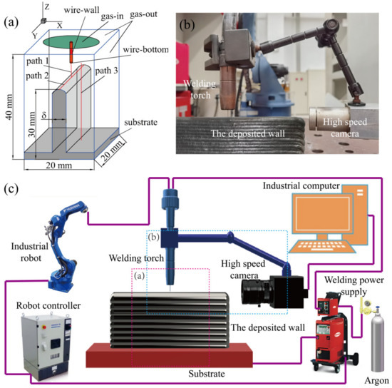
To verify the numerical calculation results, the WAAM experiments were carried out using the same condition in the numerical model. The thickness values identical to the numerical models were mainly obtained by adjusting the welding speed. The experimental system was set up with a Fronius TPS 400i welding power supply (SIMECO GROUP LTD, Hongkong, China) and a MOTOMAN-MA2010 robot (YASKAWA Global LTD., Tokyo, Japan). A high-speed camera (Balser acA1920-40gc, Basler Vision Technology (Beijing) Co., Ltd., Beijing, China) was used to collect the arc topography information, as shown in Figure 1. To keep a constant distance from the camera to the arc centre, the camera was fixed to the welding torch through the bracket in front of the welding torch. The computational domain with dimensions of 20 mm × 20 mm × 40 mm includes five parts: the welding nozzle, feeding wire, shielding gas regions, single-pass multi-layer wall, and the substrate, as shown in Figure 1. A fine grid domain is used underneath the wire, and the minimum mesh size is 0.1 mm; the coarse grid domain with gradually increasing mesh size (0.1–0.5 mm) is adopted in another field. The diameter of the GMAW welding nozzle is 16 mm. The diameter of the wire anode is 1.2 mm, the distance from the wire tip to the upper surface of the wall is 5 mm, and the size of the substrate used as the cathode is 20 mm × 20 mm × 5 mm. To avoid the arc covering the substrate and affecting the calculation results, the height of the single-pass multi-layer wall is set to 25 mm. The deposition current is 150 A with a voltage of 22 V, the feeding speed is 4.6 mm, and the other deposition parameters are shown in Table 1. The commercial Ar is used for the shielding gas with a flow rate of 20 L/min. The thermodynamic and transport properties of Ar are taken from Murphy [19]. The material of the feeding wire and the substrate is 316L stainless steel, and its thermo-physical properties are described in the literature [14]. To study the effect of wall thickness on the arc shape, temperature field, velocity field, current density, and electromagnetic force distribution under steady-state conditions, 3D numerical models were established, including ten groups of single-pass multi-layer walls with different thicknesses (1 mm, 2 mm, 3 mm, 4 mm, 5 mm, 6 mm, 8 mm, 10 mm, 12 mm, and 14 mm) and a single bead depositing (equal to δ = +∞). Boundary conditions are shown in Table 2.


where is the gas flow, is the gas inlet area, is the convective heat transfer coefficient, is the metal surface temperature, is the Stefan–Boltzmann constant, is the surface radiation emissivity, and is the normal vector.

Figure 1.
The schematic diagram of the single-pass multi-layer WAAM experiments: (a) the single-pass multi-layer WAAM system; (b) the computational domain and boundary conditions; (c) assembly.

Table 1.
Deposition parameters.
Table 1.
Deposition parameters.
| No. | Welding Speed (mm/s) | Shielding Gas Flow Rate (L/min) | Designed δ (mm) | Measured δ (mm) |
|---|---|---|---|---|
| 1 | 24 | 20 | 1 | 1.4 |
| 2 | 22 | 20 | 2 | 1.9 |
| 3 | 18 | 20 | 3 | 3.1 |
| 4 | 10 | 20 | 4 | 4.2 |
| 5 | 8 | 20 | 5 | 5.1 |
| 6 | 4.5 | 20 | 6 | 6.2 |
| 7 | 3.5 | 20 | 8 | 8.1 |
| 8 | 2.8 | 20 | 10 | 10.2 |
| 9 | 2.5 | 20 | 12 | 12.2 |
| 10 | 2 | 20 | 14 | 14.3 |
| 11 | 4 | 20 | +∞ (a single bead depositing) | +∞ (a single bead depositing) |

Table 2.
Boundary conditions.
Table 2.
Boundary conditions.
| Boundaries | (m/s) | T (K) | (V) | (Wb/m) |
|---|---|---|---|---|
| wire-bottom | — | 3000 | ||
| wire-wall | — | coupled | coupled | |
| gas-in | 300 | |||
| gas-out | — | 300 | 0 | |
| workpiece | — |
3. Results and Discussion
3.1. The Arc Shape and Temperature Fields
The left side of the images in Figure 2 shows the calculated temperature field on the XOZ plane under different single-pass multi-layer wall thicknesses. When δ is less than 6 mm, the wall is entirely covered by the arc in the diameter Φ of 7.6 mm and elongated downward along the wall side in the deposition direction. The thinner the single-pass multi-layer wall, the longer the arc is pulled along the sidewall. This is because the speed of the arc plasma is fast in the arc centre area and slow in the outer arc area. The larger the area of the arc heating on the sidewall, the longer the high-temperature residence time of the as-deposited metal, and the deeper the effect on the microstructure and properties of the deposited wall. When the single-pass multi-layer wall thickness δ is 1 mm, the arc is elongated most noticeably because the wall thickness is smaller than the diameter of the welding wire, and the arc plasma with higher velocity in the centre of the arc flows directly to the bottom. When δ locates in 8–14 mm, the arc can only cover a limited area of the upper surface of the wall. The arc heat was mainly acting on the surface of the as-depositing wall and had little influence on the wall side. With the increase in the wall thickness, the arc shape is close to the bell shape of the single bead deposition, because the top surface of the wall is close to the plane shape for the thicker walls. Owing to the decrease in the welding speed, a wide wall width can be obtained under the same parameters, which means there is enough support for the cylindrical arc. Considering the high ion flow speed, after shooting on the surface, they will naturally spread out around the circumference. As a result, a bell-shaped arc was observed.
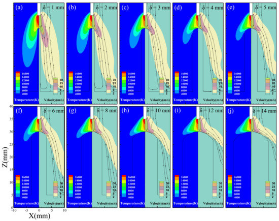
Figure 2.
The temperature and velocity field of the arc on the XOZ plane: (a) δ = 1 mm, (b) δ = 2 mm, (c) δ = 3 mm, (d) δ = 4 mm, (e) δ = 5 mm, (f) δ = 6 mm, (g) δ = 8 mm, (h) δ = 10 mm, (i) δ = 12 mm, and (j) δ = 14 mm.
Comparing the calculation results in [28], the arc is also elongated along the sidewall with the increase in deposition layers. The differences in additive current and wire diameter between [28] and this study result in the degree of the arc contraction, elongation along the sidewall, and the arc peak temperature. Figure 3 shows the arc topographies collected by the camera (left side of the images) and calculated arc profile (6000 K isotherm on the arc temperature field result). It can be seen from Figure 3 that when the wall thickness is smaller than the arc diameter Φ, the arc elongation distance along the sidewall decreases with the increase in wall thickness. When the wall thickness is greater than the arc diameter Φ, the arc does not elongate along the sidewall, and this is consistent with the law of simulation calculation. Moreover, the arc profiles collected under different wall thicknesses are in agreement with the arc profiles calculated by simulation, which indicates that the experimental results are consistent with the calculations.
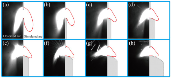
Figure 3.
Comparison of the observed and simulated arc profiles at different wall thicknesses: (a) δ = 1 mm, (b) δ = 2 mm, (c) δ = 4 mm, (d) δ = 5 mm, (e) δ = 6 mm, (f) δ = 8 mm, (g) δ = 10 mm, (h) δ = 14 mm.
3.2. Velocity Fields
The velocity fields are shown in the right half of the images in Figure 2. The closer to the centre of the arc, the higher the velocity, because the strong electromagnetic force accelerated the ionised argon gas at high temperatures with high current density [29]. The creamy-white area of the velocity field indicates that the gas velocity is higher than 2 m/s. From Figure 2a–f, it can be seen that when the wall thickness δ is smaller than the arc diameter Φ during the single deposition, the thinner the wall, the larger the area of the sidewall covered by the gas. The gas flow rate is higher than 2 m/s, which corresponds to a shielding gas flow rate of 20 L/min. Thus, the protective effect of the shielding gas will be better for the thinner walls. From Figure 4a,b, when δ = 5.1 mm and 6.2 mm (corresponding to δ slightly less than Φ), the sidewalls have no pores with a good formation. Owing to the covering of the top surface and side surface by the elongated arc, adequate protection of the sidewall can be expected, which is consistent with the above analysis. However, in the WAAM experiments, when δ is less than 4 mm, it will be hard to fabricate the wall because of the massive heat input.
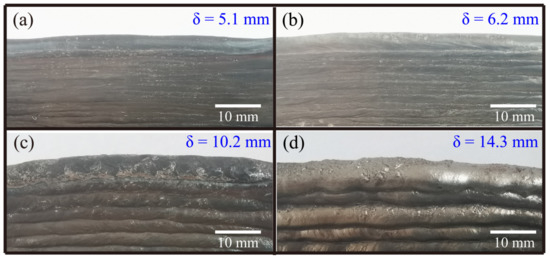
Figure 4.
Photographs of the sidewall forming of the deposited wall with different thicknesses: (a) δ = 5.1 mm, (b) δ = 6.2 mm, (c) δ = 10.2 mm, and (d) δ = 14.3 mm.
Figure 2g–j shows that when δ varies from 8 to 14 mm, the wall thickness is larger than the arc diameter Φ, and the shielding gas can only cover a part area of the upper surface of the deposited wall, which may lead to poor protection on the sides of the molten pool, resulting in the pores on the sidewall. As can be seen from Figure 4c,d, when δ = 10.2 mm and 14.3 mm, there are pores on the sidewall. Hence, to obtain a suitable gas shielding effect on the sidewall, an oscillate strategy of the welding torch should be adopted. Compared with the case of δ < Φ, it can be seen that when δ is slightly less than Φ, the forming quality of the deposited wall is the best. From Figure 2, the angles between the creamy-white area and the sidewall gradually increase with the rise in wall thickness. The reason is that with the increase in the wall thickness, the strong blocking effect of the upper surface causes the plasma flow divergence to both sides.
3.3. The Arc Parameters Distribution along the Characteristic Path
The distribution features of the various parameters (such as shape, temperature, current density, and electromagnetic force) of the arc on the three typical paths (shown in Figure 1) were analysed. Figure 5 shows the temperature distribution curves along path 1 for the different wall thicknesses. The same temperature distribution trend as that in Figure 5 is also found in [28], which is mainly caused by the different degrees of contraction of the arc at the electrode of the feeding wire and the electrode of the deposition layer. It can be seen that there is a large temperature gradient in the range of about 0.5 mm from the anode and cathode surfaces (near the anode: about 44,333.3 K/mm; near the cathode: about 26,033.3 K/mm), which is due to the significant difference in thermophysical parameters between the shielding gas Ar and the electrodes [29]. Since the wire termination acting as the anode is smaller than the cathode area on the upper surface of the deposited wall, the arc centre peak temperature is near the anode. Moreover, with the increase in the wall thickness, the peak temperature of the arc centre gradually decreases from 26,024 K to 21,100 K and then tends to be flat. When δ is smaller than the Φ during the single bead deposition, the arc can completely cover the upper surface in the width direction. As the wall thickness increases, the degree of arc shrinkage in the width direction gradually decreases. The current density in the arc centre also decreases slowly, resulting in a decrease in the temperature in the arc centre. When the wall thickness δ is greater than the arc diameter Φ, the arc can only cover a part of the area of the upper surface of the deposited wall in the width direction. With the increase in the wall thickness, the cathode area on the surface of the deposited wall is almost unchanged, so the latter part of the temperature curve tends to be gentle. In addition, it also can be seen that when the wall thickness varies from 8 to 14 mm, the peak temperature in the arc centre increases slightly. This is because the cathode area on the upper surface decreases when the curvature radius of the upper surface increases. Usually, a larger wall thickness value means a larger curvature radius of the upper surface.
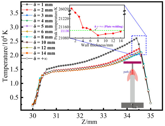
Figure 5.
Temperature distribution curves along path 1 with different wall thicknesses.
Figure 6a–c shows the distribution diagrams of temperature, current density, and electromagnetic force on path 2, and the overall change trend is consistent with that of [28]. The temperature distribution of the arc on path 2 is almost unchanged (for δ > 1 mm), indicating that the wall thickness has little effect on the temperature distribution of path 2, as shown in Figure 6a. When the wall thickness is 1 mm, the maximum temperature of the arc centre is significantly higher than other wall thicknesses. This is because the arc shrinks considerably in the wall thickness direction, so the peak temperature of the arc centre in path 2 with a wall thickness of 1 mm is significantly higher than that of other wall thicknesses.
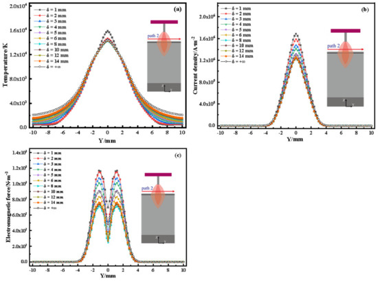
Figure 6.
Distribution of main parameters on path 2: (a) temperature; (b) current density; (c) electromagnetic force.
It can be seen from Figure 6b,c that the current density and electromagnetic force are both 0 in the section of path 2 that is greater than 3.8 mm from the arc centre, indicating that the radius of the arc corresponding to different wall thicknesses on path 2 is about 3.8 mm (almost equal to the arc radius Φ/2 of plate welding). It hardly changes with the wall thickness.
It can be seen from Figure 6c that the electromagnetic force has a symmetrical bimodal distribution on path 2, which is because the current flowing to the cathode will generate a self-generated magnetic field. The inward and downward magnetic fields will be developed under the interaction between the self-generated magnetic field and the current density [29]. The inward electromagnetic forces at the arc centre cancel each other out, so there is a valley in the electromagnetic force at the arc centre.
From the changes in peak current density, peak electromagnetic force, and valley electromagnetic force in Figure 6b,c, it can be seen that when the wall thickness δ is less than the arc diameter Φ during the single bead deposition, the peak current density, peak electromagnetic force, and valley electromagnetic force gradually decrease with the increase in the wall thickness. When the wall thickness δ is greater than the arc diameter Φ, the peak current density, peak electromagnetic force, and valley electromagnetic force gradually increase with the increase in the wall thickness.
This is because when the wall thickness δ is less than the arc diameter Φ, the arc completely covers the upper surface of the deposited wall. At this time, the thinner the wall thickness, the higher the degree of arc shrinkage along the width direction, which will increase the peak current density, peak electromagnetic force, and valley electromagnetic force of the arc on path 2. When the wall thickness δ is greater than the arc diameter Φ, the arc can only cover a partial area on the upper of the deposited wall. At this time, the thicker the wall, the smaller the cathode area on the upper surface of the deposited wall, resulting in the increase in the peak current density, peak electromagnetic force, and valley electromagnetic force of the arc on path 2, which is closer to the situation of the single bead deposition.
Figure 7a–c displays the distribution of arc temperature, current density, and electromagnetic force on path 3. It can be seen that with the increase in wall thickness, the temperature, current density, and electromagnetic force along path 3 gradually decrease; the main reason is that the thicker the wall and the farther path 3 is from the arc centre, the lower the temperature, current density, and electromagnetic force. Figure 7a,b shows that when the wall thickness δ is less than the arc diameter Φ, the temperatures are higher than the gas ionisation temperature (6000 K) along path 3, and the current density is not zero in the section 3–12 mm away from the upper surface near the sidewall. This indicates that when the wall thickness δ varies from 1 to 6 mm, the arc is elongated along the sidewall (about 3–12 mm), consistent with the actual measurements in Figure 3. It can be seen from Figure 6b,c that when δ is greater than the arc diameter Φ, the current density and electromagnetic force are almost 0, indicating that the arc can only cover a local area on the upper surface of the deposition wall in this case, which is consistent with the analysis results in Figure 2, Figure 3 and Figure 4.
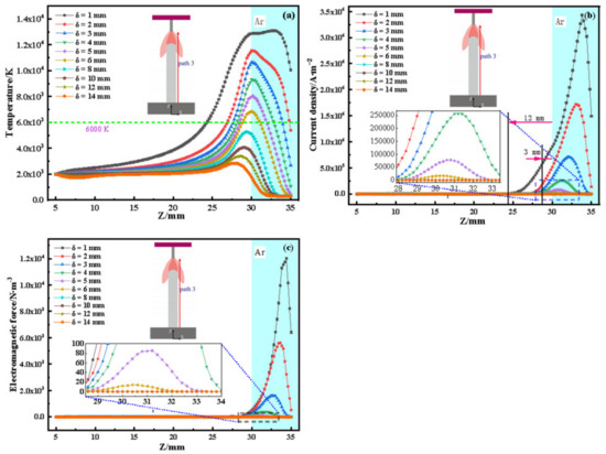
Figure 7.
Distribution of main parameters on path 3: (a) temperature; (b) current density; (c) electromagnetic force.
4. Conclusions
To fill the research gap and provide a theoretical basis for the matching selection of process parameters and wall thickness in WAAM applications, we established a set of 3D numerical models of single-pass multi-layer walls with different thicknesses in the WAAM process. The calculated results of arc shape and stability agree with the experimental results. Through comparative analysis, the following conclusions are drawn:
- (1)
- The length of the arc along the sidewall decreases with the increase in the wall thickness, and the arc shape tends to be bell-shaped. The wall thickness has little influence on the temperature, velocity, current density, and electromagnetic force distribution along the welding direction, which is similar to that of the plate welding. The coverage of shielding gas on the sidewall decreases with the increase in wall thickness. When δ is slightly less than Φ, the forming quality of the deposited wall is the best.
- (2)
- When δ < Φ, the peak temperature of the arc centre, the peak current density, and peak and valley electromagnetic force along the welding direction decrease with the increase in the wall thickness, and the increase in wall thickness will lead to the reduction in arc contraction.
- (3)
- When δ > Φ, the peak temperature of the arc centre, the peak current density, and peak and valley electromagnetic force along the welding direction increase slowly with the increase in wall thickness, and similar to the case of plate welding, the small cathode area on the top surface of the wall will lead to a weak trend of the arc contraction.
Author Contributions
Conceptualization, C.Z. and X.Z.; methodology, J.W. and M.Z.; software, C.Z. and Y.H.; formal analysis, C.Z.; data curation, J.W.; writing—original draft preparation, C.Z. and X.Z.; writing—review and editing, X.Z.; visualization, C.Z.; supervision, K.W.; project administration, Y.P.; funding acquisition, K.W. All authors have read and agreed to the published version of the manuscript.
Funding
This research was funded by [Natural Science Foundation of the Jiangsu Higher Education Institutions of China] grant number [21KJB430009], [Innovation Fund for key laboratories of the Ministry of industry and information technology] grant number [CXJJ-2020112701], [China Postdoctoral Science Foundation] grant number [2021M691588] and [Natural Science Foundation of Jiangsu Province] grant number [BK20210351].
Institutional Review Board Statement
Not applicable.
Informed Consent Statement
Not applicable.
Data Availability Statement
The raw/processed data required to reproduce these findings cannot be shared at this time as the data also form part of an ongoing study.
Acknowledgments
The authors gratefully acknowledge the Qing Lan Project of Colleges and Universities in Jiangsu Province and the Taizhou “Fengcheng Talents” Young Scientific and Technological Talents Lifting Project.
Conflicts of Interest
The authors declare no conflict of interest.
References
- Williams, S.W.; Martina, F.; Addison, A.C.; Ding, J.; Colegrove, P. Wire + Arc Additive Manufacturing. Mater. Sci. Technol. 2016, 32, 641–647. [Google Scholar]
- Cunningham, C.; Flynn, J.; Shokrani, A.; Dhokia, V.; Newman, S. Invited review article: Strategies and processes for high quality wire arc additive manufacturing. Addit. Manuf. 2018, 22, 672–686. [Google Scholar] [CrossRef]
- Ortega, A.G.; Galvan, L.C.; Deschaux-Beaume, F.; Mezrag, B.; Rouquette, S. Effect of process parameters on the quality of aluminium alloy Al5Si deposits in wire and arc additive manufacturing using a cold metal transfer process. Sci. Technol. Weld. Join. 2018, 23, 316–332. [Google Scholar] [CrossRef]
- Ikram, A.; Chung, H. Numerical simulation of arc, metal transfer and its impingement on weld pool in variable polarity gas metal arc welding. J. Manuf. Process. 2021, 64, 1529–1543. [Google Scholar]
- Manqing, C.H.E.N.G.; Yanli, A.N.; Huayun, D.U.; Yinghui, W.E.I.; Ding, F.A.N. Effect of current changes on velocity and temperature profiles of GTAW arc. Trans. China Weld. Inst. 2010, 31, 33–37. [Google Scholar]
- Bachmann, B.; Kozakov, R.; Gött, G.; Ekkert, K.; Bachmann, J.-P.; Marques, J.-L.; Schöpp, H.; Uhrlandt, D.; Schein, J. High-speed three-dimensional plasma temperature determination of axially symmetric free-burning arcs. J. Phys. 2013, 46, 125203. [Google Scholar] [CrossRef]
- Hsu, K.C.; Etemadi, K.; Pfender, E. Study of the freeburning highintensity argon arc. J. Appl. Phys. 1983, 54, 1293. [Google Scholar]
- Nahed, C.; Gounand, S.; Medale, M. A numerical study of the effects of cathode geometry on tungsten inert gas type electric arcs. Int. J. Heat Mass Transf. 2022, 182, 121923. [Google Scholar] [CrossRef]
- Hu, J.; Tsai, H.L. Heat and mass transfer in gas metal arc welding. Part I: The arc. Int. J. Heat Mass Transf. 2007, 50, 833–846. [Google Scholar] [CrossRef]
- Hu, J.; Tsai, H.L. Heat and mass transfer in gas metal arc welding. Part II: The metal. Int. J. Heat Mass Transf. 2007, 50, 808–820. [Google Scholar] [CrossRef]
- Cadiou, S.; Courtois, M.; Carin, M.; Berckmans, W.; Le Masson, P. 3D heat transfer, fluid flow and electromagnetic model for cold metal transfer wire arc additive manufacturing (Cmt-Waam). Addit. Manuf. 2020, 36, 101541. [Google Scholar] [CrossRef]
- Zhou, X.; Zhang, H.; Wang, G.; Bai, X. Three-dimensional numerical simulation of arc and metal transport in arc welding based additive manufacturing. Int. J. Heat Mass Transf. 2016, 103, 521–537. [Google Scholar] [CrossRef]
- Zhou, X.; Tian, Q.; Du, Y.; Zhang, Y.; Bai, X.; Zhang, Y.; Zhang, H.; Zhang, C.; Yuan, Y. Investigation of the effect of torch tilt and external magnetic field on arc during overlapping deposition of wire arc additive manufacturing. Rapid Prototyp. J. 2020, 27, 1355–2046. [Google Scholar] [CrossRef]
- Wang, X.; Luo, Y.; Chi, L.; Fan, D. Numerical investigation of transport phenomena of arc plasma in argon-oxygen gas mixture. Int. J. Heat Mass Transf. 2020, 154, 119708. [Google Scholar] [CrossRef]
- Wang, L.L.; Lu, F.G.; Wang, H.P.; Murphy, A.; Tang, X.H. Effects of shielding gas composition on arc profile and molten pool dynamics in gas metal arc welding of steels. J. Phys. D Appl. Phys. 2014, 47, 465202. [Google Scholar] [CrossRef]
- Murphy, A.B.; Tanaka, M.; Yamamoto, K.; Tashiro, S.; Sato, T.; Lowke, J.J. Modelling of thermal plasmas for arc welding: The role of the shielding gas properties and of metal vapour. J. Phys. D Appl. Phys. 2009, 42, 194006. [Google Scholar] [CrossRef]
- Savaş, A.; Ceyhun, V. Finite element analysis of GTAW arc under different shielding gases. Comput. Mater. Sci. 2011, 51, 57–71. [Google Scholar]
- Xiao, L.; Fan, D.; Huang, J.-K. Numerical Study on Arc Plasma Behaviors in GMAW with Applied Axial Magnetic Field. J. Phys. Soc. Jpn. 2019, 88, 074502. [Google Scholar]
- Han, Y.; Chen, J.; Li, L.; Wang, L.; Wu, C. Numerical Investigation of Arc-Pool-Metal Vapor Behavior in GTAW with an External Magnetic Field. Metals 2020, 10, 1199. [Google Scholar]
- Wang, L.; Chen, J.; Wu, C. Numerical investigation on the effect of process parameters on arc and metal transfer in magnetically controlled gas metal arc welding. Vacuum 2020, 177, 109391. [Google Scholar] [CrossRef]
- Wang, L.; Chen, J.; Wu, C.; Luan, S. Numerical analysis of arc and droplet behaviors in gas metal arc welding with external compound magnetic field. J. Mater. Process. Technol. 2020, 282, 116638. [Google Scholar] [CrossRef]
- Wang, X.; Luo, Y.; Wu, G.; Chi, L.; Fan, D. Numerical Simulation of Metal Vapour Behavior in Double Electrodes TIG Welding. Plasma Chem. Plasma Process. 2018, 38, 1095–1114. [Google Scholar] [CrossRef]
- Kanemaru, S.; Sasaki, T.; Sato, T.; Era, T.; Tanaka, M. Study for the mechanism of TIG-MIG hybrid welding process. Weld. World 2015, 59, 261–268. [Google Scholar] [CrossRef]
- Wu, D.; Huang, J.; Kong, L.; Hua, X.; Wang, M. Coupled mechanisms of arc, weld pool and weld microstructures in high speed tandem TIG welding. Int. J. Heat Mass Transf. 2020, 154, 119641. [Google Scholar] [CrossRef]
- Bai, X.; Colegrove, P.; Ding, J.; Zhou, X.; Diao, C.; Bridgeman, P.; Hönnige, J.R.; Zhang, H.; Williams, S. Numerical analysis of heat transfer and fluid flow in multilayer deposition of PAW-based wire and arc additive manufacturing. Int. J. Heat Mass Transf. 2018, 124, 504–516. [Google Scholar] [CrossRef]
- Zhao, W.; Wei, Y.; Long, J.; Chen, J.; Liu, R.; Ou, W. Modeling and simulation of heat transfer, fluid flow and geometry morphology in GMAW-based wire arc additive manufacturing. Weld. World 2021, 20, 1571–1590. [Google Scholar] [CrossRef]
- Choudhury, S.S.; Marya, S.K.; Amirthalingam, M. Improving arc stability during wire arc additive manufacturing of thin-walled titanium components. J. Manuf. Processes 2021, 66, 53–69. [Google Scholar] [CrossRef]
- Zhou, X.; Zhang, H.; Wang, G.; Bai, X. Simulation of the influences of surface top ography of dep osited layer on arc shap e and state in arc based additive forming. Acta Phys. Sin. 2016, 65, 331–342. [Google Scholar]
- Xinxin, W.; Ding, F.; Jiankang, H.; Yong, H. Numerical Simulation of Heat Transfer and Fluid Flow for Arc-weld Pool in TIG Welding. J. Mech. Eng. 2015, 50, 69–78. [Google Scholar]
Publisher’s Note: MDPI stays neutral with regard to jurisdictional claims in published maps and institutional affiliations. |
© 2022 by the authors. Licensee MDPI, Basel, Switzerland. This article is an open access article distributed under the terms and conditions of the Creative Commons Attribution (CC BY) license (https://creativecommons.org/licenses/by/4.0/).