Article

Effects of Process Parameters on Microstructure and Mechanical Properties of Semi-Solid Al-7Si-0.5Mg Aluminum Alloy by Gas Induced Semi-Solid Process

1
Key Laboratory for Liquid-Solid Structural Evolution and Processing of Materials, Ministry of Education, Shandong University, Jinan 250061, China
2
School of Materials Science and Engineering, Shandong University, Jinan 250061, China
3
Suzhou Institute, Shandong University, Suzhou 215123, China
4
Shandong Institute for Product Quality Inspection, Jinan 250102, China
5
ENSAM-Arts et Métiers Sciences and Technologies, LEM3 UMR CNRS 7239, 4 Rue Augustin Fresnel, CEDEX 3, 57078 Metz, France
*
Authors to whom correspondence should be addressed.
Metals 2022, 12(10), 1600; https://doi.org/10.3390/met12101600
Submission received: 31 July 2022 / Revised: 15 September 2022 / Accepted: 17 September 2022 / Published: 25 September 2022
(This article belongs to the Special Issue Advances in Semi-solid Forming)

Abstract

:
Al-7Si-0.5Mg aluminum alloy semi-solid slurry with good spherical grains was prepared by gas induced semi-solid process (GISS) and the effects of both holding time and medium alloy addition on the microstructure of the semi-solid slurry were investigated. These two parameters have a great influence on the solid fraction, the size and the sphericity of the grains. With holding time increased from 85 s to 270 s, the solid phase fraction of the semi-solid slurry decreased from ~0.77 to ~0.67, the average grain size increased from ~95 μm to ~225 μm and the average shape factor decreased from ~0.80 to ~0.33. When medium alloy addition varied in the range of 0.5–2.0 wt%, a better slurry microstructure was obtained at about 1.5 wt%. Compared with the conventional liquid die-casting, the semi-solid die-casting improved the mechanical properties of tensile bars; yield strength, tensile strength and elongation of tensile bars reached ~240 MPa, ~307 MPa and ~8.8% after heat treatment, respectively. In conclusion, GISS process can prepare the semi-solid slurry with uniform and round microstructure, and the semi-solid die-casting can improve mechanical properties of Al-7Si-0.5Mg aluminum alloy.

1. Introduction

Aluminum alloy parts manufactured by traditional liquid forming are prone to turbulent flow filling and air entrainment during the production process, resulting in defects such as shrinkage porosity, shrinkage cavities, pores and slag inclusions, which affect the mechanical properties of parts and limit the applications for aluminum alloys [1].
Compared with traditional liquid forming, when the high-viscosity melt moves forward smoothly during the filling process of semi-solid die-casting, the gas in the cavity is discharged smoothly and entrainment does not easily occur [2]. Due to the existence of solid phase, the shrinkage produced during the solidification process is small, and it is not easy to produce hole defects [3], so that the semi-solid forming products have high compactness and can be heat treated to improve the mechanical properties again [4,5]. Initially, semi-solid processing techniques, such as mechanical stirring method [5,6] and electromagnetic stirring method [7,8], were mainly used for experimental research with few industrial applications. In recent years, researchers have designed preparation methods with simple equipment and low cost, such as gas induced semi-solid process [9,10], self-inoculation method [11], rapid slurry forming [12,13], cooling ramp method [14], serpentine channel method [15], helical groove method [16], etc., and the formation mechanism of the slurry is also being continuously improved and developed [17,18].
GISS (gas induced semi-solid process) promotes nucleation by supercooling of graphite rod and high-purity argon gas, and then uniformly distributes the formed nuclei into the melt under the action of stirring to obtain semi-solid slurry. Wannasin et al. [10] prepared the A357 slurry structure with fine grains by controlling the gas flow rate, the ratio of the surface area of the graphite stirring head submerged into the melt to the melt volume, and the ventilation time. Kang et al. [2] studied the semi-solid structure of 7075 aluminum alloy and found that increasing the stirring speed and prolonging the stirring time within a certain range was conducive to the refinement and spheroidization of primary grains. Qi [3] studied the effect of gas flow on Al-8Si aluminum alloy slurry and believed that with the increase of gas flow, the critical nucleation energy required to form grains decreased, leading to an increased nucleation rate, which was beneficial to obtain more fine grains. Gao et al. [19] used orthogonal experiments to study the effects of gas flow, stirring temperature, stirring time and sampling temperature on the semi-solid microstructure, and found that stirring time and stirring temperature were the main factors affecting the microstructure, with a reliability of 95%.
There are many studies on the parameters such as the starting ventilation temperature, rotation speed, ventilation time and ventilation flow in the GISS method [20,21,22]. However, there is not much research on the effects of holding time and medium alloy addition on the microstructure evolution, although they have a great influence on the spheroidization and refinement process of the slurry. With the extension of holding time, the composition of the alloy will be homogenized due to atomic diffusion, resulting in the gradual disappearance of dendrite branching characteristics. The addition of master alloy increases nucleation particles to refine aluminum grains. This paper further investigates these two parameters.
A356 aluminum alloy is a typical cast aluminum alloy with a wide semi-solid temperature range, low temperature sensitivity and good fluidity. It is widely used in the automotive industry (cylinder head, wheel hub, frame), aerospace and other fields [23,24,25], but the A356 parts produced by traditional casting have a tensile strength of 255 MPa after T6 treatment [26], and their mechanical properties are poor, which cannot any longer meet the needs of lightweight automobiles. To solve this problem, researchers have taken many measures, such as changing alloy composition, choosing better refiners and modifiers, and optimizing the casting process and heat treatment (generating strengthening phases, such as Mg2Si).
In this paper, the Mg content is appropriately increased on the basis of A356 aluminum alloy, and mechanical properties are expected to be further improved. The GISS method is used to study the effects of holding time and medium alloy content on the microstructure of semi-solid slurry. Finally, combined with the die casting process, the microstructure and mechanical properties of traditional liquid die casting and semi-solid die casting were compared and analyzed.

2. Materials and Methods

2.1. Experimental Materials

The experimental alloy considered is a self-prepared Al-7Si-0.5Mg aluminum alloy. The raw materials were high-purity aluminum (4N), aluminum-magnesium alloy (Al-20 wt%Mg) and high-purity silicon (7N). The prepared melt mass was 2 kg. The samples were analyzed by LAB M12 direct reading spectrometer (SPECTRO, Kleve, Germany); the chemical composition is given in Table 1.

2.2. DSC Test

The liquid and solidus temperatures of the prepared materials were measured by NETZSCH-404c DSC device (NETZSCH, Selb, Germany). Sample mass was 19.06 mg, tested according to the set temperature program (heating rate 20 °C/min, cooling rate 20 °C/min, final temperature 700 °C). During the test, the thermocouple (K-type, with an accuracy of ±0.75%T) was placed in the crucible for monitoring and recording the temperature of the sample.

2.3. Slurry Preparation and Die-Casting

Al-7Si-0.5Mg aluminum alloy was melted in a KGPS-50/2.5 box resistance furnace (Jiande Xin’anjiang Electric Control Equipment Co., Ltd., Jiande, China) and degassed by hexachloroethane (C2Cl6) at 720 °C, then medium alloy (Al-5Ti-1B) was added into the melt at 680 °C for refining, and finally the molten aluminum was transferred to the GISS station to start pulping, as shown in Figure 1. This device is different from the previous GISS, the stirring rod can revolve, and the purpose is to improve uniformity of the melt and prepare a qualified slurry. Table 2 lists the detailed process parameters of the GISS process. Slurry taken during pulping process was quenched in water immediately. After pulping, slurry was transferred to Lijin DCC280 die-casting machine (LK TECH, Hong Kong, China). To investigate the possibility of heat treatment on the Al-7Si-0.5Mg alloys and to study the difference in the mechanical properties of the material processed by traditional die casting and semi-solid die casting, the final test bars were heat-treated (T6). Here, the T6 heat treatment refers to the solid solution at 540 °C for 30 min, followed by natural aging >6 h, and then artificial aging at 170 °C for 6 h.

2.4. Metallographic Observations and Tensile Tests

Samples used to analyze the microstructure were ground with P180-P1500 grit paper (Wuxi Gangxia Precision Sandpaper Factory, Wuxi, China), polished using 2.5–0.5 µm diamond paste and etched with Keller’s etchant for 10–20 s. Then the microstructure was observed and recorded on a metallographic microscope (Zeiss Axio Vert A1, Oberkochen Germany). Solid fraction, average shape factor (F) and average grain size (D) of the slurry were counted by Image J software (version of 1.48, National Institutes of Health, Bethesda, MD, America), using the formulas as follows:
D = 4 A π
F = 4 π A P 2
where A is the area of grain measured by Image J, and P is the perimeter of grain. For F = 1 the grain is an ideal spherulite.
Optical micrographs were segmented using a thresholding-based histogram algorithm to separate objects (solid phase) from the background. Figure 2 shows an example of this segmentation process, where an optical micrograph (Figure 2a) was subjected to a thresholding-based histogram algorithm to separate the solid phase (bright phase) from the background (Figure 2b). After the binarization, the solid phase fraction could be calculated by the area ratio. In order to identify the boundaries of each solid grain, watershed segmentation method [27] was used (Figure 2c). In addition, a pre-flooding algorithm was used to exclude small grains which were thought to be formed during cooling from semi-solid slurry. A set of 20 optical images were selected per sample for the measurements.
The tensile properties were tested using a Zwick-Z250 universal testing machine (ZwickRoell, Ulm, Germany) with a tensile speed of 1 mm/min (GB T 6397-1986), as shown in Figure 3.

3. Results

3.1. DSC Tests

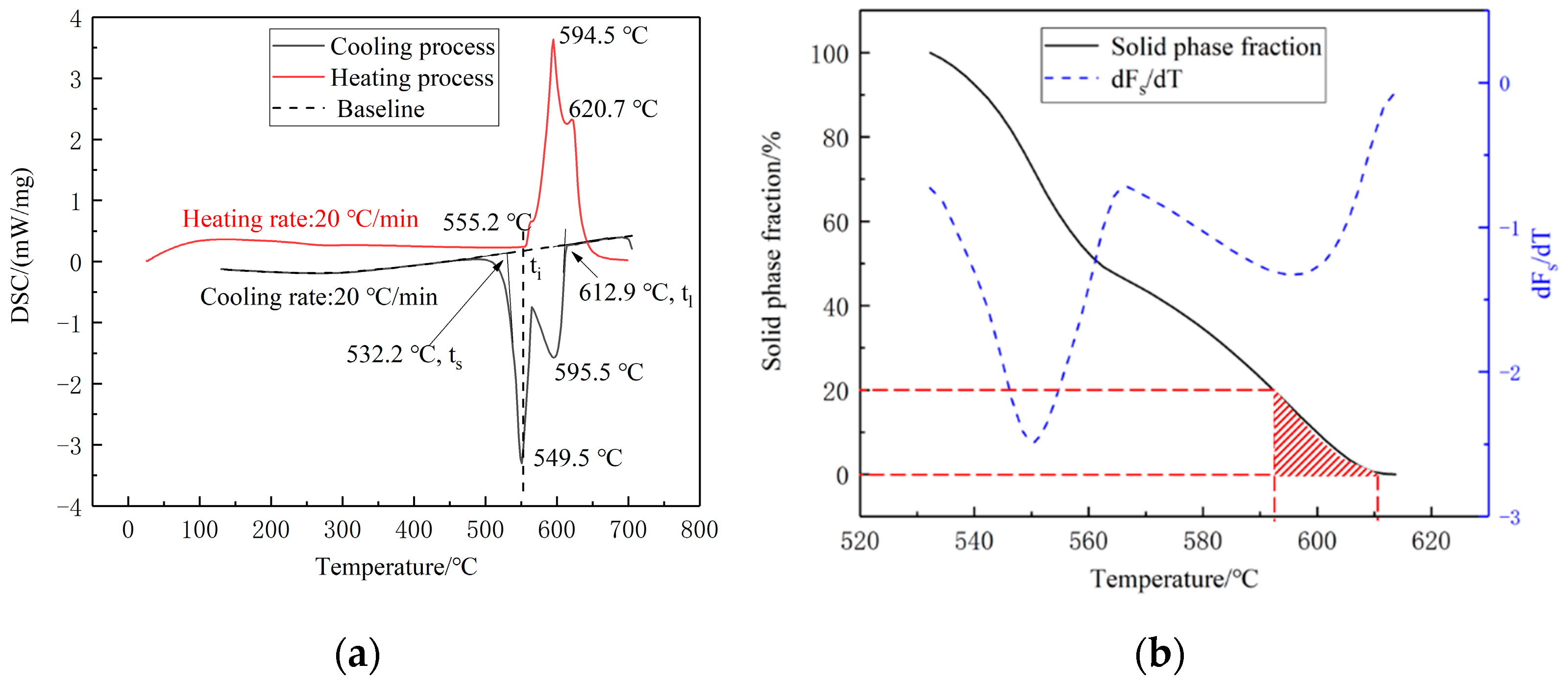
As shown in Figure 4a, the liquidus temperature of the Al-7Si-0.5Mg alloy was determined to be 612.9 °C during cooling from liquid state, and the crystallization enthalpy obtained from the calculation is Δ H c r y s t = 136.49 J/g. Then the DSC curve was integrated and converted to obtain the corresponding relationship between the solid fraction and the temperature, as shown in Figure 4b. It reveals relatively low temperature sensitivity for temperatures ranging from ~560 °C to ~610 °C. The working temperature window was chosen equal to 590–610 °C in order to get a proper low solid fraction (Fs, ranging from ~0.1 to ~0.25), which is favored for GISS method. The liquid and solidus temperatures were determined using the tangent method. We assume that the liquid fraction is proportional to the energy absorbed during the transformation. Using the method of partial areas, the solid fraction ( F s ) can be calculated by Equation (3):
F s = 1 S i S t o t a l = 1 t s t i f t d t t s t l f t d t
where S t o t a l is total area of peak, S i is the area of peak from solidus temperature ( t s ) to t i , f t is the measure of DSC signal per mass unit and baseline is already subtracted, as shown in Figure 4a.

3.2. Influence of Different Holding Time on Slurry Structure

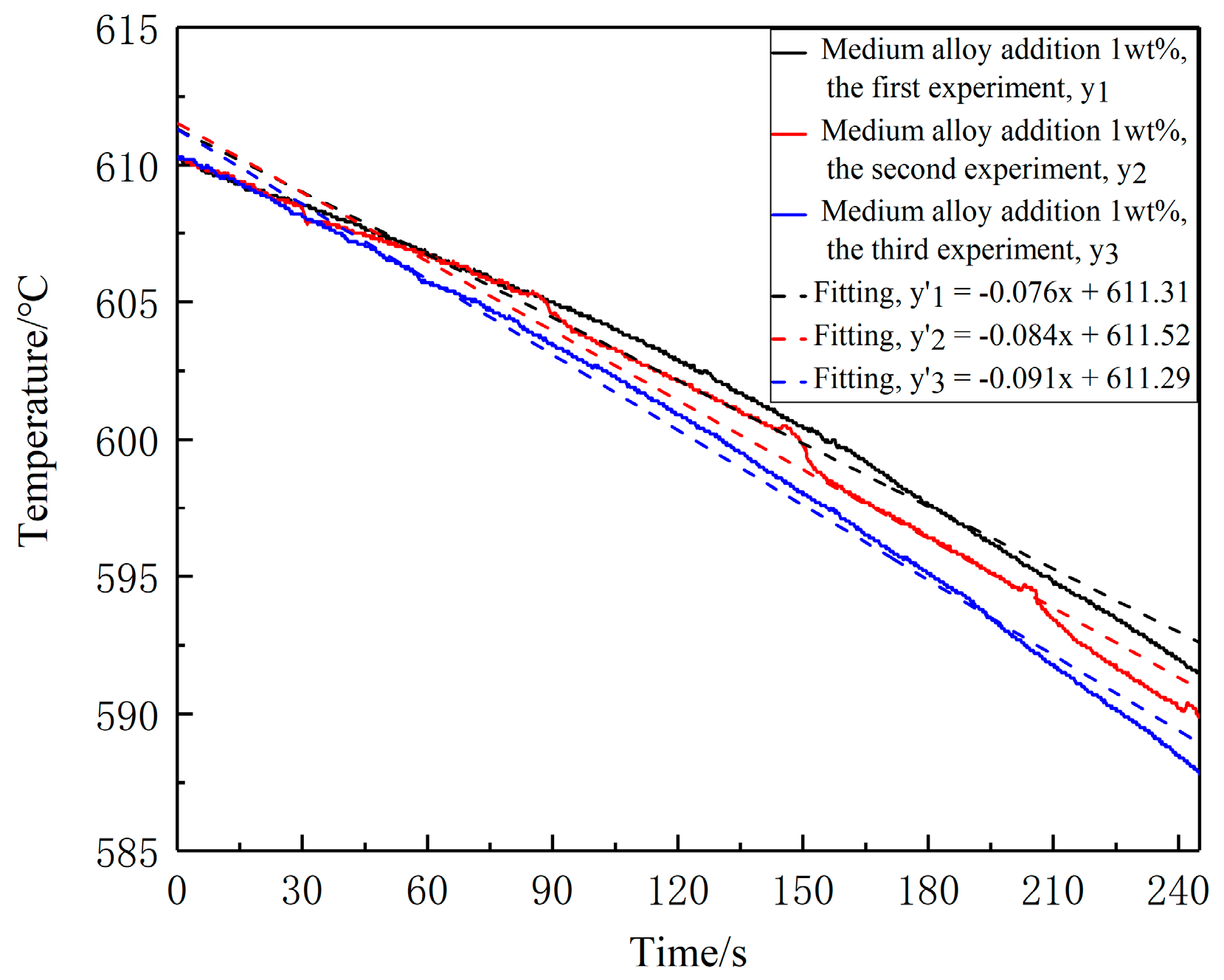
The temperature change of the semi-solid slurry during holding was recorded by thermocouple as shown in Figure 1. Three temperature curves were taken from various experiments to minimize the possibility of getting non-representative results due to the artificial interferences (Figure 5). The three curves in the figure correspond to the temperature changes during the holding stage when the holding time and medium alloy addition parameters are studied. From the figure, it can be calculated that during the holding period the average cooling rate is about 0.08 °C/s.
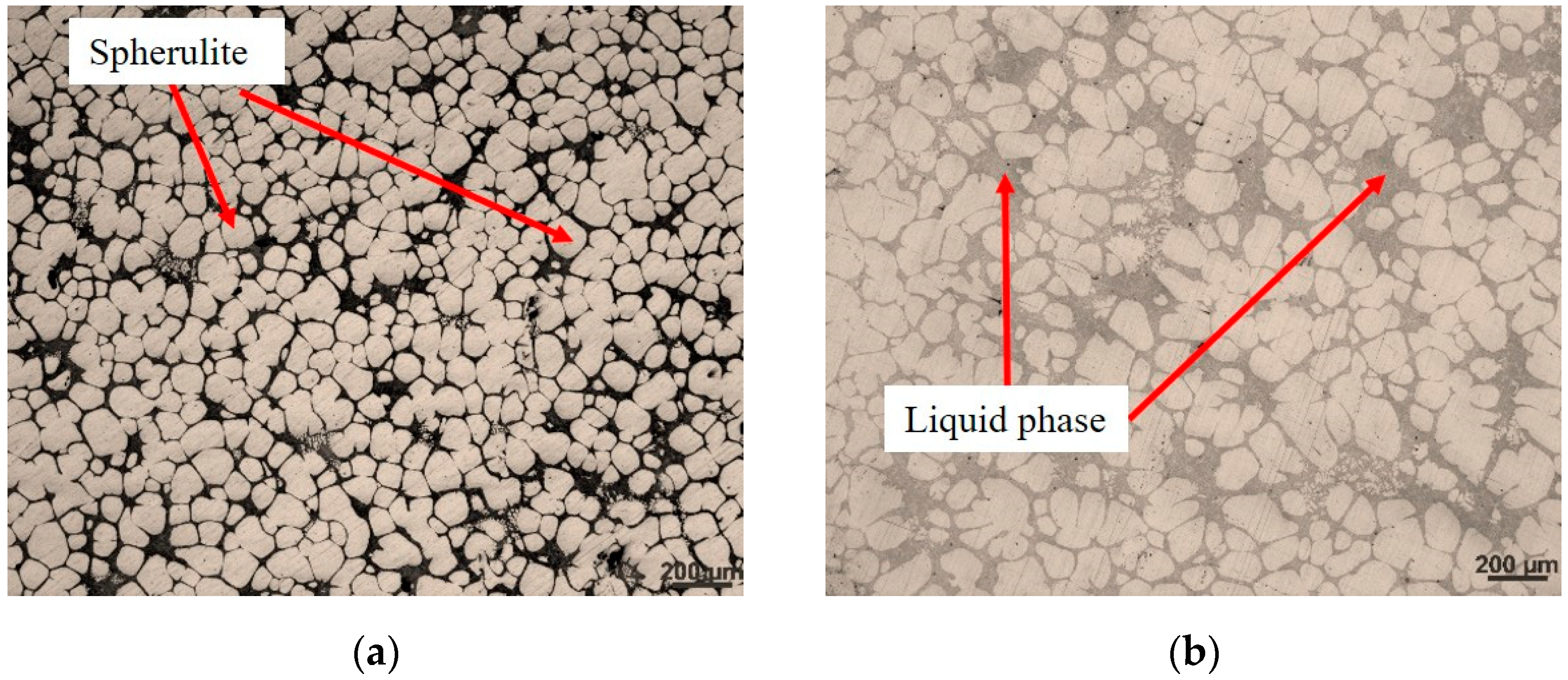
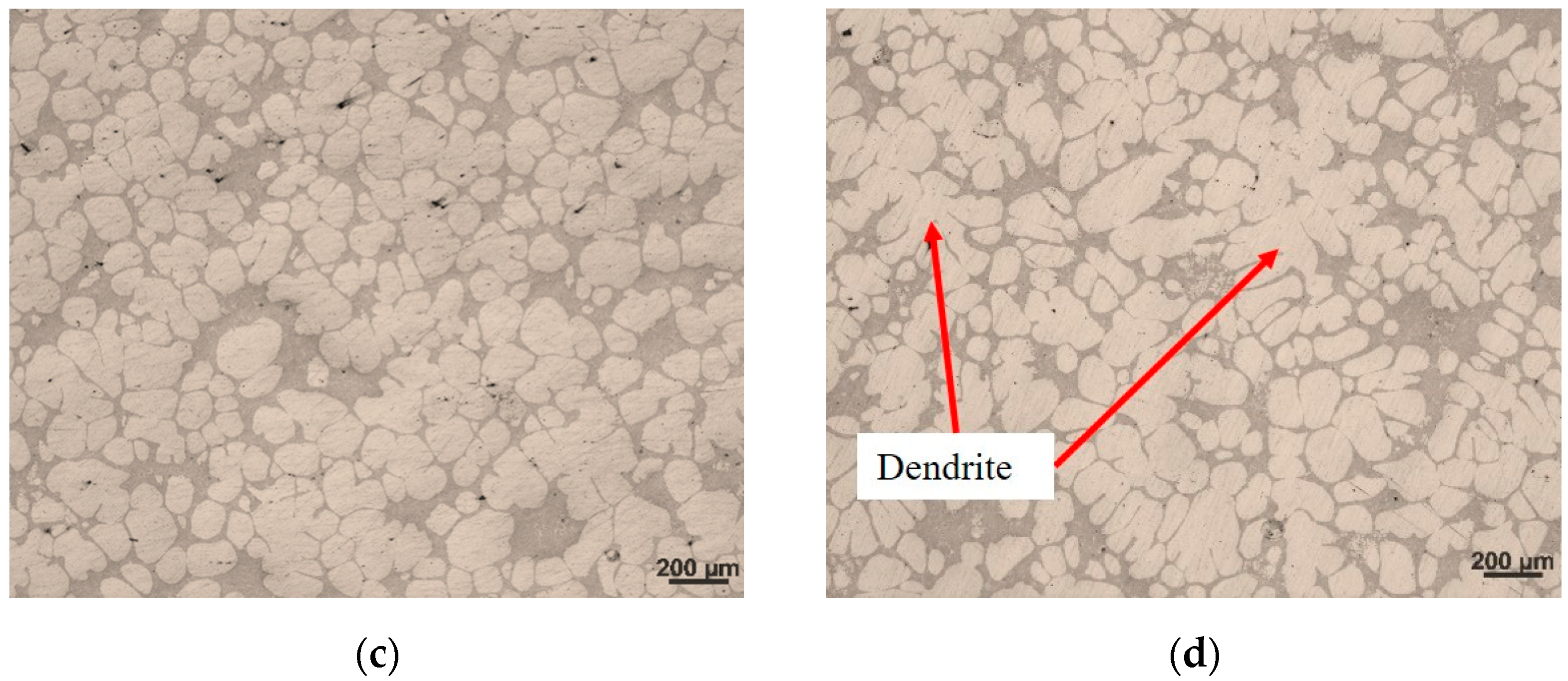
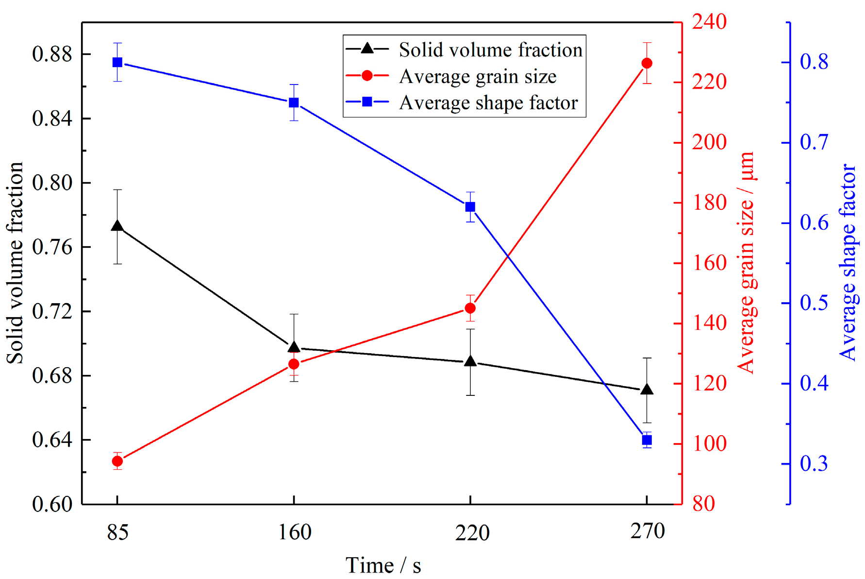
In order to investigate the influence of holding time, the microstructure of the material taken from the center of the crucible was observed by optical microscope. It can be seen from Figure 6 that with the increase of holding time, the primary phase continues to grow in the direction of dendrites, the average grain size is getting larger, the average shape factor is getting smaller and the solid fraction does not change much. When holding time is 270 s, as shown in Figure 6d, coarse dendrites appear in the microstructure and the spherical grains obtained in the early stage basically completely disappear.
Image J software is used to determine the solid fraction, average grain size and average shape factor of the Al-7Si-0.5Mg semi-solid slurry under different holding time, as shown in Figure 7. From the statistical results, it can be seen that with holding time increased from 85 s to 270 s, the solid phase fraction of the semi-solid slurry decreases from ~0.77 to ~0.67, the average grain size increases from ~95 μm to ~225 μm and the average shape factor reduces from ~0.80 to ~0.33. In conclusion, a relatively ideal semi-solid slurry structure can be obtained by holding for 85 s.

3.3. Effect of Medium Alloy Addition on Slurry Microstructure

Figure 8 shows the semi-solid microstructure of Al-7Si-0.5Mg aluminum alloy with different addition amounts of Al-5Ti-B medium alloy at 605 °C. It can be seen from Figure 8 that when the addition amount of medium alloy increases from 0.5 wt% to 1.5 wt%, the solid fraction, sphericity and grain density gradually increase, whereas the grain size gradually decreases. However, when the addition amount of medium alloy increases to 2%, the sphericity of grains decreases significantly, large rose-like and elongated grains appear and tiny fine secondary grains disperse in the liquid phase. These secondary grains are linked to secondary solidification stage when the semi-solid slurry leaves the GISS device, which will be discussed in Section 4.2. Although the secondary grains are smaller than the primary solid grains, they are counted for solid fraction measurements (except very small grains), because of the difficulties in their identification by image analysis.
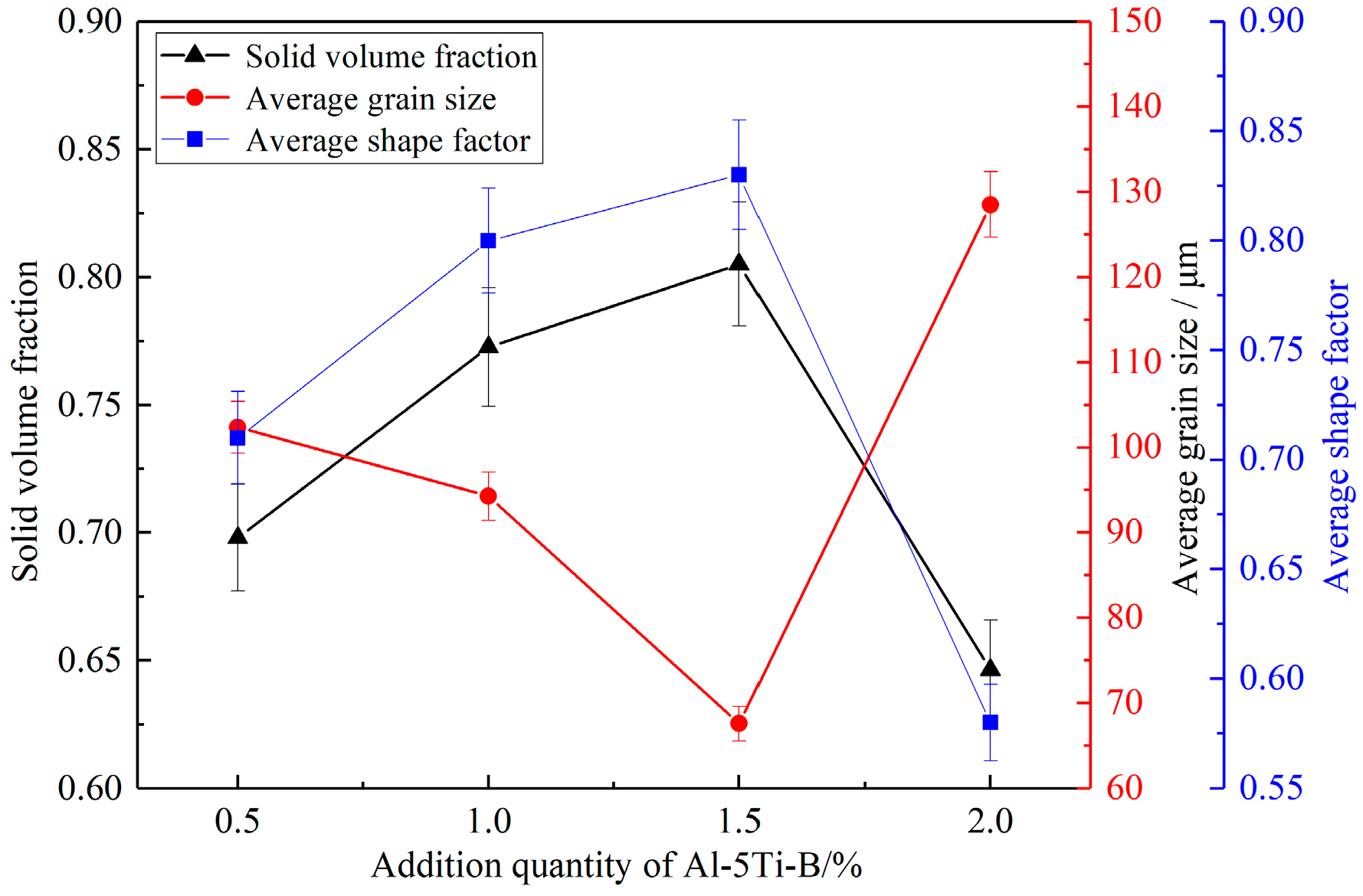
The quantitative results are shown in Figure 9. When the addition amount of medium alloy increases from 0.5 wt% to 1.5 wt%, the solid fraction increases from ~0.69 to ~0.80, the average grain size decreased from ~100μm to ~68 μm and the average shape factor changes from ~0.71 to ~0.83. When the addition amount of medium alloy increases from 1.5% to 2.0%, the solid fraction decreases by 20%, the average grain size increases by 90% and the average shape factor decreases by 30%. It can be seen that better sphericity and finer grain size were obtained at 1.5 wt% of Al-5Ti-B medium alloy within the experimental range, which is a suitable semi-solid slurry microstructure.

3.4. Test Bar Analysis

3.4.1. Mechanical Properties

Table 3 shows the performance comparison between liquid die-casting and semi-solid die-casting of Al-7Si-0.5Mg aluminum alloy in as-cast and T6 heat-treated states. It is found that mechanical properties of liquid die-cast Al-7Si-0.5Mg aluminum alloys are inferior to those of semi-solid die-cast Al-7Si-0.5Mg aluminum alloys in both as-cast and heat-treated states. The yield strength of Al-7Si-0.5Mg aluminum alloy GISS semi-solid die-casting is ~136 MPa, the tensile strength is ~266 MPa and the elongation is ~11.6%. After heat treatment, the yield strength increases to ~240 MPa, the tensile strength increases to ~307 MPa (yield strength and tensile strength are increased by 76% and 15%, respectively) and the elongation is reduced to ~8.8%. This indicates that the mechanical properties of test bars prepared by the GISS semi-solid die-casting process can be improved by heat treatment.
In addition, compared with traditional liquid die-casting, the yield strength and tensile strength of semi-solid die-casting are increased by 5% and 10%, respectively, for as cast, and by 86% and 27%, respectively, after heat treatment. After heat treatment, the elongation of liquid die-cast test bars after heat treatment decreased from ~11.2% to ~1.6%, which proved that the liquid die-casting test bars will expand gas and generate bubbles after heat treatment, which will seriously lead to the deformation of test bars. In conclusion, GISS semi-solid die-casting Al-7Si-0.5Mg aluminum alloy has obvious advantages over traditional liquid die-casting.

3.4.2. Fracture Analysis

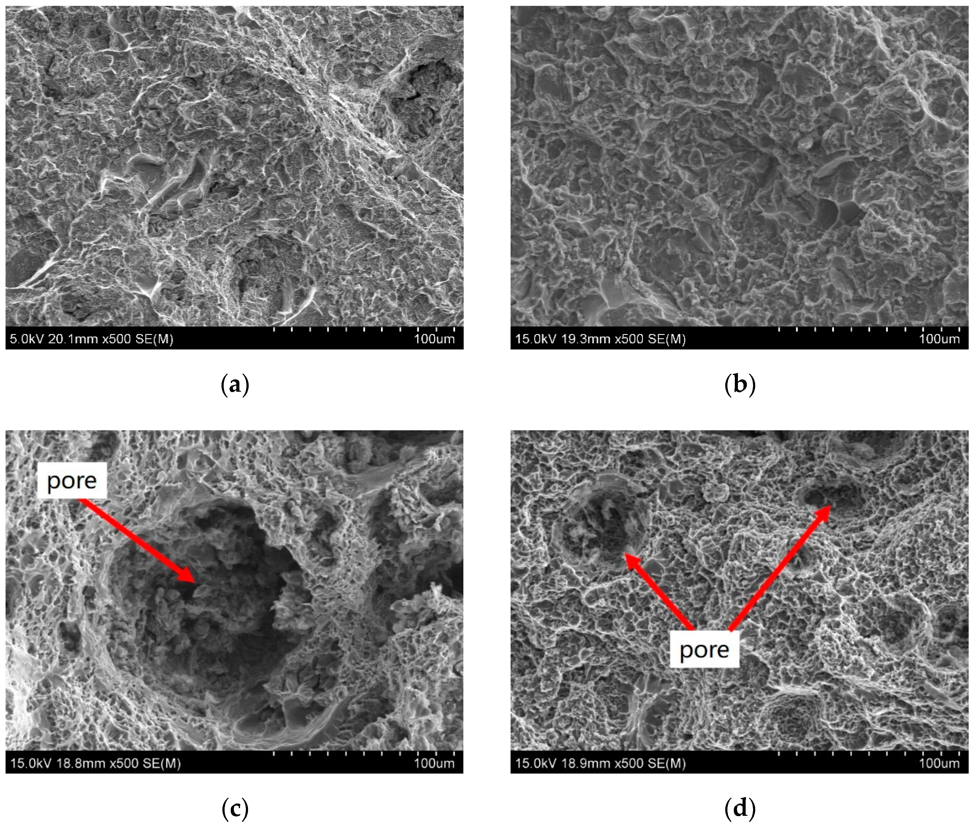
In order to investigate the fracture behavior of the samples treated at various conditions, Figure 10 compares the fracture mode of the as-cast and T6 specimens of traditional liquid die-casting and semi-solid die-casting. It can be seen from Figure 10a,b that all breaking patterns show dimples of different sizes and depths, and there are also cleavage planes distributed on the fracture, so it is judged that the morphology of liquid die-casting test bars and semi-solid die-casting test bars are a mixture of ductile fracture and cleavage fracture. After heat treatment for the traditional liquid die-casting test bar, the pore expansion becomes larger. It can be seen from Figure 10c,d that a certain size of pores can be observed at the fracture of semi-solid die-casting and liquid die-casting after heat treatment. This is because during die-casting process, melt will dissolve and absorb gas to form pores, and liquid die-casting will form more pores due to its high temperature and high fluidity. The pore size of liquid die-casting is about ~80–90 μm, while it is about ~20–30 μm for semi-solid die-casting due to its compactness after heat treatment.

3.4.3. Elements Distribution

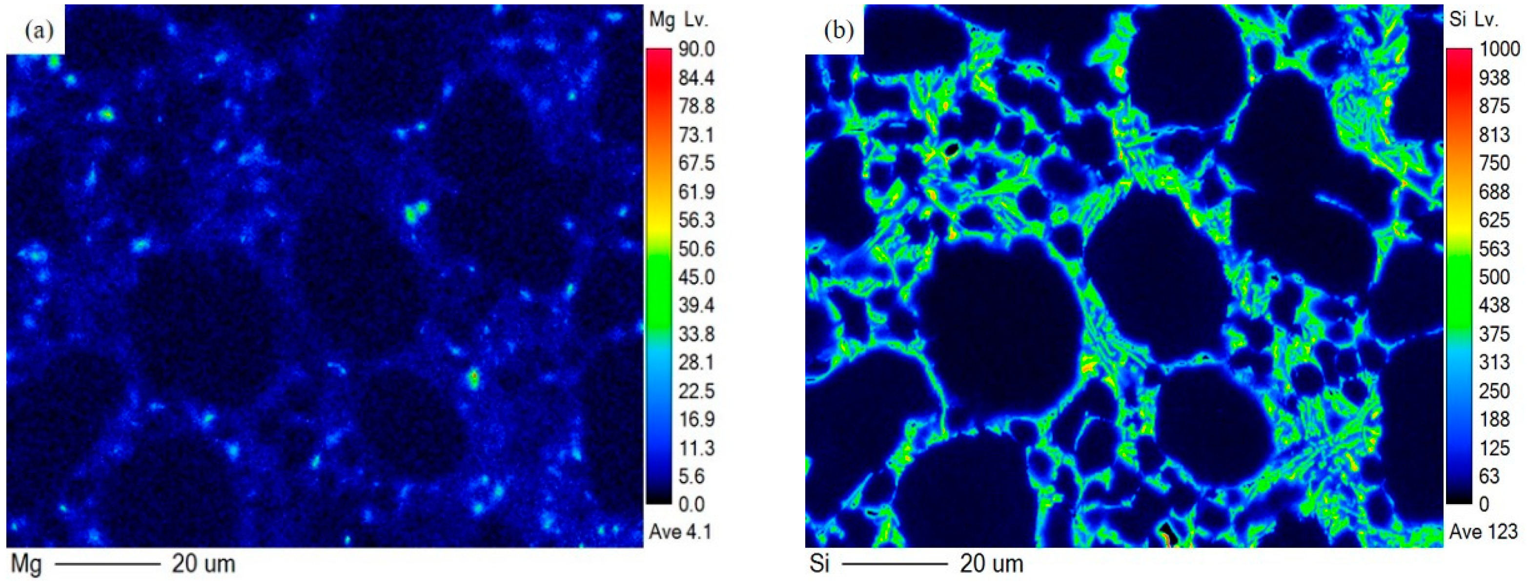
Figure 11 shows the element distribution of Al-7Si-0.5Mg aluminum alloy semi-solid die-casting test bars before and after heat treatment. It can be seen from the figure that Mg and Si atoms are mainly distributed between α-Al grains before heat treatment, but after heat treatment Mg is dissolved in the matrix. A small fraction of Si atoms enters α-Al, but most of them still exist in the form of discontinuous granular eutectic. There are some Mg-enriched microdomains in Figure 11a,c, which may be caused by the uneven distribution of elements caused by insufficient homogenization.

4. Discussion

4.1. Formation of Non-Dendritic α-Al Grains

According to previous studies on semi-solid slurry, the formation of spherical microstructure of semi-solid slurry includes dendrite arm fragmentation mechanism, dendrite arm root remelting mechanism and nucleation-controlled mechanism [28,29,30]. Kirkwood [31] believed that the agitation applied to the melt created velocity field in the melt, and the velocity gradient acting on the dendrites generated shear stress leading to the breakage of the dendrites. Li et al. [32] prepared Al-7Si-0.5Mg alloy semi-solid slurry by self-inoculation method and believed that solute atoms were enriched at the root of dendrites and caused the root to fuse during the process of grain growth. A broken dendrite arm would form a new grain. Fan et al. [33] believed that during the pulping process, ideal semi-solid slurry could be obtained by promoting effective nucleation and controlling spherical growth, which required uniform temperature and concentration fields, high shear rate and turbulent flow.
The most important spheroidization mechanism in GISS semi-solid process is the nucleation-controlled mechanism. Under the dual action of ceramic tube stirring and bubble stirring, the nuclei formed by argon supercooling and heterogeneous particles will be dispersed throughout the melt, resulting in spherulites. In addition, during the double stirring, the temperature and solute distribution in the melt are in a relatively uniform state, which is beneficial to the spherical growth of grains. However, there is no spherulites formation in the top area in contact with air, which is similar to conventional casting [10]. In addition, the uniform temperature distribution caused by stirring reduces the thermal motion between atoms, reduces structural fluctuations and enables a large number of crystal nuclei to be preserved, which is beneficial to the grains’ refinement. In traditional casting, the presence of temperature and concentration gradients at the solid–liquid interface causes dendrite growth due to its non-uniform temperature and solute distribution.

4.2. Influence of Holding Time on Semi-Solid Microstructure

After stirring for a period of time, broken dendrites generated in the initial stage of bubble stirring can be rounded [34], because holding promotes the uniform distribution of melt temperature. In order to reduce the surface energy, broken dendrites will spontaneously develop towards rose-like and spherical shape, as shown in Figure 6a. Nafisi et al. [35] found that in order to reduce the total energy of the system, particles with arbitrary morphology would tend to grow spherically to reduce the surface energy during the holding process. However, as holding time increased, the spherulites collided with each other, gathered and dispersed from time to time. If positional relationship between their contact positions was appropriate, they would eventually fuse together to form large ellipsoid and petal-shaped grains, as shown in Figure 6c,d. If holding time is too long, according to the Gibbs–Thomson law, solute concentration in the liquid phase around the large grains is high, and solute concentration in the liquid phase around the small grains is low, resulting in a concentration gradient. Al atoms diffuse from small grains to large grains, making the large grains larger and the small grains smaller until they melt, the process called Oswald ripening [36,37]. There is a large difference in solid fraction when comparing the results shown in Figure 4b calculated by DSC analysis and Figure 7 and Figure 9 which were measured by quantitative image analysis. The higher solid fraction measured by image analysis could be related to the solidification process. The whole solidification could be divided into two stages, isothermal shearing with continuous cooling or holding in the crucible and quenching. During isothermal shearing, heterogeneous nucleation occurs continuously and uniformly distributed throughout the entire volume of the melt. Because of intensive forced convection, the growth of the nuclei takes place in a spherical manner, resulting in the formation of spherical grains, with the conventional dendritic primary phase being eliminated. The secondary solidification starts when the semi-solid slurry leaves the GISS device for water quenching. At this stage, the remaining liquid still has largely uniform temperature and composition fields, due to the prior intensive shearing. With the large cooling rate during water quenching, nucleation is expected to take place throughout the entire remaining liquid with a high nucleation rate and the nuclei survive and grow. During quenching, a large number of nuclei formed in the remaining liquid compete against each other to grow and solidification finishes before the growth instability occurs, preventing the development of dendrites. Therefore, the solid fraction obtained by image analysis includes not only the primary solidified spherical grains, but also the ones formed during quenching, resulting in higher solid fraction. Deepak et al. [38] found that the growth of α-Al in the isothermal process conformed to the kinetic equation of D t 3 D 0 3 = K t (where Dt and D0 are the average grain size at times t and 0, and K is the constant of coarsening rate).

4.3. Effect of Medium Alloy Addition on Semi-Solid Microstructure

The Al-5Ti-B medium alloy is composed of three phases, α-Al, TiB2 and TiAl3. The nucleation rate increases by increasing the nucleation sites to achieve the purpose of grain refinement [39]. The addition of medium alloy increases the number and density of grains, which is beneficial to improve the mechanical properties of test bars. At present, the refinement mechanisms of Al-5Ti-B medium alloys include boride particle theory [40,41], peritectic theory [42] and double nucleation theory [43]. Among them, the double nucleation theory is relatively complete. This theory holds that Al-5Ti-B medium alloy is added to melt to release TiB2, TiAl3 and other particles. TiB2 has a high melting point and good stability and can be used as nucleation particles, while TiAl3 first dissolves and then precipitates on the surface of TiB2 to form a thin layer. The layer of TiAl3 reacts with the liquid phase to form α-Al to refine the grains [42,44]. Fan et al. [45] used high-resolution electron microscopy to find that TiAl3 existed between TiB2 and α-Al, and TiAl3 could significantly improve the nucleation ability of TiB2. It can be seen from Figure 8a–c that with the increase of medium alloy content, the average size of grains decreases continuously. However, excessive addition of medium alloy reduces the sphericity of microstructure and increases the average grain size, as shown in Figure 8d. The reason may be that excessive medium alloy tends to agglomerate the TiAl3 particles, which reduces the refining effect. Therefore, the addition of medium alloy should be appropriate.

4.4. Mechanical Properties of Traditional Die Casting and Semi-Solid Die-Casting

The difference in mechanical properties between traditional die-casting and semi-solid die-casting is mainly caused by the difference in their microstructure due to the different filling and solidification methods [2]. For traditional die-casting, high-temperature melt fills the cavity in a turbulent way, and turbulent filling is prone to air entrainment, resulting in defects such as pores and shrinkage holes in the solidified structure, as shown in Figure 10c. During semi-solid die-casting, slurry has high viscosity due to the existence of a certain solid phase, which is not easy to be entrained, and fills the cavity smoothly. The original fine grains or spherulites in the semi-solid slurry cool and grow in the mold. Semi-solid die-casting has fewer pores and smaller sizes, as shown in Figure 10d, which is one of the reasons why the mechanical properties of semi-solid test bars are higher than liquid test bars.
For semi-solid die-casting test bars, the eutectic silicon is refined due to the stirring effect during slurry process, the size is reduced and splitting effect on the matrix is reduced [35]. This is one of the reasons why mechanical properties of as-cast semi-solid die-casting bars are better than as-cast liquid die-casting bars. The spheroidization of eutectic silicon after heat treatment further reduces the splitting effect on the matrix and further improves the performance.
In addition, the dispersed and distributed strengthening phase Mg2Si produced after heat treatment is also an important factor for its performance improvement. During solid solution, Mg2Si melts into the matrix to form supersaturated solid solution, and then precipitates during natural aging and artificial aging stages [39,46]. In this paper, the distribution results of Mg and Si are obtained by EPMA test. It is found that Mg elements are uniformly distributed in the matrix after heat treatment, but it is not certain whether there is formation of Mg2Si. Because Mg in Al is around 1% at room temperature, however, Jiang et al. [39] used transmission electron microscopy to analyze the morphology and selected area electron diffraction of Al-7Si-0.5Mg aluminum alloy strengthening phase, and found that the size of the Mg2Si strengthening phase was about 5 nm, and the tensile strength of the test bar increased after heat treatment up to 38%.

5. Conclusions

1. While preparing Al-7Si-0.5Mg semi-solid slurry by GISS process, increasing a certain holding time is beneficial to the spheroidization of grains. However, with the increase of holding time, the sphericity decreases, and grains grow up. At 85 s, the average grain size and average shape factor of Al-7Si-0.5Mg aluminum alloy are ~95 μm and ~0.80, respectively.
2. With the increase of medium alloy addition, the average grain size of the primary phase decreases and the sphericity increases, but the addition of excess medium alloy increases the size of the primary phase and reduces the sphericity. When the amount of medium alloy was 1.5%, the average grain size and average shape factor are ~68 μm and ~0.83, respectively.
3. Compared with traditional liquid die-casting, the semi-solid die-casting aluminum alloy has higher mechanical properties. After heat treatment, the plate-like eutectic silicon is spheroidized and Mg2Si strengthening phase is dispersed and precipitated. The yield strength, tensile strength and elongation can reach ~240 MPa, ~307 MPa and ~8.8%, respectively.

Author Contributions

Conceptualization, G.G. and L.X.; methodology, G.G., R.L. and Y.L.; software, L.X.; validation, G.G., L.X. and R.P.; formal analysis, R.L., W.X. and R.P.; investigation, G.G., L.X., W.X. and Y.L.; resources, R.L., W.X., Y.L. and R.P.; data curation, G.G., L.X. and W.X.; writing—original draft preparation, G.G. and L.X.; writing—review and editing, G.G., L.X. and R.P.; visualization, G.G.; supervision, G.G.; project administration, G.G. and R.L.; funding acquisition, G.G. and Y.L. All authors have read and agreed to the published version of the manuscript.

Funding

Project (2021ZLGX01) and (2020CXGC010305) supported by the Key Research and Development Program of Shandong Province, China; Project (BK20160369) supported by the Natural Science Foundation of Jiangsu Province, China; Project (No. 51705292) supported by the National Natural Science Foundation of China (NSFC), China; and Project (ZR201702180340) supported by the Natural Science Foundation of Shandong Province, China.

Data Availability Statement

Not applicable.

Acknowledgments

We acknowledge SINOTRUK for the support of die-casting equipment provided for experiments. We would also like to acknowledge the technical support from Shandong University Testing and Manufacturing Center for Advanced Materials.

Conflicts of Interest

The authors declare no conflict of interest.

References

  1. Qi, M.F.; Kang, Y.L.; Zhou, B. A forced convection stirring process for Rheo-HPDC aluminum and magnesium alloys. J. Mater. Process. Technol. 2016, 234, 353–367. [Google Scholar] [CrossRef]
  2. Kang, Y.L.; Li, J.Y.; LI, G.N. Preparation and Rheological Die-Casting of 7075 Aluminum Alloy Semisolid Slurry. J. Netshape Form. Eng. 2020, 12, 74–80. [Google Scholar]
  3. Qi, M.F.; Kang, Y.L.; Zhu, G.M. Microstructure and properties of rheo-HPDC Al-8Si alloy prepared by air-cooled stirring rod process. T Nonferrous Metal. Soc. 2017, 27, 1939–1946. [Google Scholar] [CrossRef]
  4. Xue, L.W.; Zhou, W.Q.; Piao, Y.N. Progress in effects of squeeze casting process parameters and heat treatment on microstructure and properties of Al-Si alloy. Spec. Cast. Nonferrous Alloy. 2021, 41, 842–848. [Google Scholar]
  5. Zhou, B.; Qiu, Z.Y.; Chen, K.P.; Xu, C.; Wang, Z.Y. Microstructure, properties, and numerical simulation of semi-solid aluminum alloy under planetary stirring process. Materials 2022, 15, 3009. [Google Scholar] [CrossRef]
  6. Liao, F.J.; Wang, L.D.; Zhu, D.Y. Preparation of aluminum alloy semi-solid slurry by internal cooling process. Spec. Cast. Nonferrous Alloy. 2017, 37, 1208–1211. [Google Scholar]
  7. Zhu, Y.L.; Xu, X.L.; Zhao, J.W. Effect on microstructure and corrosion resistance of semi-solid slurry of 7A04 aluminum alloy by electromagnetic stirring. Mater. Res. Express. 2021, 8, 16506–16517. [Google Scholar] [CrossRef]
  8. Hong, X.; Liu, Z.; Zhang, K.W. Effects of current mutation on electromagnetic field and solidified microstructure in semi-solid A356 aluminum alloy under electromagnetic. Spec. Cast. Nonferrous Alloys 2021, 41, 1393–1399. [Google Scholar]
  9. Shabestari, S.G.; Honarmand, M.; Saghafian, H. Microstructural evolution of A380 aluminum alloy produced by gas-induced semi-solid technique (GISS). Adv. Mater. Processing Technol. 2015, 1, 155–163. [Google Scholar] [CrossRef]
  10. Wannasin, J.; Martinez, R.; Flemings, M. Grain refinement of an aluminum alloy by introducing gas bubbles during solidification. Scr. Mater. 2006, 55, 115–118. [Google Scholar] [CrossRef]
  11. Li, M.; Yang, W.L.; Zhang, Y. Microstructure and mechanical properties of AZ91D magnesium alloy rheo-diecasting prepared by self-inoculation method. Trans. Mater. Heat Treat. 2020, 41, 41–48. [Google Scholar]
  12. Jain, A.; Ratke, L.; Sharma, A. Non-dendritic structural changes in Al-7Si alloy cast through rapid slurry formation (RSF) process. Trans. Indian Inst. Met. 2012, 65, 545–551. [Google Scholar] [CrossRef]
  13. Granath, O.; Wessén, M.; Cao, H. Determining effect of slurry process parameters on semi-solid A356 alloy microstructures produced by RheoMetal process. Int. J. Cast Met. Res. 2013, 21, 349–356. [Google Scholar] [CrossRef]
  14. Das, P.; Samanta, S.K.; Das, R. Optimization of degree of sphericity of primary phase during cooling slope casting of A356 Al alloy: Taguchi method and regression analysis. Measurement 2014, 55, 605–615. [Google Scholar] [CrossRef]
  15. Geng, X.X.; Mao, W.M.; Li, N.Y. Effect of serpentine channel preparation method on semi-solid slurry of 6061 aluminum alloy. Spec. Cast. Nonferrous Alloys 2021, 41, 900–904. [Google Scholar]
  16. Wang, M.; Liu, X.B.; Guo, H.M. Preparation of semi-solid slurries of A356 alloy by helical curve duct. Spec. Cast. Nonferrous Alloys 2015, 35, 941–944. [Google Scholar]
  17. Li, G.; Qu, W.Y.; Luo, M. Semi-solid processing of aluminum and magnesium alloys: Status, opportunity, and challenge in China. T Nonferrous Metal. Soc. 2021, 31, 3255–3280. [Google Scholar] [CrossRef]
  18. Luo, S.J.; Keung, W.C.; Kang, Y.L. Theory and application research development of semi-solid forming in China. T Nonferrous Metal. Soc. 2010, 20, 1805–1814. [Google Scholar] [CrossRef]
  19. Gao, J.; Chen, Y.L.; Wang, L.D.; Li, Q.J. Study on Preparation of semi-solid aluminum-silicon alloy slurries. Hot Work. Technol. 2013, 42, 14–17. [Google Scholar]
  20. Li, J.Q.; Zhang, L.; Dong, X.P. Study on Microstructure of Semi-Solid Magnesium Alloy Manufactured by Gas Bubbles Stirring. Adv. Mater. Res. 2010, 129–131, 728–732. [Google Scholar] [CrossRef]
  21. Honarmand, M.; Salehi, M.; Shabestari, S.G. Impact strength and structural refinement of A380 aluminum alloy produced through gas-induced semi-solid process and Sr addition. T Nonferrous Metal. Soc. 2022, 32, 1405–1415. [Google Scholar] [CrossRef]
  22. Zou, Y.; Dong, X.P.; Zhang, J.; Fan, Z.T.; Wang, A.H. A new casting technique of agitating semi-solid magnesium alloy using a gas blowing method. Foundry 2008, 57, 215–218. [Google Scholar]
  23. He, F.; Zhuang, L.Z.; He, G.Y. A356 aluminum alloy for automobile wheel hubs-research process and influence of alloying elements on its microstructure and properties. Foundry 2021, 70, 431–437. [Google Scholar]
  24. Li, J.J.; Zhang, X.T. Optimization of different pressure casting process of automobile bracket. Hot Work. Technol. 2021, 50, 71–74. [Google Scholar]
  25. Wang, Z.L.; Zhu, X.B.; Wang, G.Y. Analysis and countermeasure of pinhole defects in A356 cylinder head casting. Anhui Polytech. Univ. 2019, 34, 38–43. [Google Scholar]
  26. Ran, G.; Zhou, J.E.; Wang, Y.F. Microstructure and tensile properties of cast A356 aluminum alloy. Heat Treat. Met. 2007, 32, 13–18. [Google Scholar]
  27. Zabler, S.; Rueda, A.; Rack, A.; Riesemeier, H.; Zaslansky, P.; Manke, I.; Garcia-Moreno, F.; Banhart, J. Coarsening of grain-refined semi-solid Al-Ge32 alloy:X-ray microtomography and in situ radiography. Acta Mater. 2007, 55, 5045–5055. [Google Scholar] [CrossRef]
  28. Dong, J.; Lu, G.M.; Ren, X.F. Discussion on the formation mechanism of nondendritic semi-solid microstructures during liquidus casting. Acta Metall. Sin. 2002, 38, 203–207. [Google Scholar]
  29. Ji, S.; Fan, Z.; Bevis, M.J. Semi-solid processing of engineering alloys by a twin-screw rheomoulding process. Mater. Sci. Eng. A 2001, 299, 210–217. [Google Scholar] [CrossRef]
  30. Pilling, J.; Hellawell, A. Mechanical deformation of dendrites by fluid flow. Metall. Mater. Trans. A 1996, 27, 229–232. [Google Scholar] [CrossRef]
  31. Kirkwood, D.H. Semisolid metal processing. Int. Mater. 2013, 39, 174–189. [Google Scholar] [CrossRef]
  32. Li, M.; Li, Y.D. Microstructural evolution of A356 aluminum alloy during continuous cooling, isothermal holding and furnace cooling. Trans. Mater. Heat Treat. 2020, 41, 23–31. [Google Scholar]
  33. Fan, Z.; Ji, S.; Liu, G.J. Development of the rheo-diecasting process for Mg-alloys. Mater. Sci. Forum 2005, 488–489, 405–412. [Google Scholar] [CrossRef]
  34. Zhang, L.; Dong, X.P.; Li, J.Q. Microstructure evolution of Al-Si semi-solid slurry by gas bubble stirring method. J. Cent. South Univ. 2011, 18, 1789–1794. [Google Scholar] [CrossRef]
  35. Nafisi, S.; Ghomashchi, R. Effect of stirring on solidification pattern and alloy distribution during semi-solid-metal casting. Mater. Sci. Eng. A 2006, 437, 388–395. [Google Scholar] [CrossRef]
  36. Voorhees, P.W.; Glicksman, M.E. Ostwald ripening during liquid phase sintering—Effect of volume fraction on coarsening kinetics. Metall. Mater. Trans. A 1984, 15, 1081–1088. [Google Scholar] [CrossRef]
  37. Li, M.; Li, Y.D.; Bi, G.L. Effects of melt treatment temperature and isothermal holding parameter on water-quenched microstructures of A356 aluminum alloy semisolid slurry. T Nonferrous Metal. Soc. 2018, 28, 393–403. [Google Scholar] [CrossRef]
  38. Deepak, K.S.; Mihira, A.; Mandai, A.; Chakraborty, M. Coarsening kinetics of semi-solid A356–5 wt% TiB2in situ composite. T rans. Nonferrous Metal. Soc. India 2015, 6, 1075–1080. [Google Scholar]
  39. Jiang, J.F.; Wang, Y.; Xiai, G.F. Influence of modification, refinement and heat treatment on mechanical properties of A356 Al-alloy components prepared by squeeze casting. J. Mater. Res. 2020, 34, 881–891. [Google Scholar]
  40. Guzowski, M.M.; Sigworth, G.K.; Sentner, D.A. The role of boron in the grain. Metall. Mater. Trans. A 1987, 5, 603–619. [Google Scholar] [CrossRef]
  41. Murty, B.S.; Kori, S.A.; Chakraborty, M. Grain refinement of aluminum and its alloys by heterogeneous nucleation and alloying. Int. Mater. Rev. 2013, 47, 3–29. [Google Scholar] [CrossRef]
  42. Chen, Y.J.; Xu, Q.Y.; Huang, T.Y. Development of research on grain refiners for aluminum alloys. Mater. Rep. 2006, 20, 57–61. [Google Scholar]
  43. Mohanty, P.S.; Samuel, F.H.; Gruzleski, J.E. Studies on addition of inclusions to molten aluminum using a novel technique. Metall. Mater. Trans. B 1995, 26, 103–109. [Google Scholar] [CrossRef]
  44. Schumacher, P.; Greer, A.L.; Worth, J. New studies of nucleation mechanisms in aluminum alloys: Implications for grain refinement practice. J. Mater. Sci. Technol. 1998, 14, 394–404. [Google Scholar] [CrossRef]
  45. Fan, Z.; Wang, Y.; Zhang, Y. Grain refining mechanism in the Al/Al-Ti-B system. Acta Mater. 2015, 84, 292–304. [Google Scholar] [CrossRef]
  46. Cheng, L.; Lu, H.X.; Zhu, Q. Evolution of microstructure and mechanical properties of semi-solid squeeze cast A356.2 aluminum alloy during heat treatment. Solid State Phenom. 2019, 285, 139–145. [Google Scholar] [CrossRef]
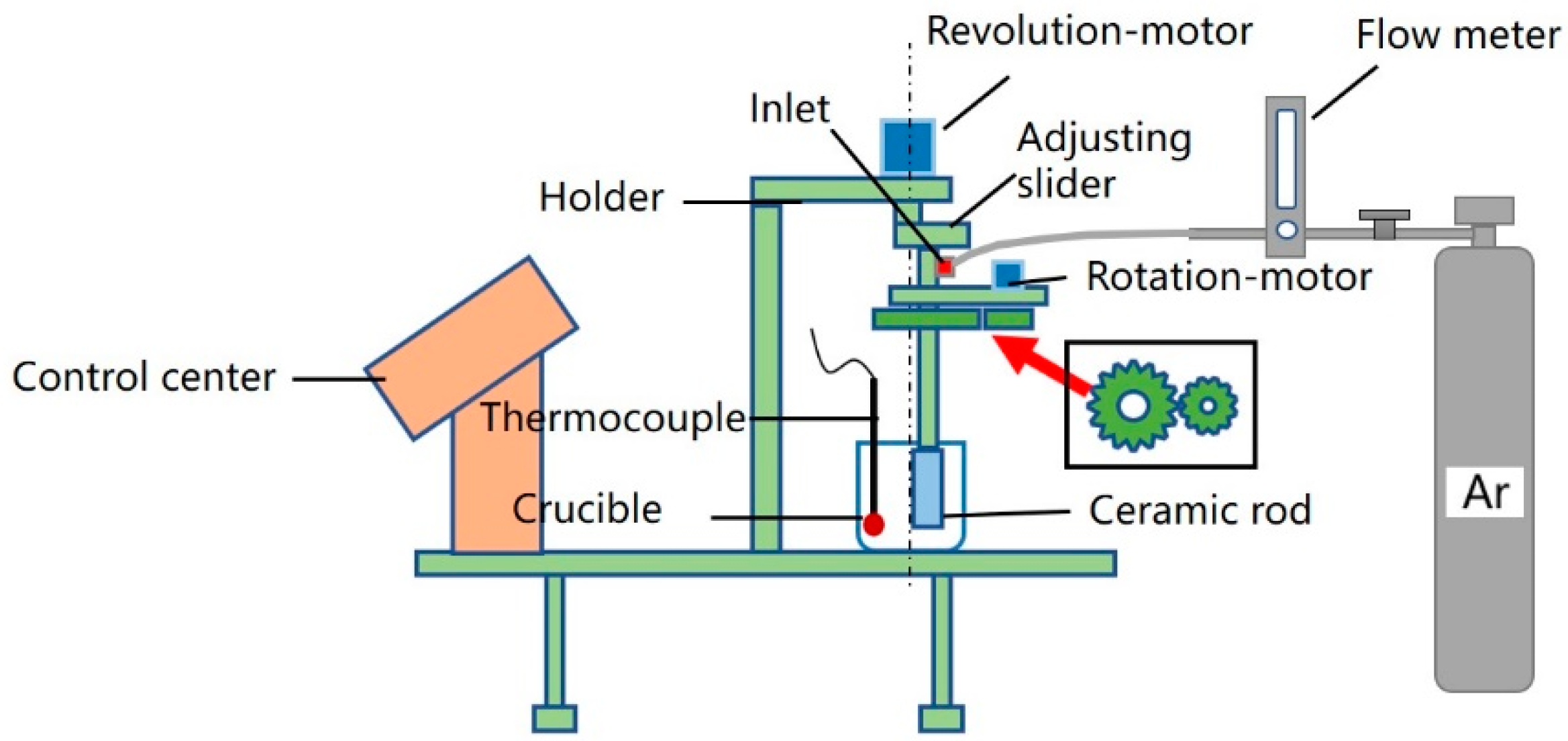
Figure 1. Schematic diagram of GISS.
Metals 12 01600 g001
Figure 2. Segmentation of optical micrographs using a thresholding-based histogram algorithm. (a) Optical micrograph showing brighter solid grains and darker liquid phase; (b) binary image where black areas correspond to liquid phase; (c) grain boundaries identification by watershed segmentation method.
Metals 12 01600 g002
Figure 3. Al-7Si-0.5Mg aluminum alloy sample dimensions (unit: mm).
Metals 12 01600 g003
Figure 4. The result of (a) heat flow vs. temperature at heating and cooling rates of 20 °C/min and (b) solid fraction vs. temperature analyzed by DSC tests.
Metals 12 01600 g004
Figure 5. Temperature curve of semi-solid slurry during holding.
Metals 12 01600 g005
Figure 6. Microstructure of semi-solid slurry for different holding time. (a) 85 s—605 °C; (b) 160 s—600 °C; (c) 220 s—595 °C; (d) 270 s—590 °C.
Metals 12 01600 g006aMetals 12 01600 g006b
Figure 7. Effects of different holding time on the solid fraction and microstructure of semi-solid slurry.
Metals 12 01600 g007
Figure 8. Microstructure of semi-solid slurry for different medium alloy additions. (a) 0.5 wt%—605 °C; (b) 1.0 wt%—605 °C; (c) 1.5 wt%—605 °C; (d) 2.0 wt%—605 °C.
Metals 12 01600 g008
Figure 9. Effect of medium alloy addition on solid fraction and microstructure of semi-solid slurry.
Metals 12 01600 g009
Figure 10. Fracture of tensile specimen of Al-7Si-0.5Mg aluminum alloy. (a) as-cast test bar of liquid die-casting; (b) as-cast test bar of semi-solid die-casting; (c) T6 test bar of liquid die-casting; (d) T6 test bar of semi-solid die-casting.
Metals 12 01600 g010
Figure 11. Element distribution of Al-7Si-0.5Mg test bar. (a) Mg in as-cast; (b) Si in as-cast; (c) Mg in T6; (d) Si in T6.
Metals 12 01600 g011aMetals 12 01600 g011b
Table 1. Chemical composition of Al-7Si-0.5Mg aluminum alloy (wt%).
SiCuMgMnFeTiAl
6.840.02610.4920.00860.02710.037192.5
Table 2. The process parameters of GISS.
Process ParametersVaried ValueFixed ValueRemark
Holding time/s85
160
220
270
Ventilation temperature 625 °C, revolution 90 r/min, rotation 150 r/min, ventilation time 4 min, flow 0.35 m3/h, water coolingMedium alloy addition 1.0 wt%,
Medium alloy addition/wt%0.5
1.0
1.5
2.0
Holding time 85 s
Table 3. Mechanical properties of traditional liquid die-casting and semi-solid die-casting.
Forming ProcessStateYield Strength/MPaTensile Strength/MPaElongation/%
liquid die-castingas-cast129 ± 6242 ± 811.2 ± 0.1
semi-solid die-casting136 ± 5266 ± 811.6 ± 0.2
liquid die-castingT6210 ± 7238 ± 71.6 ± 0.3
semi-solid die-casting240 ± 6307 ± 78.8 ± 0.2
Publisher’s Note: MDPI stays neutral with regard to jurisdictional claims in published maps and institutional affiliations.