Article

Process Modelling Applied to Aluminium-Steel Butt Welding by Hybrid Metal Extrusion and Bonding (HYB)

1
Department of Mechanical and Industrial Engineering, Norwegian University of Science and Technology, Richard Birkelands vei 2b, 7491 Trondheim, Norway
2
HyBond AS, NAPIC Richard Birkelands vei 2b, 7491 Trondheim, Norway
3
Department of Computational Materials Processing, Institute for Energy Technology, 2027 Kjeller, Norway
4
Department of Management and Engineering, University of Padova, Stradella S. Nicola 2, I-36100 Vicenza, Italy
*
Author to whom correspondence should be addressed.
Metals 2022, 12(10), 1656; https://doi.org/10.3390/met12101656
Submission received: 27 August 2022 / Revised: 27 September 2022 / Accepted: 28 September 2022 / Published: 30 September 2022
(This article belongs to the Special Issue Advances in Dissimilar Welding and Joining)

Abstract

:
In the present investigation, the numerical code WELDSIM is used to simulate butt welding of 4 mm thick plates of S355 steel and AA6082-T6 by Hybrid Metal Extrusion and Bonding (HYB). This is a new solid state joining process using continuous extrusion as a technique to enable aluminium filler metal additions. In WELDSIM, the finite element heat flow model is coupled to a frictional heating model, an isokinetic diffusion model for the interfacial intermetallic compound (IMC) formation and a nanostructure model for simulating reversion and re-precipitation of hardening phases inside the aluminium part of the joints during welding and subsequent natural ageing. The HYB process model is validated by comparison with experimental data obtained from in-situ thermocouple measurements and hardness testing carried out on three different Al-steel butt welds. Furthermore, scanning electron microscope examinations of the Al-steel interfaces have been conducted to check the predicted power of the IMC diffusion model. It is concluded that the process model is sufficiently relevant and comprehensive to be used in simulations of both the thermal, microstructure, and strength evolutions fields in these dissimilar butt welds. Some practical applications of the process model are described toward the end of the article, where particularly its potential for optimising the load-bearing capacity of the joints, is highlighted.

1. Introduction

In welding of dissimilar metals, such as aluminium to steel, bonding occurs by intermetallic compound (IMC) formation [1]. Because IMCs, in general, are known to be both hard and brittle, this makes joining particularly challenging to prevent interfacial cracking from occurring during subsequent tensile loading [2]. Normally, fusion welds will be most prone to such cracking, since the inherent melting of the aluminium base and filler metals leads to the formation of a continuous IMC layer along the entire joint line, where the layer thickness typically varies from 5 to 20 μm [3]. At the same time, the high heat inputs normally associated with conventional fusion welding result in the build-up of large thermal stresses upon cooling of the welds down to room temperature (RT) due to the pertinent difference in the thermal expansion coefficients between aluminium and steel [4]. This, in turn, leads to crack formation in the IMC layer along the Al-steel interface and sometimes also to failure even before the as-welded component has been subjected to external loading [2].
The use of a solid-state joining technique like friction stir welding (FSW) reduces many of the problems associated with fusion welding of Al-steel components by virtue of its low process temperature, which restricts the growth of the IMC layer along the Al-steel interface [5]. Furthermore, since FSW involves no melting of the parent materials it is also possible to design a special tool pin that partially will machine or scribe the steel interface so that additional bonding occurs by mechanical interlocking [5]. Nevertheless, because the mechanical properties achieved are difficult to control in a real welding situation, welded Al-steel components have, in spite of their obvious weight reduction potential, not yet found a wide industrial application. As a matter of fact, only a few examples exist in the scientific literature on the practical use of such components in load-bearing structures [6]. These include FSW of die-cast members in hybrid aluminium-steel frameworks [7], friction welding of galvanized steel studs to aluminium inner-trunk panels [8] and overlap FSW of aluminium-steel members in front car subframes [9].
Recently, a new solid state joining method has been developed, known as the Hybrid Metal Extrusion and Bonding (HYB) process, which utilizes continuous extrusion as a technique to enable aluminium filler metal (Al-FM) additions [10]. Originally, the idea was to use HYB for butt welding of aluminium plates and profiles, but over the years the method has evolved into a multi-material joining technique being particularly suitable for Al-steel welding [11,12]. This is mainly because of its low process temperature along with the use of smart tool design, which allows bonding to occur by a combination of microscale mechanical interlocking and IMC formation, where the IMC layer is in the sub-micrometre range (<1 µm) [13,14]. Moreover, the subsequent benchmarking of HYB against gas tungsten arc welding, pulsed and conventional gas metal arc welding (GMAW), laser beam welding (LBW), cold metal transfer welding (CMTW), and FSW shows that both the ultimate tensile strength and the fatigue properties of the third generation Al-steel HYB butt weld surpass those reported for similar Al-steel welds produced by the other methods [14,15]. At the same time, the HYB process allows butt welding to be performed at much higher travel speeds compared to FSW, without compromising the mechanical integrity of the weldment. This shows that HYB exhibits an inherent advantage in multi-material joining along with an unreleased potential for further process optimisation compared to its competitors [11,16].
So far, the aptness of the HYB process for Al-steel butt welding has been demonstrated through in-depth microstructure characterisation and extensive tensile and fatigue testing [13,14,15], but no modelling of the underlying thermal and microstructural fields controlling the resulting joint properties has been conducted. Therefore, the timing is perfect for taking the HYB process technology to the next level by developing a verified quantitative understanding of the different physical phenomena involved contributing to its unique multi-material joining capabilities. This will be done by taking full advantage of the previous modelling work mainly done on FSW of corresponding monometallic Al-Al butt welds [17,18,19] and condense all that accumulated knowledge into a finite element (FE)-based simulation model for HYB Al-steel butt welding. The HYB process model, which is built around the numerical code WELDSIM [20,21], will then be validated by comparison with in-situ thermocouple measurements and experimental hardness profiles. Subsequently, the graphical visualisation capabilities of WELDSIM will be explored to disclose the asymmetrical thermal field across the joint interface as well as the strength evolution on the aluminium side of the joint, both in the as-welded condition and following complete ageing (NA) at room temperature (RT). In addition, a separate module for predicting the IMC layer thickness at the Al-steel interface under varying welding conditions has been implemented as a sub-routine in the FE code, based on the isokinetic diffusion model previously developed by two of the authors [12].

2. Components of Process Model

The symbols and abbreviations used throughout this chapter are defined in the Appendix A. The corresponding units are provided in brackets in the symbol list.
In the following, a summary of the HYB process model will be given, starting with a brief outline of the HYB process and how a butt-welding operation is conducted in the Al-steel case. This information is required to provide the reader with the necessary background and context for the modelling work.

2.1. The HYB PinPoint Extruder

Figure 1 shows a schematic drawing of a possible experimental set-up during Al-steel butt welding. Included is also a sketch of the HYB PinPoint extruder with its main tool parts. The extruder is built around a 10 mm diameter rotating pin provided with a set of moving dies through which the aluminium is allowed to flow. When the pin being attached to the drive spindle is rotating at a constant speed, the inner extrusion chamber with its three moving walls will drag the aluminium filler wire (Al-FW) both into and through the extruder due to the imposed friction grip. At the same time, it is kept in place inside the chamber by the stationary housing constituting the fourth wall.
Prior to the butt welding operation, the two base plates are first mounted in a fixture with a fixed spacing k , which in the flowing is referred to as the groove width. The plates rest again on a steel backing. During welding the HYB PinPoint extruder slides along the joint line at a constant travel speed v . At the same time, the rotating pin tip with its moving dies is submerged into the groove between the plates to be joined. Because the moving dies extend into the groove, the aluminium will start to flow through them as soon as the filler wire (FW) hits the abutment and the pressure build-up in front of it becomes sufficiently large to initiate extrusion [22]. Note that in the Al-steel butt welding case the pin tip is only supposed to touch the steel base metal (S-BM) groove wall without actually machining it. In contrast, the aluminium base metal (Al-BM) on the retreating side (RS) of the joint will be dragged along with the rotating pin and deposited in the groove behind, where bonding with the filler metal (FM) occurs inside the extrusion zone (EZ). By proper pre-setting of the two main process parameters controlling the FM deposition rate (i.e., the FW diameter and the drive spindle rotational speed N s ), a groove cross sectional area up to 30 mm2 can be filled in one pass using the current version of the HYB PinPoint extruder and a sensible value for the travel speed (i.e., in the range between 6 and 18 mm/s).
Further background information on the HYB PinPoint extruder, its main tool parts and the essential HYB process parameters can be found elsewhere [11,16].

2.2. Heat Generation Model

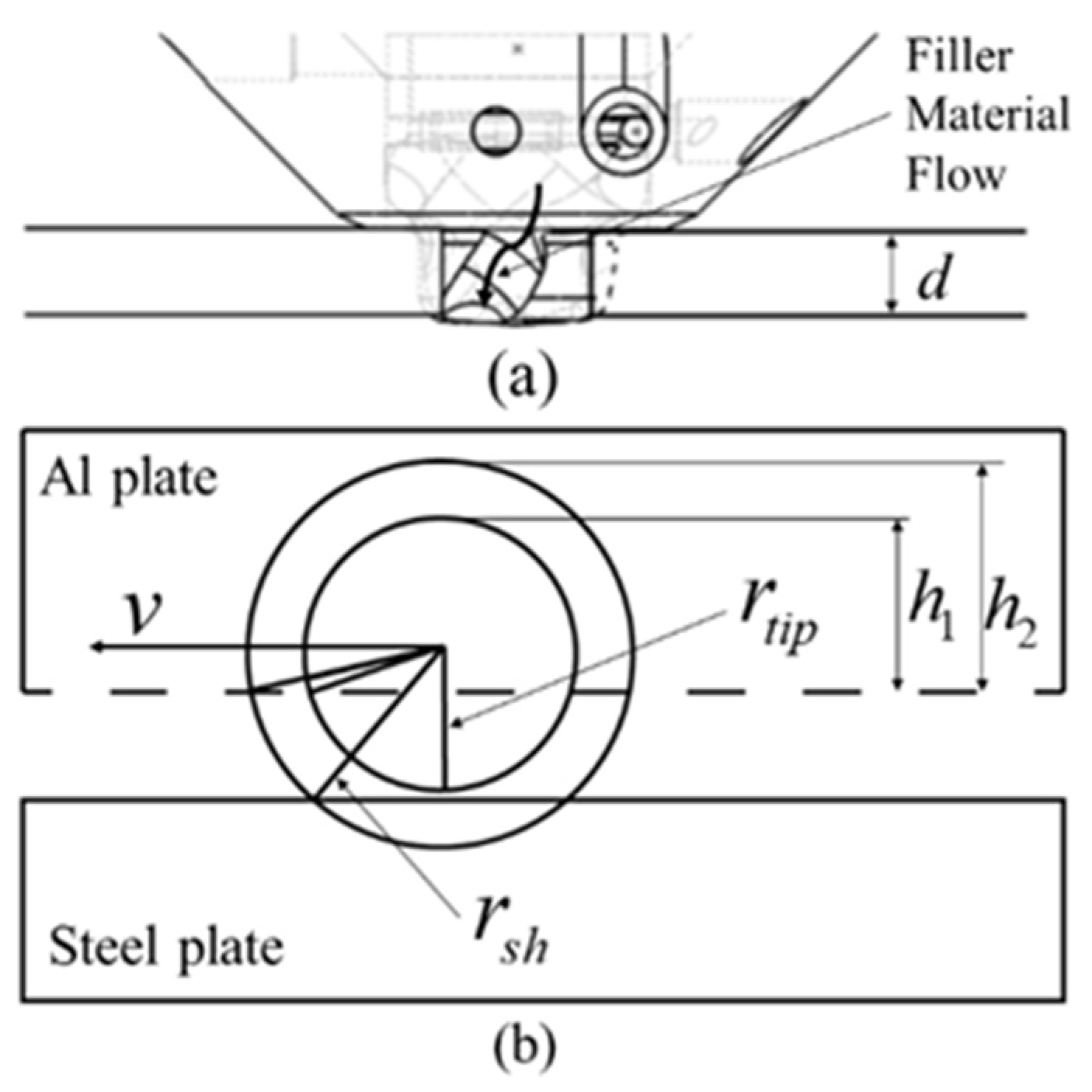
As a starting point, the semi-analytical frictional heating model previously developed by the authors for HYB Al-Al butt welding is invoked, covering the symmetrical case where the submerged pin tip is placed in the centre of the groove [23]. However, because the submerged pin tip in the present experimental set-up is only supposed to touch the steel groove wall during the welding operation, it needs to be slightly modified to also handle the asymmetrical case shown in Figure 2.
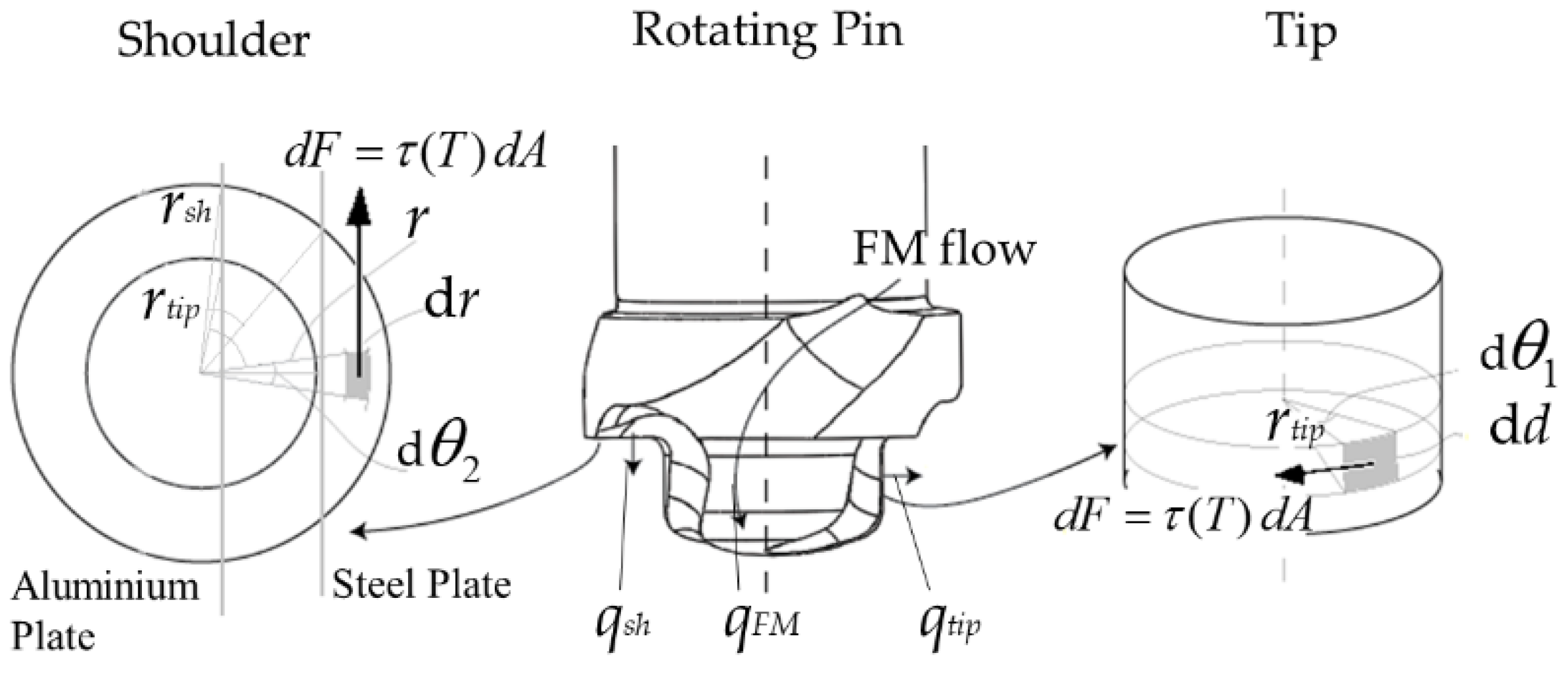
Still, both problems can be treated using the same mathematical framework, in which the net power input q 0 (in W) is written as the sum of three individual contributions [23]:
q 0 = q t i p + q s h + q F M
where q t i p , q s h and q F M refer to the individual contributions from the tip, the shoulder and the FM, respectively, as defined in Figure 3.
Note that the pin design outlined in Figure 3 is tailor-made for butt welding of plates being separated from each other by an I-groove, as shown previously in Figure 1. Further details about the HYB pin design and how the pin geometry can be customised to handle a wide range of different applications, ranging from butt, lap, slot, fillet and multi-pass welding to plate surfacing and additive manufacturing have been reported elsewhere [11].
The mathematical treatment eventually leads to the following general expression for q 0 [23]:
q 0 = f ( ω , τ , T int , v , r t i p , r s h , d , h 1 , h 2 , d m / d t , T F M )
where ω is the angular velocity of the tool, τ is the shear stress at the tool-matrix interface, T int is the temperature at the tool-matrix interface, v is the welding speed, r t i p is the radius of the tip of the tool, r s h is the radius of the shoulder of the tool, d is the thickness of the plates, h 1 is the difference between the radius of the tip and the half width of the groove, h 2 is the difference between the radius of the shoulder and the half width of the groove, d m / d t is the mass flow rate of hot FM passing through the extruder and T F M is the temperature of the hot extrudate entering the groove.
The frictional heating model is, in turn, coupled, via the Matlab iterative solution algorithm previously developed by the authors, to the external heat flow model, which calculates how the generated heat dissipates throughout the underlying base plates during welding [23]. By allowing Matlab first to interact with a simplified analytical heat flow model a sensible starting value for q 0 can quickly be obtained, based on a comparison between measured and predicted thermal cycles at the positions where the in-situ thermocouple measurements are conducted [23]. Then Matlab exports this input value to the FE heat flow model, which re-calculates the thermal field for exactly the same positions inside the heat-affected zone (HAZ). Matlab uses the outcome of this pre-calculation to automatically generate the next input value for q o to be employed in the subsequent heat flow simulation, and the whole process is repeated until a good agreement between predictions and measurements is obtained. Usually, convergent is achieved after a few iterations, provided that the starting value used in the subsequent fine-tuning process of q 0 is reasonably correct [24].

2.3. Combined HAZ Microstructure and Strength Evolution Model

In the HYB case the peak temperature within the EZ is typically between 400 °C and 500 °C [11], which is far below the Ac1 temperature of the S-BM where microstructural changes due to phase transformations occur. This has also been verified experimentally, confirming that the steel plate on the AS of the Al-steel HYB joint is only subjected to local work hardening close to the Al-steel interface due to interactions with the rotating pin and does not undergo any phase transformation [13,14]. On the other hand, the age hardened aluminium plate on the RS experiences severe softening due to the frictional heating occurring during the welding operation. Hence, an Al-steel HYB butt joint behaves more like a monometallic Al-Al butt weld in the sense that the global mechanical properties, in practice, are determined by the local HAZ properties on the aluminium side of the joint [13,14]. This makes modelling of the HAZ microstructure and strength evolution, based on nanostructure model (NaMo) simulations of the softening behaviour of Al-Mg-Si alloys, equally applicable for Al-steel HYB butt welds as it is for monometallic aluminium weldments [20,21,24].
Details of the underlying assumptions along with a full description of the constituent equations and basic features of NaMo can be found in well-established sources [25,26,27,28]. In brief, the version of NaMo that is integrated in the numerical code WELDSIM is composed of a precipitation model and a yield strength model that are coupled. The precipitation model consists of the following components:
  • A nucleation law, which predicts the number of stable nuclei that form at each time-step.
  • A rate law, which calculates either the dissolution or the growth rate of each discrete particle size class.
  • A continuity equation, which keeps record of the amount of solute being tied up as precipitates.
The yield strength model converts the relevant output parameters from the precipitation model into an equivalent RT yield stress through dislocation mechanics by considering the following contributions:
  • Precipitation hardening due to shearing and bypassing of particles σ p
  • Solid solution hardening effects σ s s which include the four major strengthening elements Si, Mg, Mn and Cu.
In Al-Mg-Si alloys, where several strengthening mechanisms are operative at RT, the individual strength contributions can be added linearly. Thus, taking σ i equal to the intrinsic yield stress of pure aluminium, the resulting expression for the yield strength σ y becomes:
σ y = σ i + σ s s + σ p
The conversion between yield strength and Vickers hardness H V is then done through the following well-established empirical relationship [28,29,30]:
σ y = 3.0 H V 48.1
In the most recent version of NaMo (known as NaMo-Version 2) also the RT storage and the cold deformation stages have been incorporated, which allows simulation of a full industrial assembly line for welded Al-Mg-Si components [29].

2.4. Isokinetic Diffusion Model Capturing the IMC Formation

Because bonding in Al-steel welds occurs via IMC formation, the reaction layer thickness X is a key parameter influencing the bond strength [31]. To enable prediction of the layer thickness in a real welding situation, a simple diffusion model has previously been developed by two of the authors [12]. The model, which is also implemented in the numerical code WELDSIM, is isokinetic in nature and allows X to be calculated via the Scheil integral from knowledge of the weld thermal cycle through the following equation:
X = X r 0 t d t t
where X r is a chosen reference value for the reaction layer thickness and t is the time constant for the diffusion-controlled reaction, in which all relevant activation energies and kinetic constants are embedded. Further details about the model and how it is constructed are provided elsewhere [12].

2.5. Numerical Heat Flow Model

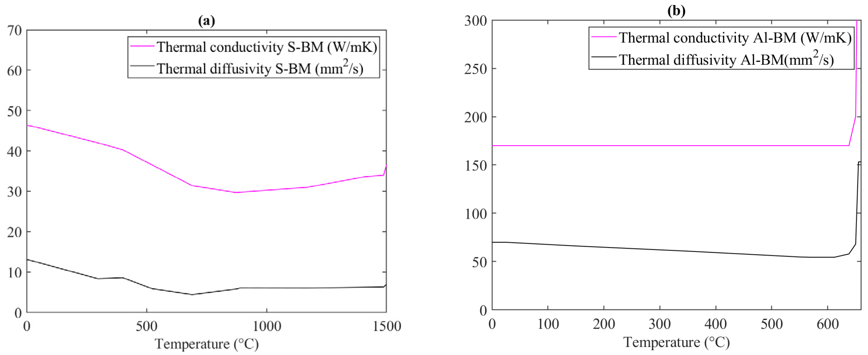
In WELDSIM, Patran 2019 is used for the mesh generation and the domains definition [32]. The mesh employed in the FE heat flow simulations of the Al-steel HYB butt welding operation is shown in Figure 4. Moreover, the two BMs have been assigned to their usual thermal properties, as shown by the data presented in Figure 5 [30,33]. In total, 47032 hexahedral finite elements are utilised to model the aluminium and steel base plates, whereas the underlying steel backing is made up of 17,000 hexahedral finite elements. Close to the joint line, a finer mesh is employed to allow for the steep thermal gradients within the EZ and the HAZ. Moreover, to account for the FM additions in the HYB case, new elements are continuously activated in the groove behind the rotating pin as the PinPoint extruder travels along the joint line.
In the FE heat flow simulations, the boundary conditions are represented by heat transfer coefficients between the base plates and their environments. The top and lateral surfaces of the aluminium and steel plates, which are exposed to air, are assumed to have equal convective heat transfer coefficients, both being assigned a value of 20 W/m2 °C [34]. This value is typical for natural convection. Similarly, the heat transfer coefficient between the two base plates and the underlying steel backing is fixed to 450 W/m2 °C, reflecting the rigid clamping conditions being employed in the HYB butt welding case.
In WELDSIM the calculated net power input q 0 is represented by a double ellipsoid volume distributed heat source [35], which is placed in the middle of the two adjoining base plates to simulate how the heat generation associated with friction and extrusion affects the resulting thermal fields. Note that the use of a distributed heat source ensures that the model also yields realistic values for the peak temperature inside the EZ following calibration against in-situ thermocouple measurements performed in the adjacent HAZ. Because a thermocouple being located too close to the weld centreline will inevitably be destroyed during the welding operation due to the rotating action of the pin, this is the only way the EZ temperature can be estimated.
Based on the calculated thermal fields, both the microstructure and strength evolution on the aluminium side of the joint can be simulated and the resulting IMC layer thickness along the Al-steel interface predicted, using the GLView Inova software for graphical visualization of the results [36].

3. Experimental Program

The experimental validation of the HYB Al-steel process model is done on the basis of special designed welding trials carried out using the pilot HYB machine (HYBond AS, Trondheim, Norwa) at the Norwegian University of Science and Technology (NTNU). This machine allows welds to be produced under controlled conditions, with full documentation of all relevant process parameters, e.g., temperature, torque, rotational speed, travel speed and wire feed rate as well as the main reaction forces acting on the extruder during welding. Further details about the HYB pilot machine and how it works can be found elsewhere [11,23].

3.1. Base Materials

In the butt welding trials, rolled plates of aluminium alloy 6082-T6 and rolled plates of structural steel S355 were used as base metals (BMs), both having an initial thickness of 4 mm. The other dimensions of the rolled plates were 500 mm × 100 mm. The aluminium filler wire (Al-FW) used was of the AA6082-T4 type produced by HyBond AS. The wire was made from a direct chill cast billet, which then was homogenized, hot extruded, shaved and cold drawn down to the final dimension of Ø1.4 mm. The chemical composition of the two BMs and the Al-FW can be found in Table 1 and Table 2, whereas Table 3 contains information about their RT mechanical properties.

3.2. Welding Conditions

In the present Al-steel HYB welding trials the extruder travel speed and the I-groove width k are the primary process variables. When the drive spindle rotational speed N s (and thus the FM deposition rate) is kept constant, full groove filling can be achieved at different travel speeds by only varying k . This follows from simple mass balance calculations [16]. Table 4 summarises the welding conditions employed in the three different HYB butt welding trials, which in the following are referred to as Series I, II and III, respectively.
The whole welding operation, as conducted using the HYB pilot welding machine at NTNU Aluminium Product Innovation Center (NAPIC), can be viewed at the following website: https://youtu.be/s1gzmN0I_Vs (accessed on 27 September 2022).

3.3. In-Situ Thermocouple Measurements

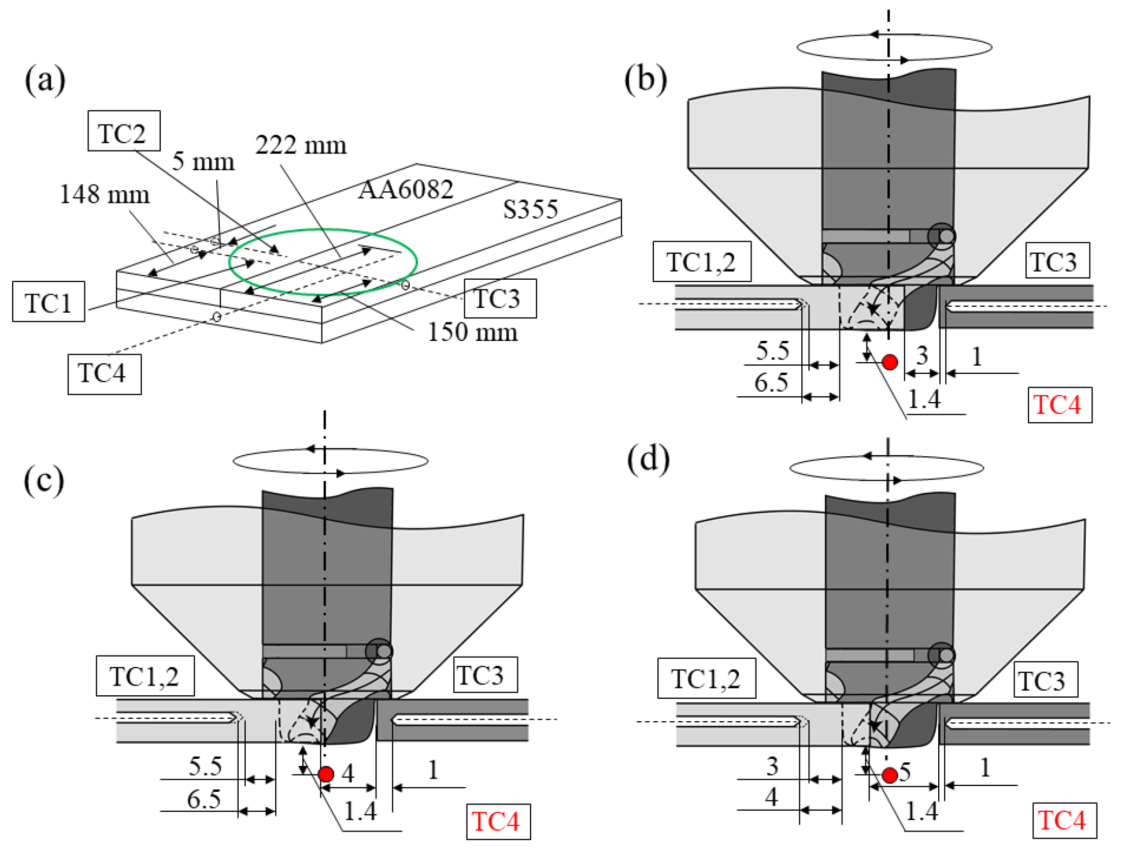
As a starting point, three exploratory test welds, produced under identical operational conditions as those listed in Table 4, were first sectioned and then examined metallographically to determine the exact position of the outer border area of the EZ on the RS of the joints. This examination revealed that the closest position inside the aluminium plates in which the thermocouples could be safely located without risking having them destroyed during the welding operation was 5.5 mm from the outer edge of the submerged rotating pin tip in Series I and II, and 3.0 mm from the outer edge of the submerged rotating pin tip in Series III. On the other hand, the thermocouples in the steel plates placed on the AS of the joints could safely be placed 1 mm outside the steel groove wall because the rotating pin tip, in the present experimental set-up, was just supposed to scribe the steel without actually machining it.
Based on these exploratory experiments, the final sets of test plates, provided with pre-drilled holes for the Ø1 mm thin type-K (chromel-alumel) thermocouples, were subsequently produced in accordance with the target thermocouple positions for Series I, II and III. The positions are shown in Figure 6. In all three series the first two thermocouples (TC1 and TC2) are placed in the aluminium plate on the RS of the joints, with TC1 placed 1 mm behind TC2. Moreover, a third thermocouple (TC3) is positioned in the steel plate on the AS of the joints. In addition, a fourth thermocouple (TC4) is placed in the steel backing about 1.4 mm beneath its surface to evaluate how much of the supplied heat that is actually transferred from the weld root region and to the underlying backing.
Prior to the welding operation, the thermocouples were inserted into these pre-drilled holes and properly fasted to avoid any retraction during the operation, using a copper paste to improve the thermal contact between the thermocouples and the different BMs. Subsequently, the different plate combinations (one at the time) were mounted in a fixture and butt welded using the operational conditions listed in Table 4. During welding the temperature-time histories were recorded employing a digital data logger with a total capacity of eight thermocouples. The applied sampling interval was 0.1 s, which allowed the thermal cycles to be collected with the required degree of accuracy. After welding the plates were sectioned to check that the real positions of the thermocouples were in accordance with the target positions shown in Figure 6.

3.4. Hardness Measurements

After the welding operation, cross-sectional samples were extracted from different parts of the welds and made ready for macro-imaging and Vickers hardness testing using standard preparation techniques. The transverse hardness measurements were made after complete NA (i.e., after 7 days of RT storage), in accordance with ASTM standard E92-17 [37], using a Mitutoyo Micro Vickers hardness testing machine (Kanagawa, Japan) and a constant load of 1 kg. The distance between each indentation was 0.5 mm. The hardness measurements were carried out along the horizontal mid-section of the joints. In total, three individual test series were conducted on each weld.

3.5. Scanning Electron Microscopy

Finally, scanning electron microscope (SEM) examinations of the Al-steel interfaces were conducted on mechanically polished cross sections to determine the mean thickness of the IMC layer along the Al-steel interface in each weld. These examinations were done using a FEI Quanta FEG 650 SEM(London, UK) and an acceleration voltage of 5 kV.

4. Experimental Validation of the Process Model

The direct coupling between the frictional heating model and the FE heat flow model allows the net power input q 0 during welding to be calculated based on a comparison between measured and predicted thermal cycles at the different thermocouple positions indicated in Figure 6. Provided that the thermal program can be adequately predicted for all three welds at the same time as the calculated values for q 0 are physically reasonable, it means that both models can be used, without further improvements, to predict the corresponding hardness and interface microstructure fields as well.

4.1. Predictive Power of Combined Heat Generation and Heat Flow Models

Figure 7 shows a comparison between measured and predicted thermal cycles for the different series and thermocouple positions outlined in Figure 6, whereas Figure 8 displays a plot of the calculated values for the net power input q 0 as a function of the extruder travel speed v .
Referring first to Figure 7, the FE heat flow model is seen to reproduce the measured thermal cycles surprisingly well for all three welds, although the agreement between some of the parallels is not perfect. This shows that the model, in its present form, is sufficiently relevant and comprehensive to be used in subsequent simulations of the thermal fields both in the aluminium plate on the RS of the joint, in the steel plate on the opposite side, as well as in the underlying steel backing.
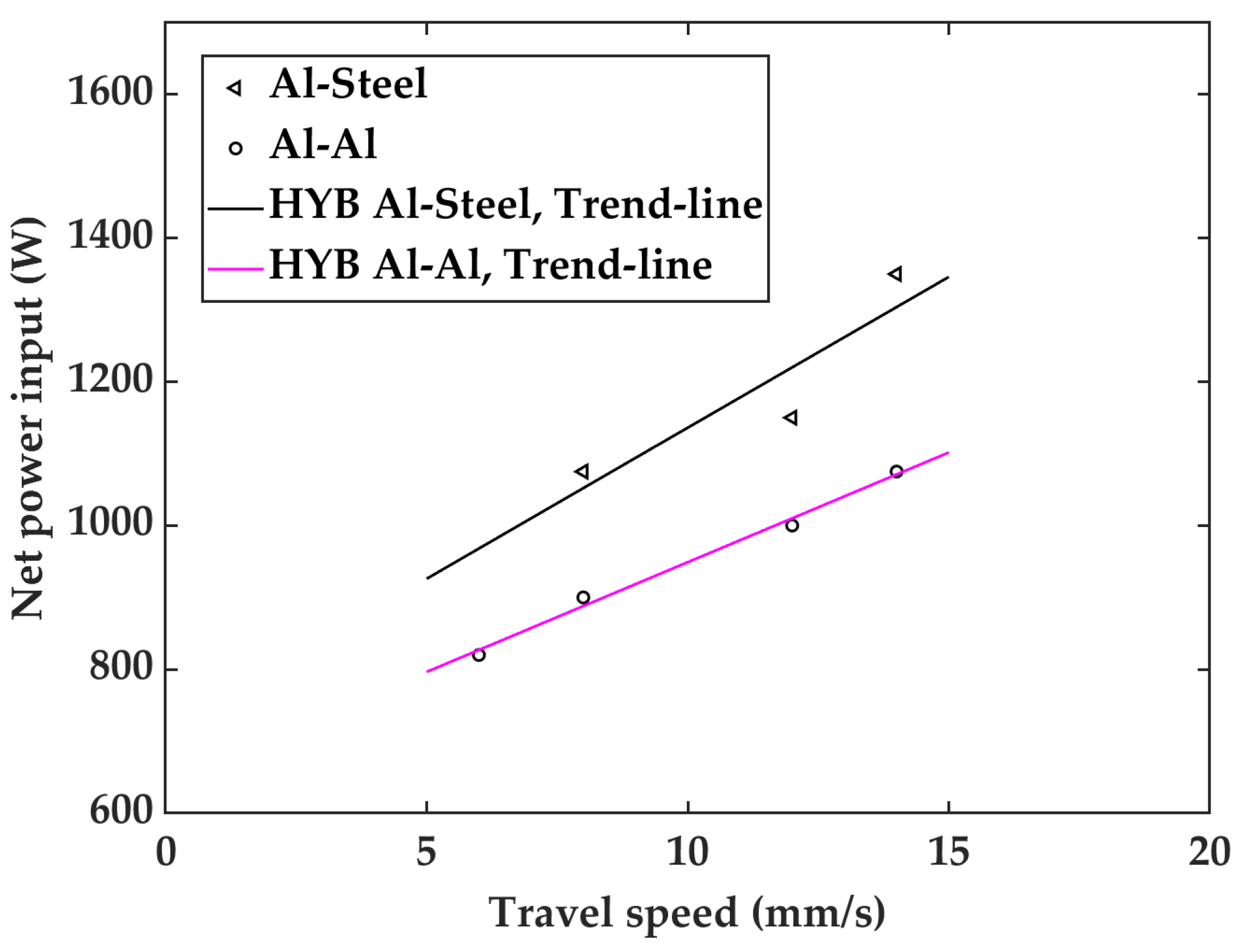
The corresponding calculated values for the net power input q 0 are shown in Figure 8. Specifically, in Series I, II and III the calculated values for the net power input were 1350, 1075, and 1150 W, respectively. It is interesting to observe that q 0 increases with increasing extruder travel speeds. This predicted behaviour is physically reasonable and a consequence of how the HYB process control system works [11,23]. For example, in situations where the increase in the extruder travel speed is not compensated for by a corresponding increase in the pin rotational speed, as in Series I, II and III, one would intuitively expect that a higher spindle torque is needed to plastically deform or scribe the colder BMs being in contact with the rotating pin. This, in turn, will raise the total power consumption and thus the net power input during welding and trigger a response similar to that predicted in Figure 8.
Note that the same type of behaviour as the one shown in Figure 8 has also been reported for FSW of aluminium alloys [38,39,40] as well as for monometallic Al-Al HYB butt welding [23]. However, by comparing the two trend-lines in Figure 8 it appears that the net power input q 0 is somewhat higher in the Al-steel HYB butt welding case than in monometallic Al-Al butt welding for a given extruder travel speed. This difference reflects the extra torque being needed to overcome the higher shear forces involved when the rotating pin scribes the underlying steel plate surfaces on the AS of the joint, leading to a corresponding increase in the total power input W t [16]. Hence, the indications are that the thermal efficiency factor η of the HYB PinPoint extruder during Al-steel butt welding, as given by the ratio between q 0 and W t is similar to that previously reported for monometallic Al-Al butt welding, i.e., barely 30% of the total extruder power input [23,24].

4.2. Predictive Power of Combined Microstructure and Strength Evolution Models

As already stated in Section 2.1, the Al-BM on the RS of the joint will be dragged along with the rotating pin and deposited in the groove behind, where bonding with the FM occurs inside the EZ [13,14,15]. Therefore, in view of the thermomechanical treatment that the Al-BM and the Al-FM undergo in the HYB case, it is reasonable to assume that the properties achieved immediately after welding are the result of two competing processes, i.e., softening due to dissolution of the hardening β / / precipitates and strengthening due to dislocation hardening [29]. However, because the observed hardness drop, both within the HAZ and the EZ, is significant, the former process is, by far, the dominating one determining the final joint strength [14].
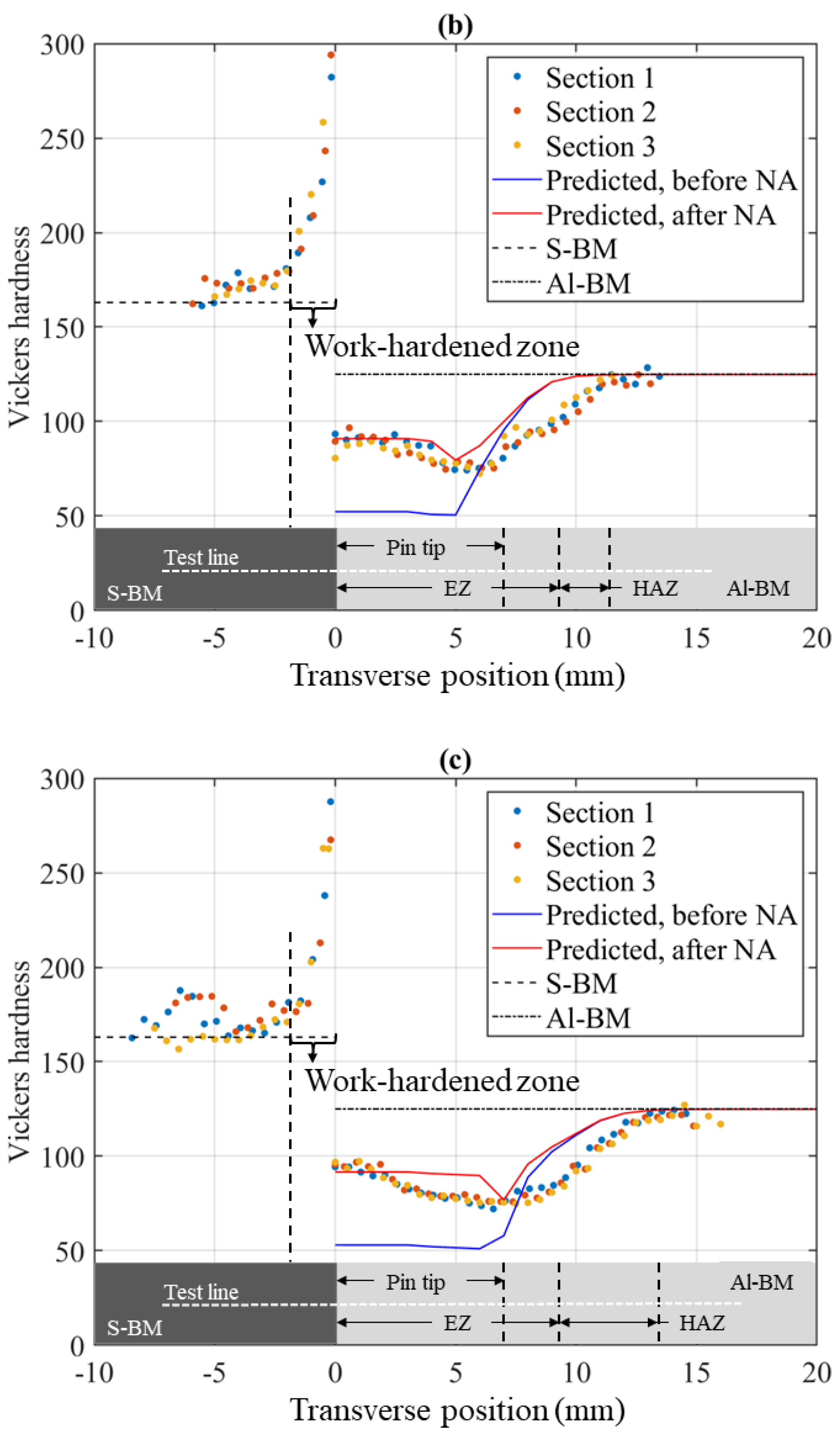
Still, the dislocations being generated due to the imposed plastic deformation caused by the rotating action of the pin can affect the softening behaviour in several other ways that are not accounted for by the NaMo module in WELDSIM. First of all, pipe diffusion through the core of the dislocations needs to be compensated for through the use of a higher diffusion coefficient for the rate controlling element magnesium D M g in aluminium due to the accelerating effect it has on the β / / dissolution kinetics [29]. In the present simulations this has been done by reducing the activation energy Q d in the expression for D M g from 130 to 125 kJ/mol to make sure that the initial hardness drops within the soft zone immediately after welding is adequately captured. Secondly, it is necessary to account for the decelerating effect that the dislocations have on the GP-zone formation during subsequent NA by virtue of their ability to act as sinks for excess vacancies/vacancy clusters in the aluminium matrix. Because the role of the vacancies is to catalyse the nucleation of the hardening GP-zones [29], a drop in the matrix concentration will limit the extent of strength recovery that occurs inside the EZ. The pragmatic way of handling this problem in WELDSIM is to reduce the default value in the input file for the maximum yield stress increase after complete natural ageing Δ σ max r e f from 116 to 106 MPa [27]. By implementing these two new values for Q d and Δ σ max r e f in WELDSIM, keeping all other input parameters unchanged, the hardness profiles across the HAZ and the EZ of the three Al-steel HYB butt welds have been calculated using the NaMo module. The results are presented in Figure 9.
It is evident from these plots that the dissolution behaviour of the hardening β / / precipitates is adequately captured by WELDSIM, eventually leading to full reversion at about 5 to 6 mm from the Al-steel interface inside the EZ. Apparently, all three Al-steel HYB butt welds reveal similar softening behaviour. The only difference is that the total width of the HAZ is seen to be somewhat larger in Series III compared to the two other ones. This observation is not surprising when it is realized that a decrease in the extruder travel speed in the HYB case is not necessarily fully compensated for by a corresponding decrease in the net power input q 0 (see Figure 8). Therefore, the different joints will reveal minor differences in the heat input per unit length of the welds E , as determined by the q 0 / v ratio, and thus display a natural spread in their thermal programs and hardness fields.
Furthermore, both within the partially and fully reverted regions of the joints significant strength recovery is seen to occur by GP-zone formation during subsequent NA. This means that the locus of the minimum hardness becomes slightly shifted towards the outer boundary of the EZ after complete NA. Nevertheless, although the hardness data in Figure 9 show that the agreement between predictions and measurements is not perfect, the NaMo-simulations seem to capture both the minimum strength level as well as the total width of the soft zone on the aluminium side of the joints reasonably well for all three welds. These parameters are the two most important ones determining the maximal load-bearing capacity of corresponding monometallic Al-Al butt joints [27] and will therefore also be the proper strength markers for the Al-steel HYB welds.
On the AS of the joints the work-hardened zone is seen to extent about 2 mm into the S-BM. The peak hardness is observed at the Al-steel interface, reaching values typically in the range from about 275 to 300 HV1.

4.3. Predictive Power of Isokinetic Diffusion Model for the IMC Formation

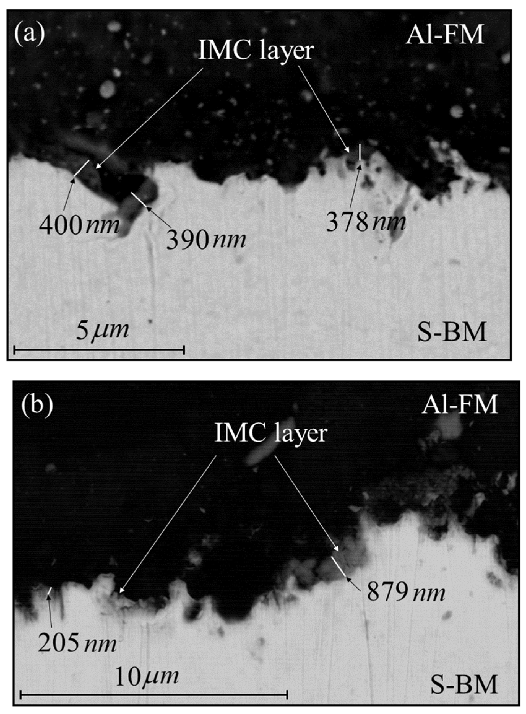
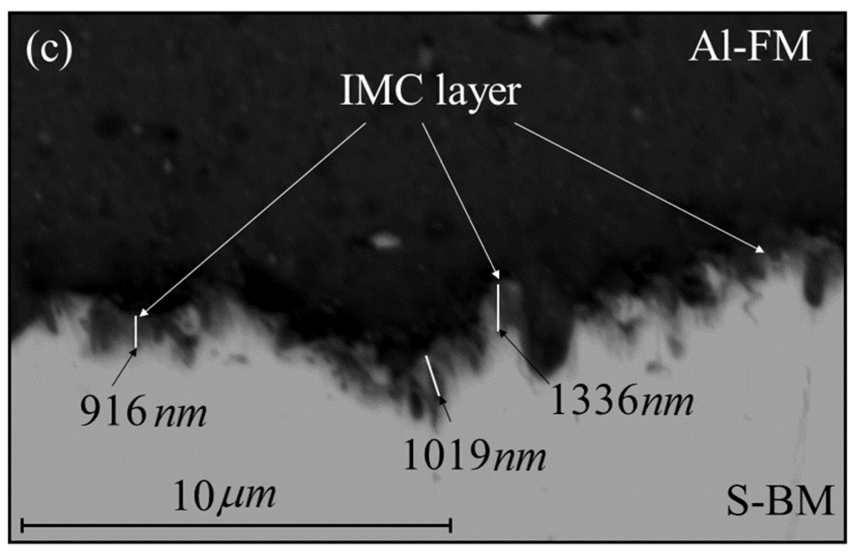
Figure 10 displays the SEM backscattered electron (BSE) images of the Al-steel interface taken from the mid-section of the HYB welds. In all three cases bonding is seen to occur by a combination of mechanical interlocking and IMC formation. In Series I and II the IMC layer thickness varies between 0.2 and 0.9 µm, whereas in Series III it is slightly thicker (i.e., in the range from 0.9 and 1.3 µm). It is believed that these minor differences in the layer thickness reflect the previously mentioned variations in the gross heat input E and thus the thermal program between the welds.
The next step is to calibrate the reference time t r in the expression for the time constant t * in the isokinetic diffusion model against an experimental value for the layer thickness X . Taking, for example, 1 µm as a typical value for X in Series III, the back-calculations yield a t r value of about 3 s when the reference temperature T r in the underlying isothermal growth model is fixed to 400 °C. Then, using this default value for t r in the subsequent calculations, the corresponding predicted values for X in Series I and II becomes 0.66 and 0.50 μm, respectively. Therefore, in a calibrated form the isokinetic diffusion model adequately captures the pertinent variations in the IMC layer thickness among the welds, as observed experimentally.

5. Applications of the Process Model

Because both the thermal, microstructure and strength evolutions fields are quite similar in all three Al-steel HYB butt welds, simulations based on the operational conditions employed in Series II will be used to shed light upon the underlying physical phenomena involved and how the process model can be employed to disclose their mutual interactions.

5.1. Temperature Distribution during Al-Steel HYB Butt Welding

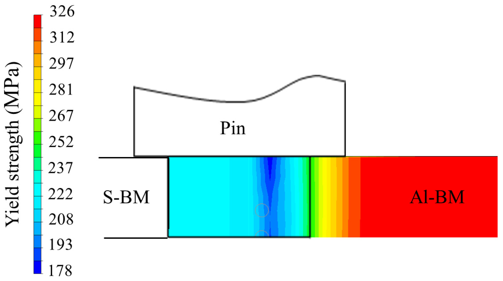
Figure 11 displays predicted isothermal contours at the surface of the 4 mm thick butt-welded aluminium and steel plates in Series II. The characteristic asymmetrical thermal field of the Al-steel weld is clearly visible in this surface contour plot, showing that most of the absorbed heat diffuses into and through the aluminium plate. This observation is not surprising, considering the fact that the thermal diffusivity of aluminium is approximately ten times higher than that of steel [31]. At the Al-steel interface, the temperature reaches a value of about 400 °C. In the middle of the EZ the peak temperature is close to 460 °C. It then drops in an asymmetrical manner with increasing distance from the heat centre on both sides of the joint. Because of this the transverse thermal gradient inside the hottest part of the EZ is seen to be of the order of 20 °C per mm, whereas on the steel side next to the pin the gradient is nearly 4 times higher.
Figure 12 shows a corresponding plot of the predicted peak temperature contours in the transverse direction of the Al-steel HYB butt weld. Because the cross sectional isotherms appear to be straight, it means that essentially no thermal gradients exist in the through-thickness direction of the weld [32]. This is also the case inside the central parts of the EZ, where most of the heat loss to the underlying steel backing occurs. Hence, the present experimental conditions favour two-dimensional heat flow, both in the aluminium and steel plates.

5.2. Strength Distribution inside the Al-Steel HYB Butt Weld

In most Al-steel butt welds the tensile strength is limited by the interfacial bond strength owing to the insidious nature of the hard and brittle IMC layer [2,41]. However, the strength limitation can be overcome if bonding instead occurs by a combination of microscale mechanical interlocking and IMC formation, where the IMC layer is in the sub-micrometer range (<1 µm), as in the HYB case. This type of microstructure, which provides a high intrinsic resistance against cracking, is unique for the HYB process and reflects its characteristic low interface temperature of about 400 °C, preventing excessive growth of the IMC layer. Therefore, under welding conditions which apply to the third generation Al-steel HYB butt welds, as dealt with here, the tensile strength is actually determined by the minimum strength level inside either the HAZ or the EZ on the aluminium side of the joint [14]. This makes simulations of the yield strength distribution in the transverse direction particularly relevant when it comes to evaluating the maximal load-bearing capacity of such joints.
Figure 13 shows predicted yield strength contours in the transverse direction of the butt-welded aluminium and steel plates in Series II. Because the applied experimental conditions promote two-dimensional heat flow, the present Al-steel HYB butt weld displays essentially straight strength contours in the through-thickness direction. Therefore, the locus of the minimum yield strength will coincide with that of the minimum hardness in Figure 9, reaching a value of 178 MPa inside the EZ after complete NA. This predicted value for the joint strength is slightly higher than that observed in real testing of flush-machined specimens extracted from the corresponding third generation Al-steel HYB butt weld (i.e., 166 MPa) [14].

5.3. Case Study on Optimising the Load-Bearing Capacity of Al-Steel HYB Butt Welds

In the HYB case both the drive spindle rotational speed N s (which controls the FM deposition rate), the extruder travel speed v and the groove width k must be properly pre-set to achieve adequate groove filling and thus a sound weld [16]. In the present investigation this is done by first fixing N s and then, based on simple mass balance calculations, selecting the proper combinations of v and k that provide full groove filling.
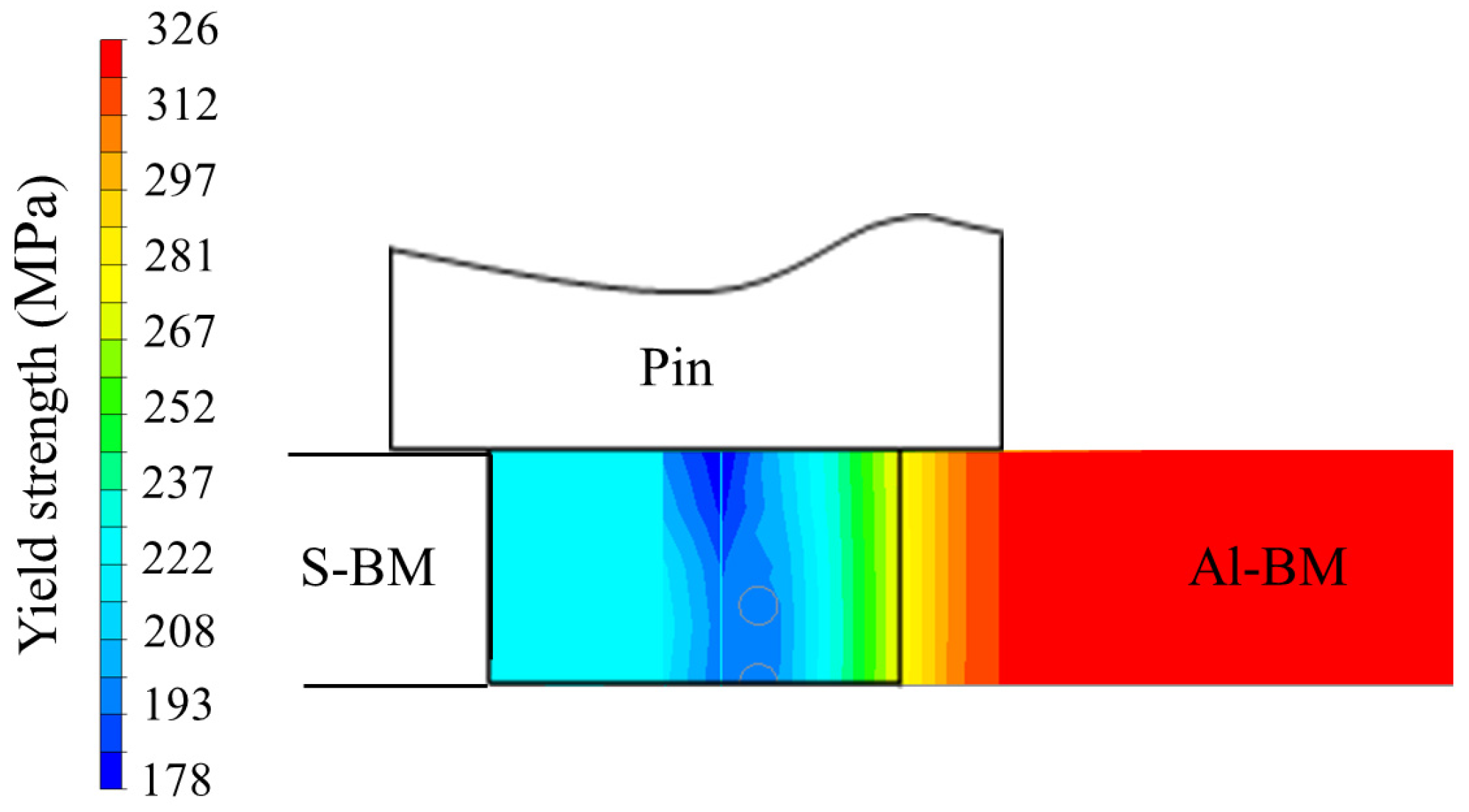
The problem with this approach is that an increase in the extruder travel speed is always accompanied by a corresponding increase in the net power input q 0 (see Figure 8). Hence, all three joints included in the present study reveal essentially the same heat input per unit length of the welds E and thus similar thermal programs and yield strength distributions. Therefore, in order to increase in the yield strength of the present Al-steel HYB butt welds beyond the 178 MPa limit a decrease in E through a reduction in N s could be a viable approach. Still, this is a hypothesis that needs to be substantiated further through simulations before it can be put to the test. However, since N s also controls the FM mass flow rate, a pre-condition for a successful outcome is that the Ø1.4 mm FW used in the present experimental set-up can be replaced by a corresponding Ø1.6 mm FW to maintain a constant flow of FM into the groove and thus adequate groove filling. This is fully possible using the current version of the PinPoint extruder [21] and would, in case, allow N s in Series II to be reduced from 350 to 260 RPM without having to change either v or k . The results from the WELDSIM predictions of the alternative experimental set-up for Series II are presented in Figure 14.
It follows from the yield strength contour plot in Figure 14 that a reduction in the drive spindle rotational speed from 350 to 260 RPM will not significantly increase the minimum yield strength level inside the EZ, but only make the soft zone slightly narrower. Therefore, the possibility of raising the joint yield strength beyond the 178 MPa limit by manipulating either N s or v seems difficult, which calls for a new approach. One possible solution could be to simultaneously deposit, say, a 1 mm thick weld reinforcement on the top of the EZ to increase its cross-sectional area. The use of a stationary housing provided with a separate die at the rear for partial outlet of the extrudate on the top of the weld has already been used in a number of other studies with success [11]. If the steel backing at the same time is replaced by a bobbin pin, as frequently done in HYB butt welding operations to secure two-dimensional heat flow and eliminate root crack problems, a strength distribution inside the EZ similar to the one shown previously in Figure 13 or Figure 14 is within the reach. It is believed that the combination of a weld reinforcement and straight yield strength contours inside the EZ will provide the necessary conditions for raising the load-bearing capacity of the Al-steel HYB butt welds beyond the 178 MPa limit. Still, this needs to be verified through real tensile testing in combination with digital image correlation (DIC) analysis to disclose the actual yield strength inside the aluminium part of the joint being produced in accordance with the new experimental set-up [14].

6. Conclusions

The basic conclusions that can be drawn from this investigation are the following:
(1)
The numerical code WELDSIM has proved useful to capture both the temperature-time pattern, the interface microstructure development and the yield strength evolution in different Al-steel butt welds made by HYB. In WELDSIM the finite element (FE) heat flow model is coupled to a frictional heating model, an isokinetic diffusion model for the interfacial intermetallic compound (IMC) formation and a nanostructure model (NaMo) for simulating reversion and re-precipitation of hardening phases inside the aluminium part of the joints during welding and subsequent natural ageing (NA).
(2)
In total, three different exploratory butt welding trials have been conducted (referred to as Series I, II and III), using 4 mm thick rolled plates of S355 steel and AA6082-T6 as base metals (BMs). As a starting point, the recorded thermal data, as obtained for in-situ thermocouple measurements, are used to calibrate the coupled frictional heating and FE heat flow models. Subsequently, the measured data for the IMC layer thickness at Al-steel interface along with the transverse HAZ hardness profiles are employed for validating the isokinetic IMC diffusion model and the NaMo model, respectively.
(3)
In a calibrated form WELDSIM adequately reproduces the thermal program during Al-steel butt welding using the HYB process. The characteristic asymmetrical thermal field of the Al-steel butt welds is clearly visible in the computed contour plots, showing that most of the absorbed heat diffuses into and through the aluminium plate. At the Al-steel interface the simulation results show that the temperature reaches a value close to 400 °C.
(4)
In Al-steel HYB butt welds, where the interfacial bond strength is not a limiting factor, the tensile strength will be determined by the minimum strength level inside either the HAZ or the extrusion zone (EZ) on the aluminium side of the joints. This makes simulations of the yield strength distribution in the transverse direction particularly relevant when it comes to evaluating the maximal load-bearing capacity of such joints. However, the results reveal no such positive effect of lowering the gross heat input besides that the width of the soft zone becomes slightly narrower. An alternative approach to solve this intricate softening problem, based on the results obtain in the case study, is presented towards the end of the paper.

Author Contributions

Conceptualization, F.L. and Ø.G.; methodology, F.L. and Ø.G.; software, F.L. and H.G.F.; validation, F.L. and Ø.G.; formal analysis, F.L. and Ø.G.; investigation, F.L., Ø.G. and A.C.; resources, F.L., Ø.G., P.F. and F.B.; data curation, F.L.; writing—original draft preparation, F.L. and Ø.G.; writing—review and editing, F.L. and Ø.G; supervision, F.B.; project administration, F.L., Ø.G., P.F. and F.B.; funding acquisition, F.B. and Ø.G. All authors have read and agreed to the published version of the manuscript.

Funding

This research received no external funding.

Institutional Review Board Statement

Not applicable.

Informed Consent Statement

Not applicable.

Acknowledgments

The authors acknowledge the financial support from The Norwegian Research Council through the BOOST project and the funding provided by HyBond AS and NTNU Aluminium Product Innovation Center (NAPIC). They are also indebted to Tor Austigard of HyBond AS for valuable assistance in planning the in-situ thermocouple experiments and producing the three Al-steel HYB butt welds examined in the present investigation.

Conflicts of Interest

The authors declare no conflict of interest.

Appendix A

Symbols
d plates thickness (mm)
D M g diffusion coefficient of magnesium in aluminium (m2/s)
E gross heat input during extrusion and joining (kJ/mm)
h 1 difference between tool tip diameter and groove width (mm)
h 2 difference between tool shoulder diameter and groove width (mm)
k I-groove width (mm)
N s drive spindle rotational speed (RPM)
d m / d t filler metal mass flow rate (kg/s)
q 0 net power input (W)
q t i p tip contribution to the net power input (W)
q s h shoulder contribution to the net power input (W)
q F M filler metal contribution to the net power input (W)
Q d activation energy for diffusion of magnesium in aluminium (kJ/mol)
r t i p radius of the tip (mm)
r s h radius of the shoulder (mm)
T int temperature at tool-matrix interface (°C)
t * time constant in diffusion model for the IMC formation (s)
t r reference time in expression for t * (s)
T temperature (°C)
T F M filler metal temperature (°C)
T r reference temperature in expression for t * (°C)
v extruder travel speed (mm/s)
W t total power input during extrusion and welding (W)
X IMC layer thickness (µm)
X r reference value for the IMC layer thickness (µm)
β / / hardening precipitates in Al-Mg-Si alloys
η thermal efficiency factor of PinPoint extruder
ω angular rotation speed (rad/s)
Δ σ max r e f maximum yield stress increase in reference alloy after natural ageing
σ i intrinsic yield stress of pure aluminium (MPa)
σ p contribution form precipitation hardening in NaMo (MPa)
σ s s contribution from solid solution hardening in NaMo (MPa)
σ y aluminium yield strength (MPa)
τ local yield shear stress at tool/aluminium interface (MPa)
Abbreviations
Ac1lowest temperature at which phase transformation occurs on heating
Al-Almonometallic Al-Al component
Al-BMaluminium base metal
Al-FMaluminium filler metal
Al-FWaluminium filler wire
Al-steel aluminium-steel component or aluminium-steel interface
ASadvancing side
BMbase metal
BSE backscattered electrons
CMTWcold metal transfer welding
DICdigital image correlation
EZextrusion zone
FEfinite element
FMfiller metal
FSWfriction stir welding
FWfiller wire
GMAWgas metal arc welding
GP-zonesGuinier–Preston zones
HAZheat-affected zone
HYBhybrid metal extrusion and bonding
HVVickers hardness
IMCintermetallic compound
LBWlaser beam welding
NAnatural ageing
NaMonanostructure model
RSretreating side
RTroom temperature
S-BMsteel base metal
SEMscanning electron microscope
TC1thermocouple 1
TC2thermocouple 2
TC3thermocouple 3
TC4thermocouple 4

References

  1. Robson, J.; Panteli, A.; Prangnell, P.B. Modelling intermetallic phase formation in dissimilar metal ultrasonic welding of aluminium and magnesium alloys. Sci. Technol. Weld. Join. 2012, 17, 447–453. [Google Scholar] [CrossRef]
  2. Cai, W.; Daehn, G.; Vivek, A.; Li, J.; Khan, H.; Mishra, R.S.; Komarasamy, M. A state-of-the-art review on solid-state metal joining. J. Manuf. Sci. Eng. 2019, 141, 31012. [Google Scholar] [CrossRef]
  3. Gullino, A.; Matteis, P.; D’Aiuto, F. Review of aluminium-to-steel welding technologies for car-body applications. Metals 2019, 9, 315. [Google Scholar] [CrossRef]
  4. Joseph, A.; Rai, S.K.; Jayakumar, T.; Murugan, N. Evaluation of residual stresses in dissimilar weld joints. Int. J. Press. Vessel. Pip. 2005, 82, 700–705. [Google Scholar] [CrossRef]
  5. Wan, L.; Huang, Y. Friction stir welding of dissimilar aluminum alloys and steels: A review. Int. J. Adv. Manuf. Technol. 2018, 99, 1781–1811. [Google Scholar] [CrossRef]
  6. Uematsu, Y.; Kakiuchi, T.; Tozaki, Y.; Kojin, H. Comparative study of fatigue behaviour in dissimilar Al alloy/steel and Mg alloy/steel friction stir spot welds fabricated by scroll grooved tool without probe. Sci. Technol. Weld. Join. 2012, 17, 348–356. [Google Scholar] [CrossRef]
  7. Ohhama, S.; Hata, T.; Yahaba, T.; Kobayashi, T.; Miyahara, T.; Sayama, M. Application of an FSW Continuous Welding Technology for Steel and Aluminum to an Automotive Subframe; SAE Technical Paper; SAE International: Warrendale, PA, USA, 2013. [Google Scholar] [CrossRef]
  8. Colwell, K.C. Two metals enter, one leaves: The miracle of friction stir welding. Car Driv. 2013, 15. [Google Scholar]
  9. Kusuda, Y. Honda develops robotized FSW technology to weld steel and aluminum and applied it to a mass-production vehicle. Ind. Robot. Int. J. 2013, 40, 208–212. [Google Scholar] [CrossRef]
  10. Sandnes, L.; Grong, Ø.; Torgersen, J.; Welo, T.; Berto, F. Exploring the hybrid metal extrusion and bonding process for butt welding of Al–Mg–Si alloys. Int. J. Adv. Manuf. Technol. 2018, 98, 1059–1065. [Google Scholar] [CrossRef]
  11. Grong, Ø.; Sandnes, L.; Ferro, P.; Berto, F. Hybrid Metal Extrusion & Bonding. In Handbook of Welding (HOW-2021); Nova Science Publishers, Inc.: Hauppauge, NY, USA, 2021; pp. 2–54. [Google Scholar]
  12. Grong, Ø.; Sandnes, L.; Bergh, T.; Vullum, P.E.; Holmestad, R.; Berto, F. An Analytical Framework for Modelling Intermetallic Compound (IMC) Formation and Optimizing Bond Strength in Aluminium-Steel Welds. Mater. Des. Process. Commun. 2019, 1, e57. [Google Scholar] [CrossRef] [Green Version]
  13. Bergh, T.; Sandnes, L.; Johnstone, D.N.; Grong, Ø.; Berto, F.; Holmestad, R.; Midgley, P.A.; Vullum, P.E. Microstructural and mechanical characterization of a second generation hybrid metal extrusion & bonding aluminium-steel butt joint. Mater. Charact. 2021, 173, 110761. [Google Scholar] [CrossRef]
  14. Sandnes, L.; Bergh, T.; Grong, Ø.; Holmestad, R.; Vullum, P.E.; Berto, F. Interface microstructure and tensile properties of a third generation aluminium-steel butt weld produced using the Hybrid Metal Extrusion & Bonding (HYB) process. Mater. Sci. Eng. A 2021, 809, 140975. [Google Scholar] [CrossRef]
  15. Sandnes, L.; Welo, T.; Grong, Ø.; Berto, F. On the fatigue properties of a third generation aluminium-steel butt weld made by hybrid metal extrusion & bonding (HYB). Int. J. Fatigue 2021, 155, 106586. [Google Scholar] [CrossRef]
  16. Grong, Ø.; Sandnes, L.; Berto, F. A status report on the hybrid metal extrusion & bonding (HYB) process and its applications. Mater. Des. Process. Commun. 2019, 1, e41. [Google Scholar] [CrossRef]
  17. Frigaard, Ø.; Grong, Ø.; Midling, O.T. A process model for friction stir welding of age hardening aluminium alloys. Metall. Mater. Trans. A 2001, 32, 1189–1200. [Google Scholar] [CrossRef]
  18. Khandkar, M.Z.H.; Khan, J.A.; Reynolds, A.P. Prediction of temperature distribution and thermal history during friction stir welding: Input torque based model. Sci. Technol. Weld. Join. 2003, 8, 165–174. [Google Scholar] [CrossRef]
  19. El-Moayed, M.H.; Shash, A.Y.; Abd Rabou, M.; El-Sherbiny, M.G.D. A coupled statistical and numerical analysis of the residual properties of AA6063 friction stir welds. J. Adv. Join. Process. 2021, 3, 100042. [Google Scholar] [CrossRef]
  20. Fjær, H.G.; Bjørneklett, B.; Myhr, O.R. Microstructure based modelling of Al-Mg-Si alloys in development of local heating processes for automotive structures. In Proceedings of the 2005 TMS Annual Meeting, San Francisco, CA, USA, 13–17 February 2005. [Google Scholar]
  21. Tang, X.; Fjær, H.G. Integrated Forming, Welding and Crash Simulations for an Aluminum Crash Management System. In Proceedings of the International Design Engineering Technical Conferences and Computers and Information in Engineering Conference, Boston, MA, USA, 2–5 August 2015; Volume 57045. [Google Scholar] [CrossRef]
  22. Leoni, F.; Grong, Ø.; Ferro, P.; Berto, F. Simulating the dependence of the filler wire feeding on the wire size in the hybrid metal extrusion & bonding (HYB) process. Procedia Struct. Integr. 2020, 26, 321–329. [Google Scholar] [CrossRef]
  23. Leoni, F.; Grong, Ø.; Ferro, P.; Berto, F. A Semi-Analytical Model for the Heat Generation during Hybrid Metal Extrusion and Bonding (HYB). Materials 2021, 14, 170. [Google Scholar] [CrossRef]
  24. Leoni, F.; Grong, Ø.; Fjær, H.G.; Ferro, P.; Berto, F. A First Approach on Modelling the Thermal and Microstructure Fields During Aluminium Butt Welding Using the HYB PinPoint Extruder. Procedia Struct. Integr. 2020, 28, 2253–2260. [Google Scholar] [CrossRef]
  25. Myhr, O.R.; Grong, Ø.; Andersen, S.J. Modelling of the age hardening behaviour of Al–Mg–Si alloys. Acta Mater. 2001, 49, 65–75. [Google Scholar] [CrossRef]
  26. Myhr, O.R.; Grong, Ø.; Fjær, H.G.; Marioara, C.D. Modelling of the microstructure and strength evolution in Al–Mg–Si alloys during multistage thermal processing. Acta Mater. 2004, 52, 4997–5008. [Google Scholar] [CrossRef]
  27. Myhr, O.R.; Grong, Ø. Novel modelling approach to optimization of welding conditions and heat treatment schedules for age hardening Al alloys. Sci. Technol. Weld. Join. 2009, 14, 321–332. [Google Scholar] [CrossRef]
  28. Myhr, O.R.; Grong, Ø.; Pedersen, K.O. A combined precipitation, yield strength, and work hardening model for Al-Mg-Si alloys. Metall. Mater. Trans. A 2010, 41, 2276–2289. [Google Scholar] [CrossRef]
  29. Myhr, O.R.; Grong, Ø.; Schäfer, C. An extended age-hardening model for Al-Mg-Si alloys incorporating the room-temperature storage and cold deformation process stages. Metall. Mater. Trans. A 2015, 46, 6018–6039. [Google Scholar] [CrossRef]
  30. Grong, Ø. Metallurgical Modelling of Welding; Institute of Materials: London, UK, 1997. [Google Scholar]
  31. Ramachandran, K.K.; Murugan, N.; Kumar, S.S. Friction stir welding of aluminum alloy AA5052 and HSLA steel. Weld. J. 2015, 94, 291–300. [Google Scholar]
  32. MSCsoftware. 2021. Available online: https://www.mscsoftware.com/ (accessed on 26 August 2022).
  33. Outinen, J.; Kesti, J.; Mäkeläinen, P. Fire design model for structural steel S355 based upon transient state tensile test results. J. Constr. Steel Res. 1997, 42, 161–169. [Google Scholar] [CrossRef]
  34. Goyal, R.; Johnson, E.; El-Zein, M. A model equation for the convection coefficient for thermal analysis of welded structures. In Trends in Welding Research: Proceedings of the 8th International Conference, 1–6 June 2008; ASM International: Pine Mountain, GA, USA, 2009; p. 321. [Google Scholar]
  35. Goldak, J.; Chakravarti, A.; Bibby, M. A new finite element model for welding heat sources. Metall. Trans. B 1984, 15, 299–305. [Google Scholar] [CrossRef]
  36. GLview. 2021. Available online: https://ceetron.com/ceetron-glview-inova/ (accessed on 26 August 2022).
  37. ASTM E92-17; Standard Test Methods for Vickers Hardness and Knoop Hardness of Metallic Materials. ASTM International: West Conshohocken, PA, USA, 2017.
  38. Jacquin, D.; De Meester, B.; Simar, A.; Deloison, D.; Montheillet, F.; Desrayaud, C. A simple Eulerian thermomechanical modeling of friction stir welding. J. Mater. Process. Technol. 2011, 211, 57–65. [Google Scholar] [CrossRef]
  39. Saravanakumar, R.; Rajasekaran, T.; Pandey, C.; Menaka, M. Influence of tool probe profiles on the microstructure and mechanical properties of underwater friction stir welded AA5083 material. J. Mater. Eng. Perform. 2022, 1–18. [Google Scholar] [CrossRef]
  40. Saravanakumar, R.; Rajasekaran, T.; Pandey, C.; Menaka, M. Mechanical and microstructural characteristics of underwater friction stir welded AA5083 armor-grade aluminum alloy joints. J. Mater. Eng. Perform. 2022, 1–14. [Google Scholar] [CrossRef]
  41. Grzegorz Rogalski, G.; Swierczy, A.; Landowski, M.; Fydryc, D. Mechanical and microstructural characterization of TIG welded dissimilar joints between 304L austenitic stainless steel and Incoloy 800HT nickel alloy. Metals 2020, 10, 559. [Google Scholar] [CrossRef]
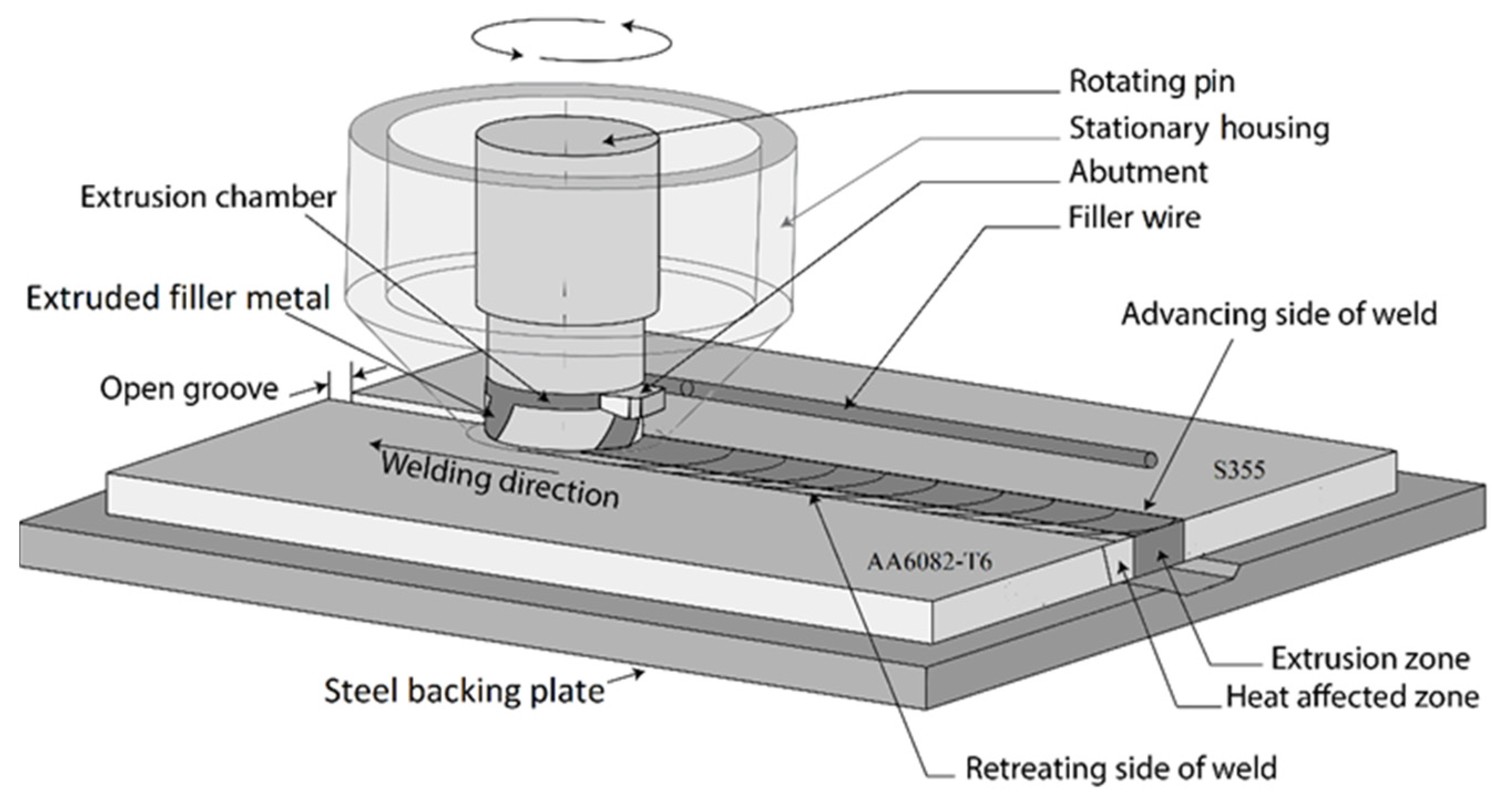
Figure 1. Schematic illustration of Al-steel HYB butt joining. Prior to the operation the two base plates are clamped onto a steel backing with a fixed spacing, where the aluminium plate is placed on the retreating side (RS) and the steel plate on the advancing side (AS) of the joint.
Metals 12 01656 g001
Figure 2. Schematic illustration defining the contact conditions during Al-steel butt welding using the HYB PinPoint extruder; (a) lateral view of the tool inside the groove, (b) Top view of the rotating pin inside the same groove.
Metals 12 01656 g002
Figure 3. Schematic drawings of the rotating pin with its protruding cylindrical tip and flat shoulder. As an aid to the reader, some of the symbols and parameters included in the expression for the net power input are also highlighted.
Metals 12 01656 g003
Figure 4. Mesh employed in the FE heat flow simulations of the Al-steel HYB butt welding operation.
Metals 12 01656 g004
Figure 5. Thermal properties of (a) S-BM and (b) Al-BM used in the FE model.
Metals 12 01656 g005
Figure 6. Sketches showing the target positions reported in mm of the thermocouples used to record the HAZ thermal programs and the corresponding temperature rise in the steel backing for each of the three test series; (a) Thermocouple positions referred to the weld start position, (b) Thermocouple positions referred to the outer edge of the submerged rotating pin tip in Series I, (c) Thermocouple positions referred to the outer edge of the submerged rotating pin tip in Series II and (d) Thermocouple positions referred to the outer edge of the submerged rotating pin tip in Series III. Operational conditions as in Table 4.
Metals 12 01656 g006
Figure 7. Comparison between measured and predicted thermal cycles for the different series and thermocouple positions shown in Figure 6; (a) Series I, (b) Series II and (c) Series III. Operational conditions as in Table 4.
Metals 12 01656 g007
Figure 8. Calculated values for the net power input as a function of the extruder travel speed. The black trend-line drawn through the triangular data points represents Al-steel HYB butt welding and Series I, II and III, whereas the lower pink trend-line refers back to monometallic Al-Al HYB butt welding, as reported previously, data from [23]. Operational conditions as in Table 4.
Metals 12 01656 g008
Figure 9. Summary of the results from the transverse hardness measurements along with the predicted hardness curves from WELDSIM; (a) Series I, (b) Series II and (c) Series III. Note that the hardness measurements are done in the mid-section of the welds on three different sections along the joint line. The WELDSIM predictions refer to simulations carried out both immediately after welding before natural ageing (NA) occurs and following complete NA. Operational conditions as in Table 4.
Metals 12 01656 g009aMetals 12 01656 g009b
Figure 10. SEM BSE images of the IMC layer at the Al-steel interface in the three different HYB welds; (a) Series I, (b) Series II and (c) Series III. The micrographs are taken from the mid-section of the welds. Operational conditions as in Table 4.
Metals 12 01656 g010aMetals 12 01656 g010b
Figure 11. Predicted isothermal contours at the surface of the butt-welded aluminium and steel plates in Series II. Operational conditions as in Table 4.
Metals 12 01656 g011
Figure 12. Predicted peak temperature contours in the transverse direction of the butt-welded aluminium and steel plates in Series II. Colour contours refer to temperature in degrees Celsius. Operational conditions as in Table 4.
Metals 12 01656 g012
Figure 13. Predicted yield strength contours in the transverse direction of the butt-welded aluminium and steel plates in Series II. Colour contours refer to the offset yield strength in MPa. Operational conditions as in Table 4.
Metals 12 01656 g013
Figure 14. Predicted yield strength contours in the transverse direction of a hypothetical 4 mm thick Al-steel HYB butt weld produced under the following operational conditions; extruder travel speed: 12 mm/s, groove width: 4 mm, drive spindle rotational speed: 260 RPM. Note that the colour contours indicated in the image refer to the offset yield strength in MPa.
Metals 12 01656 g014
Table 1. Chemical compositions (in wt. %) of the AA6082-T6 base metal (Al-BM) and the Ø1.4 mm AA6082-T4 filler wire (Al-FW) used in the Al-steel butt welding trials.
MaterialSiMgFeCuMnCrZnTiZrBOthersAl
Al-BM1.140.760.220.060.620.080.090.03--<0.15Balance
Al-FW1.110.610.200.0020.510.14-0.0430.130.0060.029Balance
Table 2. Chemical composition (in wt. %) of the S355 steel base metal (S-BM) used in the Al-steel butt welding trial.
MaterialCSiMnPSCrNiCuAlNbBNFe
S-BM0.0590.010.610.010.0020.030.040.010.0650.02500.003Balance
Table 3. Mechanical properties of the aluminium and steel base materials (Al-BM and S-BM) and the cold-drawn Ø1.4 mm AA6082-T4 filler wire (Al-FW) according to mill certificates.
MaterialYield Strength Ultimate Tensile Strength Elongation
Al-BM324 MPa333 MPa11.8%
S-BM410 MPa481 MPa34.5%
Al-FW367 MPa388 MPa4%
Table 4. Summary of operational conditions employed in Series I, II and III, respectively.
Series No.I-Groove WidthExtruder Travel Speed Spindle Rotational Speed
I 3 mm14 mm/s350 RPM *
II4 mm12 mm/s350 RPM *
III5 mm8 mm/s350 RPM *
* The applied drive spindle rotational speed corresponds to a FW feed rate of about 150 mm/s.
Publisher’s Note: MDPI stays neutral with regard to jurisdictional claims in published maps and institutional affiliations.