Abstract
The automobile industry has been concentrating on developing eco-friendly materials that improve the safety and fuel efficiency of automobiles. Aluminum alloys, well known as lightweight materials, have been studied, particularly as the demand for high-strength and lightweight materials has been increasing. This study focuses on the technique of rheocasting using electromagnetic stirring (EMS), which is a typical semi-solid method for manufacturing aluminum products. Focusing on EMS, the effect of current input methods on the castability, roundness, and mechanical properties of products manufactured by rheocasting was evaluated. A large electromagnet was used to stir the molten metal, with a maximum weight of 5 to 20 kg of molten metal used in industry, using two types of current input methods—direct current (DC) and alternating current (AC). The microstructure, roundness, and mechanical properties were evaluated by fabricating a tensile specimen using EMS experimentation. The experimental results showed that excellent castability appeared at solid fractions of 20 and 30%. In addition, when the products were manufactured with a solid fraction of 20% and an AC input, the apparent tensile strength was the highest at 177 MPa. The equivalent diameter of the α-Al particles was 53 μm and the roundness was 1.8.
1. Introduction
Recent research in the electronics, aerospace, and automotive industries has concentrated on high-quality and lightweight products. As a result, the usage of lightweight materials, such as aluminum, for enhanced fuel efficiency and performance is increasing [1,2,3,4]. Particularly, aluminum alloys, which are lightweight materials, are receiving considerable attention. The lightweight-parts manufacturing technology is based on die-casting processes. However, this method is problematic due to the insufficient toughness and durability of products, owing to the formation of dendrites during solidification. In addition, when the molten metal flows into the cavity, defects arise owing to air entrapment and shrinkage resulting from the turbulent flow. Moreover, the lifespan of the die is shortened according to the degree of overheating of the molten metal. To solve this problem, dendrites are destroyed using a semi-solid process with stirring to obtain spherical and uniform microstructures [5,6,7,8,9]. The stirrer in this process is a mechanical stirrer, which controls the size of the crystal grains with the shear rate and shear force generated by inserting and rotating a stirrer bar in the molten metal. Electromagnetic stirring (EMS) is used to control the size and shape of the crystal grains by generating an electromagnetic force with the aid of an electromagnet [10,11,12]. Rheology is a forming method in which molten metal is mechanically stirred to control the dendrites to form fine spherical particles, uniformly dispersed, before the molten metal fills the cavity. Previous reports on semi-solid slurries prepared via EMS have focused on small-scale slurries (less than 3 kg) in the laboratory [13,14]. Thus far, no previous studies have evaluated large-scale semi-solid slurries exceeding 3 kg or furnace materials containing semi-solid substituents. The industry has faced several challenges when applying a semi-solid process using EMS. Therefore, the technologies and methods required to implement the semi-solid process in actual industrial applications need to be studied. In this study, a large electromagnet with total outer and inner diameters of 600 and 145 mm, respectively, and a height of 260 mm was used to stir a casting of an aluminum alloy (A356) with a maximum weight of 5–20 kg. In addition, the effect of the solid fraction of A356 was investigated using the simulation software JMatPro® (Sente Software, Surrey, UK) by changing the solid fraction to 10% (614 °C), 20% (614 °C), 30% (600 °C), and 40% (588 °C). The castability of the die-casting and mechanical properties were evaluated with respect to the size and roundness of the solid product particles by varying the solid fraction and current input method (DC and AC).
2. Experimental Equipment and Material
2.1. Electromagnetic Stirrer
The electromagnetic stirrer used in this study was a large vertical electronic stirrer with six poles. The stirrer is manufactured such that it contains circulating cooling oil to cool the material. The integrated-type core was manufactured using a silicon steel plate with a thickness of 40 mm, and a copper coil was wound in one direction on the silicon steel plate. In addition, a controller was installed at each of the six poles to manufacture a DC-type vertical stirrer, reversing each pole between + and −, and an AC-type vertical stirrer consisting of three phases and six poles capable of frequency conversion (Hz). The outer and inner diameters of the electromagnet were 600 and 145 mm, respectively, its height was 260 mm, and the total weight was 190 kg. Large electromagnets were manufactured to stir a maximum weight of 5 kg molten metal. Figure 1 shows a schematic of the electromagnetic stirrer. The poles on the stirrer are placed on the same level in the circumferential direction and the coil is wound in the vertical direction. Therefore, the application of current resulted in the formation of an electromagnetic field in the circumferential direction. The electromagnetic stirrer was therefore capable of controlling both the current and frequency (Hz) as its output.
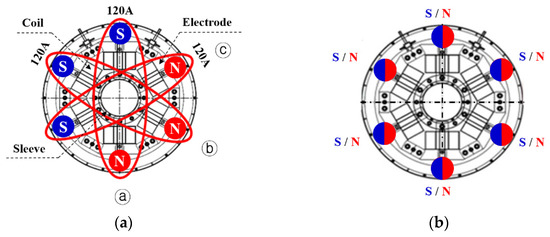
Figure 1.
Schematic diagram of the six-pole electromagnet: (a) DC, (b) AC.
2.2. A356 Alloy
The A356 alloy, an Al-Si-based aluminum alloy with excellent fluidity, can fill molten metal in the solid–liquid coexistence region. The mechanical properties can be improved through heat treatment and the alloy is used in parts that require strength and reliability, such as automobile knuckles, arms, and housing. In particular, the mechanical properties of A356 are related to the size of the aluminum particles, secondary dendrite arm spacing (SDAS), and distribution of Si particles in the process [15,16]. Thus, improving the mechanical properties requires a grain control method for the material, a semi-solid process, and thermal treatment conditions. The change in the solid fraction with temperature can be predicted using Equation (1) [17]. In this study, JMatPro® was used to calculate the solid fraction of the A356 alloy. Figure 2 shows the solid fraction according to the temperature of this alloy. Based on this table, the liquidus line and solidus line temperatures of the A356 alloy were 617 and 553 °C, respectively, whereas the solidification temperature was approximately 64 °C. The temperature for a solid fraction of 20% is 610 °C, and the temperatures for solid fractions of 30 and 40% are 600 and 588 °C, respectively. In this study, A356 alloy was used. The 0.12 wt.% of Ti and a small amount of Sr were added to affect the size of microstructure and roundness. Detailed chemical composition is shown in Table 1.
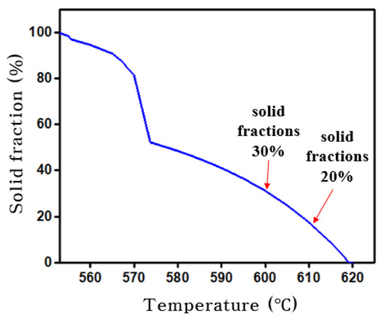
Figure 2.
Solid fraction vs. temperature for A356.

Table 1.
Chemical compositions (wt %) and thermal characteristics of A356.
Here, is the melting temperature of the pure metal, is the eutectic temperature of the binary alloy, and is the distribution coefficient.
3. Experiment
3.1. Current Input Method for A356 Alloy
In this study, the main parameters of the EMS method that were varied were the solid fraction and the method used for current input. Figure 1a shows the DC-type electromagnetic stirrer, comprising three symmetrical pairs of poles with the N and S poles facing each other, and six electromagnets inserted. In order to simultaneously input the current to the symmetrical pole, the current was input in the order of ⓐ→ⓑ→ⓒ. Each electromagnet was set to flow at 120 A. Figure 1b shows the AC-type electromagnetic stirrer, of which the N and S poles change according to the frequency, which was set to 45/55 Hz.
Figure 3 shows a schematic view of the electromagnetic stirrer and the process used to measure the temperature and manufacture a tensile specimen. The process is controlled by changing the method whereby current is supplied to the six-pole electromagnet. Electronic stirring is initiated by the rapid injection of the molten aluminum metal from the heating furnace into the sleeve using a ladle. Simultaneously, as shown in Figure 3a, a thermocouple is inserted into the center of the compartment containing the molten metal to measure the temperature. In the experiments, the temperature of the molten metal in the heating furnace was 700 °C, and that of the molten metal injected into the sleeve was 670 °C. The current input method was set to DC and AC. Once the aluminum material solidified to the desired solid fraction, electronic stirring was discontinued, and the tensile specimen was injected. The manufactured tensile specimens were removed from the stirrer and immediately cooled in water. Figure 3b shows the injection process of the tensile specimen, die, and the shape of the injection product. Two tensile specimens were manufactured in a cavity. Table 2 lists the experimental conditions under which the tensile specimens were manufactured according to the solid fraction and the current input method. The experimental conditions include two current input methods and four different solid fractions, a total of eight conditions that were compared. The solid fractions were 10% (614 °C), 20% (610 °C), 30% (600 °C), and 40% (588 °C). Conditions 1–4 (Table 2) were implemented by setting the current input method to DC, whereas for Conditions 5–8 the current input method was set to AC. A tensile test was conducted to analyze the mechanical properties of the prepared tensile specimens. Figure 4 shows the specifications of the tensile specimens, which were manufactured according to the ASTM E8M standard with a gauge length of 45 mm and a diameter of 9 mm.
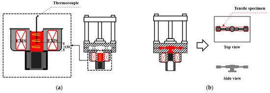
Figure 3.
Process of rheocasting using EMS: (a) Stirring, (b) Injection.
Table 2.
Experiment conditions in EMS process.
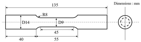
Figure 4.
Specimen geometry (ASTM E8M).
The size and roundness of the solid particles were measured after analyzing the microstructure of the molten metal using an Olympus optical microscope (OLYMPUS BX51M). The equivalent diameter and roundness of the solid particles were defined using Equations (2) and (3) by measuring the area and edge length of each individual solid particle and by taking the average value. The equivalent diameter of the particles is defined by Equation (2), whereas the roundness R, which indicates the spheroidization degree and represents the similarity between the particle and a circle, is expressed by Equation (3). For a completely spherical shape, the roundness is 1, and the value of R increases as the irregularity of the particle increases.
Here, and are the area and perimeter of the particle, respectively.
3.2. Manufacturing for Two-Cavity Lower Arm
After establishing the optimal conditions in the 5 kg molten metal, a two-cavity lower arm was manufactured with the 16kg molten metal. The lower arm, which is an automobile component was manufactured using EMS. The lower arm was manufactured under the experimental conditions of 45/55 Hz with solid fraction of 20% and the current input method set to AC, as listed in Table 3. After manufacturing, T6 heat treatment was conducted on the lower arm. A tensile test was conducted to evaluate the mechanical properties, such as tensile, yield strength, and elongation, according to positions. The tensile specimens were manufactured according to the ASTM E8M standard with a gauge length of 45 mm and a diameter of 9 mm.
Table 3.
Experiment conditions for manufacturing a two-cavity lower arm in EMS process.
4. Results and Discussion
Figure 5 shows the results of evaluating the castability of die-cast products while changing the solid fraction from 10 to 40%. The solid fraction of 10% presented scattering, indicating that the formability was not satisfactory as shown in Figure 5a. In contrast, the solid fractions of 20 and 30% did not result in scattering and the injection was satisfactory. The molten metal with a solid fraction of 40% solidified in the sleeve, resulting in an incomplete shape as a result of a poor injection as shown in Figure 5d. Judging the appearance and castability of the casting revealed that the optimal conditions for EMS die-casting were to inject molten metal at temperatures of approximately 610 and 600 °C, with solid fractions of 20 and 30%, respectively.
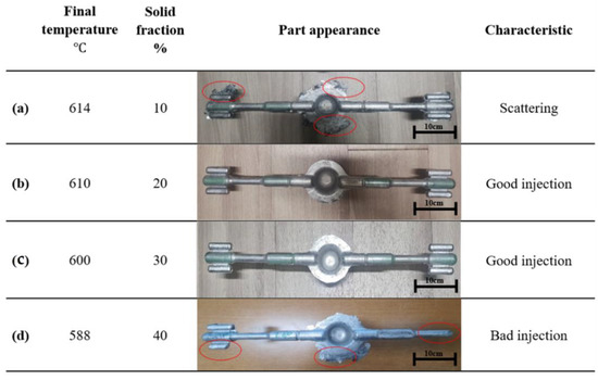
Figure 5.
Castability according to solid fraction: (a) T = 614 °C, = 10%, (b) T = 610 °C, = 20%, (c) T = 600 °C, = 30%, (d) T = 600 °C, = 40%.
Figure 6 shows the mechanical properties of the tensile specimen manufactured using EMS according to the solid fraction and the current input method as a stress–strain curve. In the case of the specimen with a solid fraction of 20% manufactured at 610 °C using a DC input, the ultimate tensile strength was 147 MPa and the elongation was 9.2%. At 600 °C, with a solid fraction of 30%, the tensile strength was 136 MPa, and the elongation was 9.7%. In the case of specimens manufactured using an AC input, the tensile strength was the highest at 177 MPa at 610 °C with a solid fraction of 20%, whereas the tensile strength was 164 MPa at 600 °C with a solid fraction of 30%. The corresponding elongation was 8.5 and 8.7%, respectively. This experiment confirmed that the strength at 610 °C with a solid fraction of 20% was higher than that at 600 °C with a solid fraction of 30%, and that the specimen strength was superior with the AC input method. The elongation of the tensile specimens under the four conditions was 8 to 9%, which was insignificant.
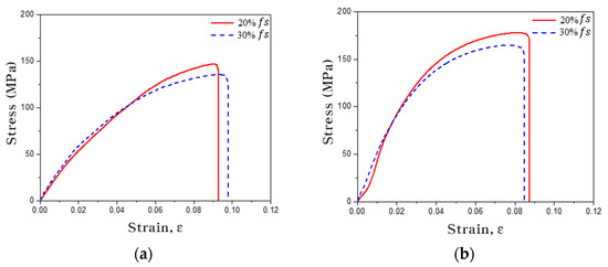
Figure 6.
Stress–strain curve according to current input method: (a) DC, (b) AC.
Figure 7 compares the mechanical properties of the tensile specimens in the form of a bar graph. As shown in the figure, the tensile strength improved by 20% when using an AC, rather than a DC, as the current input method. Apart from this, a solid fraction of 20% improved the tensile strength by 8% compared to a solid fraction of 30%. The elongation decreased by 0.5 to 1.2% when using an AC compared to a DC.
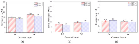
Figure 7.
Mechanical properties according to the current input method and solid fraction: (a) ultimate tensile strength, (b) yield strength, and (c) elongation.
Figure 8 shows the microstructure at the different positions on each tensile specimen according to the current input method and solid fraction. The images were taken with the optical microscope. Figure 8a shows the microstructure of the tensile specimen according to the current input method when the solid fraction was 20%. In the case of the DC input, as shown for positions 1 and 3, marked in red, the solid particles of A356 are coarse, and irregular solid particles are combined to form a dendritic structure. On the other hand, the solid particles of A356 obtained via the AC input are finer and are spherically shaped. Although irregular particles were observed, they did not form dendritic structures. Figure 8b shows the microstructure according to the current input method at a solid fraction of 30%. For the DC input method and a solid fraction of 30%, irregular solid particles and dendritic structures were formed at positions 1, 2, and 3, marked in red. However, the microstructure obtained using the AC input method did not contain dendritic structures and the A356 particles were fine and spherical in shape.
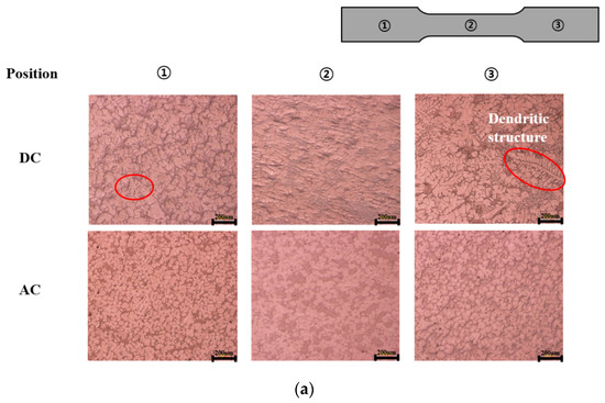
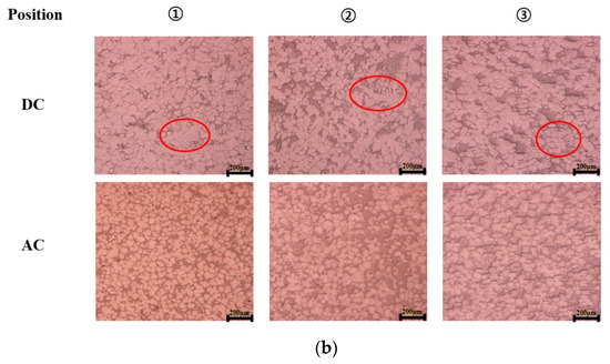
Figure 8.
Optical micrographs showing the microstructure of A356 according to the current input method: (a) 20% , (b) 30% .
Figure 9 shows the equivalent diameter and roundness of solid particles measured at different locations on the tensile specimen according to the solid fraction and current input method. Overall, particles formed with the AC input method were smaller and more spherical compared to the DC method. Specifically, the equivalent diameter and roundness of the solid particles prepared using the AC input method at a solid fraction of 20% had the smallest equivalent diameter and the most optimal roundness. With the DC input method, for a solid fraction of 30%, the equivalent particle diameters at positions 1 to 3 were 93, 95, and 100 μm, and the roundness was 7.2, 8.1, and 8.3. In comparison, the equivalent diameters with the AC input method were 53, 60, and 62 μm, and the roundness was 1.8, 1.8, and 1.9. The equivalent diameter and roundness of the solid particles increase at positions closer to the gate.
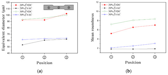
Figure 9.
(a) equivalent diameter and (b) roundness of particles of A356.
Figure 10 shows the mechanical properties, such as the tensile, yield stress, and elongation, of the manufactured two-cavity lower arm according to the positions in a bar graph. In the case before the heat treatment, the tensile strength and elongation were 212 MPa and 12.1% at position 1, respectively. The tensile strength was more than 200 MPa at all positions. After the T6 heat treatment, the highest tensile strength and elongation were 296 MPa and 7.8% at position 1. After the T6 treatment, the tensile strength increased by 39% compared to the specimen before the T6 treatment. In addition, the results comparing the tensile strength data described in the literature were similar [16,18,19].
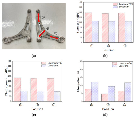
Figure 10.
Mechanical properties of two-cavity lower arm at each position: (a) lower arm, (b) ultimate tensile strength, (c) yield strength, and (d) elongation.
5. Conclusions
In this study, the mechanical properties and microstructural changes induced by electromagnetic stirring were analyzed according to the solid fraction and current input methods. Specimens were die-casted using a large electromagnetic stirrer featuring an electromagnet with outer and inner diameters of 600 and 145 mm, respectively, and a height of 260 mm. The following experimental results were obtained:
- Using EMS for die-casting, it was confirmed that the optimal melting temperature of products with good castability with a solid fraction of 20–30% was 600–610 °C.
- The mechanical properties were superior when an AC was used as the current input method: the tensile strength and elongation were 177 MPa and 8.7%, respectively, compared to 147 MPa and 9.2% when the input method was a DC, confirming that the tensile strength was improved by 20%.
- The tensile strength of the material containing a solid fraction of 20% was 8% higher compared to that of the material with a solid fraction of 30%. In terms of the equivalent diameter and roundness, those of the material with a solid fraction of 20% prepared with an AC yielded the most optimal results.
- The manufactured lower arm made of 16kg molten metal under the optimal conditions at 5 kg showed good mechanical properties depending on the positions and showed 39% higher tensile strength through the T6 heat treatment.
Author Contributions
Investigation, writing—original draft, W.-J.L.; experiment, J.-P.-S.-S.B.; funding acquisition, formal analysis, C.-G.K.; validation, supervising, writing—review and editing, M.-S.L. All authors have read and agreed to the published version of the manuscript.
Funding
This research was supported by the Basic Science Research Program through the National Research Foundation of Korea (NRF) funded by the Ministry of Science, ICT & Future Planning (No. 2021R1C1C2012763), the World Class 300 Project R&D (No. S2640396) of the MOTIE, and the MSS (Korea) and Korea Basic Science Institute (National research Facilities and Equipment Center) grant funded by the Ministry of Education. (No. 2021R1A6C101A449).
Data Availability Statement
The data presented in this study are available in this article.
Conflicts of Interest
The authors declare no conflict of interest.
References
- Kaplan, Y.; Tan, E.; Ada, H.; Aksöz, S. Comparison of the effects of B4C and SiC reinforcement in Al-Si matrix alloys produced via PM method. In Light Metals; Springer: Berlin/Heidelberg, Germany, 2019; pp. 129–134. [Google Scholar]
- Patel, J.B.; Liu, Y.Q.; Shao, G.; Fan, Z. Rheo-processing of an alloy specifically designed for semi-solid metal processing based on the Al–Mg–Si system. Mater. Sci. Eng. A 2008, 479, 341–349. [Google Scholar] [CrossRef]
- Hirsch, J. Recent development in aluminium for automotive applications. Trans. Nonferrous Met. Soc. China 2014, 24, 1995–2002. [Google Scholar] [CrossRef]
- Kim, H.H.; Lee, M.S.; Kang, C.G. Reduction in liquid segregation and microstructure improvement in a semisolid die casting process by varying injection velocity. Metall. Mater. Trans. B 2011, 42, 156–170. [Google Scholar] [CrossRef]
- Pola, A.; Tocci, M.; Kapranos, P. Microstructure and Properties of Semi-Solid Aluminum Alloys: A Literature Review. Metals 2018, 8, 181. [Google Scholar] [CrossRef]
- Kapranos, P. Current state of semi-solid net-shape die casting. Metals 2019, 9, 1301. [Google Scholar] [CrossRef]
- Irani, S.B.; Z-Hanzaki, A.; Bazaz, B.; Roosraei, A.A. Microstructure evolution and semi-solid deformation behavior of an A356 aluminum alloy processed by strain induced melt activated method. Mater. Des. 2013, 46, 579–587. [Google Scholar] [CrossRef]
- Ko, J.H.; Seo, P.K.; Kang, C.G. A Study on Rheology Forming Process of Al-7%Si Alloy with Electromagnetic Application. Trans. Mater. Processing 2006, 15, 195–205. [Google Scholar]
- Jaberi, F.S.; Cockcroft, S.L.; Maijer, D.M.; Philion, A.B. Comparison of the semi-solid constitutive behaviour of A356 and B206 aluminum foundry alloys. J. Mater. Processing Technol. 2019, 266, 37–45. [Google Scholar] [CrossRef]
- Bae, J.W.; Kim, T.W.; Kang, C.G. Experimental investigation for rheology forming process of Al–7% Si aluminum alloy with electromagnetic system. J. Mater. Processing Technol. 2007, 191, 165–169. [Google Scholar] [CrossRef]
- Kang, C.G.; Jin, C.K.; Bolouri, A. Semisolid forming of thin plates with microscale features. Procedia Eng. 2014, 81, 63–74. [Google Scholar] [CrossRef][Green Version]
- Spencer, D.B.; Mehrabian, R.; Flemings, M.C. Rheological behavior of Sn-15 pct Pb in the crystallization range. Metall. Mater. Trans. B 1972, 3, 1925–1932. [Google Scholar] [CrossRef]
- Kang, C.G.; Bae, J.W.; Kim, B.M. The grain size control of A356 aluminum alloy by horizontal electromagnetic stirring for rheology forging. J. Mater. Processing Technol. 2007, 187, 344–348. [Google Scholar] [CrossRef]
- Zoqui, E.J.; Paes, M.; Sadipi, E.E. Macro- and microstructure analysis of SSM A356 produced by electromagnetic stirring. J. Mater. Processing Technol. 2002, 120, 365–373. [Google Scholar] [CrossRef]
- Tsai, Y.C.; Chou, C.Y.; Lee, S.L.; Lin, C.K.; Lin, J.C.; Lim, S.W. Effect of trace La addition on the microstructures and mechanical properties of A356 (Al–7Si–0.35Mg) aluminum alloys. J. Alloy. Compd. 2009, 487, 157–162. [Google Scholar] [CrossRef]
- Park, C.; Kim, S.S.; Kwon, Y.N.; Lee, Y.S.; Lee, J.H. Mechanical and corrosion properties of rheocast and low-pressure cast A356-T6 alloy. Mater. Sci. Eng. A 2005, 391, 86–94. [Google Scholar] [CrossRef]
- Kurz, W.; Fisher, D.J. Fundamentals of Solidification; CRC Press: Boca Raton, FL, USA, 1984. [Google Scholar]
- Lee, M.S.; Kang, C.G. Comparative study of direct and indirect forging processes for rheological material of A356 aluminium alloy. Mater. Sci. Technol. 2011, 27, 406–415. [Google Scholar] [CrossRef]
- Kim, H.H.; Kang, C.G. Vacuum-assisted rheo-forging process of A356 aluminum alloys. Int. J. Mach. Tools Manuf. 2008, 48, 1626–1636. [Google Scholar] [CrossRef]


Publisher’s Note: MDPI stays neutral with regard to jurisdictional claims in published maps and institutional affiliations. |
© 2022 by the authors. Licensee MDPI, Basel, Switzerland. This article is an open access article distributed under the terms and conditions of the Creative Commons Attribution (CC BY) license (https://creativecommons.org/licenses/by/4.0/).