Article

Wear-Resistant Fe6AlCoCrNi Medium-Entropy Alloy Coating Made by Laser Cladding

1
Department of Materials Engineering, College of Engineering, Nanjing Agricultural University, Nanjing 210095, China
2
Key Laboratory of Metallurgical Emission Reduction and Resources Recycling of Ministry of Education, Anhui University of Technology, Ma’anshan 243002, China
3
Department of Chemical and Materials Engineering, University of Alberta, Edmonton, AB T6G2H5, Canada
*
Author to whom correspondence should be addressed.
Metals 2022, 12(10), 1686; https://doi.org/10.3390/met12101686
Submission received: 8 September 2022 / Revised: 28 September 2022 / Accepted: 7 October 2022 / Published: 9 October 2022
(This article belongs to the Special Issue Wear and Corrosion Behavior of High-Entropy Alloy)

Abstract

:
An Fe6AlCoCrNi medium-entropy (MEA) coating was coated on a steel substrate by laser cladding. The micro-structure, crystal structure, phases, and wear properties of the coating were investigated. The coating was mainly composed of a dendritic face-center cubic (FCC) phase, which showed preferred crystal orientation of <2 0 0>, normal to the coating surface, and a body-center cubic (BCC) phase. The MEA coating exhibited satisfactory rigidity with superior wear resistance at different loads and temperatures, much higher than that of the steel substrate. When the test temperature increased from 293 K to 573 K, the coefficient of friction (COF) of the coating markedly decreased from about 0.75 to 0.35; a large decrease in wear was also observed. The wear mechanism of the MEA coating was abrasion wear at room temperature, while the wear of the coating at high temperatures involved considerable oxidation, which enhanced the wear resistance of the coating.

1. Introduction

In order to prolong the service life of work pieces made of ferrous materials, coatings with different compositions and structures are used to protect them from surface failure. Alloys and composites with excellent heat resistance, wear resistance, and corrosion resistance are used to make protective coatings on iron and steel. High-entropy alloy (HEA), a non-conventional type of alloy proposed by Yeh et al. [1] and Cantor et al. [2] exhibits many attractive properties and has the potential to be utilized as a protective coating for structure materials such as steel. HEA is designed based on the concept of multi-principle elements and high configuration entropy. HEAs exhibit superior mechanical, high-temperature, and anti-corrosion properties and high flexibility for modification. For this reason, they have attracted a great deal of attention in recent decades for use as effective coatings [3,4,5,6,7,8]. When hard HEA, which combines high hardness, high toughness, and high corrosion resistance, is used in the form of a coating, it can protect the substrate more effectively from wear. Moreover, HEAs contain passive elements (e.g., Cr, Al, Ti), which make the coating highly resistant to aggressive environments. The formed protective oxide film or scale is beneficial to the wear resistance. However, multi-element HEAs may contain rare and expensive metal elements such as Ta, Nb, Mo, Ti [7,8,9,10] and elements that are more expensive than iron, e.g., Co, Cr and Ni, making HEAs relatively costly [3,5,7], thus limiting their applications. Therefore, the application of HEAs in the form of coatings rather than as bulk material certainly helps reduce the cost, while providing the desired wear resistance for surface protection.
In this regard, alloy design is no longer limited to high-entropy alloys (configuration entropy ΔSmix > 1.5 R) but has extended to medium-entropy alloys [11] with an ΔSmix of 1.0–1.5 R. Some medium-entropy alloys (MEA) even having one main element accounting for approximately 50–70% of the alloy’s composition and the resultant structures can maintain one or two solid solution phases [12,13]. Some other MEAs contain less metal elements but the atomic contents of the elements are close [14,15]. Medium-entropy alloys with less micro-structural complications also show comparable or even better performance, compared with high-entropy alloys, against material failure.
Based on the above information and discussion, in this research, a medium-entropy alloy coating was designed and fabricated. The nominal composition of the coating was Fe6AlCoCrNi, derived from equiatomic AlCoCrFeNi high-entropy alloy, which has excellent mechanical properties [5,16,17] with a reduced cost due to its high Fe content. The high-Fe medium-entropy alloy coating is more economical for larger-scale applications, because of its higher UTS/price ratio compared with other MEAs and HEAs. Another reason for choosing this MEA is the greater similarity in the composition of the coating and the steel substrate, which may lead to a smaller mismatch between their heat-expansion coefficients, thus reducing the internal stress for enhanced bonding between the coating and substrate.
The coating was prepared on a steel plate using a well-established technique: laser cladding (LC). In recent decades, various methods, such as electroless plating, electroplating, magnetron sputtering, thermal spraying, and laser metal deposition, etc., were developed to make metal coatings or thin films. Compared with other processes, laser cladding has unique features. It has a higher efficiency [17] than sputtering or plating and thicker coatings can be made within a short time. Moreover, LC coating chemically bonds with the substate instead of relying on physical adhesion, which exists in plating or spraying coating [17,18]. Coaxial powder feeding LC can even be developed to manufacture conformal coatings [18]. Laser cladding is also the basis of newly developed hybrid manufacturing, which combines laser metal deposition (LMD) and milling [19]. The elaborate programming, the scanning strategy, and the controllable processing parameters are particularly important during manufacturing [19]. Laser cladding is known as a typical non-equilibrium process because of its rapid heating and cooling rates, which lead to a significant difference in solidification behavior [4,17,20]. Thus, it is of particular interest to investigate the MEA coating fabricated by laser cladding after the optimization of the processing parameters. The micro-structure and wear properties of the coating were characterized and evaluated. Efforts were made to correlate the micro-structure features with properties of the MEA coating for further developments.

2. Materials and Methods

2.1. Preparation of the MEA Coating

After polishing with 1000-mesh sandpaper, a commercial 45 steel plate (400 mm × 150 mm × 4 mm) was used as the substrate. The substrate was ultrasonically cleaned using anhydrous ethanol and dried using a pressed air flow before laser cladding. Pure Fe, Co, Cr, Ni, and Al powders (size of 48 μm, purity > 99.95%) were used as the raw material for the coating. The metal powders were weighed and mixed with an equiatomic ratio in a planetary ball mill for 2 h; then, they were pre-set on the substrate to form a layer of 0.3 mm in thickness. An LWS-1000 laser processing system (Riton Laser Technology Co. Ltd., Guangzhou, China) was used for multi-channel cladding. During the coating process, high-purity argon (99.9%) was used as the protective gas and was continuously supplied at a speed of 10 L/min. The processing parameters of cladding, which were optimized during the preliminary experiments, are given in Table 1. A number of samples were prepared under the same conditions for different tests.
In general, during laser cladding, the surface of the substrate more or less melts, leading to compositional deviation from the nominal one. In the present case, a large amount of Fe dissolved from the steel substrate into the molten pool. According to results of previous experiments [18] and the atomic ratio of the mixed powders, the fabricated coating has a composition of Fe6CoCrNiAl. Based on the formula of ΔSmix (Equation (1)), the alloy system of the coating has a ΔSmix of 1.227 R (see Equation (2)). Thus, the coating is a medium-entropy alloy coating.
Δ S mix = R i = 1 n c i × l n c i
where R is a gas constant, ci is the molar ratio of the principal element, and n is the number of mixing elements.
Δ S mix = R ( 6 10 l n 6 10 + 1 10 l n 1 10 + 1 10 l n 1 10 + 1 10 l n 1 10 + 1 10 l n 1 10 ) = 1.227 R
Other coatings with different components and prepared by a variety of processing parameters were also tested during the preliminary experiments by the authors. After a preliminary evaluation and screening in terms of performance and formability, the Fe6CoCrNiAl MEA coating was chosen for wear testing and analysis.

2.2. Test Methods

The clad samples were cut vertically along the cladding track using a DK77 wire electrical discharge machine (Suzhou Baoma Numerical Control Equipment Co., Ltd., Suzhou, China). The samples were cold-mounted and polished successively with sandpaper (280, 400, 600, 1000, and 2000 mesh) using a MP-2A polishing machine (Shanghai Metallurgical Equipment Company Ltd., Shanghai, China). They were finally polished to mirror finishing using diamond abrasion paste with a grain size of 0.5 µm. The samples were than etched with aqua regia for 20s to observe their metallographic structures. A FEI-FEG quanta 250 scanning electron microscope (SEM) (Thermo Fisher Scientific Inc., Waltham, MA, USA) and a ZeGage 3D optical profiler (Zygo, Middlefield, CT, USA) were used to observe the cross-section of the coatings and the microscopic morphology of the wear track. The SEM was equipped with an energy-dispersive X-ray spectrometer (EDS), which was used to analyze the chemical composition of selected areas with representative micro-structural features. A PANAlytical X’Pert Powder X-ray diffractometer (XRD) (Malvern Panalytical Ltd., Malvern, UK) was used for phase analysis with the following details: Cu Kα X-ray source, an acceleration voltage of 40 kV, a current of 40 mA, a scanning range of 20–100°, and a scanning step of 0.02°/min.
The micro-hardness of the coating and substrate was measured using a DURAMIN-40A1 automatic micro-hardness instrument (Struers ApS, Ballerup, Denmark) with a load of 0.98 N and a force-holding time of 10 s. Friction and wear experiments were performed using a pin-on-disc wear tester (CSEM Instruments, Neuchatel, Switzerland). A silicon nitride ball with a diameter of 3 mm was used as a pin to abrade surface of the coating. The diameter of the circular wear tracks was 2 mm and the sliding speed was 10 mm/s. The coating samples were tested under the dry sliding condition for 20 min over a total sliding distance of 12 m. An air flow was used to keep the temperature stable. The tests were performed under loads of 1N, 5N, and 10 N at room temperature (293 K), respectively, and then the tests were repeated under a load of 10N at 373 K and 573 K, respectively. A commercial 45 steel plate was also tested under the same conditions as the reference material. Corresponding friction coefficient curves under different testing conditions were recorded. The average widths of wear tracks and wear volumes were measured using a ZeGage 3D optical profiler (Zygo, Middlefield, CT, USA).

3. Results

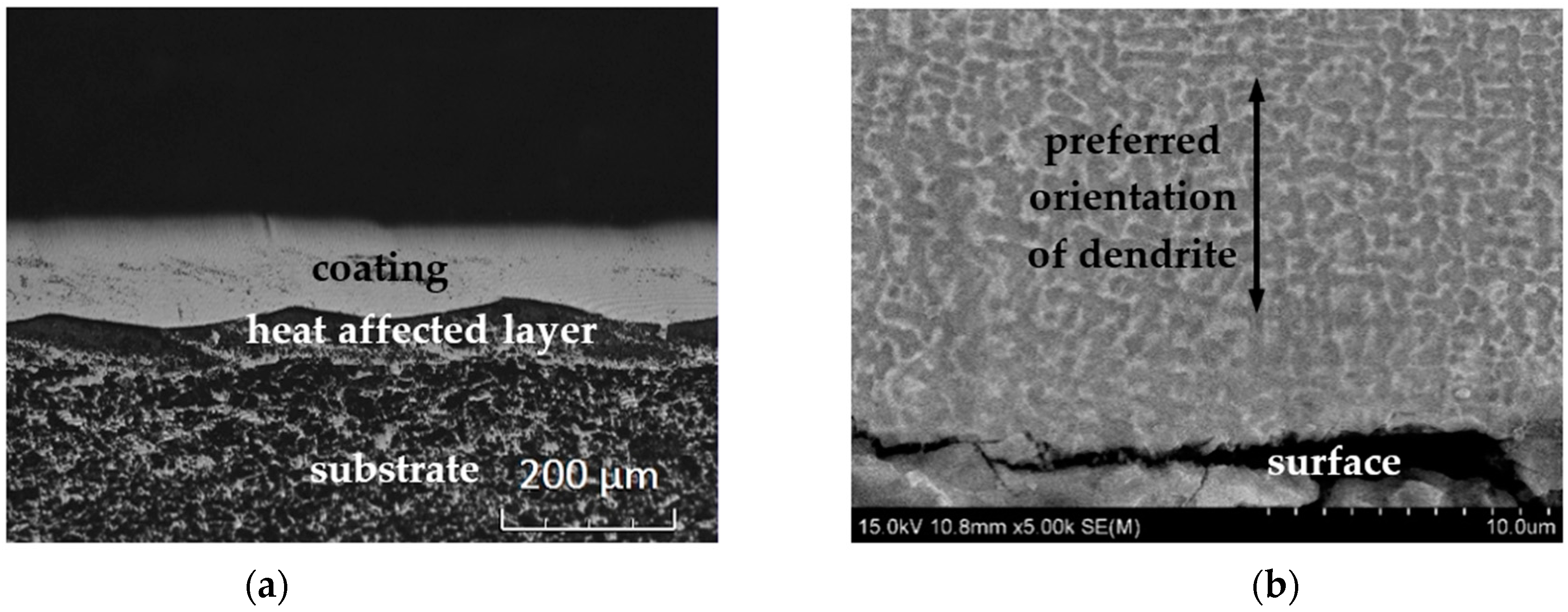
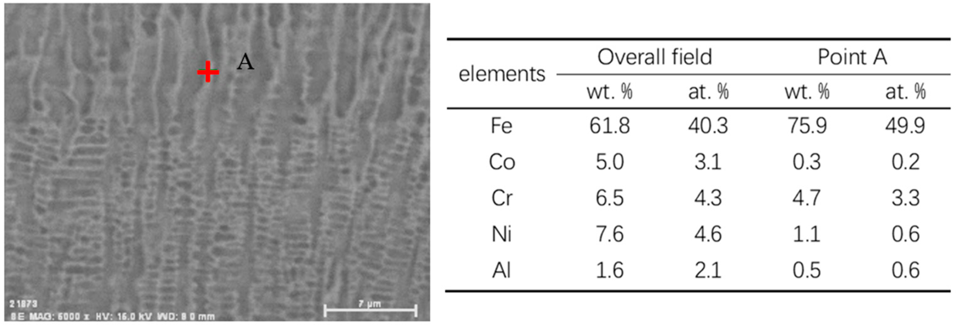
3.1. Morphology, Metallographic Structure, and Phase Composition
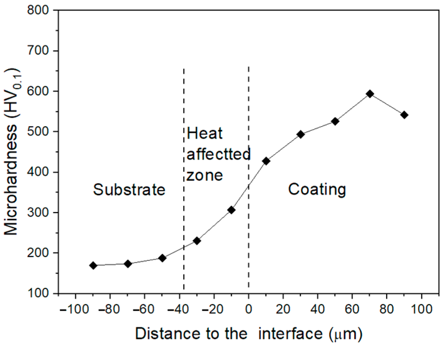
Figure 1 shows the cross-section of the Fe6CoCrNiAl coating. As Figure 1a illustrates, the coating was continuous and flat. The interface between the coating and heat-affected layer clearly exhibited the shape of the molten pool. The coating thickness was in the range of 90–130 μm and the thickness of heat-affected layer was about 50 μm. There were no large pores or cracks present in the coating.
The deep-etched coating exhibited dendrite, which consisted of a dark phase and a brighter phase between dendrites, as shown in Figure 1b. The dendrites showed a tendency of growing perpendicular to the surface because of the vertical temperature gradient. The crystals were nucleated at the interface and then developed along the vertical direction.
In order to identify the phases, X-ray diffraction patterns of the Fe6CoCrNiAl coating and the 45 steel were obtained and are illustrated in Figure 2. The steel substrate showed a main phase of α-Fe. While the coating had a few phases, i.e., a BCC1, BCC2, and FCC phase. The BCC1 phase is a disordered solid solution with a α-Fe crystal structure [6,19]. The BCC2 phase is an ordered BCC solid solution with a smaller lattice constant. The FCC phase is a solid solution that also appeared in the high-entropy alloy [12,13,17,20]. The highest diffraction peak of the FCC phase at 2θ ≈ 43° did not come from the crystal plane (1 1 1) but from the (2 0 0) plane at 2θ ≈ 51°, suggesting that the coating was (2 0 0) textured.
Based on the above-described micro-structure of the coating, the dark dendrite in Figure 1b is thought to be the FCC phase. The growth direction of the dendrites was along <2 0 0> and was vertical to the coating surface. The brighter phase in Figure 1b is a BCC phase, which is a mixture of BCC1 and BCC2. The EDS analysis was conducted to determine the chemical composition of each phase. Figure 3 shows the EDS results of the overall field and the brighter phase. As indicated, the brighter phase (point A), the BCC phase mainly contained Fe with a trace of Cr. Thus, the other elements, such as Co, Ni, Al, are thought to be mainly distributed in the FCC dendrite.
During solidification, the primary FCC dendrites formed and the remaining melt transformed into the BCC phase, which went through spinodal decomposition, forming BCC1 and BCC2 phases. Spinodal decomposition is the spontaneous upward diffusion of solute atoms in a solid state. This transition was observed and proved in multi-element alloys, especially in high-entropy alloys [6,16,21,22,23]. In the present case, BCC1 was mainly composed of Fe and Cr, while other elements were enriched in BCC2. The two nano-scale BCC phases had no clear boundary and could be differentiated even in the SEM image. However, the nano-scale BCC1 and BCC2 phases from the spinodal decomposition could be distinguished under HRTEM [24].

3.2. Hardness

The micro-hardness of the Fe6CoCrNiAl coating was determined by performing measurements from the substrate to the coating on the cross-section. The obtained HV0.1 values are given in Figure 4. As shown, the hardness of the 45 steel in the zone far from the interface was 170 HV0.1 and the heat affected zone next to the interface was lifted to the range of 200–300 HV0.1. The highest coating hardness was 594 HV0.1 and the hardness near coating surface was 542 HV0.1. Generally, the coating rigidity was more than three times that of the substrate.
The high hardness of the MEA coating was mainly attributed to two factors. Firstly, the rapid solidification of the molten pool led to the formation of fine crystals on a sub-micron scale. Secondly, the solid solution, whether in the form of the BCC or FCC structure, greatly differed from the crystal of pure metals, e.g., α-Fe with a BCC structure. In a multi-element system, the solid solutions are composed of several elements with large local lattice distortions, which enhance the effect of pinning dislocations. The 2θ values of the BCC1 diffraction peaks in the XRD pattern of the coating were slightly larger than that of α-Fe (BCC) in the XRD pattern of 45 steel, i.e., the crystal parameters of BCC1 became smaller when other elements dissolved. In general, the distorted crystal lattice of the BCC or FCC phase enhances pinning dislocation, resulting in an increased hardness.
Although the hardness of the coating was not as high as that of the equiatomic high-entropy alloy composed of the same elements, e.g., 887 HV0.5 for the AlCoCrFeNi high entropy alloy reported in [16], it was close to 582 HV, which is the hardness of the AlCoCrFe1.5Ni coating shown in [6], and comparable with that of the AlCoCrFeNi coating (450–550 HV0.5), which was also fabricated by laser cladding [18]. The medium-entropy alloy coating was still able protect the steel surface from wear attack. As shown in many studies [6,16,18,20], the BCC phase in HEA alloy has a higher rigidity than the FCC phase, while the FCC phase has a higher plasticity than the BCC phase, which is beneficial for the coating to prevent internal stress cracks formed during laser cladding. Thus, a proper combination of a rigid BCC phase and softer FCC phase in the form of dendrites may lead to a desired balance between rigidity and plasticity, or a desired combination of hardness and toughness.

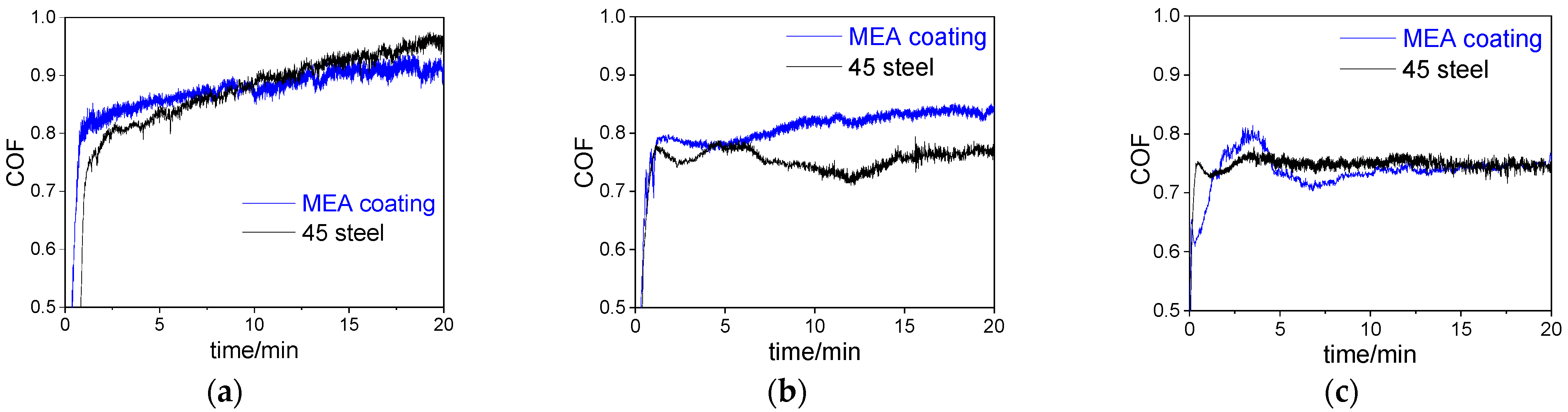
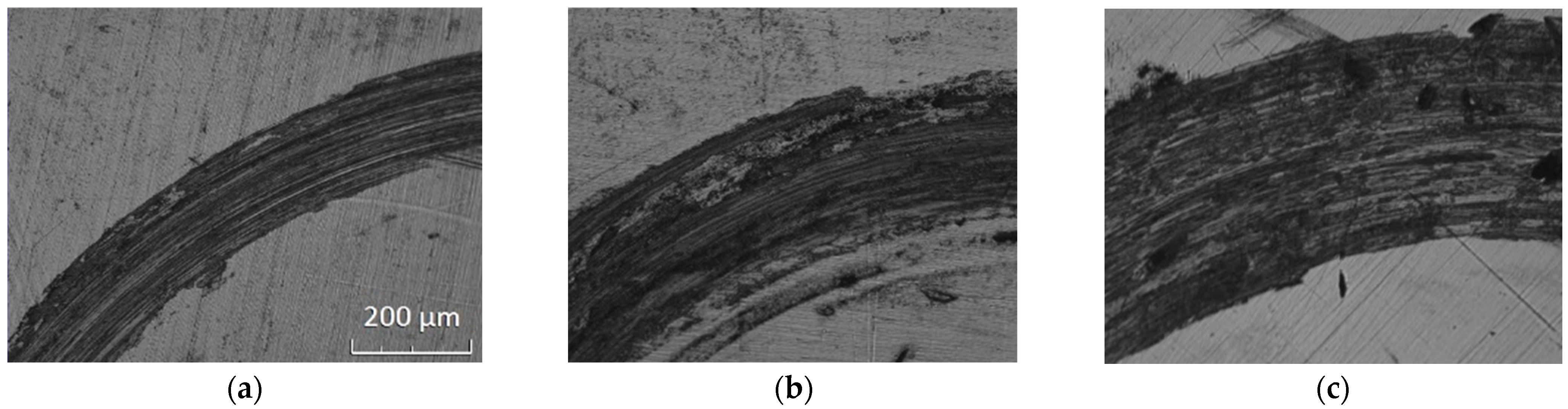
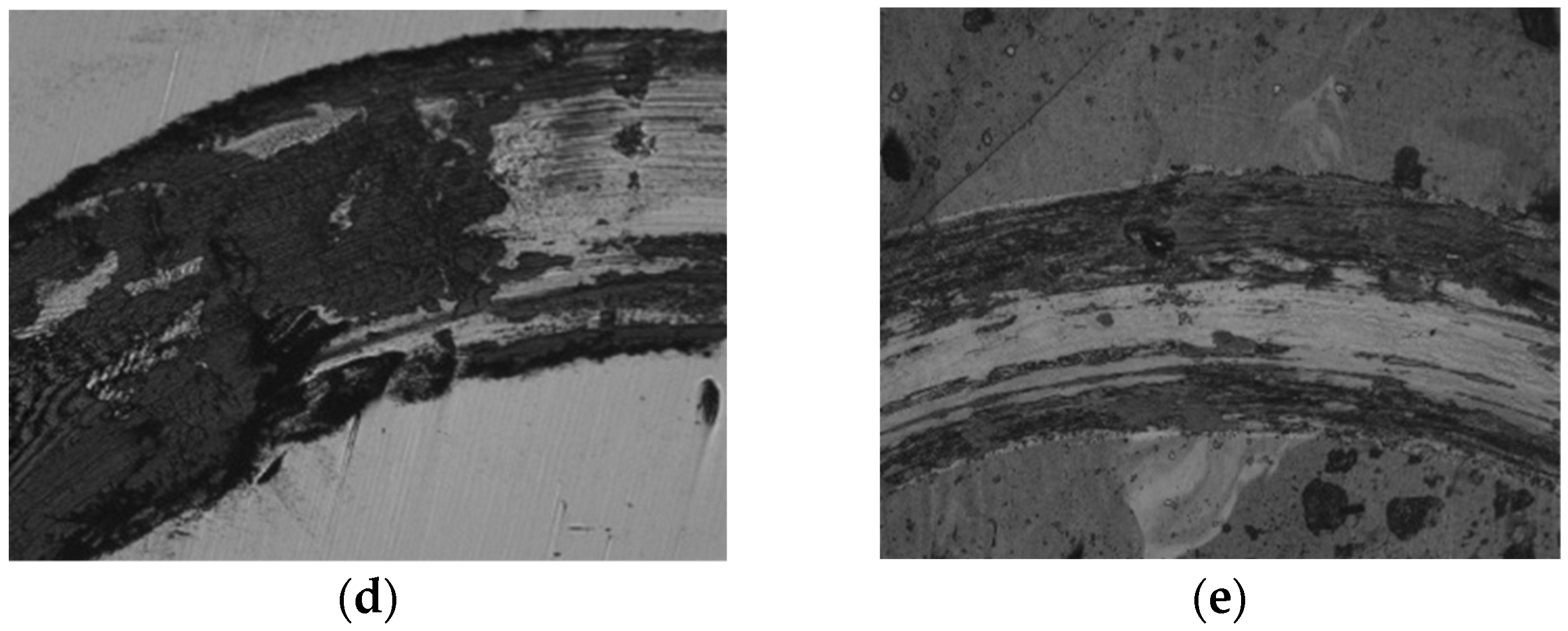
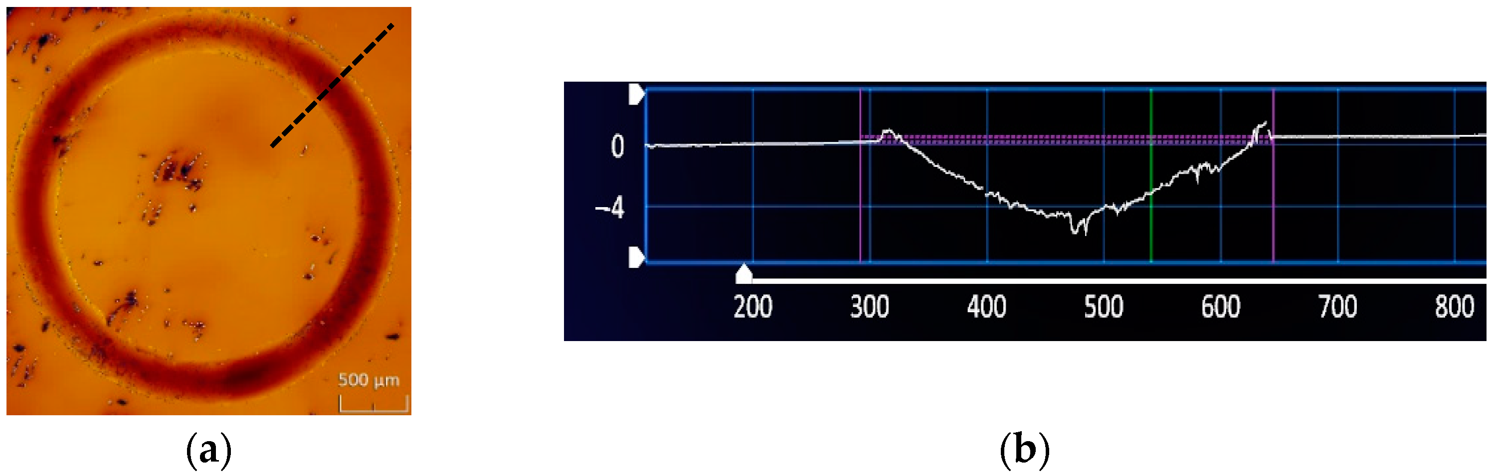
3.3. Friction and Wear Properties

Friction and wear tests were performed under several loads at different temperatures. The determined coefficients of friction (COF) of the coating and the steel substrate under different conditions are listed in Table 2. The average COF values were determined based on the COF-time curves as shown in Figure 5 and Figure 6, respectively. The average COF was obtained by averaging the COF values over the period of 5–20 min.
As shown in Figure 5, the average COF of the MEA coating decreased slightly when the load was increased from 1 N to 10 N. The change in COF of the 45 steel exhibited a similar trend. The coating and the steel had similar COFs. However, the coating had a much lower COF at 573 K, with a COF equal to 0.348, which is less than half its COF at room temperature (RT). However, the steel substrate did not change much within the temperature range.
Volume losses caused by wear during the friction/wear tests were determined. Figure 7 illustrates the morphology of the wear tracks on the Fe6CoCrNiAl coating, showing furrows and grooves (Figure 7a–c). The surface damage to the coating was primarily caused by abrasive wear. Since the counter-part was an Si3N4 ceramic ball with high rigidity, the abrasive particles were the debris falling from the surface of the coating. The width of the wear track increased with increasing load. With an increase in the temperature, the width of wear track slightly decreased. When tested at 575 K, the surface of the sample displayed noticeable oxidation.
Figure 8a illustrates a sample wear track the dimensions of which were determined using a ZeGage 3D optical profiler. The cross-section profile (Figure 8b) was obtained along the radius of the wear track ring which shows as the black dotted line in Figure 8a. The widths and volume losses (V) of the MEA coating and the steel substrate were measured and are shown in Figure 9; the wear rate and its variations with load and temperature are given in Table 3. The wear track width and volume loss exhibited the same trend of changes with respect to the samples (listed in Table 2). The wear rate (W) was calculated using the formula, W = V/SL, where S is the sliding distance and L the load. As shown in Table 3, the wear rate of the steel substrate increased with load and temperature. The wear rate of the MEA coating also increased with load and temperature, but it decreased considerably at 573 K. The drop in volume loss of the MEA coating at 573 K was attributed to the formed oxide scale, which was protective. The corresponding COF of the MEA coating also showed a drop at 573 K, exhibiting a lower average COF value of 0.348, which is less than half the COF determined at RT or 373 K.
As shown in Table 3, the MEA coating had a much higher wear resistance than the 45 steel in all cases. One may see that the wear rate of the MEA coating (WMEAC) was only about 1/14 of the wear rate of the 45 steel (W45).

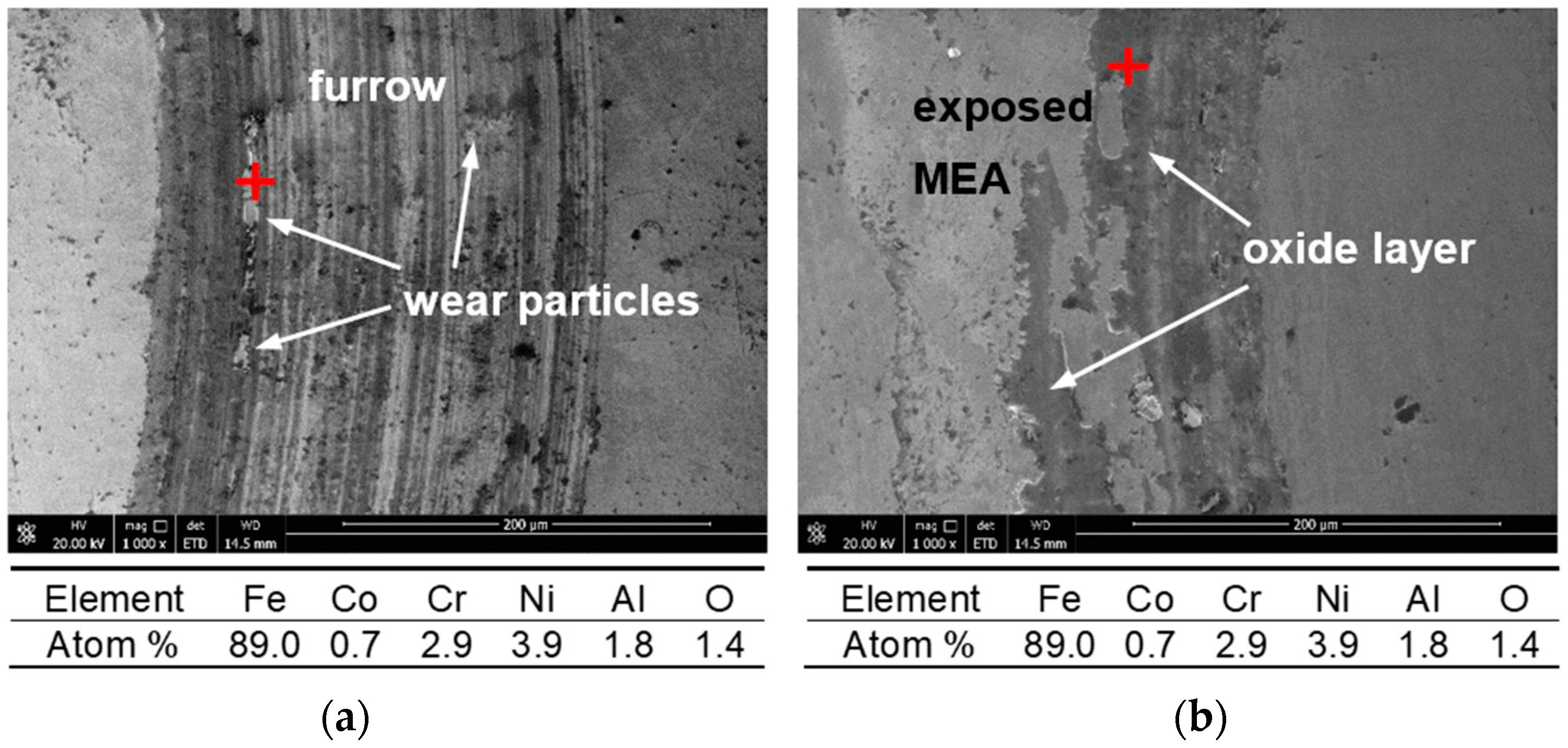
3.4. Further Analysis and Discussion

For further information, the local chemical composition of the debris on the wear track of the MEA coating was analyzed via EDS analysis. The results of the analysis for the MEA coatings in group 3 and 5 are shown in Figure 10. The wear debris in the wear track of coating tested at room temperature and at 10 N, marked by a red “+” in Figure 10a, has a composition similar to that of the MEA coating. However, considerable oxidation occurred on the work surface of the coating tested at 573 K. The zone marked by a red “+” on the coating shown in Figure 10b contained much more oxygen than the coating tested at RT. Considering the presence of the passive elements Cr and Al at high concentrations, the oxide layer is thought to have mainly consisted of aluminum oxide and chromium oxide. The formation energies of aluminum oxide and chromium oxide are low [4]. When the temperature increased, Al and Cr were oxidized prior to other metal elements. α-Al2O3 and Cr2O3 have the same crystal structure, with a space group of R-3c 167. Their lattice constants (α-Al2O3: a = 4.76 Å, c = 12.99 Å; Cr2O3: a = 4.96 Å, c = 13.59 Å) are close, which makes it easy for them to form an oxide solid solution, which is described as Al2−xCrxO3. The oxide formed a dense and compact thin layer, which could prevent further oxidation of the MEA coating.
During wear testing at high temperatures, the COF curve shows an increased fluctuation because of the intermittent localized spalling of the oxide layer. As shown in Figure 7d,e and Figure 10b, there are light and dark areas in the wear tracks. The dark area is covered by oxide, while the bright area is the MEA coating after the oxide scale was peeled off or removed by the wearing force. The oxide adhered on the coating and formed a thin harder layer, leading to a lowered COF, but spallation of the oxide layer resulted in COF fluctuation. Such a phenomenon is often observed [4,8,25]. In contrast, the COF curve of 45 steel is comparatively smooth since the iron oxide was loose and fragile and may continuously fall off from the worn surface during wear testing. The lower hardness of 45 steel increased the contact area, leading to a higher COF and wear rate.

4. Conclusions

A practical Fe6AlCoCrNi medium-entropy alloy coating was made on a steel substrate by laser cladding.
(1)
Analysis of the micro-structure and phases of the MEA coating indicated that the coating was mainly composed of FCC, in dendritic form, and BCC phases. The FCC phase had its preferred (2 0 0) crystal plane parallel to the coating surface.
(2)
At different temperatures and loads, the wear rate of the MEA coating was always much lower than that of the steel substrate. At the maximum testing temperature of 573 K, the coating presented the highest wear resistance, benefiting from the formed oxide scale, with its volume loss being only 1/14 that of the steel substrate.
(3)
The wear mechanism of MEA coating changed from abrasive wear to oxidative wear when the temperature increased from RT to 573 K. At 573 K, the COF of the coating sharply decreased because of the formation of oxide scale containing Al and Cr oxides. The oxide scale effectively reduced the COF and wear.
This study demonstrates that the MEA coating can provide steel with effective protection against wear attack.

Author Contributions

Conceptualization, K.C. and D.L.; methodology, K.C. and M.W.; validation, H.P., M.W. and X.W.; formal analysis, H.P. and M.W.; investigation, H.P. and X.W.; data curation, K.C.; writing—original draft preparation, K.C.; writing—review and editing, D.L.; visualization, K.C.; supervision, D.L. All authors have read and agreed to the published version of the manuscript.

Funding

This research was funded by The China Postdoctoral Science Funding (The China Postdoctoral Science Foundation, grant number 2018M632313) and The Jiangsu Overseas Visiting Scholar Program for University Prominent Young & Middle-Aged Teachers and Presidents.

Institutional Review Board Statement

Not applicable.

Informed Consent Statement

Not applicable.

Data Availability Statement

The data that support the findings of this study are all own results of the authors.

Conflicts of Interest

The authors declare no conflict of interest.

References

  1. Yeh, J.W.; Chen, S.K.; Lin, S.J.; Gan, J.Y.; Chin, T.S.; Shun, T.T.; Tsau, C.H.; Chang, S.Y. Nanostructured High-Entropy Alloys with Multiple Principal Elements: Novel Alloy Design Concepts and Outcomes. Adv. Eng. Mater. 2004, 6, 299–303. [Google Scholar] [CrossRef]
  2. Cantor, B.; Chang, I.T.H.; Knight, P.; Vincent, A.J.B. Microstructural Development in Equiatomic Multicomponent Alloys. Mater. Sci. Eng. A 2004, 375, 213–218. [Google Scholar] [CrossRef]
  3. Yoosefan, F.; Ashraf, A.; Monir Vaghef, S.M. Characterization of Co–Cr–Fe–Mn–Ni High-Entropy Alloy Thin Films Synthesized by Pulse Electrodeposition: Part 2: Effect of Pulse Electrodeposition Parameters on the Wettability and Corrosion Resistance. Met. Mater. Int. 2021, 27, 106–117. [Google Scholar] [CrossRef]
  4. Cui, Y.; Shen, J.; Manladan, S.M.; Geng, K.; Hu, S. Wear Resistance of FeCoCrNiMnAlx High-Entropy Alloy Coatings at High Temperature. Appl. Surf. Sci. 2020, 512, 145736. [Google Scholar] [CrossRef]
  5. Mu, Y.; Zhang, L.; Xu, L.; Prashanth, K.; Zhang, N.; Ma, X.; Jia, Y.; Xu, Y.; Jia, Y.; Wang, G. Frictional Wear and Corrosion Behavior of AlCoCrFeNi High-Entropy Alloy Coatings Synthesized by Atmospheric Plasma Spraying. Entropy 2020, 22, 740. [Google Scholar] [CrossRef]
  6. Zhang, G.J.; Tian, Q.W.; Yin, K.X.; Niu, S.Q.; Wu, M.H.; Wang, W.W.; Wang, Y.N.; Huang, J.C. Effect of Fe on Microstructure and Properties of AlCoCrFexNi (x =1.5, 2.5) High Entropy Alloy Coatings Prepared by Laser Cladding. Intermetallics 2020, 119, 106722. [Google Scholar] [CrossRef]
  7. Wang, W.; Qi, W.; Zhang, X.; Yang, X.; Xie, L.; Li, D.; Xiang, Y. Superior Corrosion Resistance-Dependent Laser Energy Density in (CoCrFeNi)95Nb5 High Entropy Alloy Coating Fabricated by Laser Cladding. Int. J. Miner. Met. Mater. 2021, 28, 888–897. [Google Scholar] [CrossRef]
  8. Fan, J.; Liu, X.; Pu, J.; Shi, Y. Anti-Friction Mechanism of VAlTiCrMo High-Entropy Alloy Coatings Through Tribo-Oxidation Inducing Layered Oxidic Surface. Tribol. Int. 2022, 171, 107523. [Google Scholar] [CrossRef]
  9. Zhang, Y.; Chen, X.; Jayalakshmi, S.; Singh, R.A.; Konovalov, S.; Wang, Y. Replacement of Ta with Equi-Atomic Radius Nb Atoms in CoCrFeNiTa High Entropy Alloys: Effect on Microstructure and Mechanical Properties. Mater. Lett. 2021, 297, 129966. [Google Scholar] [CrossRef]
  10. Kanyane, L.R.; Malatji, N.; Popoola, A.P.I.; Fayomi, O.S.I. Synthesis of Equi-Atomic Ti–Al–Mo–Si–Ni High Entropy Alloy via Spark Plasma Sintering Technique: Evolution of Microstructure, Wear, Corrosion and Oxidation Behaviour. Results Phys. 2019, 14, 102465. [Google Scholar] [CrossRef]
  11. Wang, J.; Wu, Q.; Li, Y.; Wang, Z.; Li, J.; Wang, J. Phase Selection of BCC/B2 Phases for the Improvement of Tensile Behaviors in FeNiCrAl Medium Entropy Alloy. J. Alloys Compd. 2022, 916, 165382. [Google Scholar] [CrossRef]
  12. Bae, J.W.; Kim, H.S. Towards Ferrous Medium-Entropy Alloys with Low-Cost and High-Performance. Scr. Mater. 2020, 186, 169–173. [Google Scholar] [CrossRef]
  13. Song, J.; Chai, Z.; Zheng, J.; Wu, Q.; He, F.; Yang, Z.; Li, J.; Wang, J.; Yang, H.; Wang, Z. Design Fe-based Eutectic Medium-Entropy Alloys Fe2NiCrNbx. Acta Metall. Sin. Engl. Lett. 2021, 34, 1103–1108. [Google Scholar] [CrossRef]
  14. Chen, J.; Xiao, J.; Zhang, L. Interdiffusion Behaviors Between NiCrFe alloy and Low-/Medium-/High-Entropy Alloys. J. Alloys Compd. 2022, 896, 162711. [Google Scholar] [CrossRef]
  15. Xue, B.; Lei, W.; Liu, X.; Chen, S. Effect of Medium Entropy Alloy Powder-Core Wire on Friction Wear and Corrosion Resistance of Arc Cladding Additive Layer. Mater. Res. Express 2020, 7, 076521. [Google Scholar] [CrossRef]
  16. Wu, M.; Chen, K.; Xu, Z.; Li, D.Y. Effect of Ti Addition on the Sliding Wear Behavior of AlCrFeCoNi High-Entropy Alloy. Wear 2020, 462, 203493. [Google Scholar] [CrossRef]
  17. Guo, W.; Ding, N.; Liu, G.; Jing, C.; Xu, H.; Liu, L.; Xu, N.; Wu, X.; He, J.; Zaïri, F. Microstructure Evolution of a Multi-Track AlCoCrFeNi High Entropy Alloy Coating Fabricated by Laser Cladding. Mater. Charact. 2022, 184, 111660. [Google Scholar] [CrossRef]
  18. Zhu, S.; Chen, W.; Zhan, X.; Ding, L.; Wang, E. Optimization of Dilution Rate of Laser Cladding Repair Based on Deep Learning. Int. J. Adv. Manuf. Technol. 2020, 110, 1471–1484. [Google Scholar] [CrossRef]
  19. González-Barrio, H.; Calleja-Ochoa, A.; Norberto López de Lacalle, L.; Lamikiz, A. Hybrid manufacturing of complex components: Full methodology including laser metal deposition (LMD) module development, cladding geometry estimation and case study validation. Mech. Syst. Signal Process. 2022, 179, 109337. [Google Scholar] [CrossRef]
  20. Wei, X.; Zhang, P.; Yu, Z.; Yan, H.; Wu, D.; Shi, H.; Chen, J.; Lu, Q.; Tian, Y.; Ma, S.; et al. Effect of Phase Transformation on Mechanical Properties of Al16.80Co20.74Cr20.49Fe21.28Ni20.70 High Entropy Alloy Coatings Processed by Laser Cladding. J. Alloys Compd. 2021, 862, 15856. [Google Scholar] [CrossRef]
  21. Hecht, U.; Gein, S.; Stryzhyboroda, O.; Eshed, E.; Osovski, S. The BCC-FCC Phase Transformation Pathways and Crystal Orientation Relationships in Dual Phase Materials from Al–(Co)–Cr–Fe–Ni Alloys. Front. Mater. 2020, 7, 287. [Google Scholar] [CrossRef]
  22. Liu, X.S.; Li, R.; Lu, Y.; Zhang, Y.F.; Yu, P.F.; Li, G. Spinodal Decomposition Induced Nanoprecipitates Strengthened CoCrNi-Base Medium Entropy Alloy. Mater. Sci. Eng. A 2021, 822, 141674. [Google Scholar] [CrossRef]
  23. Vida, Á.; Lábár, J.; Dankházi, Z.; Maksa, Z.; Molnár, D.; Varga, L.K.; Kalácska, S.; Windisch, M.; Huhn, G.; Chinh, N.Q. A Sequence of Phase Transformations and Phases in NiCoFeCrGa High Entropy Alloy. Materials 2021, 14, 1076. [Google Scholar] [CrossRef]
  24. Sim, R.K.; Xu, Z.; Wu, M.Y.; He, A.; Chen, D.L.; Li, D.Y. Microstructure, mechanical properties, corrosion and wear behavior of high-entropy alloy AlCoCrFeNix (x > 0) and medium-entropy alloy (x = 0). J. Mater. Sci. 2022, 57, 11949. [Google Scholar] [CrossRef]
  25. Feng, K.; Shao, T. The Evolution Mechanism of Tribo-Oxide Layer during High Temperature Dry Sliding Wear for Nickel-Based Superalloy. Wear 2021, 476, 203747. [Google Scholar] [CrossRef]
Figure 1. Cross-sectional views of the fabricated Fe6CoCrNiAl coating: (a) an optical microscope image; (b) a higher magnification image obtained via SEM.
Metals 12 01686 g001
Figure 2. XRD pattern of 45 steel and Fe6CoCrNiAl coating.
Metals 12 01686 g002
Figure 3. EDS analysis of the MEA coating, the overall composition, and the bright phase between dendrites (point A).
Metals 12 01686 g003
Figure 4. Micro-hardness values on the cross-section of the sample from the substrate to the coating.
Metals 12 01686 g004
Figure 5. Friction coefficient curves at different loads (RT): (a) 1 N; (b) 5 N; (c) 10 N.
Metals 12 01686 g005
Figure 6. Friction coefficient curves at different temperatures (10 N): (a) 293 K; (b) 373 K; (c) 573 K.
Metals 12 01686 g006
Figure 7. Wear track of Fe6CoCrNiAl coating: (a) 1 N, RT; (b) 5 N, RT; (c) 10 N, RT; (d) 10 N, 373 K; (e) 10 N, 573 K.
Metals 12 01686 g007aMetals 12 01686 g007b
Figure 8. Characterization method of wear loss: (a) whole wear track; (b) cross-section profile.
Metals 12 01686 g008
Figure 9. Average width of wear track (a), volume loss (b).
Metals 12 01686 g009
Figure 10. EDS analysis for wear tracks of coatings: (a) tested at RT (10 N); (b) tested at 573 K (10 N).
Metals 12 01686 g010
Table 1. Process parameters of laser cladding.
ParametersLaser Power (W)Scan Rate (mm·min−1)Spot Diameter (mm)Overlap RatePreset Layer Thickness (µm)
Value2002400.650%300
Table 2. Friction/wear test parameters and the determined average COF.
Group No.Temperature (K)Load (N)COF of Coating (μ)COF of 45 Steel (μ)
129310.8910.905
229350.8210.753
3293100.7360.749
4373100.7880.795
5573100.3480.735
Table 3. Wear rates of the MEA coating and 45 steel at different loads and temperatures.
Group No.Temperature (°C)Load (N)WMEAC (×10−3 mm3/N·m)W45 (×10−3 mm3/N·m)
12011.0393.948
22052.43918.376
320108.34457.248
41001036.48112.74
5300109.74133.356
Publisher’s Note: MDPI stays neutral with regard to jurisdictional claims in published maps and institutional affiliations.

