
Effect of Roll Material on Strip Solidification between the Rolls of a Vertical-Type High-Speed Twin-Roll Caster
Abstract
:1. Introduction
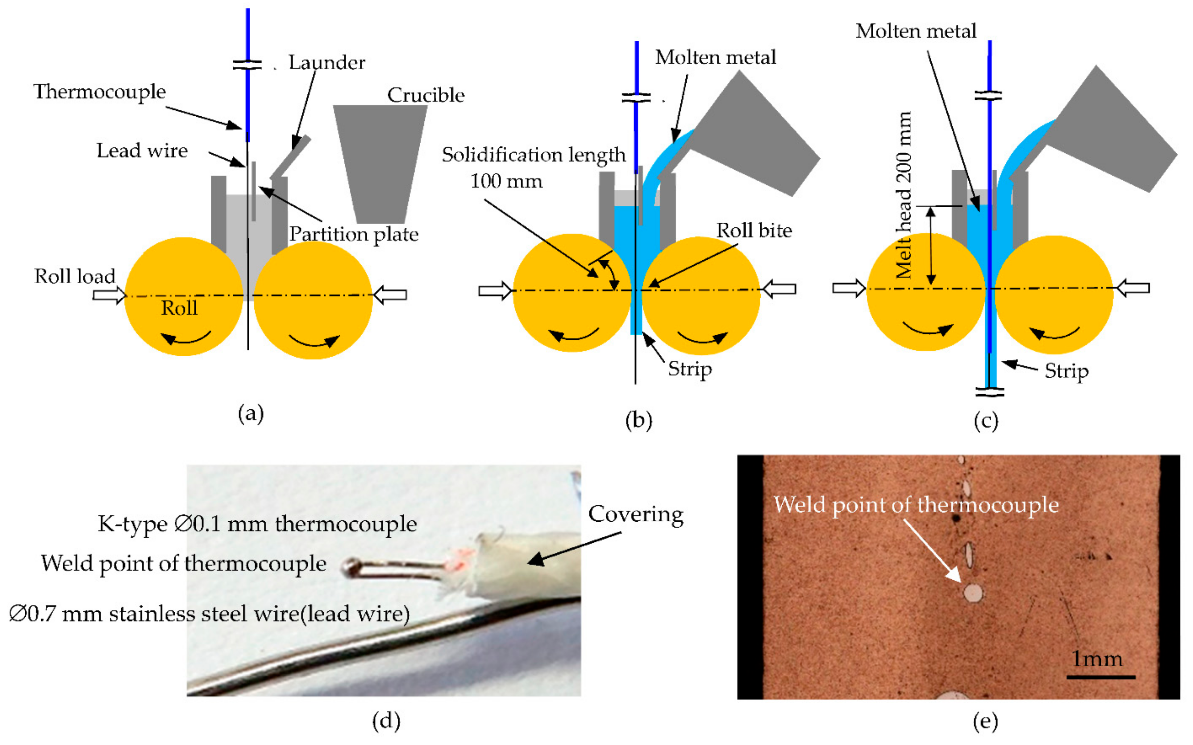
2. Experimental Procedure
3. Results
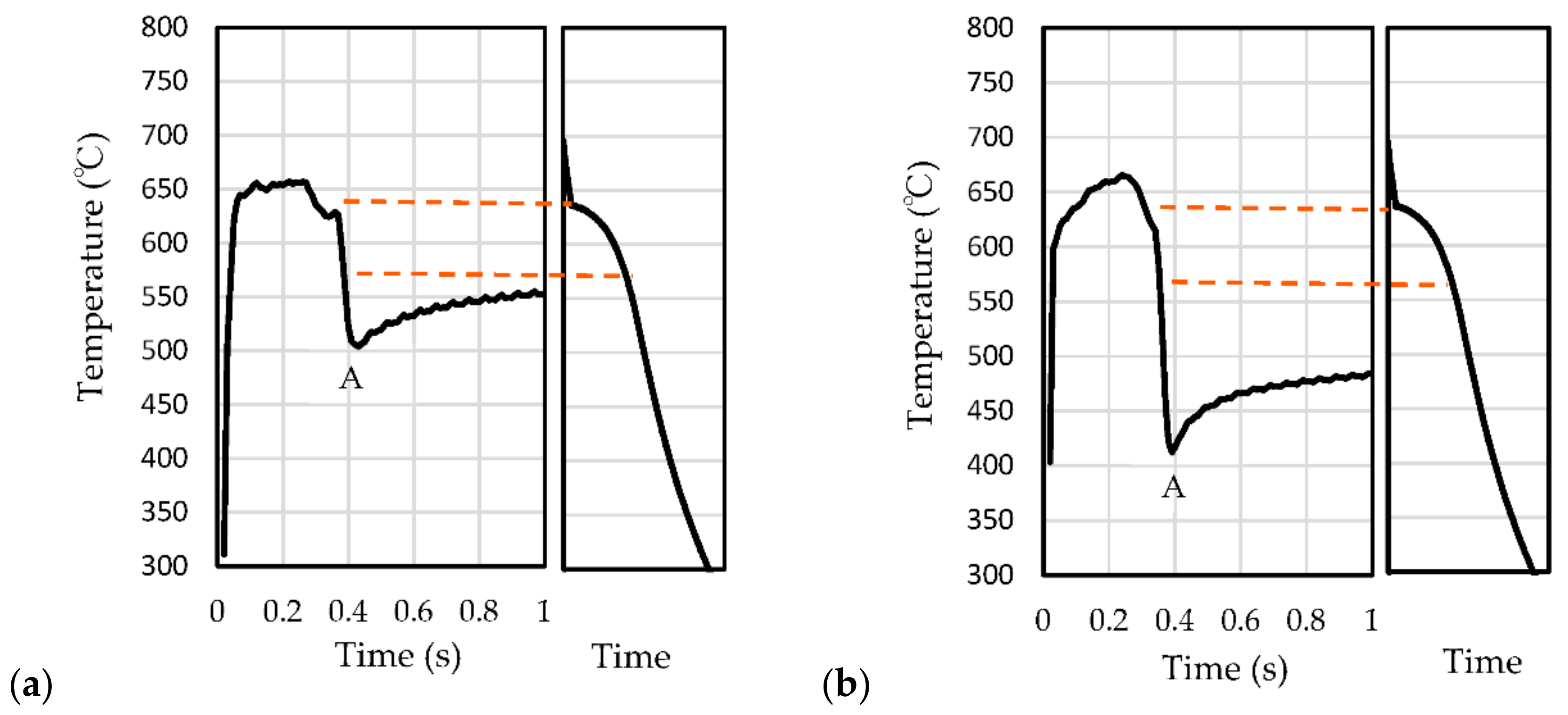
3.1. Cooling Curves
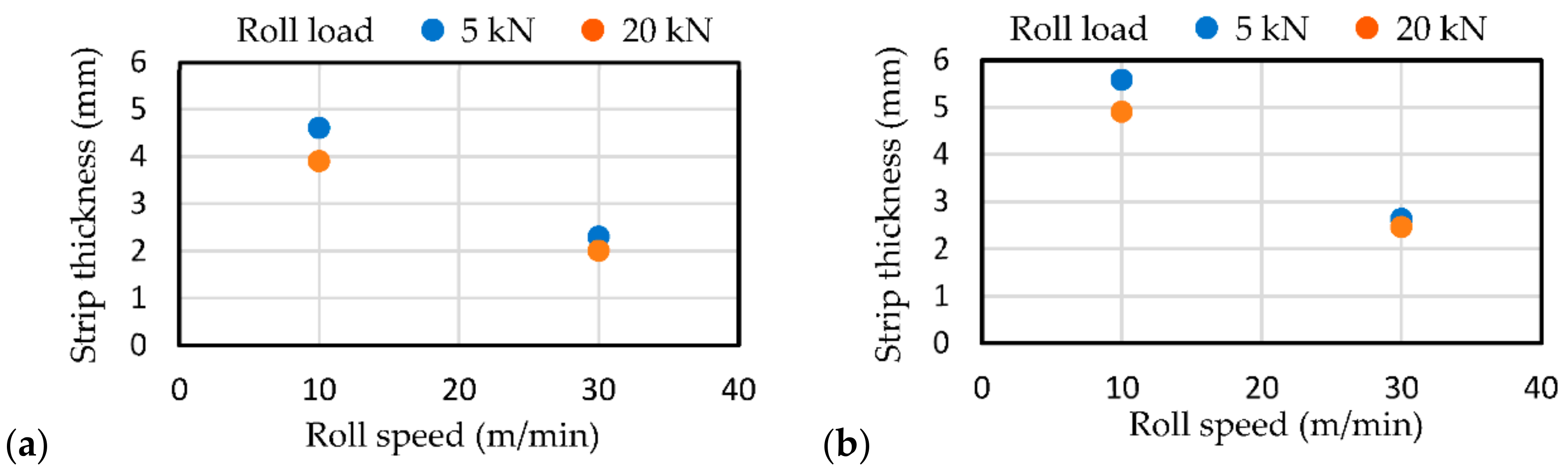
3.2. Strip Thickness
3.3. Strip Temperature at Roll Bite
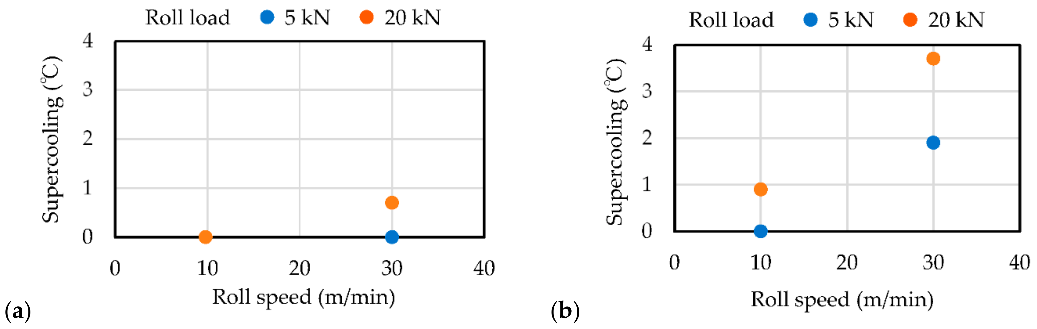
3.4. Supercooling
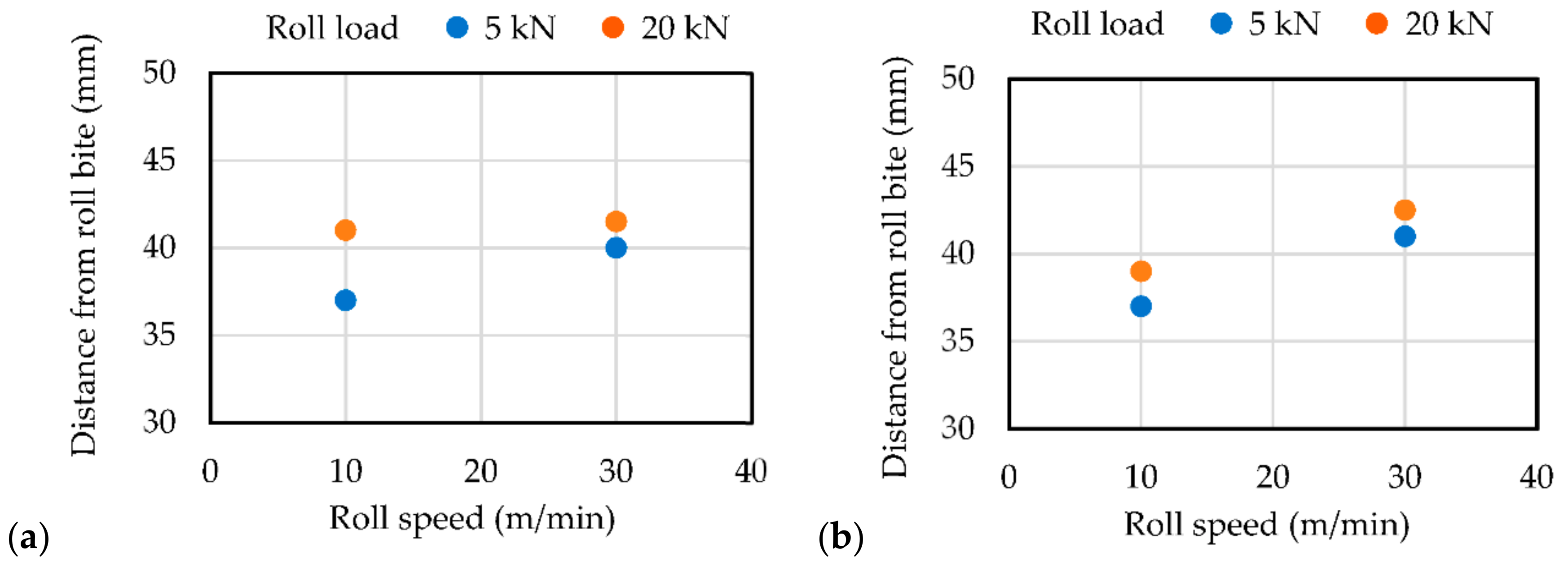
3.5. Solidification Starting Point
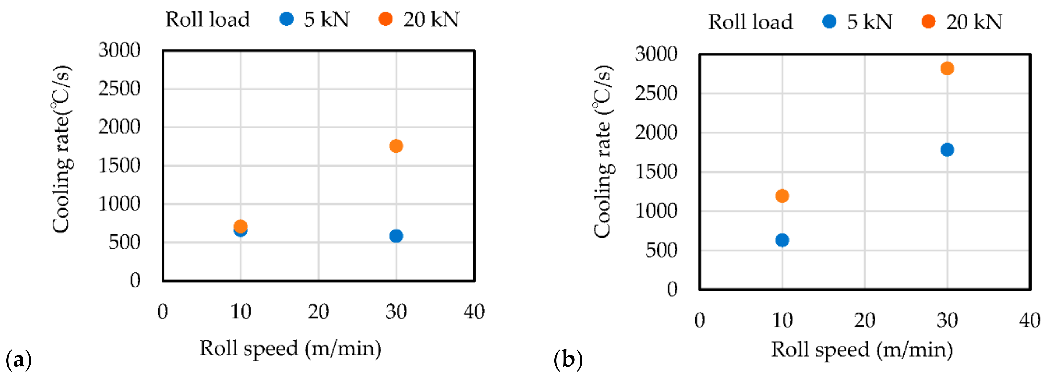
3.6. Cooling Rate
3.7. Strip Temperature after Exiting Roll Bite
4. Discussion
4.1. Cooling Curves
4.2. Strip Thickness
4.3. Strip Temperature at Roll Bite
4.4. Supercooling
4.5. Solidification Starting Point
4.6. Cooling Rate
4.7. Strip Temperature after Exiting Roll Bite
5. Conclusions
- (1)
- The strip thickness increased with the increase in the thermal conductivity of the roll and the decrease in rolling speed and roll load;
- (2)
- The distance from the roll bite to the solidification starting point ranged from 37 to 43 mm and increased with the decrease in strip thickness;
- (3)
- The liquidus temperature could be determined, but the solidus temperature could not be determined;
- (4)
- The degree of supercooling and the cooling rate increased with the increase in the thermal conductivity of the roll and the increase in rolling speed and roll load;
- (5)
- The strip temperature increased after leaving the roll, presumably because the strip interior was not solidified;
- (6)
- The strip temperature at the roll bite and after leaving the roll decreased with the increase in the thermal conductivity of the roll, rolling speed, and roll load.
Author Contributions
Funding
Institutional Review Board Statement
Informed Consent Statement
Conflicts of Interest
References
- Hamer, S.; Romanowski, C.; Taraglio, B. Continuous casting and rolling of aluminum: Analysis of capacities, Product ranges and technology. Light Met. Age 2002, 60, 6–17. [Google Scholar]
- Gras, C.; Meredith, N.; Hunt, J.D. Microdefects for mation during the roll casting of Al-Mg-Mn aluminum alloys. J. Mater. Process. Technol. 2005, 167, 62–72. [Google Scholar] [CrossRef]
- Daaland, O.; Espedal, A.B.; Nedreberg, M.L.; Alvestad, I. Thin gage twin-roll casting, process capabilities and product quality. Light Met. 2016, 3, 989–996. [Google Scholar] [CrossRef]
- Li, Y.; He, C.; Li, J.; Wang, Z.; Wu, D.; Xu, G. A novel approach to improve the microstructure and mechanical properties of Al-Mg-Si aluminum alloys during twin-roll casting. Metals 2020, 13, 1713. [Google Scholar] [CrossRef] [Green Version]
- Xu, Z.; Wang, S.; Wang, H.; Song, H.; Li, S.; Chen, X. Effect of cooling rate on Microstructure and properties of twin-roll casting 6061 aluminum alloy sheet. Metals 2020, 10, 1168. [Google Scholar] [CrossRef]
- Cook, R.; Cook, P.G.; Thomas, P.M.; Edmonds, D.V.; Hunt, J.D. Development of the twin-roll casting process. J. Mater. Process. Technol. 1995, 55, 76–84. [Google Scholar] [CrossRef]
- Taraglio, B.; Romanowski, C. Thin-gage/high-speed roll casting technology for foil production. Light Met. 1995, 1995, 1165–1182. [Google Scholar]
- Cortes, M. Pechiney-Jumbo 3 CM the new demands of thin strip casting. Light Met. 1995, 1995, 1161–1164. [Google Scholar]
- Nussbaum, A.I. Three-state-of-the-art Thin -gage high-speed roll caster for aluminum alloy sheet products. Light Met. Age 1996, 12, 8–19. [Google Scholar]
- Nussbaum, A.I. Three-state-of-the-art Thin-gage high-speed roll caster for aluminum alloy sheet products Part III. Light Met. Age 1997, 55, 34–39. [Google Scholar]
- Thomas, P.M.; Grocock, P.G.; Bouzendorffer, J.M. Dynamic strip caster- an update on the operation of the roll caster at Eurofoil. Melall. Plant Technol. Int. 1997, 20, 44–52. [Google Scholar]
- Haga, T.; Takahashi, K.; Ikawa, M.; Watari, H. A vertical type twin roll caster for aluminum alloy strip. J. Mater. Proc. Technol. 2003, 140, 610–615. [Google Scholar] [CrossRef]
- Haga, T.; Suzuki, S. Study on high-speed twin roll caster for aluminum alloys. J. Mater. Proc. Technol. 2003, 143–144, 895–900. [Google Scholar] [CrossRef]
- Haga, T.; Takahashi, K.; Ikawa, M.; Watari, H. Twin roll casting of aluminum alloy strips. J. Mater. Proc. Technol. 2004, 153, 42–47. [Google Scholar] [CrossRef]
- Haga, T. High Speed Roll Caster for Aluminum Alloy. Metals 2021, 11, 520. [Google Scholar] [CrossRef]
- Haga, T.; Inui, H.; Watari, H.; Kumai, S. Casting of aluminum alloy strip using an unequal diameter twin roll caster. Arch. Mater. Sci. Eng. 2008, 29, 113–116. [Google Scholar]
- Haga, T.; Nakamura, T.; Nakamura, R.; Harada, H.; Kumai, S.; Watari, H. Roll Casting of Al-SiCp Composite Strip. Adv. Mat. Res. 2010, 139–141, 481–484. [Google Scholar]
- Kim, M.S.; Kim, H.E.; Kim, S.H.; Kumai, S. Role of Roll Separating Force in High-Speed Twin-Roll Casting of Aluminum Alloys. Metals 2019, 9, 645. [Google Scholar] [CrossRef]
- Song, R.; Harada, Y.; Kumai, S. Influence of Cooling Rate on Primary Particle Solute Distribution in High-Speed Twin-Roll Cast Al-Mn Based Alloy Strip. Mater. Trans. 2018, 59, 110–116. [Google Scholar] [CrossRef] [Green Version]
- Haga, T.; Kurahashi, Y. Casting Process at Roll Bite in Strip Cast Using Vertical-Type High-Speed Twin-Roll Caster. Metals 2022, 12, 1169. [Google Scholar] [CrossRef]
- Ichikawa, R.; Ikeda, T.; Ohashi, T. Effects of Cooling Rate and Supercooling on the Solidified Structure of Various Aluminum alloys. J. JFS 1974, 46, 25–35. [Google Scholar] [CrossRef]


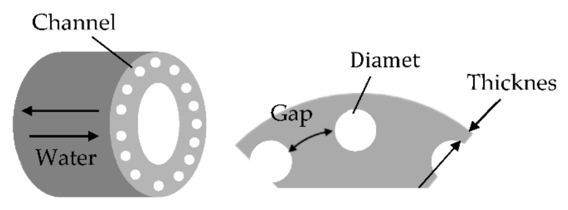
| Roll Type | Thickness (mm) | Gap (mm) | Diameter (mm) |
|---|---|---|---|
| Copper roll | 12 | 8 | 8 |
| Mild steel roll | 6 | 7 | 8 |
| Cu | Si | Mg | Fe | Zn | Mn | Ti | Pb | Sn | Cr | Al |
|---|---|---|---|---|---|---|---|---|---|---|
| 0.03 | 0.10 | 4.81 | 0.18 | 0.01 | 0.04 | 0.02 | <0.01 | <0.01 | 0.09 | Bal. |
Publisher’s Note: MDPI stays neutral with regard to jurisdictional claims in published maps and institutional affiliations. |
© 2022 by the authors. Licensee MDPI, Basel, Switzerland. This article is an open access article distributed under the terms and conditions of the Creative Commons Attribution (CC BY) license (https://creativecommons.org/licenses/by/4.0/).
Share and Cite
Haga, T.; Kurahashi, Y. Effect of Roll Material on Strip Solidification between the Rolls of a Vertical-Type High-Speed Twin-Roll Caster. Metals 2022, 12, 1699. https://doi.org/10.3390/met12101699
Haga T, Kurahashi Y. Effect of Roll Material on Strip Solidification between the Rolls of a Vertical-Type High-Speed Twin-Roll Caster. Metals. 2022; 12(10):1699. https://doi.org/10.3390/met12101699
Chicago/Turabian StyleHaga, Toshio, and Yukihiro Kurahashi. 2022. "Effect of Roll Material on Strip Solidification between the Rolls of a Vertical-Type High-Speed Twin-Roll Caster" Metals 12, no. 10: 1699. https://doi.org/10.3390/met12101699