Article

Influence of Pretreatment Strategy on the Crushing of Spent Lithium-Ion Batteries

by
Denis Manuel Werner
1,2,*,
Thomas Mütze
3 and
Urs Alexander Peuker
1
1
Institute of Mechanical Process Engineering and Mineral Processing, TU Bergakademie Freiberg, Agricolastraße 1, 09599 Freiberg, Germany
2
LIBREC AG, Fabrikstraße 4, 4562 Biberist, Switzerland
3
Processing Department, Helmholtz-Zentrum Dresden-Rossendorf (HZDR), Helmholtz Institute Freiberg for Resource Technology (HIF), Chemnitzer Str. 40, 09599 Freiberg, Germany
*
Author to whom correspondence should be addressed.
Metals 2022, 12(11), 1839; https://doi.org/10.3390/met12111839
Submission received: 2 September 2022 / Revised: 13 October 2022 / Accepted: 16 October 2022 / Published: 28 October 2022

Abstract

:
The rising production of lithium-ion batteries (LIBs) due to the introduction of electric mobility as well as stationary energy storage devices demands an efficient and sustainable waste management scheme for legislative, economic and ecologic reasons. One crucial part of the recycling of end-of-life (EOL) LIBs is mechanical processes, which generate material fractions for the production of new batteries or further metallurgical refining. In the context of safe and efficient processing of electric vehicles’ LIBs, crushing is usually applied as a first process step to open at least the battery cell and liberate the cell components. However, the cell opening method used requires a specific pretreatment to overcome the LIB’s hazard potentials. Therefore, the dependence on pretreatment and crushing is investigated in this contribution. For this, the specific energy input for liberation is determined and compared for different recycling strategies with respect to dismantling depth and depollution temperatures. Furthermore, the respective crushing product is analyzed regarding granulometric properties, material composition, and liberation and decoating behaviour depending on the pretreatment and grid size of the crushing equipment. As a result, finer particles and components are generated with dried cells. Pyrolysis of cells as well as high dismantling depths do not allow to draw exact conclusions and predictions. Consequently, trends for a successful separation strategy of the subsequent classifying and sorting processes are revealed, and recommendations for the liberation of LIBs are derived.

1. Introduction

Worldwide, battery development and production are of strategic importance in the context of the emission-free energy transition. A strong increase in electric mobility in several areas is expected to take place within the upcoming decade [1,2,3,4,5]. Simultaneous to LIB production, the development of highly resource-efficient processes for treating large LIBs after their EOL is important and necessary.
In general, LIBs cannot be incinerated or disposed into landfills due to safety and environmental issues [6,7]. Vehicle batteries, in particular, demand an adaption of the existing recycling processes due to their design, weight, sizes, high amount of valuable and critical materials, and stored amount of electrical energy [8]. On the European level, the upcoming battery regulation sets, besides the already existing mass-based recycling efficiency (RE) a material recovery rate (MRR) for contained key elements like lithium (Li), cobalt (Co), nickel (Ni) and copper (Cu) in two periods (2025 and 2030) [9]. On the one hand, the RE targets 65% in 2025 and 70% in 2030. On the other hand, the MRR of Li increases from 35% (2025) to 70% (2030), whereas Ni, Co and Cu increase from 90% (2025) to 95% (2030). Moreover, general recovery rates (RR) apply for waste electric and electronic equipment, waste (electrical) vehicles and other battery-containing equipment [10,11]. For example, waste electrical and electronic equipment (WEEE) falling within categories 5 and 6 (small information technology and telecommunication equipment) must be recovered by 75% and reused or recycled by 55%. End-of-life vehicles must fulfill a RR of 95% and RE of 85%.
Recycling of LIBs enhances resource and environmental protection and acts as a sustainable source of valuable materials such as Co, Ni, Cu, aluminum (Al), and Li for battery production, creating new occupations at the same time [4,12,13]. Moreover, battery costs and production emissions are reduced, and the application of electric mobility and stationary energy storage are promoted [14]. Ideally, the battery materials circulate in a closed loop within their lifecycle to aim for significant comprehensive benefits of the using LIBs regarding resources, the environment and the economy [5,8,15].
Although several LIB recycling processes are already commercialized [16], only a few can recover all of the above-mentioned materials. Addressing this, a general trend to open LIB cells by crushing requires a dedicated pretreatment strategy. The crushing step itself is crucial due to the release of the contained hazard potentials and materials. Crushing also forms the basis for an efficient subsequent mechanical and hydrometallurgical separation. However, transparent information and systematics for processing, including crushing and material separation, are rare, especially regarding the enrichment of the liberated materials by different separation methods into specific material fractions for further (metallurgical) refinement [17]. Therefore, systematic experiments were carried out to evaluate the influence of the pretreatment strategy on subsequent crushing.

2. Recycling of EOL LIBs

A structure of the applied processes for LIB recycling is given by Werner et al. [16]. Therein, the presented recycling chain with process steps and unit operations describes the three main process routes precisely. Moreover, a detailed review of the most used mechanical and physical processes can be found in Werner et al. [18]. Herein, the processes are clustered in process groups regarding the initial and potential material fractions. Furthermore, results from several combinations of pretreatment and processing steps, which includes manual dismantling, thermal pretreatment, crushing and thermal drying are shown in Werner et al. [19] and Werner et al. [20].

2.1. Design and Composition

The functional unit of LIBs is formed by a positive and a negative electrode as well as the separator and electrolyte. The negative electrode (anode) consists of a Cu foil as a current collector which is coated on both sides with graphite, binder and amorphous carbon compounds. The positive electrode (cathode) is based on an Al foil coated with layered transition metal oxides or phosphates. Moreover, carbon black and binders like polyvinylidene fluoride (PVdF) on the cathode side and carboxylmethyl cellulose (CMC) in combination with styrene-butadiene (SBR) on the anode side are added for conductivity and adhesion in the coatings, respectively [21,22,23,24,25]. With reference to the comprehensive review of Chen et al. [22], the binder must provide basically four functions: a dispersing agent and thickener (1), adhesion and cohesion (2), conductivity (3) as well as wettability (4). Adhesion and cohesion are facilitated via covalent, ionic, and/or metallic bonds. Consequently, the binder needs to be thermally stable up to 150 °C due to the requirements of the electrode fabrication process as well as the working temperature range (−20 to 55 °C). The separator prevents direct contact with the electrodes and consists of a porous plastic foil of a polyethylene (PE) core with polypropylene (PP) layers on both sides. The ion-conducting electrolyte is a mixture of different organic solvents, such as ethylene carbonate (EC), dimethyl carbonate (DMC), ethyl methyl carbonate (EMC) and diethyl carbonate (DEC), a conducting salt, predominately lithium hexafluorophosphate (LiPF6), and further additives. The electrolyte fills the pores of electrode coatings and separator foil.
The functional unit is produced as stacks, round or flat jelly rolls. This format defines the cylindrical and prismatic hard case cell types or the soft case pouch cell type, respectively [26,27]. The functional unit is in some cases enclosed by thin plastic foils and a hermetic housing forming a battery cell. The single cells are connected in series or parallel either to a single block or a module as a subunit of a larger battery system, respectively [16,28]. In battery systems, additional peripheral components are installed, such as the battery management system, cooling, packaging, and electronic and electric parts on the cell, module or system level. Altogether, LIBs show big differences in their material composition due to a variety of product generations, assembling techniques, cell types, number of battery cells, connections, as well as dimensions and masses [5,6,27,29,30,31,32,33,34,35].

2.2. Hazards and Waste Management

LIBs are considered as a hazardous waste due to their potential high voltage and state of charge, as well as their hazardous and reactive components [2,16,36,37]. Organic solvents can cause fire and explosion [38,39], and their hygroscopicity facilitates corrosion [29]. The chemical and thermal stability of the conducting salt is limited. Thus, the flammable and toxic gases can be generated as reaction or decomposition products during the battery lifetime, under abuse conditions or in worst-case scenarios [26,40]. Moreover, elements of the cathode’s coating material, such as Co and Ni, are considered noxious or even carcinogenic. Hence, LIB waste management requires high flexibility due to the great heterogeneity and complexity in the structure and composition of LIBs as well as their problematic ingredients [2,41,42].
The transformation from EOL LIBs to secondary raw materials is carried out by different strategies and methods, but follows, in principle, the recycling chain [16,43]. Interesting for the present article is the third process stage ‘processing’ using mechanical and physical methods [18]. Processing aims to break up the bonds between the individual components or even materials of the battery system, module or cell in order to separate them into defined concentrates, respectively [6,42]. Target materials by means of intrinsic material value and economic revenue are active materials (AMs) of the cathodes in particular [5,44]. However, also the other materials contribute to the RE and the overall economic efficiency.
The temperature, which is applied in thermal depollution, divides the industrial recycling technologies for EOL LIBs into three main processing routes (low, medium and high temperatures). Consequently, the effort for preparation, pretreatment and processing and thus the technical recyclability varies for each route [16]. The low-temperature route enables the recovery of organics, plastics and graphite and consequently achieves the highest technical RE. However, this route must focus especially on measures for safe material processing, including procedures for handling, dismantling and electrical depollution of the LIB systems, modules or cells, as well as the process medium for liberation [19,20]. In contrast, the medium-temperature route applies thermal depollution in terms of pyrolysis or thermolysis. Thermal depollution uses the thermal decomposition (pyrolysis) or chemical reaction (thermolysis) of organic materials through the application of elevated temperatures (>500 °C), mostly in the absence of oxygen, into defined products [6,35,42,44,45,46,47]. The medium-temperature route enables the replacement of the elaborate discharging step in terms of time and space as well as work safety, especially for small consumer batteries and crushing under normal dedusting equipment [20]. However, high-energy consumption for thermal depollution, elaborate off-gas treatment and a reduced RE are the throwbacks of the medium-temperature route.

2.3. Thermal Treatment of LIB Components

The influence of temperature and its complex interactions on the materials of the functional unit are theoretically discussed in detail in the following section. Furthermore, the principles of crushing metals and scraps and their consequences on LIB materials are summarized and connected to the influence of the thermal treatment.

2.3.1. Material Behavior

High temperatures change the functionality of the cells’ material and can cause thermal runaway, particularly in charged cells [48]. Table 1 shows material-specific temperatures for the thermal stability of the respective binder, the beginning of decomposition for pristine and used materials and their maximum adhesive strength. Furthermore, the degradation and shrinkage temperatures are added as well as the melting point of the separator, the thermal stability and degradation limits of the conducting salt LiPF6.
The thermal properties of the binders play a crucial role in mechanical processing, as they are responsible for the adhesion of the coatings. The repeal of their adhesion is decisive for material separation and overall economic efficiency. Furthermore, the binders protect the active and conductive materials as well as metallic current collectors from corrosion and the electrolyte from depletion [25]. Hanisch et al. [50] studied the adhesion between electrode coatings and the respective current collector foil with the Haselrieder–Westphal–Bockholt method [60] within 100 and 500 °C. They found a maximum adhesive strength at 300 °C for cycled anode coatings and at 400 °C for cycled cathode coatings. This increase is caused by structural changes and rearrangement of the binder after melting as well as an increased binder crystallinity. The latter leads to a more brittle breakage behaviour of the electrode coatings, resulting in flake-like particles instead of compact spheres. Consequently, decoating of the electrodes becomes more difficult, occurring only at the edges of the flaky pieces.
Above 300 °C for anodes (400 °C for cathodes), the adhesive strength is significantly decreased due to the decomposition of the binder during pyrolysis (cf. Table 1) [50]. The SBR and CMC binder of the anode decompose at around 240 °C and 400 °C in cycled anodes, whereas PVdF decomposes at 450 °C in cycled cathodes. Compared to virgin electrodes, the decomposition temperatures are lower due to structural breathing while charging and discharging the batteries [21].
The separator materials PE and PP melt at 135/165 °C and start to decompose at around 165 °C due to thermooxidative degradation of the polymer chains. This degradation significantly enhances brittleness and results in yellowing [61]. The conducting salt LiPF6 decomposes at temperatures above 70 °C, generating lithium fluoride (LiF) and phosphorus pentafluoride (PF5) [59]. The melting points of the current collectors’ metals are higher than the temperatures of thermal depollution and pyrolysis. However, corrosion can occur due to the reaction with halogenated hydrocarbons generated by the degradation of the conducting salt and binder [62,63,64]. The AMs of the cathode and anode (LCO and NMC, LFP, NCA, and graphite) remain stable up to 250 °C, 600 °C, 580 °C and 600 °C, respectively [21,50].

2.3.2. Crushing of LIB Compounds

The crushing principles of scrap and metal compounds were investigated thoroughly under ambient conditions at different stress modes [65,66,67,68]. With reference to these works, Wuschke [39] found that especially bending of the electrodes causes cracks in the coating layers as well as between the coating and the current collector foils. Besides decoating, bending deforms the metallic foils towards spherical particles.
In general, adhesion failure between coating and collector foil can be distinguished from cohesion failure (rupture within the coating layers) [69]. The cohesive strength between the Cu foil and its anode coating is usually weaker [14] than the cathodes’ coating on the Al foil [23,69,70]. However, after thermal treatment above 55–60 °C, representing the upper working range of LIBs, the material properties change, which influences the breaking behavior as well as the recovery in the respective particle size class. The coating materials are better liberated, and the separator and Al foil become more brittle. Both effects lead to a higher amount of fines after mechanical stressing.

2.4. Aim of This Contribution

In particular, the hydrometallurgical refinement of cathode AMs is intensively analysed [33,44,70]. Within this, mechanical processing, in particular crushing and sieving, is often used only for conditioning and preparation purposes. Nevertheless, most often, knowledge is missing regarding the particle properties and processing behavior of the output materials from pretreated and crushed batteries. Thus, the scale-up of these mechanical processes for commercialization remains difficult to facilitate and needs further studies like the present one [71].
Additionally, studies have been carried out on cell crushing with the main focus on the energy input for crushing different battery types [72], the degree of liberation and the emissions produced during or after crushing [29]. However, battery types and geometries, depollution strategies and dismantling depths as well as crushing machines differ within the studies, hindering the comparability of the results [42]. Moreover, a detailed analysis of the material composition is rarely found [33,42,73]. We attempt to overcome this inconsistency in the present contribution by the selecting of a very defined experimental setup.
To conclude, the influence of varying dismantling depths and depollution temperatures within pretreatment on the mechanical liberation of the respective input material had to be investigated by systematic experiments to quantify and evaluate different processing strategies [19,20]. Each crushing product was thermally dried and subsequently analysed in terms of granulometric properties and material composition. This enables us to derive the degree of liberation (decoating) and to suggest adequate separation methods and an overall processing strategy.

3. Materials and Methods

In this contribution, one defined LIB cell is systematically investigated regarding liberation and size reduction. All crushing products are classified in terms of analytical sieving, and the material composition of the generated particle size fractions is determined. In addition, the degree of liberation of all components as well as the degree of decoating of the individual electrodes is calculated.

3.1. Materials

A prismatic cell from an electric vehicle (Samsung SDI, Yongin-si, South Korea; capacity: 94 Ah; charging voltage: 3.68 V; cell mass: 2038.4 g; 172 mm × 125 mm × 45 mm) was used as test material. The initial battery system consisted of eight modules and twelve prismatic cells and was dismantled manually to the cell level (cf. Figure 1a) [19,74]. The cells contained a rectangular bursting membrane between the outer electric contacts of 36 mm × 12 mm (cf. Figure 1b). Electrical discharging was carried out on the module level. The battery system was not used in an electric vehicle but was subjected to charge and discharge cycles. Therefore, it is assumed that all cells were exposed to the same working conditions and therefore had a similar state of health.
Table 2 shows the material composition of the battery cell. The amounts of the solid components, including the cathode, anode, separator and housing, were determined by reverse engineering by manual cell opening, material separation and weighing. The amount and detailed composition of the organic solvents, conductive salt and additives were estimated qualitatively.

3.2. Equipmental Setup

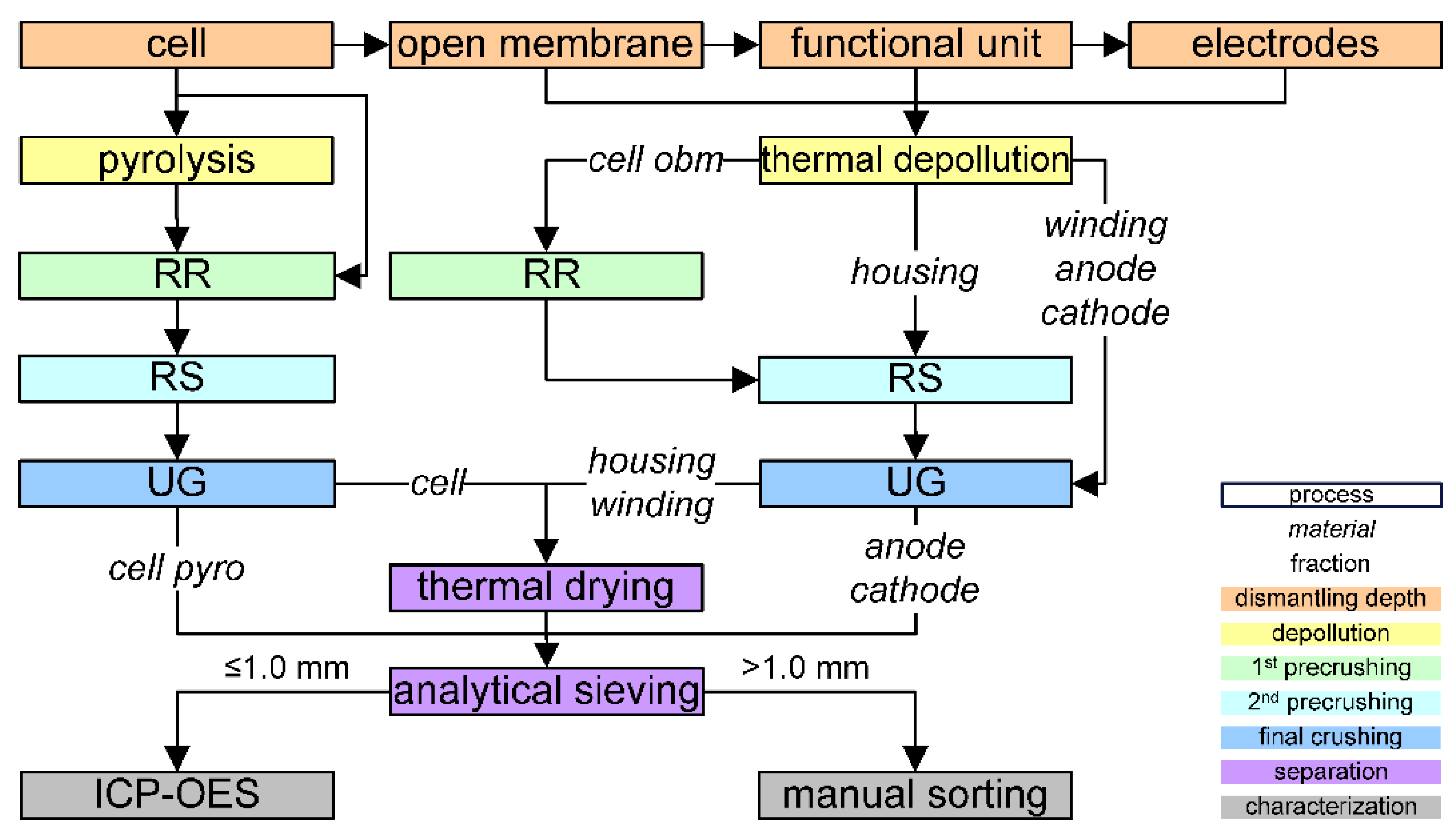
Several multistep crushing experiments were performed on a semi-industrial scale. On the one hand, the cells were either directly fed to crushing and thermally dried afterwards or pyrolyzed beforehand (cf. Figure 2). Pyrolysis was conducted at 575 °C for 1 h under a nitrogen atmosphere and atmospheric pressure without thermal drying after crushing. On the other hand, the bursting membrane was opened or the cells were manually dismantled before thermal depollution at different temperatures. The procedures for dismantling and depollution were described by Werner et al. [19], whereas thermal drying after crushing was described by Werner et al. [20]. For monitoring the thermal depollution and drying process, the temperatures (80 °C and 120 °C) were set with the control cabinet of the used oven. Cell dismantling reached from the separation of the housing and four windings down to the separation of the anode, cathode and separator foil.
For each setup, three cells were used independently. Thus, in total, 63 cells were prepared for the experiments to evaluate the crushing behavior, specific mechanical energy input and particle size distribution.
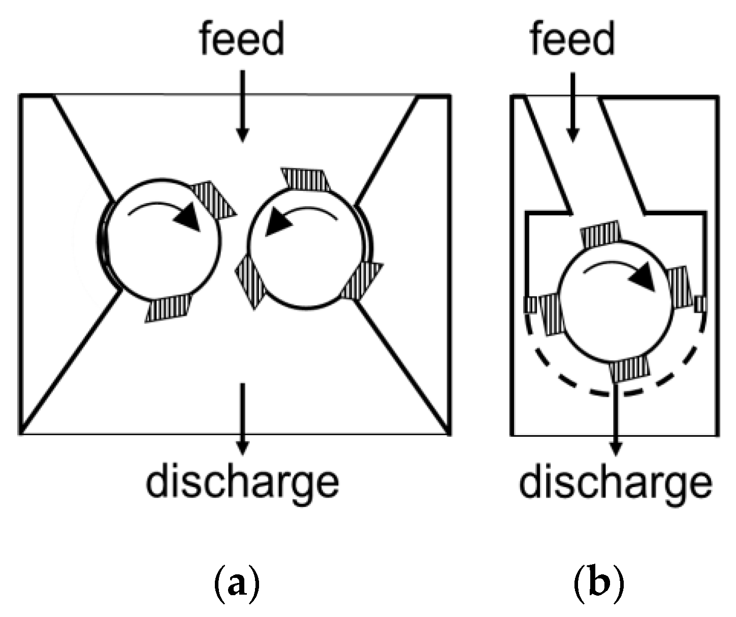
Independent of the pretreatment and depollution strategy, two different semi-industrial machines were employed for crushing [39,72,75]. Precrushing was performed by a slowly rotating, two-shaft rotary shear at a circumferential speed of 0.3 m/s [76] (cf. Figure 3a). This machine is self-built by the Institute for Mechanical Process Engineering and Mineral Processing (Freiberg, Germany). The 40 mm crushing tools of the rotary shear are shaped to be punctiform with a 20 mm axial gap between the tools (RR mode, primary crushing) or linear when operated without a gap (RS mode, secondary crushing) [66]. Consequently, the stress modes in precrushing are combined shear and tear stress, and in final crushing, they are mere shear stress.
Final crushing was carried out by a fast-rotating, one-shaft rotary shear (UG, MeWa Andritz Universal Granulator UG 300, Hechingen, Germany) at a circumferential speed of 6.4 m/s. This machine is also known as a cutting mill and utilizes an exchangeable outlet grid (round opening sizes: 10, 20, 30, 40 mm; Figure 3b). The design of all crushing steps has been linked to the particular feed material (cf. Figure 1) since, e.g., windings, anode, cathode and separator foils have been too thin for reasonable precrushing. The respective input material (cell, cell fragments, or cell components) was crushed individually with simultaneous dedusting by a mobile system (RUWAG DS2, Melle, Germany). The dedusting system included an activated carbon filter to reduce the impact of the gases released during mechanical cell opening.
After crushing, some of the materials were dried for 120 h at room temperature or at 80 °C in an oven (HERAEUS t 6420, Hanau, Germany) to remove the remaining volatile electrolyte components [19,20]. After this preparative drying, sieving analysis was performed in a Haver EML 450 digital plus (Haver & Boecker, Oelde, Germany) for 10 min each. The material was classified into 13 size fractions at 0.5/1.0/2.0/3.15/5.0/8.0/10.0/10.0–12.5 mm, 12.5–16.0 mm, 16.0–20.0 mm, 20.0–25.0 mm, 25.0–31.5 mm and >31.5 mm.
In addition, one cell was investigated regarding the material composition of the experimental process route. On the one hand, two fractions below 1 mm were analyzed by inductively coupled plasma optical emission spectrometry (ICP-OES) CETAC ASX-260 (Thermo Fischer Scientific, Waltham, United States of America). Therefore, the fractions were milled in a vibratory mill Pulverisette 6 (Fritsch, Kitzingen, Germany) for 5 min and dissolved in aqua regia. On the other hand, the fractions above 1 mm were manually sorted into fragments of the individual LIB components (anode, cathode, thick Al, thick Cu, thick plastics, thin plastics, separator, (liberated) coating and compounds). Therein, compounds are understood as particles consisting of different battery components. Anodes and cathodes cluster the Cu and Al foils containing the respective active materials. The size classes were split in riffle splitters down to at least 1000 particles each to keep the time for manual sorting within reasonable limits. However, the coarse size classes often consisted of significantly fewer particles.
The anode and cathode fragments differed in the degree of delamination (see Section 3.3). The thick metals (Al, Cu), as well as the thick and thin plastics, form the housing. The coating fraction covered the decoated material from the metallic current collector foils, being a mixture of active material and/or graphite as well as remaining binder, additives and electrolyte components, depending on the depollution strategy.

3.3. Methods

For each crushing step, the mass-specific mechanical energy input wm was calculated for all materials. In Equation (1), t0 and t1 mark the start and end of crushing, P(t) represents the power draw during crushing. PL indicates the idle drive power, and mF is the feed mass for the respective crushing step.
w m = w m F = t 0 t 1 P t d t P L m F
Above 1 mm, the mass m of manually sorted components j within in the respective particle size fractions k was weighed in order to determine their relative mass wj,k (Equation (2)) and the overall material composition. Below 1 mm, the relative mass of Al and Cu obtained by ICP-OES was related to the cathode and anode components, respectively.
wj,k = mj,k/mk
Consequently, the material recovery Rc,j of one component is determined as the product of mass recovery in the respective size class Rm,k and its relative mass wj,k related to its relative mass in the feed wF,j. In the present contribution, the material recovery Rc,j of one component will always be drawn as cumulative recovery for the particle size fractions.
R c , j = R m , k w j , k w F , j
According to Schubert [77], the degree of liberation A is calculated as the mass ratio of totally liberated particles mlib,j of component j compared to the total amount of the compound in the sample mtot,j [75].
Aj = mlib,j/mtot,j
This also fits the calculation of the degree of decoating AD of the electrodes (cathode AD,c, anode AD,a). Here, the mass of liberated coating material is related to the electrode coating in the feed (cf. Table 2).
AD,j = mliberated coating,j/mtotal coating,j
In the literature, similar measures, such as second degree of liberation [75], compound separation efficiency for the coating (CSEcoating) [50,78] or peel-off efficiency [70], can be found for this.

4. Results and Discussion

At first, the mass-specific energy input for crushing is shown for (non) pretreated cells, compounds, components and materials. Hence, the operational efforts can be derived for better production and financial planning as well as the use of adequate crushing equipment.
After that, the fragment size distribution gives the first hint towards different pretreatment strategies and their general influence on the crushing and liberation behavior with respect to shifts toward finer or coarser fragment and particle sizes.
As a result, the degree of liberation and degree of decoating will be calculated in order to explain the breakage behavior between the main components, the AMs and metal electrode foils and the shifts in the fragment size distributions.
Finally, the selective breakage behavior of the different components and materials will be exploited, enabling a more detailed understanding of the operations during the crushing process as well as the choice of the subsequent mechanical separation methods and technologies.

4.1. Energy Input for Crushing EOL LIBs

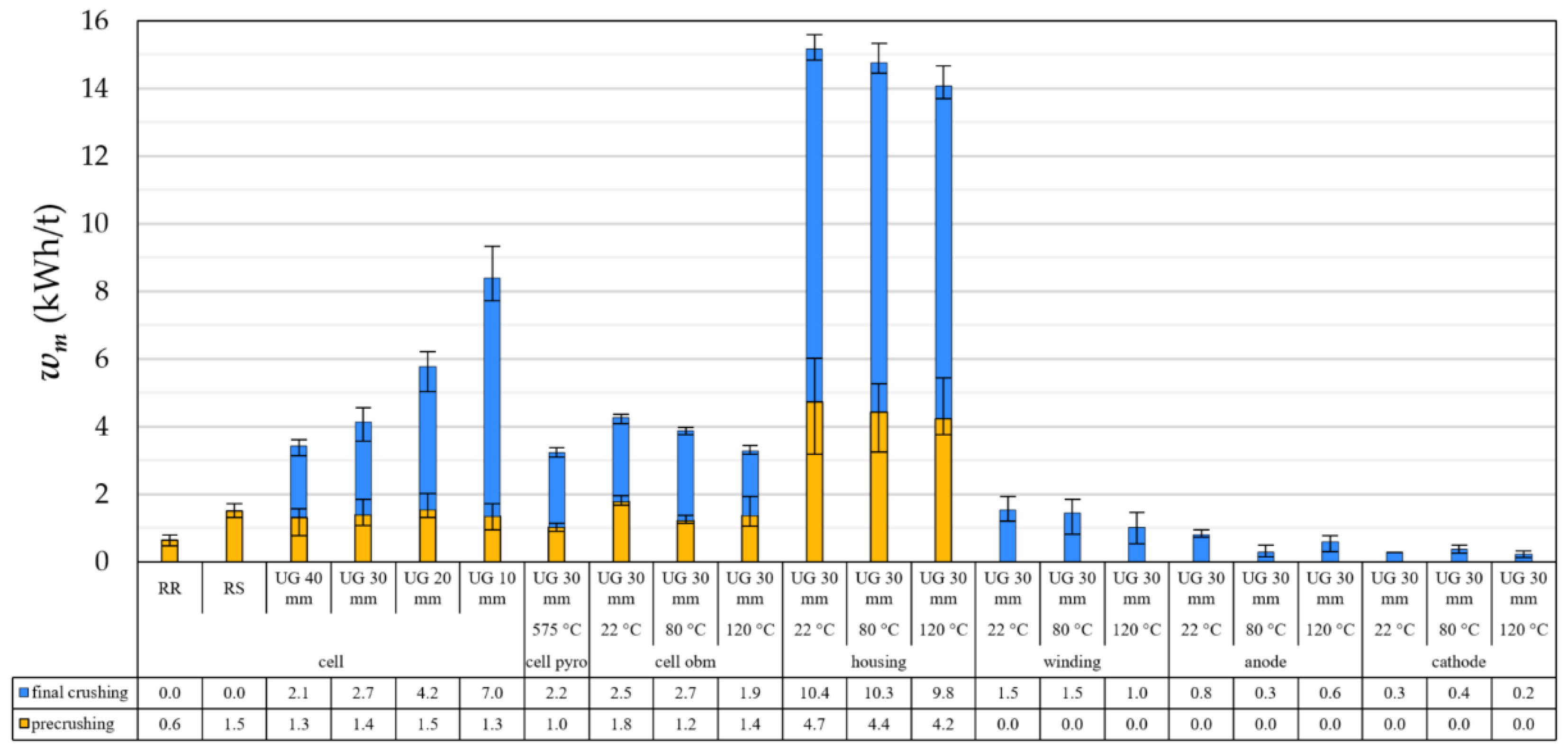
Figure 4 compares the specific energy input of different feed materials and combinations of crushing steps without previous thermal depollution. As explained in Section 3.1, whole cells can be compared to cells with open bursting membrane as well as to individual parts of the battery cell. The error bars represent the minimum and maximum value of the experimental results based on three separate cells used for every single setup (cf. Section 3.2). As expected, the mass-specific mechanical energy input of whole cells increases significantly with each crushing step and decreasing opening size of the cutting mill UG grid due to higher residence time and more stressing events. The results fit values from the literature for similar cells [39,72].
The thermal depollution of cells with an opened bursting membrane at 22 °C, 80 °C to 120 °C results in a slight decrease in the specific energy input. One reason is the lower tensile strength of the separator as a consequence of the thermal treatment. Nevertheless, the cells with thermal depollution at 22 °C show comparable results to the cells without thermal depollution crushed with the same grid size. Additionally, the cells with thermal depollution at 120 °C behave similarly to the pyrolyzed cells.
Crushing assemblies or single components of the battery cells leads to strongly differing results. In particular, the housing requires a significantly higher specific energy input during precrushing as well as final crushing. Against expectations, thermal depollution shows a slight influence on the crushing of housing. This effect can be explained by the degradation of the plastic components in the housing due to the thermal treatment. Overall, the specific energy input of housing is compared to the whole battery cells due to the relatively low amount of thick aluminum case in the battery cells (see Table 2).
Compared to all these cases, the specific energy input for crushing windings or single electrodes is significantly smaller due to their low material thickness. Usual current collector foils have a thickness of app. 15 µm with an app. 150 µm coating layer [26]. The separator foils are porous and have a typical thickness of 25 µm [26]. The depollution temperature has a negligible influence on depolluted cells with open bursting membrane.
For crushing the electrodes alone, no clear trend regarding the influence of the depollution temperature is recognizable, especially since the specific energy input is very low and in the range of measurement accuracy.
Wuschke [72] offered an estimation of the specific energy input for cells as the weighted sum of the specific energy input of the single components (Equation (6)).
w m ( T d ) = i = 1 n w m , j ( T d ) × w j   ( T d )
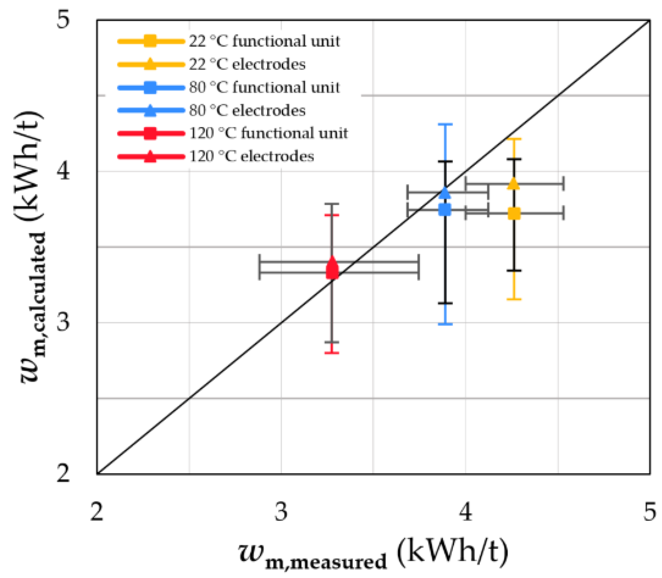
He proposed the individual relative mass wj of each component as a weighting factor. That assumption is visualized in Figure 5, comparing the measured specific energy input of cells with open bursting membrane with the calculated one for different depollution temperatures Td and dismantling depths. The dismantling depths have been distinguished into functional units (housing and windings) as well as electrodes (housing, individual electrodes, separator). The error bars represent the minimum and maximum value of the experimental results based on three separate cells used for every single setup (cf. Section 3.2). In an ideal case, the values are close to the line of equality.
The comparison of calculation and measurement shows the good accuracy of the model, especially for depollution temperatures above 80 °C. In the calculation, the data for the separator is missing because this material cannot be crushed in the specified equipment. Therefore, this specific energy input was calculated as the difference between the data of the windings and the data of the electrodes (cf. Table 3).

4.2. Fragment Size Distribution

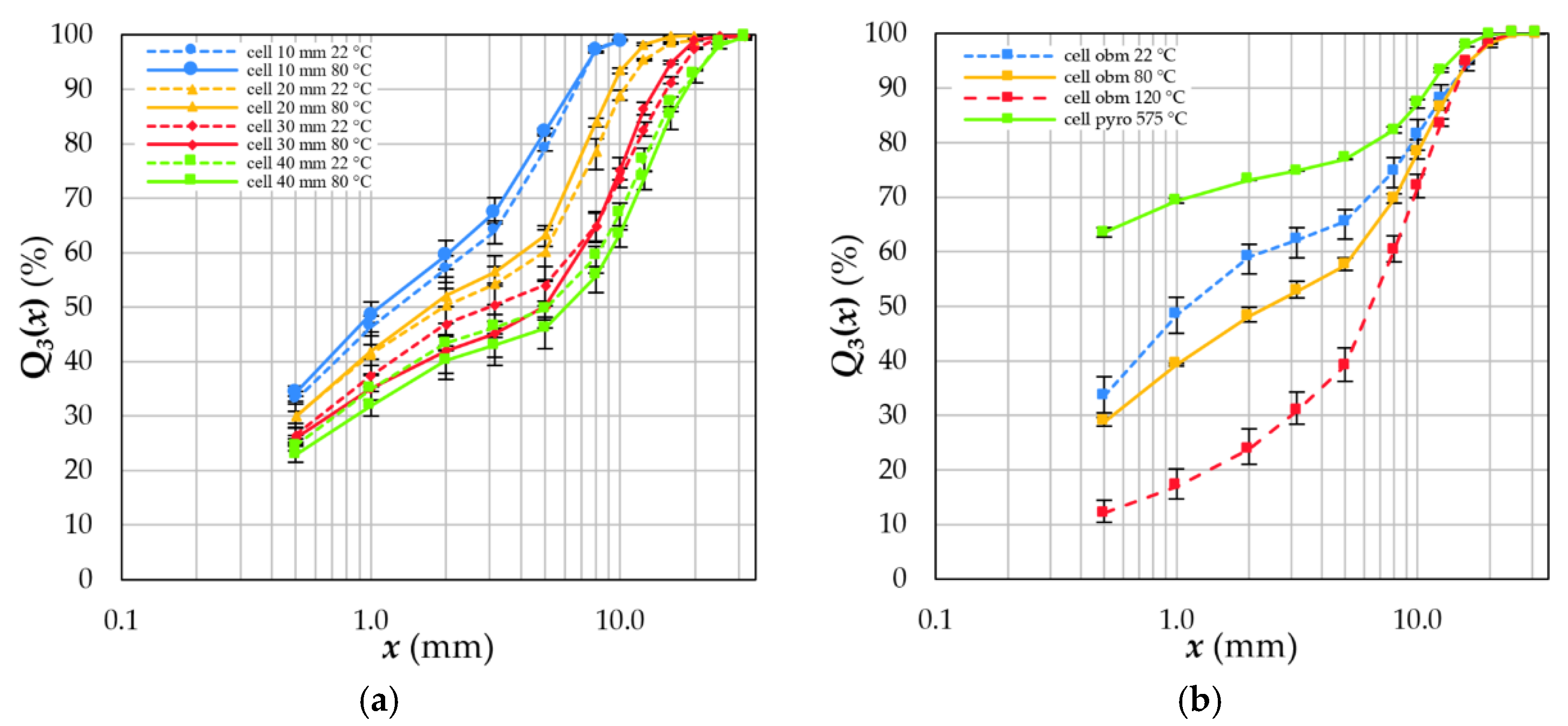
As expected, a general trend of finer fragments with decreasing grid size of the cutting mill is recognizable (cf. Figure 6a) independent of the depollution temperature. Therein, a relatively small difference in the fraction smaller than 0.5 mm occurs due to the similar breakage behaviour of the electrode foils and, likewise, delamination. The drying temperature has no influence.
In contrast, the influence of the thermal treatment on the fragment size distributions is clearly visible (cf. Figure 6b). Increasing temperatures during thermal depollution affect the adhesion strength of the electrodes’ coatings as well as the tensile strength of the separator. Below 120 °C, the distributions shift with increasing depollution temperatures towards coarser fragment sizes following the decreasing specific energy input (see Section 4.1 and Figure 4). Above 120 °C, the pyrolyzed cells show a much higher amount of fines at a comparable specific energy input caused by the decomposition of binders and separators.
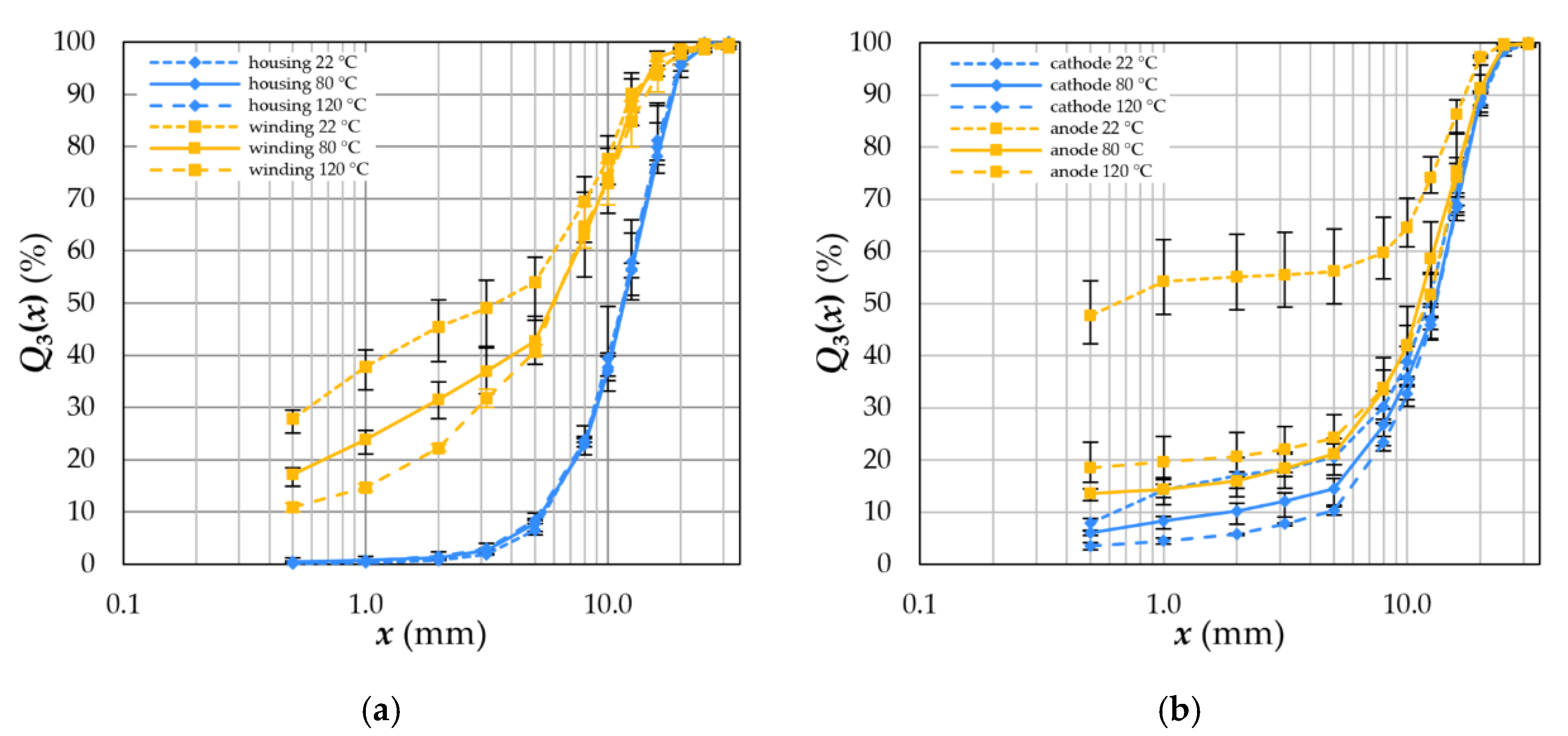
The housing also shows no influence of the depollution temperatures on the product sizes (cf. Figure 7a), and only a few particles are generated below 3.15 mm. The housing consists of a robust prismatic shell (alloyed Al), electrical contacts (Al and Cu) and small amounts of compact plastics. Their crushing behavior is not changed since the applied temperatures have no impact on their material properties. This also confirms the assumption that the specific energy input must remain constant (cf. 4.1). Temperature has a similar effect on the fragment size distributions of windings (cf. Figure 7a) and electrodes (cf. Figure 7b), as has been shown for cells with open bursting membrane (cf. Figure 6b).

4.3. Degree of Liberation and Degree of Decoating

The crushing products generated from different pretreatment and cell opening methods were dried at 22 °C or 80 °C for at least one hour up to 120 h. The results are shown in Figure 8 regarding the dismantling depth, depollution temperature and the equipment of the last crushing step. Since crushing aims not only at size reduction in recycling applications, the degree of liberation as well as decoating of the electrodes were also investigated. For whole cells, the degree of liberation of the individual components is nearly independent of the grid size in final crushing (cf. Figure 8a).
In contrast, the degree of decoating of the electrodes increases with decreasing grid size following the increasing energy input described in Section 4.1. As known from the literature [39], the anodes show a higher degree of decoating than the cathodes due to the differing binder properties.
Compared to this, the cells with open burst membrane and pyrolyzed membranes show a slightly smaller degree of liberation, around 90%, for the investigated temperatures (cf. Figure 8b). For the electrodes, the degree of decoating is also around 90% and, therefore, much higher than untreated cells if thermal depollution at 22–80 °C or pyrolysis is used. Pyrolysis especially increases the decoating of the cathode. The anodes show no enhanced decoating, although their binder should be completely decomposed at 575 °C (cf. Table 1). However, both the degree of liberation and the degree of decoating do not correlate with the specific energy input during crushing (see Section 4.1 and Figure 4).
At higher dismantling levels down to windings, the trends look similar to the mechanically opened cells (cf. Figure 9a). For dismantling down to the electrodes, only the degree of decoating was calculated since the electrodes are already fully liberated due to the dismantling (Figure 9b). Similar to cells with open burst membrane, the degrees of decoating drop with higher depollution temperatures, showing the lowest results of all investigated materials. Pyrolysis of the electrodes was not available. Since the specific energy input remains constant (see Section 4.1 and Figure 4), decoating is mainly influenced by the depollution temperature.

4.4. Exploitation of the Selective Breakage Behaviour

As shown in Section 4.2, the individual components of LIBs break selectively, which means an enrichment in individual size classes. This effect can be exploited by separation via sieving and can be described by the cumulative recovery defined in Section 3.2. The interdependencies between crushing behavior, dismantling depth, and thermal depollution on enrichment are presented in the following for the individual battery components.

4.4.1. Separator Foil and Housing

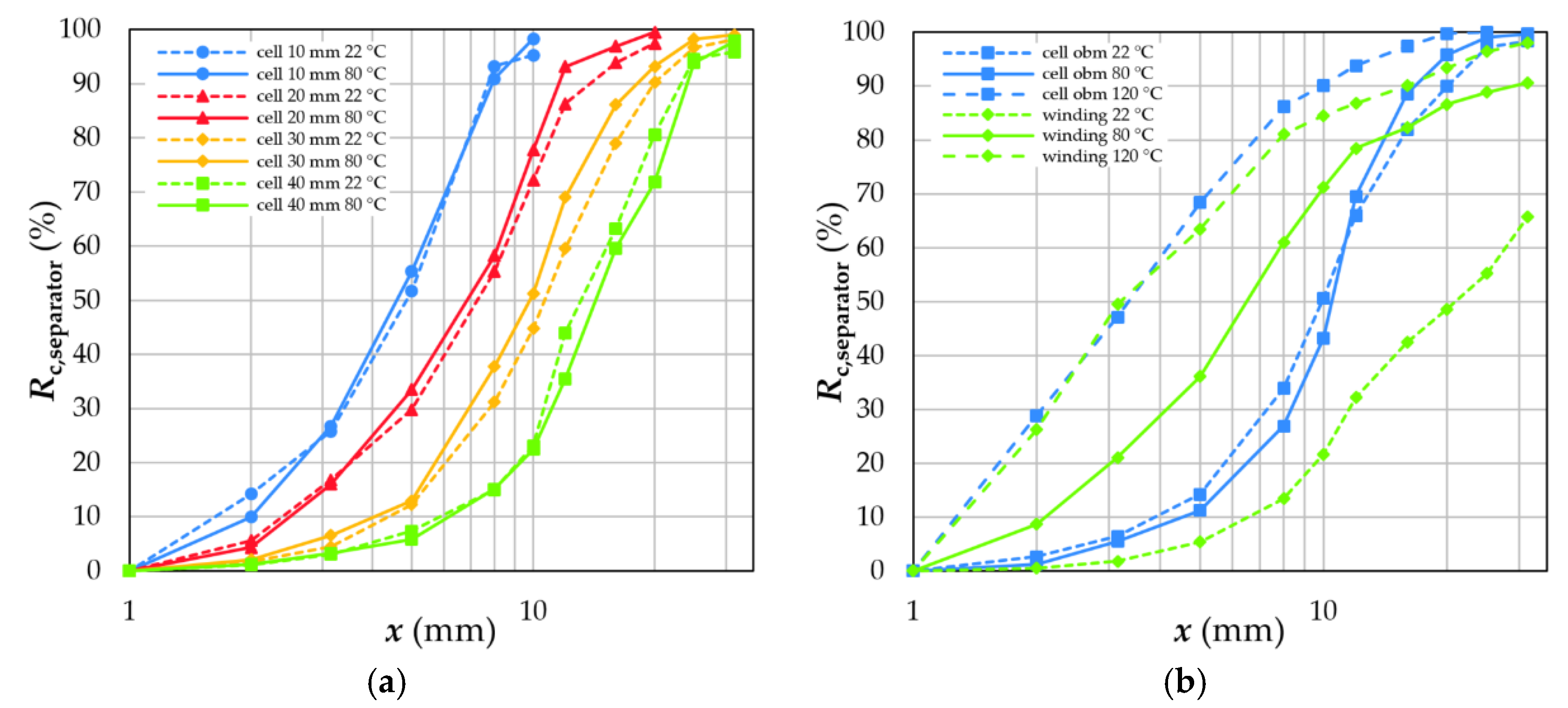
The separator foil makes up about 1.9% of a LIB cell (cf. Table 2). Independent of the preparative drying temperature (see Section 3.2), fragments of the separator foil show basically all sizes above 1°mm (cf. Figure 10a). The distributions become narrower with decreasing grid size since the upper fragment size decreases due to the smaller grid openings and a concurrent fixed lower fragment size due to the stability of the foil. After an initial thermal depollution, separator fragments of cells with open burst membrane or of windings are finer due to a more brittle breakage behavior as a consequence of their thermal treatment (cf. Figure 10b).
Thereby, the tensile strength of PP and PE decreases, resulting in finer particles during mechanical stressing. The amount of separator fragments below 1 mm is very small and cannot be analysed via ICP-OES due to its working principle. It can be estimated to app. <1%. No separator fragments can be found in the recycling products of pyrolized cells since plastics are fully decomposed during pyrolysis.
The housing makes up about 15.7% of a LIB cell, of which the robust aluminum casing contributes the most, with 75.2% (cf. Table 2). This is also the main reason why the housing materials are recovered in the size fractions above 2 mm being not influenced by any thermal treatment (cf. Figure 11b and Section 2.3.1). As with the separator, the width of the fragment size distribution is influenced by the grid size (cf. Figure 11a).

4.4.2. Electrodes

Fragments of both electrodes (cf. Figure 12) are mostly recovered in size fractions above 1 mm. Again, the size distributions shift with decreasing grid size towards finer size classes. The drying temperature has no significant effect on the recovery. However, particle shape and the degree of decoating differ in the investigated particle size classes (see Section 4.3). In the coarse fractions, the particle shape is more of the original foil with low decoating. In contrast, crushing leads to the deformation of the foils towards more compact and cubic particles with higher decoating.
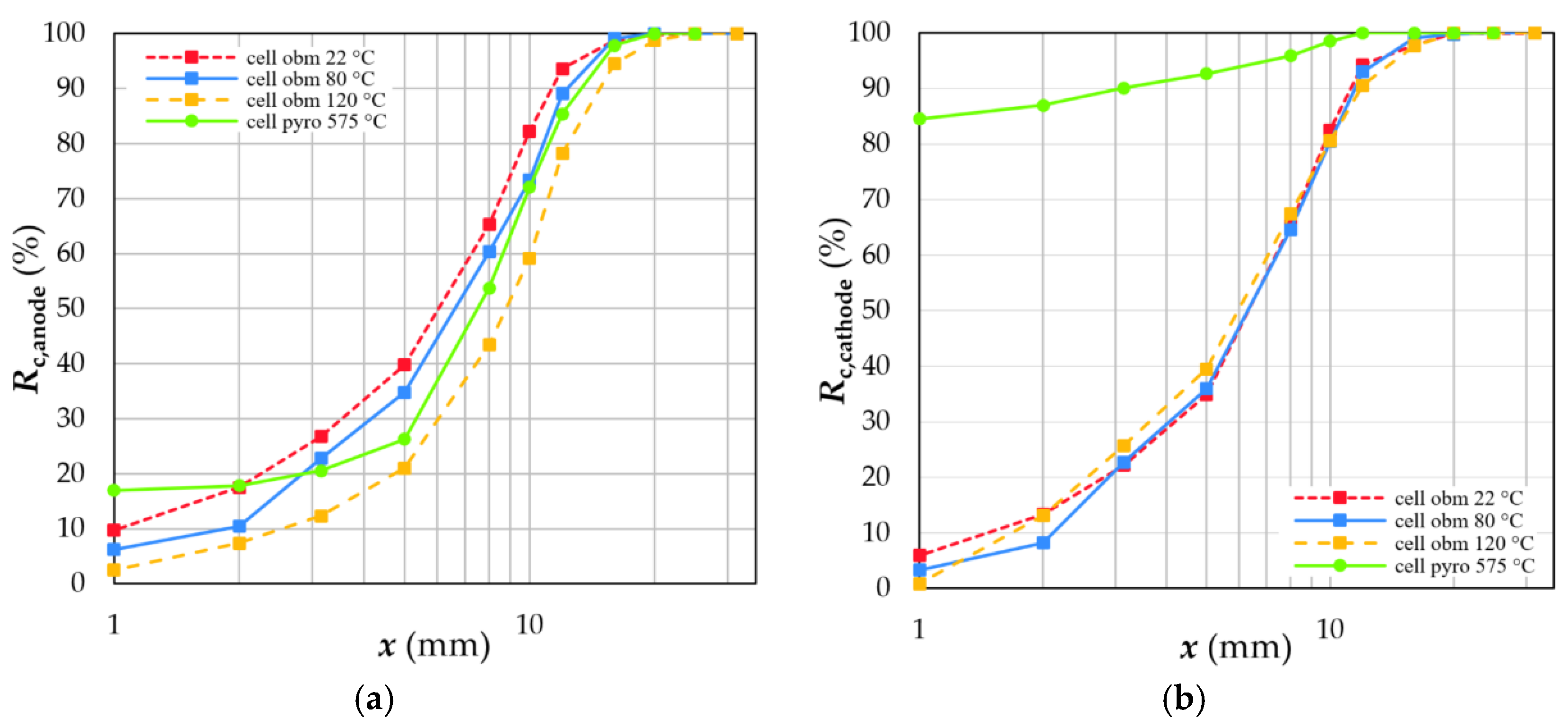
Figure 13 and Figure 14 show the fragment size distributions of pyrolized cells as well as manually dismantled electrodes of different dismantling depths. For pyrolized cells, a relatively high amount of fines are generated as a consequence of the changed breakage behaviour of the electrodes (see also Section 4.2). Pyrolysis creates holes of different sizes in the Al foils of the cathode due to pitting corrosion [79]. Furthermore, decoating is immensely enhanced (see Section 4.3).
In contrast, decoating of the anodes is only increased slightly due to a more brittle material behavior. The anode recovery of cells with an open burst membrane shows coarser particles with increasing depollution temperature, whereas the cathode recovery is independent of the depollution temperature. This effect correlates with the comparable influence of temperature on the degree of decoating for both electrodes (see Section 4.3). Due to the compact nature of cells with open burst membrane, the oxidization of the Al foils is reduced at lower temperatures, leading to a much lower pitting corrosion. In contrast, the thermal depollution changes the breaking behavior of the anodes; thus, their fragments ultimately become even coarser.
For manually dismantled windings or electrodes, the breakage behaviour of their anodes does not follow a clear trend in terms of depollution temperature (cf. Figure 14a,b). Depending on the feed material, the amount of fines and the upper fragment size are very similar and independent of the depollution temperature. The differences between windings and electrodes as feed derive from the presence of separator foil during the crushing of windings. The separator is much harder to cut due to its elastic material behavior but blocks the grid openings. Therefore, the fragments of the electrode foils remain longer in the milling chamber, being cut down to finer sizes. The fluctuations of the median value of windings, as well as anodes at different depollution temperatures, is caused by random blocking of the grid openings and not fully understand yet.
Comparing the feed of windings and/or electrodes with non-dismantled battery cells, the effect of the housing materials becomes obvious (cf. Figure 13). The housing consists mainly of thick-walled Al sheets, which are crushed into robust flat metal pieces with sharp edges. These pieces accelerate the removal of electrode fragments from the crushing chamber through the grid openings, leading to a coarser fragment size distribution of the electrodes.

4.4.3. Coating Material and Remaining Compounds

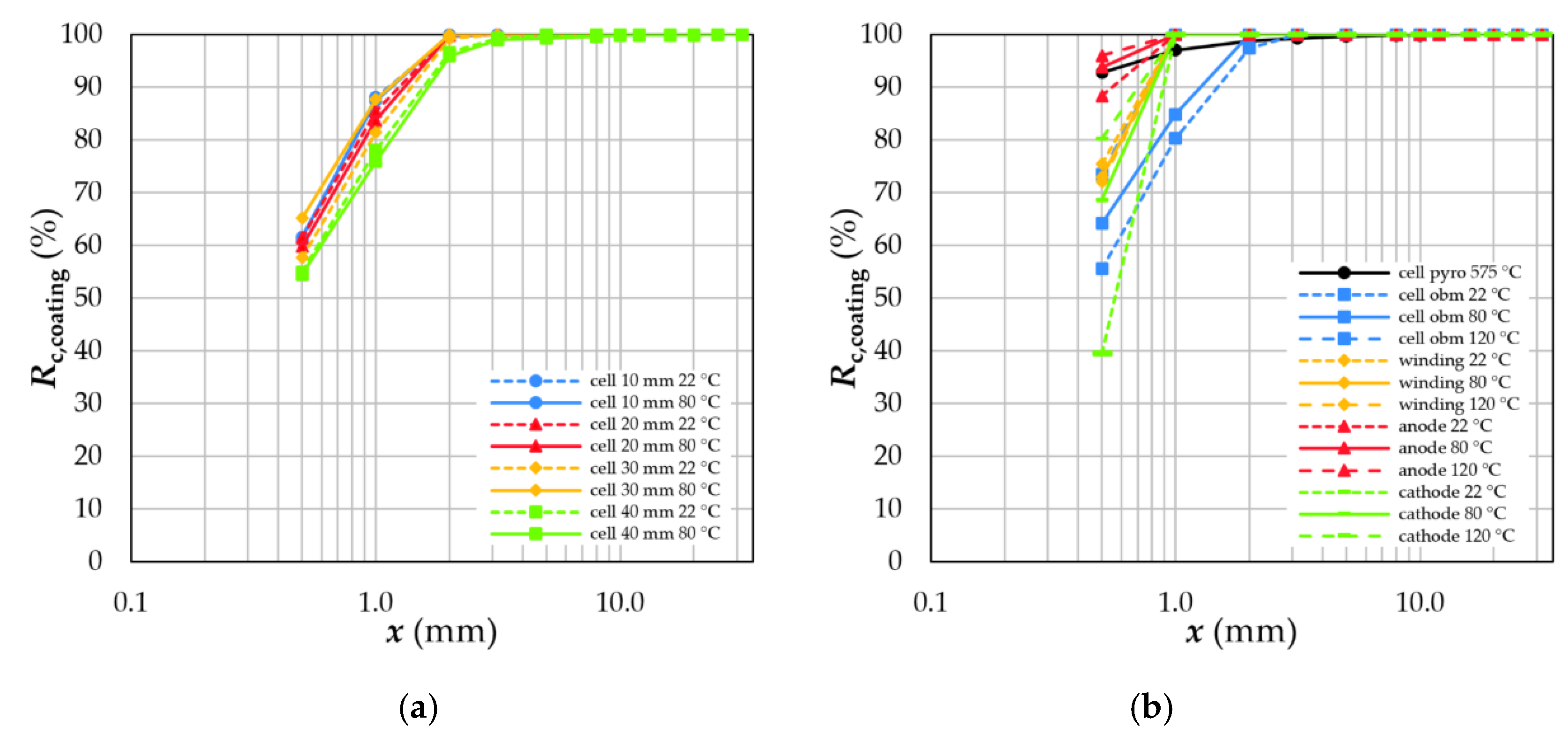
The coating materials are about 51.9% of the whole battery cell (see Section 3.1). After crushing, the materials are found exclusively in size fractions lower than 3.15 mm, independent of depollution and drying temperature as well as crushing parameters (cf. Figure 15a). However, the shape of the coating particles differs in the individual setups due to changing decoating mechanisms. The coating fragments in the size fractions above 1 mm are platy ablations, whereas below 1 mm, they are more cubical or even spherical. A prolonged residence time in the cutting chamber and an increased number of stress events due to smaller grid sizes in the final crushing break the initially plate-like fragments into more cubical ones. However, the influences of grid size and, thus, specific energy input (cf. Figure 4) seem negligible regarding the size reduction of untreated battery cells (cf. Figure 15b). The fragment size distributions shift just slightly towards finer sizes with decreasing grid size.
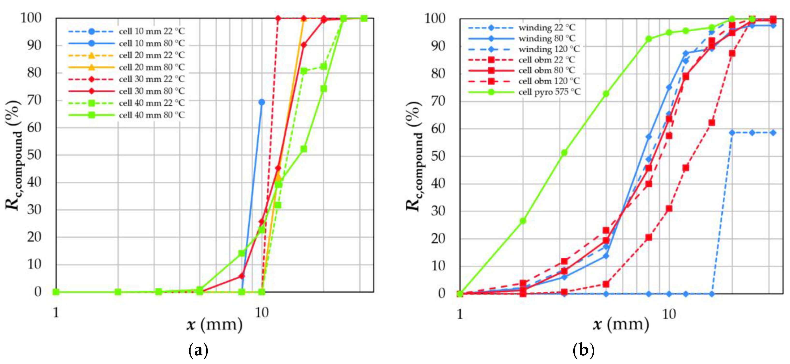
Regarding thermally treated cells or cell components, the amount of fines < 0.5 mm increases with increasing temperatures (cf. Figure 15a). Pyrolized cells and anodes show a fine coating fraction of at least 88.4%, whereas cathode coating reaches 80% at the maximum, respectively. If the batteries are dismantled down to the windings, the temperature has no effect on the coating recovery. However, the overall mass recovery shifts towards finer size fractions with rising depollution temperature, as shown in Section 4.2. After crushing, an amount of 1.1% of compounds remains in the crushing product (cf. Figure 16a). They are recovered mainly in the size fractions above 5 mm due to a too-low residence time in the cutting chamber and insufficient liberation (see Section 4.3). After thermal treatment, the amount of compounds is increased to 15.0%. Additionally, the compound fragments are finer (cf. Figure 16b). Temperatures of 80 °C and 120 °C merge parts of the battery components, and liberation is not possible during cutting.

5. Conclusions

A worldwide trend toward the mechanical processing of EOL LIBs is recognisable due to upcoming legal regulations in the direction of increasing mass-based and material-based recycling efficiencies. The present study illustrates the complex interrelations of dismantling depth, thermal depollution and product quality within the pretreatment and mechanical processing of prismatic LIB cells. The main conclusions regarding EOL LIB recycling can be summarized as follows:
  • After crushing in a cutting mill with grid sizes between 10 and 40 mm, fragments accumulate mainly in size fractions >1.0 mm. The finer size fractions <1.0 mm consists mainly of coating materials (see also [33,39,80]). Higher dismantling depths decrease the complexity of the feed compound, which has to be liberated by subsequent crushing steps.
  • Elevated temperatures for depollution rearrange the crystal structure of the binder used for electrode coatings or even decompose them completely. Moreover, high temperatures weaken the tensile strength and stability of the plastics used as separator foils in LIBs. Consequently, compounds are formed, and electrode decoating is reduced to recoveries of less than 20%.
  • The specific energy input necessary to crush a battery cell can be estimated by examining the crushing behaviour of its individual components. However, liberation and decoating cannot be predicted with this approach. In general, the energy input decreases with increasing grid size, increasing dismantling depth and depollution temperature.
  • Thermal depollution between 80 °C and 120 °C partly removes organic solvents. Unfortunately, thermal depollution above the operating temperature of 60 °C is disadvantageous for subsequent separation steps due to the formation of compounds and a deteriorating decoating.
  • Sieving can be used to separate a coating fraction since all other battery components are enriched in the coarser size classes. The mass recovery and quality of this fraction (black mass) is influenced by the thermal treatment and grid size in the crushing device.
Altogether, further research must be carried out in the temperature range between 120 °C and 575 °C. Additionally, different pyrolysis conditions must be studied to understand the complex chemical reactions between the different materials in detail. A special focus must be put on the complete decomposition of the binders, the reduction of composite generation as well as the corrosion of aluminium, which might even positively affect the subsequent (physical) separation of the fine fraction (black mass) (see also [18,79,80].
Besides thermal depollution, the influence of the discharging method and depth on crushing, liberation and decoating behaviour also must be considered more closely. Furthermore, crushing and decoating kinetics, in general, must be investigated on the micro and macro scale. Altogether, such investigations are highly relevant to improving recycling processes and to increasing the AM recovery of black mass in general, as well as anode coating material in particular.

Author Contributions

Conceptualization, methodology, investigation, and writing—original draft preparation, D.M.W. and T.M.; writing—review and editing, D.M.W., T.M. and U.A.P.; supervision, T.M. and U.A.P.; project administration, U.A.P.; funding acquisition, U.A.P. All authors have read and agreed to the published version of the manuscript.

Funding

This research was funded by the Federal Ministry for Education and Research (BMBF), as well as the Projektträger Jülich (PTJ), within the project “Innovative Recyclingprozesse für neue Lithium-Zellgenerationen—Mechanische Prozesse” (InnoRec) Project No. 03XP0246C performed within the competence cluster for battery cell production (ProZell) as well as the project “Monitoring schwerflüchtiger Elektrolyte in der mechanischen Recyclingprozesskette” (LowVolMon) Project No. 03XP0354 performed within the competence cluster Recycling & Grüne Batterie (greenBatt).

Institutional Review Board Statement

Not applicable.

Informed Consent Statement

Not applicable.

Data Availability Statement

Not applicable.

Acknowledgments

The authors gratefully like to acknowledge BMW AG, which provided materials and information for the experimental part. Moreover, special thanks are sent to C. Stallmeister and the Institute of Metallurgy (IME), RWTH Aachen, for performing the pyrolysis. The authors would also like to thank the technical and scientific staff of the Institute of Mechanical Process Engineering and Mineral Processing for their ICP-OES measurements. The biggest thanks go to our student workers for their patience and endurance during the manual sorting of fragments after crushing, which felt never-ending.

Conflicts of Interest

The authors declare no conflict of interest.

Nomenclature

AMActive materials MnManganese
AlAluminiumNCALithium Nickel Cobalt Aluminium Oxide
CMCSodium Carboxymethyl CelluloseNiNickel
CoCobalt NMCLithium nickel manganese cobalt battery
CuCopper NSDNail Penetration Safety Device
DECDiethyl carbonatePCPropylene carbonates
DMCDimethyl carbonatePEPolyethylene
EOLEnd-of-lifePETPolyethylene terephthalate
ECEthylene carbonatePF5Phosphorus pentafluoride
EMCEthyl methyl carbonatePPPolypropylene
HFHydrofluoric acidPVdFPolyvinylidene fluoride
ICP-OESInductively coupled plasma optical emission spectrometryRERecycling efficiency
LCOLithium cobalt oxideRRSlow-rotating, two-shaft rotary shear with axial gap
LiLithiumRR Recovery rate
LIB(s)Lithium-ion battery(ies)RSSlow-rotating, two-shaft rotary shear without axial gap
LFPLithium iron phosphateSBRStyrene butadiene rubber
LiFLithium fluorideUGOne-shaft rotary shear with outlet grid final crushing
LiPF6Lithium hexafluorophosphateWEEEWaste electrical and electronic equipment
MRRMaterial recovery rates

References

  1. Swain, B. Recovery and recycling of lithium: A review. Sep. Purif. Technol. 2017, 172, 388–403. [Google Scholar] [CrossRef]
  2. Elwert, T.; Römer, F.; Schneider, K.; Hua, Q.; Buchert, M. Recycling of Batteries from Electric Vehicles. In Behaviour of Lithium-Ion Batteries in Electric Vehicles—Battery Health, Performance, Safety, and Cost; Pistoia, G., Liaw, B., Eds.; Springer International Publishing AG: Cham, Switzerland, 2018. [Google Scholar]
  3. Melin, H.E. The Lithium-Ion Battery End-of-Life Market—A Baseline Study; Circular Energy Storage: London, UK, 2019. [Google Scholar]
  4. Zhang, X.; Cao, H.; Xie, Y.; Ning, P.; An, H.; You, H.; Nawaz, F. A closed-loop process for recycling LiNi1/3Co1/3Mn1/3O2 from the cathode scraps of lithium-ion batteries: Process optimization and kinetics analysis. Sep. Purif. Technol. 2015, 150, 186–195. [Google Scholar] [CrossRef]
  5. Mossali, E.; Picone, N.; Gentilini, L.; Rodrìguez, O.; Perez, J.M.; Colledani, M. Lithium-ion batteries towards circular economy: A literature review of opportunities and issues of recycling treatments. J. Environ. Manag. 2020, 264, 110500. [Google Scholar] [CrossRef] [PubMed]
  6. Vezzini, A. Manufacturers, Materials and Recycling Technologies. In Lithium-Ion Batteries Advances and Applications; Pistoia, G., Ed.; Elsevier: Amsterdam, The Netherlands, 2014; pp. 529–551. [Google Scholar]
  7. Directive 2006/66/EC of the European Parliament and of the Council; European Union: Brussels, Belgium, 2006.
  8. Friedrich, B.; Träger, T.; Weyhe, R. Recyclingtechnologien am Beispiel Batterien. In Proceedings of the 25. Aachener Kolloquium Abfallwirtschaft, Forum M, Aachen, Germany, 29 November 2012. [Google Scholar]
  9. Regulation of the European Parliament and of the Council Concerning Batteries and Waste Batteries; European Commission: Brussels, Beglium, 2020; p. 130.
  10. Directive 2012/19/EU of the European Parliament and of the Council on Waste Electrical and Electronic Equipment (WEEE); European Commission: Brussels, Belgium, 2012; p. 34.
  11. Directive 2000/53/EC of the European Parliament and of the Council on End-Of Life Vehicles; L 269; European Commission: Brussels, Belgium, 2000; p. 8.
  12. Al-Thyabat, S.; Nakamura, T.; Shibata, E.; Iizuka, A. Adaptation of minerals processing operations for lithium-ion (LiBs) and nickel metal hydride (NiMH) batteries recycling: Critical review. Miner. Eng. 2013, 45, 4–17. [Google Scholar] [CrossRef]
  13. Dewulf, J.; Van der Vorst, G.; Denturck, K.; Van Langenhove, H.; Ghyoot, W.; Tytgat, J.; Vandeputte, K. Recycling rechargeable lithium ion batteries: Critical analysis of natural resource savings. Resour. Conserv. Recycl. 2010, 54, 229–234. [Google Scholar] [CrossRef]
  14. Zhao, S.; He, W.; Li, G. Recycling Technology and Principle of Spent Lithium-Ion Battery. In Recycling of Spent Lithium-Ion Batteries—Processing Methods and Environmental Impacts; An, L., Ed.; Springer Nature Switzerland AG: Cham, Switzerland, 2019; pp. 1–26. [Google Scholar] [CrossRef]
  15. Zhao, G. Resource Utilization and Harmless Treatment of Power Batteries. In Reuse and Recycling of Lithium-Ion Power Batteries; Zhao, G., Ed.; John Wiley & Sons: Hoboken, NJ, USA, 2017; pp. 335–378. [Google Scholar]
  16. Werner, D.; Peuker, U.A.; Mütze, T. Recycling Chain for Spent Lithium-Ion Batteries. Met.—Open Access Metall. J. 2020, 10, 316. [Google Scholar] [CrossRef] [Green Version]
  17. Hanisch, C.; Haselrieder, W.; Kwade, A. Recycling von Lithium-Ionen-Batterien—Das Projekt LithoRec. In Recycling und Rohstoffe; Thomé-Kozmienski, K.J., Goldmann, D., Eds.; TK Verlag: Neuruppin, Germany, 2012; Volume 5, pp. 691–698. [Google Scholar]
  18. Werner, D.M.; Mütze, T.; Kaas, A.; Peuker, U.A. Mechanical and physical processes of battery recycling. In Nano Technology for Battery Recycling, Remanufacturing, and Reusing; Siamak, F., Gupta, R.K., Yasin, T., Nguyen, T.A., Eds.; Elsevier: Amsterdam, The Netherlands, 2022; Volume 1, pp. 455–486. [Google Scholar]
  19. Werner, D.; Mütze, T.; Peuker, U.A. Influence of cell opening methods on organic solvent removal during pretreatment in lithium-ion battery recycling. Waste Manag. Res. 2021, 40, 1015–1026. [Google Scholar] [CrossRef]
  20. Werner, D.; Mütze, T.; Peuker, U.A. Influence of cell opening methods organic solvent removal during processing in lithium-ion battery recycling. Metals 2022, 12, 663. [Google Scholar] [CrossRef]
  21. Stenzel, Y.P.; Börner, M.; Preibisch, Y.; Winter, M.; Nowak, S. Thermal profiling of lithium ion battery electrodes at different states of charge and aging conditions. J. Power Sources 2019, 433, 226709. [Google Scholar] [CrossRef]
  22. Chen, H.; Ling, M.; Hencz, L.; Ling, H.Y.; Li, G.; Lin, Z.; Liu, G.; Zhang, S. Exploring Chemical, Mechanical, and Electrical Functionalities of Binders for Advanced Energy-Storage Devices. Chem. Rev. 2018, 118, 8936–8982. [Google Scholar] [CrossRef]
  23. Jeschull, F.; Brandell, D.; Wohlfahrt-Mehrens, M.; Memm, M. Water-Soluble Binders for Lithium-Ion Battery Graphite Electrodes: Slurry Rheology, Coating Adhesion, and Electrochemical Performance. Energy Technol. 2017, 5, 2108–2118. [Google Scholar] [CrossRef]
  24. Wang, X.; Gaustad, G.; Babbitt, C.W.; Bailey, C.; Ganter, M.J.; Landi, B.J. Economic and environmental characterization of an evolving Li-ion battery waste stream. J. Environ. Manag. 2014, 135, 126–134. [Google Scholar] [CrossRef]
  25. Cholewinski, A.; Si, P.; Uceda, M.; Pope, M.; Zhao, B. Polymer Binders: Characterization and Development toward Aqueous Electrode Fabrication for Sustainability. Polymers 2021, 13, 631. [Google Scholar] [CrossRef]
  26. Vuorilehto, K. Materials and functions. In Lithium-Ion Batteries: Basics and Applications; Korthauer, R., Ed.; Springer: Berlin/Heidelberg Germany, 2019; Volume 2, pp. 21–28. [Google Scholar] [CrossRef]
  27. Kwade, A.; Haselrieder, W.; Leithoff, R.; Modlinger, A.; Dietrich, F.; Droeder, K. Current status and challenges for automotive battery production technologies. Nat. Energy 2018, 3, 290–300. [Google Scholar] [CrossRef]
  28. Korthauer, R. (Ed.) Handbuch Lithium-Ionen-Batterien; Springer Vieweg: Berlin/Heidelberg, Germany, 2013. [Google Scholar]
  29. Kwade, A.; Diekmann, J. (Eds.) Recycling of Lithium-Ion Batteries—The LithoRec Way; Springer: New York, NY, USA, 2018. [Google Scholar]
  30. Arnberger, A.; Gresslehner, K.-H.; Pomberger, R.; Curtis, A. Recycling von Lithium Ionen Batterien aus EVs & HEVs. In Proceedings of the DepoTech 2012, Leoben, Austria, 6–9 November 2012. [Google Scholar]
  31. Gaines, L.; Sullivan, J.; Burnham, A. Life-Cycle Analysis for Lithium-Ion Battery Production and Recycling. In Proceedings of the 90th Annual Meeting of the Transportation Research Board, Washington, DC, USA, 23–27 January 2011. [Google Scholar]
  32. Georgi-Maschler, T.; Friedrich, B.; Weyhe, R.; Heegn, H.; Rutzc, M. Development of a recycling process for Li-ion batteries. J. Power Sources 2012, 207, 173–182. [Google Scholar] [CrossRef]
  33. Wang, X.; Gaustad, G.; Babbitt, C.W. Targeting high value metals in lithium-ion battery recycling via shredding and size-based separation. Waste Manag. 2016, 51, 204–213. [Google Scholar] [CrossRef] [Green Version]
  34. Arnberger, A.; Coskun, E.; Rutrecht, B. Recycling von Lithium-Ionen-Batterien. In Recycling und Rohstoffe; Thomé-Kozmiensky, K.J., Goldmann, D., Eds.; TK Verlag Karl Thomé-Kozmiensky: Neuruppin, Germany, 2018; Volume 11, pp. 583–599. [Google Scholar]
  35. Friedrich, B.; Schwich, L. E-Mobility Batteries Recycling—How to Reach the Demanded Recycling Efficiency? In Proceedings of the VDMA Webinar, online, 22 June 2021. [Google Scholar]
  36. Rahimzei, E. Begleit- und Wirkungsforschung Schaufenster Elektromobilität (BuW) Ergebnispapier Nr. 37—Sicherheit von Elektrofahrzeugen; Deutsches Dialog Institut GmbH: Frankfurt am Main, Germany, 2017. [Google Scholar]
  37. Gama, M. European Li-Ion Battery Advanced Manufacturing For Electric Vehicles—ELIBAMA. 2014. Available online: https://cordis.europa.eu/project/id/285385 (accessed on 28 June 2022).
  38. Hanisch, C.; Diekmann, J.; Stieger, A.; Haselrieder, W.; Kwade, A. Recycling of Lithium-Ion Batteries. In Handbook of Clean Energy Systems; Yan, J., Cabeza, L.F., Sioshansi, R., Eds.; John Wiley & Sons, Ltd.: Hoboken, NJ, USA, 2015; Volume 5, pp. 2865–2888. [Google Scholar]
  39. Wuschke, L. Mechanische Aufbereitung von Lithium-Ionen-Batteriezellen. Ph.D. Thesis, TU Bergakademie Freiberg, Freiberg, Germany, 2018. [Google Scholar]
  40. Van Pels, W. Herausforderung hinsichtlich der Brandschutztechnologien in Recyclinganlagen insbesondere bei der Verarbeitung von Li-Ionen Traktionsbatterien. In Proceedings of the Recycling und Sekundärrohstoffe, Berlin, Germany, 2–3 March 2020; pp. 496–505. [Google Scholar]
  41. Wegener, K.; Andrew, S.; Raatz, A.; Dröder, K.; Herrmann, C. Disassembly of Electric Vehicle Batteries Using the Example of the Audi Q5 Hybrid System. In Proceedings of the Conference on Assembly Technologies and Systems, Dresden, Germany, 15–16 May 2014. [Google Scholar]
  42. Ekberg, C.; Petranikova, M. Lithium Batteries Recycling. In Lithium Process Chemistry—Resources, Extraction, Batteries and Recycling; Chagnes, A., Swiatowska, J., Eds.; Elsevier: Amsterdam, The Netherlands, 2015; pp. 233–269. [Google Scholar] [CrossRef]
  43. Martens, H.; Goldmann, G. (Eds.) Recyclingtechnik; Springer Vieweg: Wiesbaden, Germany, 2016. [Google Scholar]
  44. Pinegar, H.; Smith, Y.R. Recycling of End-of-Life Lithium-Ion Batteries, Part II: Laboratory-Scale Research Developments in Mechanical, Thermal, and Leaching Treatments. J. Sustain. Metall. 2020, 6, 142–160. [Google Scholar] [CrossRef]
  45. Liu, W.; Zhong, X.; Han, J.; Qin, W.; Liu, T.; Zhao, C.; Chang, Z. Kinetic Study and Pyrolysis Behaviors of Spent LiFePO4 Batteries. ACS Sustain. Chem. Eng. 2019, 7, 1289–1299. [Google Scholar] [CrossRef]
  46. Träger, T.; Friedrich, B.; Weyhe, R. Recovery Concept of Value Metals from Automotive Lithium-Ion Batteries. Chem. Ing. Tech. 2015, 87, 1550–1557. [Google Scholar] [CrossRef]
  47. Lombardo, G.; Ebin, B.; Steenari, B.-M.; Alemrajabi, M.; Karlsson, I.; Petranikova, M. Comparison of the effects of incineration, vacuum pyrolysis and dynamic pyrolysis on the composition of NMC-lithium battery cathode-material production scraps and separation of the current collector. Resour. Conserv. Recycl. 2021, 164, 105142. [Google Scholar] [CrossRef]
  48. Rahimzei, E. Transportation of lithium batteries and lithium-ion batteries. In Lithium-Ion Batteries: Basics and Applications; Korthauer, R., Ed.; Springer: Berlin/Heidelberg, Germany, 2019. [Google Scholar] [CrossRef]
  49. Park, Y.-S.; Oh, E.-S.; Lee, S.-M. Effect of polymeric binder type on the thermal stability and tolerance to roll-pressing of spherical natural graphite anodes for Li-ion batteries. J. Power Sources 2014, 248, 1191–1196. [Google Scholar] [CrossRef]
  50. Hanisch, C.; Loellhoeffel, T.; Diekmann, J.; Markley, K.J.; Haselrieder, W.; Kwade, A. Recycling of lithium-ion batteries: A novel method to separate coating and foil of electrodes. J. Clean. Prod. 2015, 108, 301–311. [Google Scholar] [CrossRef]
  51. Xie, L.; Zhao, L.; Wan, J.-L.; Shao, Z.-Q.; Wang, F.-J.; Lv, S.-Y. The Electrochemical Performance of Carboxymethyl Cellulose Lithium as a Binding Material for Anthraquinone Cathodes in Lithium Batteries. J. Electrochem. Soc. 2012, 159, A499–A505. [Google Scholar] [CrossRef]
  52. Sun, X.; Zhang, X.; Zhang, H.; Huang, B.; Ma, Y. Application of a novel binder for activated carbon-based electrical double layer capacitors with nonaqueous electrolytes. J. Solid State Electrochem. 2013, 17, 2035–2042. [Google Scholar] [CrossRef]
  53. Orendorff, C.J. The Role of Separators in Lithium-Ion Cell Safety. Electrochem. Soc. Interface 2012, 21, 61–65. [Google Scholar] [CrossRef]
  54. Weber, C.J.; Roth, M. Separators. In Lithium-Ion Batteries: Basics and Applications; Korthauer, R., Ed.; Springer: Berlin/Heidelberg, Germany, 2019; pp. 75–88. [Google Scholar] [CrossRef]
  55. Zhong, X.; Liu, W.; Han, J.; Jiao, F.; Qin, W.; Liu, T.; Zhao, C. Pyrolysis and physical separation for the recovery of spent LiFePO4 batteries. Waste Manag. 2019, 89, 83–89. [Google Scholar] [CrossRef] [PubMed]
  56. Tomaszewska, K.; Kaluzna-Czapliñska, J.; Józwiak, W.K. Thermal and thermo-catalytic degradation of polyolefins as a simple and efficient method of landfill clearing. Pol. J. Chem. Technol. 2010, 12, 50–57. [Google Scholar] [CrossRef] [Green Version]
  57. Onu, P.; Vasile, C.; Ciocılteu, S.; Iojoiu, E.; Darie, H. Thermal and catalytic decomposition of polyethylene and polypropylene. J. Anal. Appl. Pyrolysis 1999, 49, 145–153. [Google Scholar] [CrossRef]
  58. Kim, J.; Gil Lee, J.; Kim, H.S.; Lee, T.J.; Park, H.; Ryu, J.H.; Oha, S.M. Thermal Degradation of Solid Electrolyte Interphase (SEI) Layers by Phosphorus Pentafluoride (PF5) Attack. J. Electrochem. Soc. 2017, 164, A2418–A2425. [Google Scholar] [CrossRef]
  59. Hartnig, C.; Schmidt, M. Elektrolytes and conducting salts. In Lithium-Ion Batteries: Basics and Applications; Korthauer, R., Ed.; Springer: Berlin/Heidelberg, Germany, 2019; Volume 2, pp. 59–74. [Google Scholar] [CrossRef]
  60. Haselrieder, W.; Westphal, B.; Bockholt, H.; Diener, A.; Höft, S.; Kwade, A. Measuring the coating adhesion strength of electrodes for lithium-ion batteries. Int. J. Adhes. Adhes. 2015, 60, 1–8. [Google Scholar] [CrossRef]
  61. Pielichowski, K.; Njuguna, J. Thermal Degradation of Polymeric Materials; Rapra Technology Limited: Shawbury, Shrewsbury, Shropshire, UK, 2005. [Google Scholar]
  62. Wendler-Kalsch, E.; Gräfen, H. Korrosionsschadenkunde; Springer: Berlin/Heidelberg, Germany, 1998. [Google Scholar]
  63. Kaesche, H. Die Korrosion der Metalle—Physikalisch-chemische Prinzipien und aktuelle Probleme, 3rd ed.; Springer: Berlin/Heidelberg, Germany, 2011. [Google Scholar]
  64. Ostermann, F. Korrosion. In Anwendungstechnologie Aluminium; Ostermann, F., Ed.; Springer Vieweg: Berlin/Heidelberg, Germany, 2014; Volume 3, pp. 217–270. [Google Scholar]
  65. Sander, S.; Schubert, G.; Timmel, G. Characterisation of fragments produced by the comminution of metals especially considering the fragment shape. Powder Technol. 2002, 122, 177–187. [Google Scholar] [CrossRef]
  66. Woldt, D. Zerkleinerung nicht-spröder Stoffe in Rotorscheren und -reißern. Ph.D. Thesis, TU Bergakademie Freiberg, Freiberg, Germany, 2004. [Google Scholar]
  67. Timmel, G.; Sander, S.; Schubert, G. Comminution of scrap and metals in shredders with horizontally and vertically mounted rotor. Dev. Miner. Process. 2000, 13, C12a-11–C12a-18. [Google Scholar]
  68. Schubert, G. Comminution Equipment for Non-Brittle Waste and Scrap. Aufbereitungstechnik 2002, 43, 6–23. [Google Scholar]
  69. Despotopoulou, M.; Burchill, M.T. Coatings for electrochemical applications. Prog. Org. Coat. 2002, 45, 119–126. [Google Scholar] [CrossRef]
  70. He, L.-P.; Sun, S.-Y.; Song, X.-F.; Yu, J.-G. Recovery of cathode materials and Al from spent lithium-ion batteries by ultrasonic cleaning. Waste Manag. 2015, 46, 523–528. [Google Scholar] [CrossRef]
  71. Shin, S.M.; Kim, N.H.; Sohn, J.S.; Yang, D.H.; Kim, Y.H. Development of a metal recovery process from Li-ion battery wastes. Hydrometallurgy 2005, 79, 172–181. [Google Scholar] [CrossRef]
  72. Wuschke, L.; Jäckel, H.-G.; Leißner, L.; Peuker, U.A. Crushing of large Li-ion battery cells. Waste Manag. 2019, 85, 317–326. [Google Scholar] [CrossRef]
  73. Pinegar, H.; Smith, Y.R. End-of-Life Lithium-Ion Battery Component Mechanical Liberation and Separation. J. Miner. Met. Mater. Soc. 2019, 71, 4447–4456. [Google Scholar] [CrossRef]
  74. Schwarz, T.E.; Rübenbauer, W.; Rutrecht, B.; Pomberger, R. Forecasting Real Disassembly Time of Industrial Batteries based on Virtual MTM-UAS Data. In Proceedings of the 25th CIRP Life Cycle Engineering (LCE) Conference, Copenhagen, Denmark, 30 April–2 May 2018; pp. 927–931. [Google Scholar]
  75. Wuschke, L.; Jäckel, H.-G.; Gellner, M.; Peuker, U.A. Comminution of Li-Ion Traction Batteries. In Proceedings of the European Symposium on Comminution and Classification, Gothenborg, Sweden, 7–11 September 2015; p. 6. [Google Scholar]
  76. Woldt, D.; Schubert, G.; Jäckel, H.-G. Size reduction by means of low-speed rotary shears. Int. J. Miner. Process. 2004, 74, 405–415. [Google Scholar] [CrossRef]
  77. Schubert, G. Aufbereitung metallischer Sekundärrohstoffe—Aufkommen Charakterisierung Zerkleinerung; Springer: Wien, Austria, 2012. [Google Scholar]
  78. Hanisch, C.; Schünemann, J.-H.; Diekmann, J.; Westphal, B.; Loellhoeffel, T.; Prziwara, P.; Haselrieder, W.; Kwade, A. In-Production Recycling of Active Materials from Lithium-Ion Battery Scraps. ECS Trans. 2015, 64, 131–145. [Google Scholar] [CrossRef]
  79. Vanderbruggen, A.; Hayagan, N.; Bachmann, K.; Ferreira, A.; Werner, D.M.; Horn, D.; Peuker, U.A.; Serna-Guerrero, R.; Rudolph, M. Lithium-Ion Battery Recycling—Influence of Recycling Processes on Component Liberation and Flotation Separation Efficiency. ACS EST Eng. 2022. [Google Scholar] [CrossRef]
  80. Gellner, M. Mechanische Aufbereitung der Feinfraktion Zerkleinerter Lithium-Ionen-Batterien. Ph.D. Thesis, TU Bergakademie Freiberg, Freiberg, Germany, 2018. [Google Scholar]
Figure 1. Dismantling steps: (a) system with 8 modules (red); (b) module with 12 cells (red) and bursting membrane (green); (c) functional unit with open-bended cell housing (top row) containing 4 windings (bottom row); (d) Top row from left: cathode and anode; bottom row: separator and housing [19].
Metals 12 01839 g001
Figure 2. Flow chart of experimental setup (RR: two-shaft rotary shear with axial gap, RS: two-shaft rotary shear without axial gap, UG: cutting mill with outlet grid, cell obm: cell with open bursting membrane; cell pyro: pyrolyzed cell).
Metals 12 01839 g002
Figure 3. (a) Schematic of a slow-rotating, two-shaft machine (RR/RS); (b) schematic of a fast-rotating, one-shaft rotary shear (UG) [20].
Metals 12 01839 g003
Figure 4. Mass-specific energy input for materials of different dismantling depths (cell, pyrolyzed cells (cell pyro), cells with open bursting membrane (cell obm), housing, winding, anode and cathode), depollution temperatures and crushing setups (precrushing: RR (and/or RS); final crushing: UG with respective grid openings).
Metals 12 01839 g004
Figure 5. Calculated specific energy input for different depollution temperatures and dismantling depths compared to the measured specific energy input of cells with open bursting membrane.
Metals 12 01839 g005
Figure 6. Fragment size distributions of cells after final crushing at different grid sizes and drying (a); comparison of pyrolyzed cells (cell pyro) and cells with an open bursting membrane (cell obm) crushed at 30 mm grid size (b).
Metals 12 01839 g006
Figure 7. Fragment size distributions of housing, windings (a), and electrodes (b) for different depollution temperatures crushed at 30 mm grid size.
Metals 12 01839 g007
Figure 8. Degree of liberation A and degree of decoating AD for cells at different grid sizes (a) and for pyrolyzed cells (Td = 575 °C) and cells with open burst membrane (Td = 22 … 120 °C) (b).
Metals 12 01839 g008
Figure 9. Degree of liberation A and degree of decoating AD for thermal depolluted windings (a) and electrodes (b).
Metals 12 01839 g009
Figure 10. Recovery of separator foil for cells at different UG grid sizes and drying temperatures (a) and for pyrolized cells (cell pyro), cells with open burst membrane (cell obm) and windings crushed at 30 mm grid size (b).
Metals 12 01839 g010
Figure 11. Recovery of housing for cells at different UG grid sizes and drying temperatures (a) and for pyrolized cells (cell pyro) and cells with open burst membrane (cell obm) crushed at 30 mm grid size (b).
Metals 12 01839 g011
Figure 12. Recovery of anodes (a) and cathodes (b) for cells at different grid sizes and drying temperatures.
Metals 12 01839 g012
Figure 13. Recovery of anodes (a) and cathodes (b) for pyrolized cells (cell pyro) and cells with open burst membrane (cell obm) crushed at 30 mm grid size.
Metals 12 01839 g013
Figure 14. Recovery of anodes (a) and cathodes (b) for windings and electrodes crushed at 30 mm grid size.
Metals 12 01839 g014
Figure 15. Recovery of coating for cells with different grid sizes and drying temperature (a) and for pyrolized cells (cell pyro), cells with open burst membrane (cell obm), windings and electrodes crushed at 30 mm grid size (b).
Metals 12 01839 g015
Figure 16. Recovery of compounds for cells at different grid sizes and drying temperatures (a) and for pyrolized cells (cell pyro), cells with open burst membrane (cell obm), and windings crushed at 30 mm grid size (b).
Metals 12 01839 g016
Table 1. Material specific temperatures according to [49] 1, [21] 2, [50] 3, [51] 4, [52] 5, [53] 6, [54] 7, [55] 8, [56] 9, [57] 10, [58] 11 and [59] 12.
ComponentBinder Type/
Material
Thermal Stability/
Melting Point
T in °C
Decomposition/Degradation Temperature T in °CAdhesive Strength
Optimum/Shrinkage T in °C
PristineCycled
anodeSBRpermanent: 70350–450 2400 1300 3
short-term: 120 1
CMCstable 4,5250–300 1230 1, 247 4,5-
Cu1085---
cathodePVdF185 5450 2410 1, 415 4400 3
Al660---
separatorPE130–135 6,7165 8,9
200 10
-110 6
PP160–165 6120 6
conducting saltLiPF660 11-70 11,12-
Table 2. Cell composition of the test material [19].
ComponentFunctionMaterialMass Share w (%)
cathodemetal foilAl3.0
coatingNMC + PVdF + additives34.0
anodemetal foilCu7.2
coatinggraphite + SBR + CMC + additives17.9
housingNSD contactCu0.9
electrical contactCu0.7
electrical contactAl0.3
caseAl11.8
retainerPP0.7
sleevePET0.3
NSD foilPP0.1
foilsPP0.2
glueunknown0.2
othersnot specified0.5
separatorfoilPP/PE/PP1.9
electrolyteorganic solventsDMC16.8
EMC
DEC
EC
conductive saltLiPF62.6
additivesunknown1.0
Table 3. Relative mass and mean specific energy input of the individual components used for the calculation of separator’s energy input at different depollution temperatures TD.
ComponentMean Specific
Energy Input
Dismantling DepthTd in °C
Relative Mass2280120
housingwm,j in kWh/t-15.214.814.1
wj in %functional unit16.117.217.7
electrodes17.518.118.3
windingwm,j in kWh/t-1.51.51.0
wj in %functional unit83.982.882.3
anodewm,j in kWh/t-0.80.30.6
wj in %functional unit34.233.233.0
electrodes41.540.540.4
cathodewm,j in kWh/t-0.30.40.2
wj in %functional unit44.745.645.7
electrodes54.155.655.9
separatorwm,j in kWh/t-23.729.217.6
wj in %functional unit3.63.23.0
electrodes4.43.93.7
Publisher’s Note: MDPI stays neutral with regard to jurisdictional claims in published maps and institutional affiliations.