Abstract
The work hardening behavior of α + θ UFG steel related to α + θ two phase microstructure is more complicated than that of single-phase materials. Very few studies have been conducted on the work hardening of α + θ UFG steels. Therefore, it is necessary to study the correlation between the work hardening and α + θ microstructure. In this study, the work hardening behavior of low-carbon ultrafine grain (UFG) steels with different grain size of ferrite and cementite particles, fabricated by rolling and annealing process, was studied. The α grain size was decreased to 132 ± 11 and 200 ± 19 nm in specimens cryorolled and annealed at 450 and 550 °C, which were smaller than that in specimen cold-rolled and annealed at 550 °C. However, the specimen cryorolled and annealed at 550 °C had a tensile strength of 740.3 MPa, which was lower than that in the other specimens. Results indicate that the work hardening is affected by ferrite and cementite in the UFG steels. The relatively coarse ferrite phase and the large number of fine intragranular cementite particles contribute to better work hardening. The intragranular cementite particles play a significant role in the improvement of work hardening, because the geometrically necessary dislocations are apt to form and store around intragranular cementite particles, while the intergranular cementite particles result in the decreased dislocation accumulation ability of ferrite and impair the strength of grain boundaries and work hardening of ferrite + cementite ultrafine grain steels.
1. Introduction
Grain refinement is one of the most effective ways to increase the strength of steels by concurrently maintaining toughness, with less alloy addition [1,2]. Ultrafine grain (UFG) steels have been a central topic in the development of a new generation of high-strength steels in recent decades [3,4,5]. Different initial microstructures, such as bainite, austenite, martensite, pearlite and ferrite were used to fabricate the UFG steels [6,7,8,9,10]. Various rolling processes and quenching routes were put forward to further refine the grain size and improve the mechanical properties [11,12].
It has been reported that the yield strength increases with the decrease in grain size, while the uniform tensile elongation of UFG steels greatly decreases, along with a sharply increased yield to tensile strength ratio (termed as the yield ratio) [13], because of early plastic instability. A drastic increase in the yielding-to-tensile ratio is also observed in UFG pure aluminium (Al), copper (Cu) and other nonferrous alloys [14,15,16]. Predictably, the high yield-to-tensile strength ratio will limit the application of UFG materials as structural material to a large extent. Two microstructure design strategies are proposed to optimize the relationship between tensile strength and yield-to-tensile strength ratio in the UFG steels. One strategy is the fabrication of single phase UFG steel with bimodal grain size, in which the nano- or submicron-scale grains provide the strength, and the micron grains improve the work hardening and plastic deformation ability [17]. Another method is to produce multiphase microstructures consisting of ferrite (α phase) and a strengthening phase such as θ-cementite, bainite, martensite or austenite [18,19]. The two-phase microstructure α + θ is popular for improving the strength and ductility of steel. However, the work hardening ability of α + θ UFG steels is still deficient compared to that of common structural materials. Understandably, it is important to further optimize the work hardening of α + θ UFG steels. However, most investigations concerning α + θ UFG steels focus on the optimization of fabrication technology, the microstructure evolution and tensile strength [20,21,22,23]; very few studies are conducted on the work hardening of α + θ UFG steels. The work hardening of α + θ UFG steels is different from that of single-phase materials and is related to α + θ two phase microstructures. Therefore, it is necessary to study the correlation between work hardening and α + θ microstructures.
An ultrafine microstructure with α + θ phase was fabricated by an equal channel angular pressing method in the study of K.T. Park et al., and results revealed that the work hardening, and uniform elongation increased with grain size [24]. T. Furehara et al. demonstrated that ultrafine steel with a α + θ phase was less likely to be a practical structural material, although its work hardening increased substantially compared to single-phase ultrafine steel [25]. Different microstructures with a α + θ phase in super-high carbon steel were made in the study of C.K. Syn et al., and the results demonstrate that the strength increased with the decreasing size of the α phase, while the work hardening was reduced [26]. The effects of α grain size on the work hardening of UFG steel were consecutively clarified, while quantitative discussion about the combined effects of a α + θ phase on the UFG steel was limited.
In the author’s previous studies, the low-carbon UFG steels, fabricated by different rolling temperatures and annealing processes, were reported [23]. In the present study, the reported UFG steels with representative different sizes of α grains and θ-cementite particles were used to clarify the role of θ-cementite on the mechanical behavior, especially in the work hardening. These supplementary results provide a theoretical foundation for the production of UFG steels with a better performance.
2. Materials and Methods
The Q235 steel, with a composition of Fe–0.165C–0.211Si–0.448Mn–0.014P–0.013S–0.002Als (wt %), was used as the test material. The experimental route to fabricate low-carbon UFG steel is shown in Figure 1. In the present study, two different rolling temperatures—cold rolling at room temperature and cryorolling at liquid nitrogen temperature (LNT)—were compared and discussed.
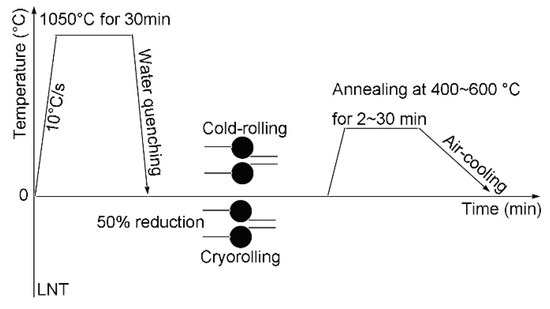
Figure 1.
Experimental route to fabricate low-carbon ultrafine grain steel.
The specimens were first austenitized at 1050 °C for 30 min, followed by water quenching to room temperature to obtain fully martensitic starting microstructure. Then, some specimens were directly cold rolled on a two-high mill with a roll diameter of 310 mm to 1.5 mm, in five passes at room temperature, by 50% reduction in thickness. Other quenched specimens were immersed in liquid nitrogen for 30 min to ensure uniform temperature. Then, the specimens were rapidly rolled to 1.5 mm in five passes. After rolling, all specimens were subsequently annealed between 400 and 600 °C for 2 to 30 min, then air cooled to room temperature. The annealing temperatures were selected by considering the theoretical recrystallization temperature of the tested steel and annealing temperatures for similar steels used by other studies and the authors’ previous studies [3,4,23,27,28,29].
All specimens were mounted, ground, and then polished for microstructure observation. The microstructure evolution of the specimens was observed along the rolling direction (RD) on a Nova 400 Nano scanning electron microscope (SEM), operated at an accelerating voltage of 20 kV. In addition, dislocation distribution before and after rolling was observed using a JEM-2100F transmission electron microscope (TEM). X-ray diffraction (XRD) tests were conducted to analyze phase evolution using filtered Co Ka radiation, operated at 35 kV and 50 mA. The grain size was measured using the mean linear intercept method (MLIM) and the dimension of Fe3C was measured using the chord-line method. Five images and more than 120 grains were measured to improve the accuracy. Tensile tests were carried out at room temperature with a cross-head speed of 1 mm min−1 on a UTM-4503 electronic universal tensile machine. The tensile direction was parallel to the rolling direction. The size of the gauge part of the tensile specimens was 1.2 mm wide, 0.6 mm thick, and 5 mm long. Duplicate tests were made for each tensile test to ensure reproducibility [30,31,32].
3. Results
3.1. Mechanical Property
Figure 2 presents the engineering stress-strain curves of representative specimens. The base steel Q235 was commercially available and the as-received tensile property is depicted in Figure 2 as a reference. All of the specimen that were cold-rolled and annealed at 550 °C for 30 min (termed as CR–550–30) had an excellent tensile strength (867.3 MPa) and elongation (16.8%). The tensile strength (970.2 Mpa) and elongation (12.3%) in the cryo-rolled specimen were obtained in the specimen annealed at 450 °C for 30 min (termed as Cryo–R–450–30), while the specimen cryorolled and annealed at 550 °C for 30 min (Cryo–R–550–30) had a tensile strength of 740.3 MPa and elongation of 16.7%.
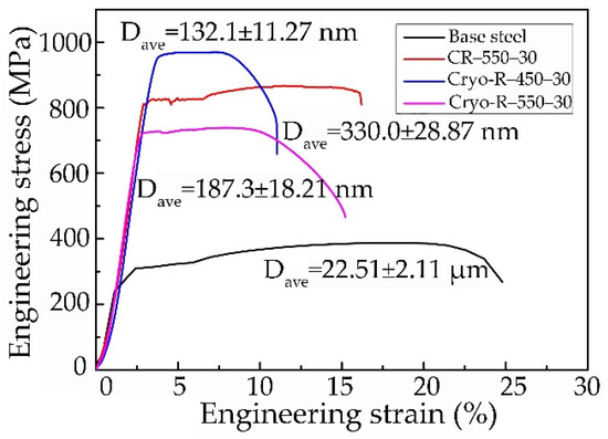
Figure 2.
Engineering stress-strain curves of representative specimens.
It was found that the tensile strength decreased with the drop of rolling temperature at the same annealing temperature of 550 °C for 30 min. This was primarily attributed to the increased grain size of the α phase and θ-cementite particles in the specimen Cryo–R–550–30, caused by the decreased complete recrystallization temperature of the α phase. Furthermore, it was clear that the tensile strength decreased with the increase in annealing temperature in the cryorolled specimens. This was because the recrystallization of the α phase was sufficient at 450 °C for 30 min, and some α grains tended to grow further at 550 °C.
3.2. Microstructure Evolution
Figure 3 shows one group of the quenched and rolled martensite microstructures. The lath martensite (1.97 μm in Figure 3a) was refined after cold rolling (1.26 μm in Figure 3b), whereas the martensite laths were further refined by cryorolling (0.21 μm in Figure 3c). The refined martensite laths with the decreased rolling temperature were caused by the increased deformation resistance at LNT. In addition, very clear dislocation areas were captured in the martensite laths. It was qualitatively found that the dislocation density in the cryorolling specimen was obviously larger than that in the cold rolling specimen. The dislocation densities of the three specimens were hard to estimate using TEM images, because the tangled dislocation line was difficult to observe, especially in the cryorolling specimens. However, it is well known that the dislocation density significantly increases after cold rolling, and further increases by cryorolling due to constricted recovery at low temperature [28].
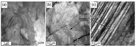
Figure 3.
TEM micrographs martensite morphologies of (a) quenched, (b) cold rolling of specimen CR-550-30, and (c) cryorolling of specimen Cryo–R–550–30.
The UFG microstructures of the above specimens are given in Figure 4 for comparison. Three different α phases were observed according to the number of θ-cementite particles within α grains. The first was a α phase without any intragranular θ particles (A1, Figure 4a), another contained a small amount (A2, Figure 4a), and the other a large amount (A3, Figure 4a), of intragranular θ particles, respectively. It was clear that the area fraction of the A1 α phase was the largest compared to the other two α phases. The diameter distributions of ultrafine α phases in the three specimens are presented in Figure 4d, which is based on several images. It was observed that the dominant size range of specimen CR–550–30 was 100~450 nm, while the grain sizes of 50~200 nm and 100~350 nm were the main distributions in the specimens of Cryo–R–450–30 and Cryo–R–550–30. The mean diameters of the α phase in the three specimens were measured to be 330 ± 30, 132 ± 11 and 200 ± 19 nm, respectively.
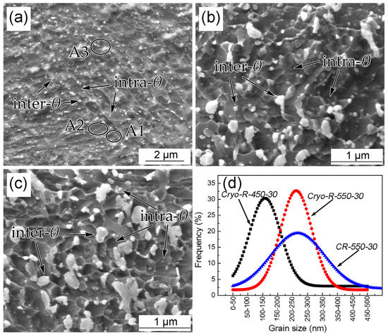
Figure 4.
SEM micrographs of α + θ phases in the specimens (a) CR–550–30, (b) Cryo–R–450–30 and (c) Cryo–R–550–30 and (d) corresponding size distribution of α grains.
The α and θ phases were further determined by means of the XRD method (Figure 5). This confirmed the results of our previous studies [23,27,28,29]. The widened {211} diffraction peaks (FWHM: CR–550–30 (0.562°) < Cryo–R–550–30 (0.628°) < Cryo–R–450–30 (0.884°)) in the XRD results (Figure 5) also revealed the decreased diameter of the α grains’ size in the cryo-rolled specimens. It was reasonable to choose the {211} peak for analysis of the ferrite lattice strain because it avoided the effects of the cementite peak and retains the relatively high intensity of the {211} peak [33]. The decreased size of the α grains by cryorolling treatment might be attributed to the two following reasons. Firstly, the decreased recrystallization finish temperature was caused by more distortion energy and the retention of defects at LNT. In addition, the dynamic recovery process containing the cross-slipping of screw dislocations and the climbing dislocations was restrained due to the extremely low temperature of LNT. Thus, more nucleation sites for the recrystallization of the α phase were provided. Secondly, the significantly reduced thickness of the lath martensite at LNT (Figure 3c) resulted in the refined α grains, after recrystallization.
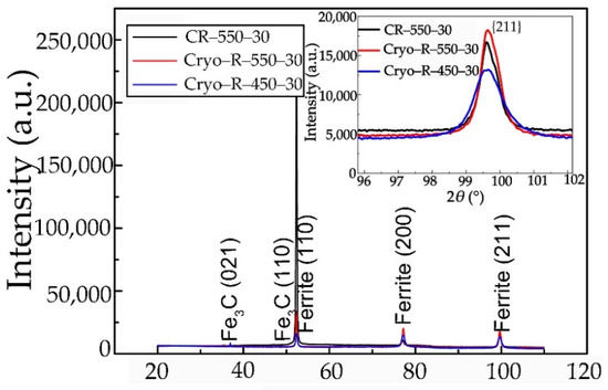
Figure 5.
The widened {211} diffraction peaks showing the decreased grain size in specimens cryorolled at LNT compared with specimen CR–550–30.
It is commonly believed that, based on the Hall-Petch relationship, yield strength increases with the decrease in grain size of α phase. However, it was interesting to find that the grain size of the α phase in specimen Cryo–R–550–30 was smaller than that of specimen CR–550–30, while the tensile strength and total elongation of specimen Cryo–R–550–30 were smaller than those of specimen CR–550–30. This inverted result might be caused by the distribution of the θ particles. Two types of θ particles, termed as intragranular and intergranular particles, were observed (Figure 4). The size of the intergranular θ particles was larger than that of the intragranular particles. This was because defects and alloy elements were easier to generate and accumulate at the grain boundaries. In addition, the free energy at the grain boundary was much higher than that within the grains, thus facilitating the further coarsening of the θ particle. It was found (Figure 4) that the coarsening was very serious for both the intragranular and intergranular particles in the cryorolled specimens, especially the latter. The coarsening of intragranular and intergranular particles in cryorolled specimens was attributed to the excessive diffusion of carbon atoms during the annealing process. The dislocation density and distortion energy in the cryo-rolled specimens were large. Almost no θ particles precipitate because of the adequately suppression of the diffusion of carbon atoms at LNT. Thus, the large dislocation density and distortion energy forced the carbon atoms into an unstable state. Consequently, the carbon atom’s motion was tremendously stimulated during the annealing process. Moreover, the higher interface energy in the ultrafine grains facilitated the growth of θ particles, especially for the cryo-rolled specimens with relatively smaller α grains.
The size comparison, according to the statistics of more than five images of the intragranular and intergranular θ particles in cold-rolled and cryorolled specimens, is shown in Figure 6. In three of the specimens, the size distribution of intragranular θ particles was ≤90 nm, while the main size range of intergranular θ particles was 30~120 nm. It was apparent that the size distributions of the intragranular θ particles in cryorolled specimens had little change, while the intragranular θ particles tended to be slightly smaller in the specimen CR–550–30. Nevertheless, relative conspicuous increase in the size of the intergranular θ particles was observed from specimen CR–550–30 to specimen Cryo–R–450–30, and then to specimen Cryo–R–550–30.
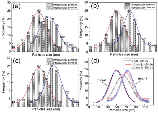
Figure 6.
Size distribution of the intragranular and intergranular θ particles in specimens (a) CR–550–30, (b) Cryo–R–450–30, (c) Cryo–R–550–30, and (d) comparison.
The results indicated that the intergranular θ particles had the worst thermostability and were much more sensitive to the processing route compared to the intragranular θ particles. Compared with specimen CR–550–30 (330 ± 30 nm), the relatively low tensile strength of specimen Cryo–R–550–30, with a mean grain size of 200 ± 19 nm, could be ascribed to the coarsening intragranular and intergranular particles, especially for the latter. These coarsened intergranular particles were more prone to generating the crack initiation during deformation and inducing the fracture. Furthermore, these intergranular particles superseded some grain boundaries and weakened their ability to accumulate dislocations and to facilitate crack propagation of the grain boundary.
Table 1 summarizes the grain parameters of the α + θ phases in three specimens, which were calculated based on the microstructures shown in Figure 4. The mean θ particle sizes of the above specimens were approximately 57.7, 100.2 and 121.4 nm, respectively. The total volume fractions of the θ particles were almost the same, due to having the same carbon content, while there were apparent changes in the allocation of the intragranular and intergranular θ particles. The volume fraction of the intergranular θ particles of the three specimens were always larger than those of the intragranular particles (finter-θ > fintra-θ). The fintra-θ decreased from specimen CR–550–30 (1.8%) to specimen Cryo–R–450–30 (1.3%), and then to specimen Cryo–R–550–30 (1.1%). The contrary tendency was observed from specimen CR–550–30 (5.1%) to specimen Cryo–R–450–30 (5.7%), and then to specimen Cryo–R–550–30 (5.9%) in the case of the finter-θ. According to the mean particle size (d) of the θ particles, the value of f/d was defined as the particle character parameter. It was concluded that the f/d parameter of the θ particles decreased from specimen CR–550–30 (0.12 %/nm) to specimen Cryo–R–450–30 (0.07 %/nm), and then to specimen Cryo–R–550–30 (0.06 %/nm).

Table 1.
Measured grain parameters of three specimens.
3.3. Work Hardening
Work hardening curves and Hollomon analysis of the aforementioned specimens are given in Figure 7. The large initial work hardening rates of four of the specimens can be interpreted by the shortened sliding distance of dislocation, which resulted from the ferrite segmentation by dislocation cell. However, the work hardening of UFG steels was generally inferior compared with the coarse grain steels as the counterpart. On the one hand, the dislocation accommodation ability of UFG is insufficient. On the other hand, increasing the grain boundary area in the per unit volume fraction of the UFG steel motivated the dynamic recovery and annihilation of the neighboring dislocations. The original steel had a good initial work hardening rate, but it was decreased sharply after exceeding a true strain value of 0.02. The worst work hardening rate in the original steel might be caused by the relatively large pearlite islands, or by the very small amount of the second phase, such as the θ particles in the ferrite grains. In opposition to the cryorolled specimens, with obviously decreased work hardening, the specimen CR–550–30 had the best work hardening. In addition, the work hardening decrease was spotted with the increase of the annealing temperature in the cryorolled specimens, although the grain size of the α phase in Cryo–R–550–30 was larger than that of specimen Cryo–R–450–30. This revealed that the cryorolling process substantially improved the tensile strength of low-carbon UFG steel, but concurrently deteriorated the work hardening behavior. From the Hollomon analysis, it was found that the curves of lnσ-lnε deviated from the linear rule [33,34], also demonstrating that the work hardening was not only related to the α phase, but also depended on the θ particles.
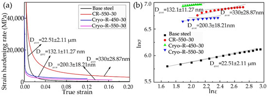
Figure 7.
(a) Work hardening curves and (b) Hollomon analysis of the specimens.
Figure 8 presents the sectional diagram of work hardening curves during uniform plastic deformation of three of the samples. Three different stages were identified: stage I is the work hardening rate at the preliminary stage of uniform plastic deformation; stage II is the work hardening rate at the end stage of uniform plastic deformation; and stage III is the transition between the stages I and II. The work hardening rate decreased sharply with the true strain at stage I, while it reduced tardily at stage II. The highest work hardening rate of 1.46 (GPa) at stage I was obtained in the specimen CR–550–30, while it decreased to 0.36 (GPa) and 0.26 (GPa) in the specimens Cryo–R–450–30 and Cryo–R–550–30. A very apparent transition stage, which accommodates more dislocation and alleviates stress concentration, was observed in specimen CR–550–30, while the transition stages gradually became blurred in the cryorolled specimens. The gradual inconspicuous transition stage (from Figure 8a to Figure 8b,c) indicated deteriorated work hardening.
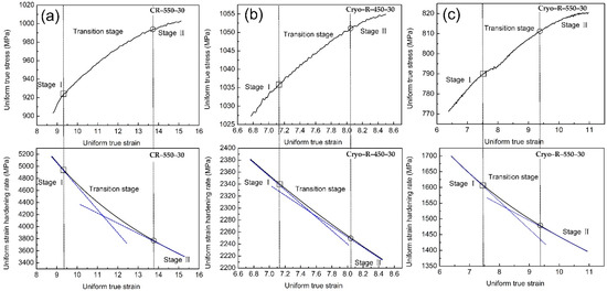
Figure 8.
Sectional diagram of work hardening curves during uniform plastic deformation in specimen (a) CR–550–30, (b) Cryo–R–450–30, and (c) Cryo–R–550–30.
It is commonly accepted that the tensile strength (TS) is the sum of yield strength (YS) and work hardening; therefore, the difference TS-YS intuitively reflected the work hardening ability. Figure 9 presents the relationship between the f/d and the TS-YS in all of the annealed specimens. Some information regarding microstructure and strength were referred to in our previous works [23,27,28,29]. It was evident that the work hardening ability (TS-YS) in low-carbon UFG steels with ferrite + cementite microstructures increased with the rise of f/d from specimen Cryo–R–550–30, to Cryo–R–450–30, and then to CR–550–30. This rule indicated that the relative larger volume fraction of fine θ particles resulted in better work hardening. Specimen Cryo–R–450–30 had the best tensile strength among all of the specimens (Figure 2), but the value of TS-YS was smaller than that of specimen CR–550–30; this indicated that the improvement of tensile strength in the specimen Cryo–R–450–30 was attributed to the higher yield strength, but not to the work hardening. The higher yield strength of specimen Cryo–R–450–30 mainly derived from the ultrafine α phase. The value of TS-YS in the specimen Cryo–R–550–30 was smaller than that of specimen Cryo–R–450–30, signifying the decrease in work hardening in specimen Cryo–R–550–30.
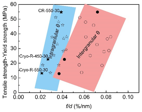
Figure 9.
Relationship between f/d and TS-YS in all specimens.
In addition, it is clear from the slope of the rectangle in Figure 9 that the f/dintra-θ played a more significant role in the improvement of work hardening (The star and circle represented the value of TS-YE of intragranular and intergranular θ particles). A slight increase of f/dintra-θ from specimen Cryo–R–550–30, to specimen Cryo–R–450–30, and then to specimen CR–550–30 (0.021→0.025→0.036 %/nm) led to the sharp increase in work hardening. Although there was very little change in the size of the intragranular θ particles, the f/dintra-θ was changed with the volume fraction of intragranular θ particles. The gradual decrease in the volume fraction of intragranular θ particles from specimen CR–550–30, to Cryo–R–450–30, and then to Cryo–R–550–30 was caused by the increased tendency of intergranular precipitation by cryorolling at LNT. This is because the cryorolling at LNT accumulates more distortion energy and subsequent crystal boundary energy, favoring the C diffusion towards to the grain boundaries and the intergranular precipitation.
The TEM morphology of the α + θ phase in the specimen Cryo–R–550–30, after yielding, is shown in Figure 10. It is noticeable that a large number of dislocations were accumulated around the intragranular and intergranular particles and the grain boundaries. These dislocations were reported to be geometrically necessary dislocations (GNDs) [34], and they normally formed at the grain boundaries and the phase interface between the θ particles and the α matrix. The GNDs that formed at the boundaries could ensure the continuity of the stress gradient during tensile deformation. Pressure or tensile stress was formed at the transverse and longitudinal direction of the θ particles, and then some GNDs were released at the phase interface to postpone the deformation of spherical θ particles. In addition, inter-phase stress brought about in the GNDs also contributed to the work hardening. It is apparent from Figure 10 that more GNDs were accumulated around the intragranular θ particles, and a relatively small amount of GNDs were observed around the intergranular θ particles. Some of the intragranular θ particles were covered by the tangled dislocation wall and were hardly observed. In addition, the increased grains after yielding were possibly caused by the tensile deformation. Furthermore, the blurred grain boundary, which had been reported, was observed in the tensile UFG specimen, also affecting the grain size observation [33].
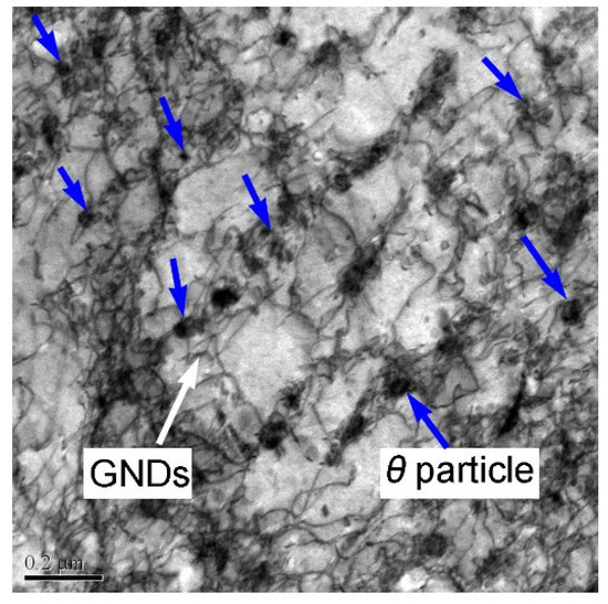
Figure 10.
TEM morphology of α + θ phase in the specimen Cryo–R–550–30 after yield.
The intragranular θ particles could prevent the dislocation movement and then store large amount of dislocation, helping to improve the yield strength and work hardening, while the intergranular θ particles with relatively large size took up the positions of the fractional grain boundaries, decreasing the accumulation capacity of dislocation at the grain boundaries and further impairing the strength of the grain boundaries. In addition, the dislocation loop formed at the dislocation intersection with the θ particles led to a strain gradient around the θ particles, which was beneficial to the work hardening. Therefore, the poorer work hardening of specimen Cryo–R–550–30 could be explained by the relatively greater amount of intergranular θ particles with large size. Moreover, the low tensile strength in specimen Cryo–R–550–30 was also related to the presence of relatively more intergranular θ particles, which reduced the strength of the grain boundaries and the yield strength.
4. Conclusions
In the present study, rolling/cryorolling and annealing processes are adopted to fabricate the low-carbon UFG steel with ferrite + cementite microstructures. The following conclusions are drawn:
- (1)
- Optimal balance between the strength and work hardening in the low-carbon UFG steels is realized by the α and θ phases. It was important to adjust the rolling and annealing processes from the viewpoint of industrial production in order to fabricate the UFG steels with a relative coarsening α phase and dispersedly distributed intragranular θ particles, which guarantees the better work hardening of UFG steels.
- (2)
- The cryorolling process substantially improved the tensile strength of low-carbon UFG steel, but concurrently deteriorated the work hardening behavior. The work hardening ability increased with the rise of the volume fraction and the decreased size of cementite particles. The highest work hardening rate, at the stage I of 1.46 (GPa), was obtained in the specimen CR–550–30 (cold-rolled and annealed at 550 °C for 30 min), while it decreased to 0.36 (GPa) and 0.26 (GPa) in the specimens Cryo–R–450–30 (cryorolled and annealed at 450 °C for 30 min) and Cryo–R–550–30 (cryorolled and annealed at 550 °C for 30 min).
- (3)
- The α grain size was decreased to 132 ± 11 nm and 200 ± 19 nm in specimens Cryo–R–450–30 and Cryo–R–550–30, which were smaller than that obtained in specimen CR–550–30. The specimen Cryo–R–550–30 had a tensile strength of 740.3 MPa, which was lower than that in the specimens Cryo–R–450–30 (970.2 MPa) and CR–550–30 (867.3 MPa).
- (4)
- The intergranular θ particles, without well dislocation accumulation ability, impair the strength of grain boundaries and the work hardening of α + θ ultrafine grain steels.
Author Contributions
Conceptualization, Z.W., Q.Y. and G.X.; methodology, Q.Y. and G.X.; software, Z.W.; validation, Q.Y., Q.Z. and G.X.; formal analysis, Z.W., Q.Y., Q.Z. and G.X.; investigation, Z.W., Q.Y. and Z.Z.; resources, G.X., Q.Y. and Z.Z.; data curation, Z.W. and Q.Y.; writing—original draft preparation, Z.W. and Q.Y.; writing—review and editing, Z.W., Q.Y. and G.X.; visualization, Q.Y., Q.Z. and G.X.; supervision, Q.Y. and G.X.; project administration, Q.Y. and Z.Z.; funding acquisition, Q.Y. and G.X. All authors have read and agreed to the published version of the manuscript.
Funding
This research was funded by the National Natural Science Foundation of China (NSFC) (Nos. 52004193 and 51874216), and the China Postdoctoral Science Foundation (No. 2022M710596).
Institutional Review Board Statement
Not applicable.
Informed Consent Statement
Not applicable.
Data Availability Statement
Not applicable.
Conflicts of Interest
The authors declare no conflict of interest. The funders had no role in the design of the study; in the collection, analyses, or interpretation of data; in the writing of the manuscript; or in the decision to publish the results.
References
- Zhang, R.W.; Cao, Q.; Peng, Z.J.; Shi, J.; Dong, H.; Huang, C.X. Intercritical rolling induced ultrafine microstructure and excellent mechanical properties of the medium-Mn steel. Mater. Sci. Eng. A 2013, 58, 84–88. [Google Scholar] [CrossRef]
- Lu, K. Making strong nanomaterials ductile with gradients. Science 2014, 345, 1455–1456. [Google Scholar] [CrossRef]
- Tsuji, N.; Ueji, R.; Minamino, Y.; Saito, Y. A new and simple process to obtain nano-structured bulk low-carbon steel with superior mechanical property. Scr. Mater. 2002, 46, 305–310. [Google Scholar]
- Ueji, R.; Tsuji, N.; Minamino, Y.; Koizumi, Y. Ultragrain refinement of plain low carbon steel by cold rolling and annealing of martensite. Acta Mater. 2002, 50, 4177–4189. [Google Scholar] [CrossRef]
- Liang, J.W.; Shen, Y.F.; Misra, R.D.K.; Liaw, P.K. High strength-superplasticity combination of ultrafine-grained ferritic steel: The significant role of nanoscale carbides. J. Mater. Sci. Technol. 2021, 83, 131–144. [Google Scholar]
- Kalashami, A.G.; Kermanpur, A.; Ghassemali, E.; Najafizadeh, A.; Mazaheri, Y. Correlation of microstructure and strain hardening behavior in the ultrafine-grained Nb-bearing dual phase steels. Mater. Sci. Eng. A 2016, 678, 215–226. [Google Scholar]
- Hamzeh, M.; Kermanpur, A.; Najafizadeh, A. Fabrication of the ultrafine-grained ferrite with good resistance to grain growth and evaluation of its tensile properties. Mater. Sci. Eng. A 2014, 593, 24–30. [Google Scholar] [CrossRef]
- Wang, H.T.; Tao, N.R.; Lu, K. Strengthening an austenitic Fe-Mn steel using nanotwinned austenitic grains. Acta Mater. 2012, 60, 4027–4040. [Google Scholar]
- Calcagnotto, M.; Ponge, D.; Demir, E.; Raabe, D. Orientation gradients and geometrically necessary dislocations in ultrafine grained dual-phase steels studied by 2D and 3D EBSD. Mater. Sci. Eng. A 2010, 527, 2738–2746. [Google Scholar] [CrossRef]
- Song, R.; Ponge, D.; Raabe, D.; Speer, J.G.; Matlock, D.K. Overview of processing, microstructure and mechanical properties of ultrafine grained bcc steels. Mater. Sci. Eng. A 2006, 441, 1–17. [Google Scholar] [CrossRef]
- Zhao, L.J.; Park, N.; Tian, Y.Z.; Chen, S.; Shibata, A.; Tsuji, N. Novel thermomechanical processing methods for achieving ultragrain refinement of low-carbon steel without heavy plastic deformation. Mater. Res. Lett. 2016, 5, 61–68. [Google Scholar] [CrossRef]
- Ma, Y.Q.; Jin, J.E.; Lee, Y.K. A repetitive thermomechanical process to produce nano-crystalline in a metastable austenitic steel. Scr. Mater. 2005, 52, 1311–1315. [Google Scholar] [CrossRef]
- Gazder, A.A.; Hazra, S.S.; Perefoim, E.V. Annealing behaviour and mechanical properties of severely deformed interstitial free steel. Mater. Sci. Eng. A 2011, 530, 492–503. [Google Scholar] [CrossRef]
- Yu, C.Y.; Kao, P.W.; Chang, C.P. Transition of tensile deformation behaviours in ultrafine-grained aluminium. Acta Mater. 2005, 53, 4019–4028. [Google Scholar] [CrossRef]
- Ma, E. Instabilities and ductility of nanocrystalline and ultrafine-grained metals. Scr. Mater. 2003, 49, 663–668. [Google Scholar] [CrossRef]
- Rao, P.N.; Singh, D.; Jayaganthan, R. Mechanical properties and microstructural evolution of Al 6061 alloy processed by multidirectional forging at liquid nitrogen temperature. Mater. Des. 2014, 56, 97–104. [Google Scholar] [CrossRef]
- Wang, Y.M.; Chen, M.W.; Zhou, F.H.; Ma, E. High tensile ductility in a nanostructured metal. Nature 2002, 419, 912–915. [Google Scholar] [CrossRef]
- Zhao, Y.Y.; Wang, J.F.; Zhou, S.; Wang, X.D. Effects of rare earth addition on microstructure and mechanical properties of a Fe-15Mn-1.5A1-0.6C TWIP steel. Mater. Sci. Eng. A 2014, 608, 106–113. [Google Scholar]
- Song, R.; Ponge, D.; Raabe, D. Mechanical properties of an ultrafine grained C-Mn steel processed by warm deformation and annealing. Acta Mater. 2005, 53, 4881–4892. [Google Scholar] [CrossRef]
- Li, X.; Jing, T.F.; Lu, M.M.; Zhang, J.W. Microstructure and mechanical properties of ultrafine lath-shaped low carbon steel. J. Mater. Eng. Perform. 2012, 21, 1496–1499. [Google Scholar] [CrossRef]
- Hosseini, S.M.; Alishahi, M.; Najafizadeh, A.; Kermanpur, A. The improvement of ductility in nano/ultrafine grained low carbon steels via high temperature short time annealing. Mater. Lett. 2012, 74, 206–208. [Google Scholar]
- Tsuji, N.; Maki, T. Enhanced structural refinement by combining phase transformation and plastic deformation in steels. Scr. Mater. 2009, 60, 1044–1049. [Google Scholar] [CrossRef]
- Yuan, Q.; Xu, G.; Liu, M.; Hu, H.J.; Tian, J.Y. Effects of rolling temperature on the microstructure and mechanical properties in an ultrafine-grained low-carbon steel. Steel Res. Int. 2018, 2, 1800318. [Google Scholar] [CrossRef]
- Park, K.T.; Kim, Y.S.; Lee, J.G.; Shin, D.H. Thermal stability and mechanical properties of ultrafine grained low carbon steel. Mater. Sci. Eng. A 2000, 293, 165–172. [Google Scholar] [CrossRef]
- Furuhara, T.; Mizoguchi, T.; Maki, T. Ultra-fine (α+θ) Duplex Structure Formed by Cold Rolling and Annealing of Pearlite. ISIJ Int. 2005, 45, 392–398. [Google Scholar] [CrossRef]
- Syn, C.K.; Lesuer, D.R.; Sherby, O.D. Influence of microstructure on tensile properties of spheroidized ultrahigh-carbon (1.8 Pct C) steel. Met. Mater. Trans. A 1994, 25, 1481–1493. [Google Scholar] [CrossRef]
- Yuan, Q.; Xu, G.; Liu, S.; Liu, M.; Hu, H.J. Effect of strain rate on the microstructure of warm-deformed ultrafined medium-carbon steel. Arch. Met. Mater. 2018, 4, 1805–1813. [Google Scholar]
- Yuan, Q.; Xu, G.; Liu, S.; Liu, M.; Hu, H.J.; Li, G.Q. Effect of rolling reduction on microstructure and property of ultrafine grained low-carbon steel processed by cryorolling martensite. Metals 2018, 8, 518. [Google Scholar] [CrossRef]
- Yuan, Q.; Xu, G.; Liu, M.; Liu, S.; Hu, H.J. Evaluation of mechanical properties and microstructures of ultrafine grain low-carbon steel processed by cryorolling and annealing. Trans. Indian Inst. Met. 2019, 72, 741–749. [Google Scholar]
- Avishan, B.; Garcia-Mateo, C.; Morales-Rivas, L.; Yazdani, S.; Caballero, F.G. Strengthening and mechanical stability mechanisms in nanostructured bainite. J. Mater. Sci. 2013, 48, 6121–6132. [Google Scholar] [CrossRef]
- Belde, M.; Springer, H.; Raabe, D. Vessel microstructure design: A new approach for site-specific core shell micromechanical tailoring of TRIP-assisted ultra-high strength steels. Acta Mater. 2016, 113, 19–31. [Google Scholar] [CrossRef]
- Gan, X.L.; Yuan, Q.; Zhao, G.; Ma, H.W.; Liang, W.; Xue, Z.L.; Qiao, W.W.; Xu, G. Quantitative analysis of microstructures and strength of Nb-Ti microalloyed steel with different Ti additions. Met. Mater. Trans. A 2020, 5, 2084–2096. [Google Scholar] [CrossRef]
- Zheng, C.S.; Li, L.F. Effect of microstructure on mechanical behavior for eutectoid steel with ultrafine- or fine-grained ferrite+cementite structure. Mater. Sci. Eng. A 2017, 688, 83–91. [Google Scholar] [CrossRef]
- Zheng, C.S.; Li, L.F.; Wang, Y.D.; Yang, W.Y.; Sun, Z.Q. Micromechanical behaviour of eutectoid steel quantified by ananalytical model calibrated by in situ synchrotron-based X-ray diffraction. Mater. Sci. Eng. A 2015, 631, 181–188. [Google Scholar] [CrossRef]


Publisher’s Note: MDPI stays neutral with regard to jurisdictional claims in published maps and institutional affiliations. |
© 2022 by the authors. Licensee MDPI, Basel, Switzerland. This article is an open access article distributed under the terms and conditions of the Creative Commons Attribution (CC BY) license (https://creativecommons.org/licenses/by/4.0/).