Abstract
In this paper, molecular dynamics (MD) simulations are used to investigate the effects of machining parameters on the nanomachining and subsurface defect evolution of single crystal γ-TiAl alloys with water medium. The changes of cutting force and cutting temperature with water medium were analyzed in the nano-cutting process, and the subsurface defects and crystal structure changes of the workpiece were studied by common neighbor analysis (CNA) method. The results show that increasing the cutting speed appropriately can reduce the friction between the workpiece and the tool, and improve the machining efficiency. With the increase in cutting depth, the temperature of the Newtonian layer increases gradually, and the cooling of the water medium reduces the temperature of the workpiece. The defect evolution becomes severe and the number of BCC atoms increases with the increase in cutting depth. With the increase in cutting distance, the number of HCP atoms decreases and the number of BCC atoms basically remains stable. In addition, as the cutting speed increases, the internal stress of the workpiece gradually extends to the inside of the workpiece along the depth direction. There is more compressive stress in the unmachined area and the shear zone between the tool and the workpiece.
1. Introduction
With the rapid development of nano-cutting, the concept of ultra-precision machining has gradually turned to green machining, and high-efficiency and high-precision machining methods have occupied the core position in precision molding technology at home and abroad [1]. However, with a new type of high-temperature structural material, γ-TiAl alloy, it is easy to introduce defects and residual stress [2,3] during processing due to its shortcomings such as difficult deformation processability and room temperature brittleness [4,5], which seriously affect the mechanical properties and service performance of the workpiece [6,7]. In order to reduce the microcracks [8] and residual stress generated in the cutting process [9], it is effective to plastically process brittle materials such as γ-TiAl alloy at the nanometer scale. Looking at the research results of nano-cutting for difficult-to-machine alloys, it is found that most of them describe the causes of defects, residual stress distribution and machinability through different processing methods or different research angles [10,11,12].
At present, the cutting process simulation of metal materials under different cutting processes has been widely studied [13,14], and research on the nano-cutting process has also received extensive attention [15]. However, the basic nano-cutting process for γ-TiAl alloy has not been fully explained, and there are few reports on the research of machining parameters for nanomachining. In fact, in any manufacturing process, the presence of cutting fluid between the tool and the workpiece material brings mutual friction to the machining system [16]. In the machining process, the direct benefits of rational use of cutting fluid can lubricate the tool [17], reduce friction with the workpiece to prolong tool life [18], decrease the cutting force and improve the processing quality [19]. In the context of green manufacturing, rational use of cutting fluids in sustainable manufacturing can reduce energy consumption [20], improve product quality, achieve better health and safety conditions, and improve the overall performance of mechanical systems [21]. To this end, for brittle alloys such as γ-TiAl alloys, it is necessary to study nano-cutting with different machining parameters containing cutting fluids. It is of great significance to reveal the influence of process parameters at the nanoscale on the evolution of defects and the mechanism of residual stress in nanomachining [22].
In order to deeply understand the influence of water medium on the nano-cutting of single crystal γ-TiAl alloy, the influence of water medium as cutting fluid on the mechanical properties of materials was studied. How to choose the appropriate cutting speed, depth of cut, cooling conditions and tool materials to influence the material properties is one of the key contents of the current research. Therefore, this paper improves the nano-cutting process for single crystal γ-TiAl alloy in a vacuum environment, and replaces the cutting fluid with water to simulate the nano-cutting close to reality. Through the comparative analysis of the simulation results of the nano-cutting model for single crystal γ-TiAl alloy in an aqueous medium under different processing parameters, the difference under different cutting processes is clarified.
The results of this study explain the influence of the participation of water medium on the machining process, which can lay a foundation for understanding the machining process of brittle materials such as single crystal γ-TiAl alloy and provide a theoretical supplement for nanocutting brittle materials. At the same time, this study can provide a theoretical reference for the rational formulation of parts processing technology, and theoretical guidance for the development of ultra-precision machining and the promotion of green manufacturing is provided.
2. Methods
2.1. Simulation Model
Figure 1 shows the established MD models of single-crystal γ-TiAl alloy. The model size is 200.05 × 146.335 × 120.03 Å, with a total of 204,570 atoms, which are divided into boundary layer, constant temperature layer and Newtonian layer. The boundary layer plays the role of fixing the workpiece. The atoms in the constant temperature layer use the Nosé–Hoover thermal bath method to control the temperature of the workpiece to be 300 K, which is conducive to heat absorption and heat dissipation between atoms [23]. The atoms in the constant temperature layer and the Newton layer follow Newton’s second law [24].
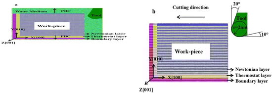
Figure 1.
MD simulation model of single crystal γ-TiAl alloy ((a), with water medium (b), without water medium).
Because the hardness of γ-TiAl alloy is much smaller than that of diamond [25], diamond is selected as the tool material and set as a rigid body, containing 10,301 C atoms. The TIP4P-2005 water medium model is selected [26], and during the simulation process, 43,368 water molecules are randomly distributed in the entire free space around the workpiece. The temperature of the water molecules and the constant temperature layer of the workpiece is kept at 300 K to achieve heat dissipation. In addition, the cutting process is carried out after sufficient relaxation under NVE [27]. In order to reduce the influence of the size effect, the fixed boundary condition (FBC) is adopted in (100) direction, and period boundary conditions (PBC) in the (010) and (001) directions are adopted.
In the nano-machining simulation, in order to better approximate real machining, in combination with the characteristics of γ-TiAl alloy and the parameters selected by existing researchers, the cutting depth is set to 2 nm, 3 nm and 4 nm. Furthermore, the selected two cutting speeds of 100 m/s and 200 m/s were compared and analyzed to study the influence of machining parameters on nano-cutting [28]. The specific simulation parameters are shown in Table 1, and the parameters of the material are shown in Table 2.

Table 1.
Cutting parameters.
Table 2.
Material model parameters.
2.2. Potential Function
The selection of the potential function in the MD cutting simulation plays a decisive role in the simulation results [29]. The system model is divided into three parts: workpiece, tool and water medium, and it contains five atom types, namely Ti, Al, C, H and O atoms. The interposition potential energy between Ti-Al atoms in the workpiece and the atomic intercalation energy in the system are described by the embedded atom method (EAM) [30]. The formula is as follows:
where Fi represents the atom embedding energy, ρi represents the sum of electron cloud densities generated at i except i atom; represents the mutual potential energy between atoms; ϕij represents the pair potential function between the i and j atoms, and rij is the distance between the i and j atoms.
The many-body potential between Ti atoms and Al atoms in the workpiece and C atoms in the tool is described by Morse potential [31]. The formula of morse potential energy between Ti-C and Al-C is as follows:
where E (E Ti-C, E Al-C) represents cohesive energy; α (α Ti-C, α Al-C) represents the elastic coefficient; r0 (rTi-C, rAl-C) represents the equilibrium distance between Ti-C and Al-C atoms; and rij is the distance between atoms i and j. In the process of analysis, the tool is treated as rigid and does not consider the interaction between diamond atoms. The specific parameter values are shown in Table 3.
Table 3.
Parameter values in Morse potential.
The Lennard–Jones (L–J) [32] potential is used to calculate the interaction of water molecules with other atoms; the L–J potential represents a weak hydrogen bond-like interaction in water medium without chemical reactions [33]. The formula is as follows:
where σ represents the regulation parameter when the interaction potential energy is equal to 0, ε is the depth of the potential well, and r is the atomic spacing. The meanings of the sixth power and the twelfth power represent the mutual attraction and repulsion energies between atoms, respectively. The L–J potential parameters between different atoms are shown in Table 4.
Table 4.
Inter-atomic L-J potential parameters.
3. Results and Discussion
3.1. Cutting Force and Cutting Temperature at Different Cutting Depths
In order to compare the change in cutting force when cutting with water medium and without water medium, when the cutting speed is 100 m/s, the cutting force with cutting depth of 2 nm, 3 nm and 4 nm in the two cases is analyzed. Figure 2 shows the variation of cutting force when cutting with different depths without water medium. The black, red and blue are respectively tangential force (Fx), normal force (Fy) and axial force (Fz); Fx, Fy and Fz are along X, Y and Z axis negative direction.
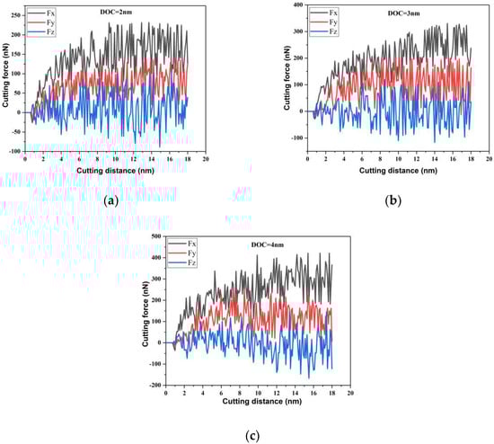
Figure 2.
Cutting force at different cutting depths with water medium ((a) cutting depth is 2 nm (b) cutting depth is 3 nm (c) cutting depth is 4 nm).
It can be seen from Figure 2 that when the cutting speed is constant, with the increase in the cutting depth, the chips accumulated at the front end of the tool increase and the cutting force gradually increases as the resistance of the tool increases. When the cutting depth is 4 nm, the cutting force fluctuates greatly. It shows that the increase in cutting depth causes more atomic bonds of γ-TiAl alloy in the workpiece to be broken, and relatively more chips in the workpiece accumulate at the front end of the tool, which requires more cutting force to remove the chips. From the value and fluctuation of the axial force Fz in Figure 2, it can also be found that due to the periodic boundary conditions, the average axial force in the Z direction is about 0 nN. In addition, the tangential force increases as the depth of Fx and Fy gradually increase, and Fx is much larger than Fy, which indicates that the tangential force Fx dominates the cutting process, and the chips are mainly removed in the form of shearing instead of being squeezed. The effect of Fx is more obvious when the cutting depth is 4 nm.
When cutting with water medium, the change in cutting force is similar to that in cutting without water medium. As shown in Figure 3, with the increase in cutting depth, the cutting force gradually increases; the value of Fx when cutting with water medium is smaller than that when cutting without water medium, and the degree of reduction of the normal force Fy also reduced. However, on the whole, the fluctuation of cutting force during cutting with water medium is reduced, and the presence of water medium reduces the plastic deformation of the material. Compared with macroscopic machining, the amount of material removed at the nanoscale is relatively small. The participation of water medium makes plastic deformation of the material difficult, and the cooling and lubricating effect of water medium reduces the cutting force required for machining to a certain extent.
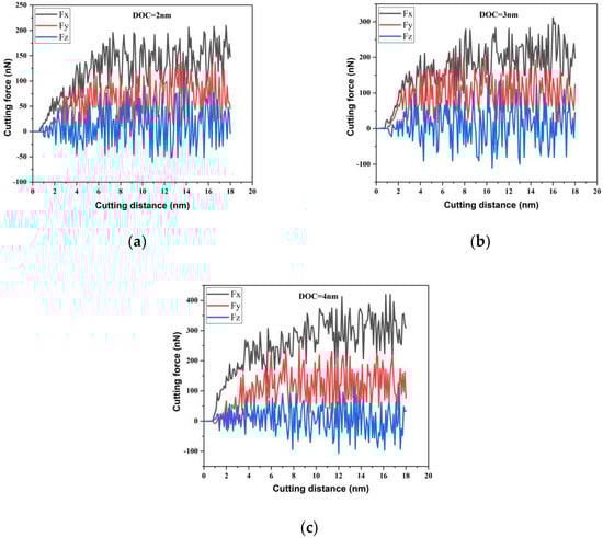
Figure 3.
Cutting force at different cutting depths with water medium ((a) cutting depth is 2 nm (b) cutting depth is 3 nm (c) cutting depth is 4 nm).
The average cutting force and average friction coefficient at different depths are shown in Figure 4. It can be seen from Figure 4a that the average cutting force Fx increases from 166.88 nN to 301.099 nN, and the average normal force Fy increases from 81.989 nN and grows to 140.805 nN. The average cutting force Fx increases from 143.919 nN to 261.965 nN and the average normal force Fy increases from 57.1193 nN to 94.1772 nN during cutting with water medium. The growth rate of the average cutting force Fx is much greater than that of the average normal force Fy, indicating that the deeper the cutting depth, the greater the cutting force required in the cutting direction.
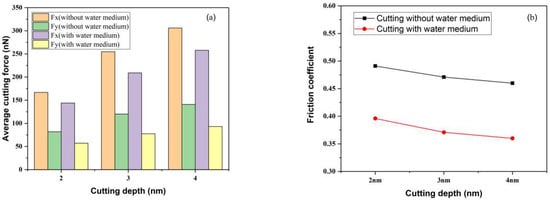
Figure 4.
Cutting force and friction coefficient at different cutting depths ((a) cutting force at different cutting depths (b) friction coefficient at different cutting depths).
The average cutting force and average friction coefficient at different depths are shown in Figure 4a, which shows that the average cutting force Fx increases from 166.88 nN to 301.099 nN, and the average normal force Fy increases from 81.989 nN to 140.805 nN when cutting in water-free medium. When cutting in water medium, the average cutting force Fx increased from 143.919 nN to 261.965 nN, and the average normal force Fy increased from 57.1193 nN to 94.1772 nN. The growth rate of the average cutting force Fx was much higher than the average normal force Fy, indicating that the deeper the cutting depth, the greater the cutting force required in the cutting direction. The average coefficient of friction at different depths of cut was calculated as the ratio of the average normal force Fy to the average tangential force Fx. It can be seen from Figure 4b that the average friction coefficient decreases with the increase in the cutting depth. On the one hand, the increase in the cutting depth increases the chip atoms at the front end of the tool, which increases the hindering effect of the tool. On the other hand, the decrease in the average friction coefficient indicates that the average cutting force Fx is dominant. In addition, the average friction coefficient of cutting with water medium is smaller than that of cutting without water medium, indicating that the lubrication effect of water medium reduces the friction between the tool and the workpiece, and reduces the friction resistance of the tool.
Different cutting depths have different effects on the average temperature of the workpiece in different environments. The presence of the water medium reduces the heat transfer between the workpiece and the chips, reducing the temperature of the workpiece. Figure 5 shows the temperature distribution curves of the Newtonian layer of the workpiece at different cutting depths under different cutting environments. As the cutting depth increases, the shear deformation of the chip and the work done by the friction between the tool and the workpiece are converted into cutting heat, and the increasing cutting heat gradually increases the cutting temperature.
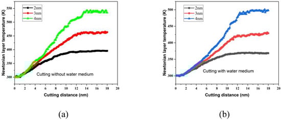
Figure 5.
Newtonian layer temperature of workpiece under different cutting environments ((a) without water medium (b) with water medium).
When the cutting depth is large, the contact area between the tool and the workpiece increases, and the extrusion degree between the tool and the workpiece atoms increases. Moreover, the lattice energy released by the lattice deformation in the γ-TiAl alloy is converted into heat energy, resulting in the temperature of the Newtonian layer increasing with the increasing depth of cut. In addition, with the increase in cutting depth, some atoms behind the tool undergo lattice reconstruction and elastic recovery of the subsurface, so that the cutting temperature gradually increases and then tends to a stable state. In the process of cutting with water medium, due to the cooling of the water medium and the thermal balance of the constant temperature layer, the overall energy conversion of the workpiece is accelerated. Therefore, the temperature of the Newtonian layer during cutting with water medium is relatively small.
Figure 6 shows the temperature distribution of the workpiece during cutting with or without water medium. Figure 6a,c,e show the temperature distribution inside the workpiece when the cutting depth is 2 nm, 3 nm and 4 nm, respectively, when cutting without water medium. Figure 6b,d,f show the temperature distribution inside the workpiece when the cutting depth is 2 nm, 3 nm and 4 nm, respectively, when cutting with water medium.
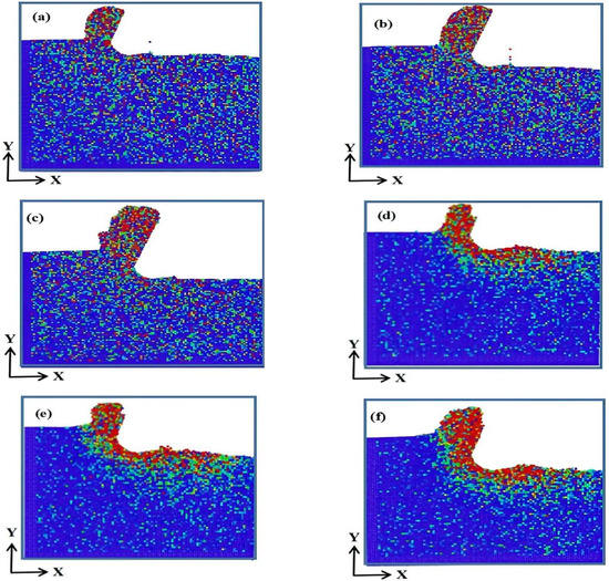
Figure 6.
Internal temperature of workpiece under different cutting environments ((a) cutting depth is 2 nm and without water medium (b) cutting depth is 3 nm and without water medium (c) cutting depth is 4 nm and without water medium (d) cutting depth is 2 nm and with water medium (e) cutting depth is 3 nm and with water medium (f) cutting depth is 4 nm and with water medium).
It can be seen from Figure 6 that during the cutting process without water medium, the highest temperature zone inside the workpiece is at the top of the chip, which is distributed inside the workpiece from top to bottom. However, the highest temperature zone in the cutting process with water medium is in the contact area between the chip, the tool and the workpiece. When entering the cutting, it is far from the constant temperature layer, and the heat generated by the extrusion and shearing action of the tool diffuses from the front end of the tool to the chips and the inside of the workpiece. Due to the effect of the constant temperature layer and the participation of the water medium, where the workpiece is surrounded by the water medium, part of the generated heat of the workpiece is taken away by the water medium, while the other part is diffused along the rake facing the chip and the machined surface. Therefore, when the water medium is used with the cutting, no more heat remains inside the workpiece, and the temperature in the workpiece is relatively low.
3.2. Influence of Cutting Depth on Defect Evolution
Different depths of cut lead to different evolution of defects inside the workpiece, especially in cutting with aqueous media. Figure 7 and Figure 8 show the distribution of defect atoms for different defects inside workpieces cut without water medium and with water medium. CNA technology was used to identify the defective atoms, and the normal FCC structure atoms in the figure were deleted.
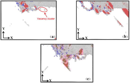
Figure 7.
Distribution of subsurface defects at different cutting depths (without water medium) ((a) cutting depth is 2 nm (b) cutting depth is 3 nm (c) cutting depth is 4 nm).
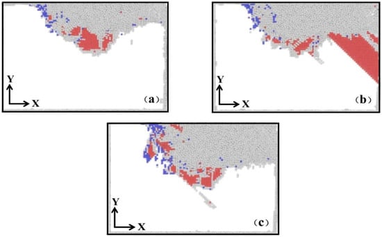
Figure 8.
Distribution of subsurface defects at different cutting depths (with water medium) ((a) cutting depth is 2 nm (b) cutting depth is 3 nm (c) cutting depth is 4 nm).
The red is HCP atoms, the blue is BCC atoms, and the cutting depths of a, b and c are 2 nm, 3 nm and 4 nm, respectively. In the process of subsurface defect evolution, the defects in the processed region are mainly composed of intrinsic stacking faults and vacancy clusters. When the cutting depth is 2 nm, the defects under the tool begin to increase, and a small number of vacancy clusters are generated on the subsurface and stacking faults are generated inside the workpiece, as shown in Figure 7a.
With the increase in cutting depth, the number of vacancy clusters increases. This is because vacancy is a thermal defect, and the vacancy concentration is proportional to the temperature [34]. When the cutting depth gradually increases, the temperature generated by the workpiece cutting increases, so the vacancy concentration increases. In addition, as the cutting progresses, dislocations are emitted at the front end of the tool in the advancing direction, and the dislocations directly below the tool gradually nucleate and migrate into the workpiece, as shown in Figure 7b. When the cutting depth is 4 nm, the internal defects of the workpiece increase, and there are many stacking fault defects left in the workpiece after cutting, such as atomic groups and intrinsic stacking faults, as shown in Figure 7c. This is because as the cutting depth increases, the cutting force and cutting temperature are relatively large, which provides conditions for the nucleation and expansion of defects. From the perspective of the evolution of dislocations at different cutting depths, during the cutting process the stacking faults are constantly evolving in the machining area in front of the tool and directly below the tool. With the generation of incomplete dislocations during the evolution process, the evolution of defects in the machined area becomes severe with the increasing depth of cut.
It can be seen from Figure 8 that the evolution of dislocations in the cutting process with water medium is similar to that in cutting without water medium. As the cutting distance increases, dislocations are generated in front of the tool, and a small amount of vacancies and atomic groups appear on the machined surface. The dislocations in the process are dominated by intrinsic stacking faults. Due to the cooling effect of the water medium, the temperature of the workpiece is lowered, and the vacancy concentration is low. With the increase in cutting depth, due to the existence of water medium, the plastic deformation of γ-TiAl material is reduced, the number of intrinsic stacking faults in the machined area below the tool increases, and more BCC atoms are generated at the front end of the tool.
The presence of the water medium means that part of the heat generated in the cutting process is taken away by the water medium, and the temperature of the workpiece is relatively small. With the increase in the cutting depth, the BCC atoms increase, but the relative decrease in the temperature makes the dislocations happen not at the front end of the tool for machining, and the regions form dislocation emission, as shown in Figure 8b. When the cutting depth increased to 4 nm, the BCC atoms inside the workpiece increased more obviously, as shown in Figure 8c. In addition, during the cutting process in aqueous medium, the plastic deformation of the material is reduced, so that more amorphous atoms appear on the machined surface.
Figure 9 is the crystal structure transformation curve under different cutting depths. Figure 9a,b are the HCP crystal structure transformation curves, and Figure 9c,d are the BCC crystal structure transformation curves; in the figure, black, red and green are the cutting depths of 2 nm, 3 nm and 4 nm, respectively. Different cutting depths have different crystal structure transitions.
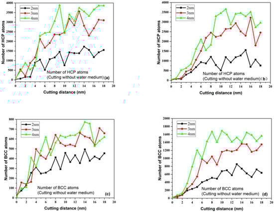
Figure 9.
Crystal structure transition curves at different cutting depths. ((a). number of HCP atoms at different cutting depths without water medium (b). number of HCP atoms at different cutting depths with water medium (c). number of BCC atoms at different cutting depths without water medium (d). number of BCC atoms at different cutting depths with water medium).
When cutting without water medium, the number of HCP atoms increases with the increase in the depth of cut. This is because when the depth of cut is large, the slip system in the workpiece is activated, and the temperature of the workpiece increases with the increase in the depth of cut. The defect atoms obtain enough energy to generate slip; not only is there the transformation of single atoms, but also the nucleation and expansion of intrinsic stacking faults and the increase in crystal structure transformation. Therefore, the number of defect atoms increases rapidly. The number of HCP atoms also increases when the cutting depth is 4 nm.
Compared with cutting without water medium, the cooling of the water medium during cutting with water medium makes the increase rate of HCP atoms relatively small. When the cutting distance is 8 nm, the number of defect atoms in the workpiece fluctuates greatly, due to the friction between the workpiece and the tool. Due to the increased friction between the workpiece and the tool, even though the presence of the water medium reduces the workpiece temperature, it has little effect on the workpiece temperature in the stable cutting stage. When cutting to the middle of the workpiece, the temperature of the workpiece is relatively stable, and there is enough heat to activate the slip system of the defect. Therefore, the HCP atoms at this time fluctuate greatly and the number is not much different from that found when cutting with water medium.
From Figure 7 and Figure 9c,d, it can be seen that the BCC atoms inside the workpiece gradually increase with the increase in cutting depth. There is not enough cutting force and cutting temperature to activate more slip systems when the cutting distance is small. In addition to the HCP crystal structure transformation, the workpiece begins to transform with a small part of the BCC crystal structure, and the BCC atoms increase with the depth of cut. It is obvious from Figure 9c,d that the number of BCC atoms when cutting with water medium is much larger than that without water medium. This phenomenon may be related to the cooling of the water medium in the cutting process. The main nucleated HCP atoms in the cutting process are due to the decrease in workpiece temperature that leads to more BCC atoms, and there is a competitive relationship between HCP and BCC atoms in the stable stage during the cutting process. When the number of HCP atoms increases, the number of BCC atoms decreases relatively.
When the cutting depth is 4 nm, the crystal structure evolution is the most intense, and there are more curve fluctuations caused by the nucleation and expansion of intrinsic stacking faults. In addition, as the cutting distance increases, the atoms behind the tool undergo elastic recovery and lattice reconstruction, and the increase of the number of HCP atoms and BCC atoms tends to slow down. In the nano-cutting of γ-TiAl alloy, only a very small part of the FCC atoms are converted into HCP and BCC atoms, and most of the FCC atoms are identified as amorphous atoms. With the increase in cutting distance, amorphous atoms can not only amorphize to form an amorphous phase, but can also transform into a new crystal structure through crystallization. Therefore, the fluctuation of BCC atoms during cutting is smaller than that of HCP atoms and is relatively stable at the later stage of cutting.
3.3. Influence of Cutting Depth on Internal Stress
The magnitude of the hydrostatic stress inside the workpiece can measure the stress state of the local processing area of the workpiece. The stress distribution of the workpiece processing area can be judged by combining the tensile and compressive stress state of the atoms. Different dislocations can be induced by hydrostatic stress, resulting in material deformation; the magnitude of hydrostatic stress is related to the degree of stacking fault and crystal structure damage inside the workpiece [35].
Figure 10 has coloring according to the hydrostatic stress value when the depth of cut is 2 nm, 3 nm and 4 nm. Figure 10a–c show the hydrostatic stress distribution at different cutting depths without water medium and Figure 10d–f show it with water medium cutting. Due to the difficult deformation processability of γ-TiAl alloy, it is necessary to apply a large external force to make the substrate deform elastically during cutting, and stress concentration will occur at the front end of the tool during cutting. This is due to the violent interaction between the tool and the workpiece during the machining process. During the movement of the tool, the machined surface is deformed and tensile stress is generated on the cutting surface. When the tool leaves, the machined surface is under the action of the internal atoms to generate compressive stress.
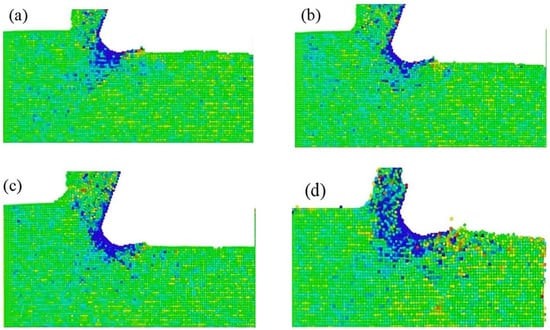
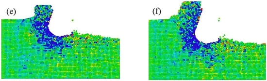
Figure 10.
Internal stress distribution at different cutting depths ((a) cutting depth is 2 nm and without water medium (b) cutting depth is 3 nm and without water medium (c) cutting depth is 4 nm and without water medium (d) cutting depth is 2 nm and with water medium (e) cutting depth is 3 nm and with water medium (f) cutting depth is 4 nm and with water medium).
When cutting without water medium, as the depth of cut increases, it can be seen that the compressive stress of the machined surface is smaller than the area where the elastoplastic deformation of the front end of the tool is occurring. This is because the extrusion of the tool and the workpiece during the cutting process causes some atoms in the processing area to be pressed into the material matrix, and the elastic recovery of the workpiece and the joint action of the tool flank make some of the atoms pressed into the matrix move to the subsurface. Under the action of the matrix, compressive stress is generated. When cutting with water medium, due to the violent movement of water molecules, the shear deformation area at the front end of the prop will form more compressive stress due to the extrusion of the tool and the workpiece with the water molecules.
3.4. Changes of Cutting Force and Newtonian Layer Temperature at Different Cutting Speeds
Figure 11 shows the change in cutting force at different cutting speeds when the cutting depth is 3 nm. It can be seen from the figure that the cutting speed has a great influence on the cutting force. Figure 11a,d correspond to cutting speeds of 100/s and 200 m/s, respectively.
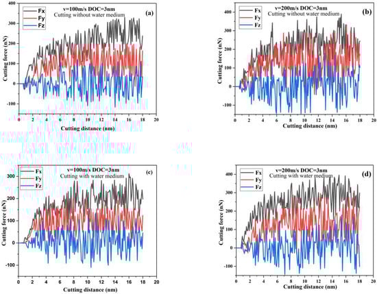
Figure 11.
Cutting force at different cutting speeds ((a) cutting speed is 100 m/s and without water medium (b) cutting depth is speed is 200 m/s and without water medium (c) cutting speed is 100 m/s and without water medium (d) cutting speed is 200 m/s and with water medium).
It can be seen from Figure 11 that with the increase in cutting speed, the cutting force gradually increases. When the cutting speed is 100 m/s, the shearing action of the tool on the workpiece increases the cutting force gradually and increases with the increase in cutting distance. The increase in speed makes the dislocation continue to expand along the stacking fault direction. With the constant change of the old and new slip systems, the hindering effect of defects in the workpiece is gradually stabilized. As the cutting distance increases, the cutting force generates volatility changes with the alternation of the slip systems.
When stable cutting is reached, the cutting force tends to increase due to the obstruction of the tool movement caused by the accumulation of chips at the front end of the tool. In addition, at a certain depth of cut, the increase in cutting speed makes the evolution of dislocations alternate more intensely, and the evolution of stacking faults is more complicated. Therefore, when the cutting speed is 200 m/s, the tool is hindered the most, the fluctuation of the cutting force is the most obvious, and the cutting force also increases.
Figure 12 counts the average cutting force when cutting with/without water medium, and studies the change in cutting force under different cutting speeds. From the variation of the average cutting force, it can be seen that the average cutting force during cutting with water medium is smaller than that when cutting without water medium as the cutting speed increases, which is consistent with macro-traditional cutting [36]. The increase in the speed of cutting with water medium increases the values of Fx and Fy. Since the BCC crystals increase in front of and directly below the tool, more Fy is required to remove material, and the increase in chips makes the tool need more cutting force.
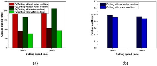
Figure 12.
Average cutting force and friction coefficient at different cutting speeds ((a) average cutting force at different cutting speeds (b) friction coefficient at different cutting speeds).
Therefore, when the cutting speed increases, the friction coefficient is larger regardless of whether there is water medium cutting. However, when cutting with water medium it is slightly smaller than when cutting without water medium, the friction between the tool and the workpiece is reduced, and the increase in the cutting speed reduces the interaction force between the tool and the workpiece. This shows that, within a certain range, appropriately increasing the cutting speed can not only improve the processing efficiency, but also reduce the friction between the workpiece and the tool.
Figure 13 shows the temperature distribution of the Newtonian layer at different cutting speeds; the cutting speed of the black and red lines is 100 m/s, and the cutting speed of the blue and green lines is 200 m/s. It can be seen from the figure that the temperature of the Newtonian layer varies with the cutting speed increase and rise. When the cutting speed is 100 m/s and cutting without water medium, the temperature of the Newton layer increases with the increase in cutting distance, and it fluctuates slightly around 460 K after stable cutting. When cutting with water medium, the temperature of the Newton layer fluctuates around 420 K and reaches equilibrium. When the cutting speed is 200 m/s and no water medium is used for cutting, the temperature of the Newtonian layer increases rapidly with the increase in the cutting distance, and then maintains a balance around 490 K; when cutting with water medium, the temperature of the Newtonian layer tends to balance at 450 K.
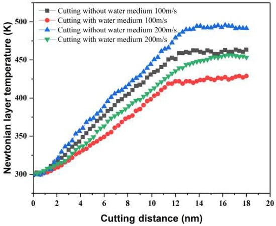
Figure 13.
Temperature distribution at different cutting speeds.
It can be seen from Figure 13 that during the increase in cutting speed, the temperature curve continues to slowly rise to a steady state, and the cutting distance at which the temperature of the Newtonian layer tends to balance is larger. On the one hand, with the increase in cutting speed, the atomic activity in the γ-TiAl alloy increases, and the increase in atomic kinetic energy converts the energy in the workpiece into more cutting heat, which affects the temperature distribution of the Newtonian layer. On the other hand, as the cutting speed increases, the time for the tool to travel the same cutting distance is shorter, resulting in a shorter time for heat transfer within the workpiece. Therefore, as the cutting speed increases, the Newtonian layer temperature increases.
3.5. Influence of Cutting Speed on Defect Evolution
Figure 14 shows the distribution of defect evolution under different cutting speeds, where Figure 14a,c show the subsurface defect distributions at cutting speeds of 100 m/s and 200 m/s, respectively, when cutting without water medium, and Figure 14b,d represent the subsurface defect distribution at cutting speeds of 100 m/s and 200 m/s, respectively, when cutting with water medium. It can be seen from the figure that with the increase in cutting speed, the difference in the evolution of defects in the workpiece is also different.
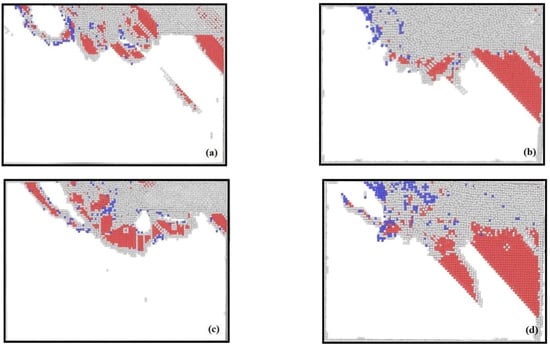
Figure 14.
Distribution of subsurface defects at different cutting speeds ((a) cutting speed is 100 m/s and without watermedium (b) cutting speed is 100 m/s and with watermedium (c) cutting speed is 100 m/s and without watermedium (d) cutting speed is 200 m/s and with watermedium).
Figure 14 shows the deletion of normal FCC atoms, with red for HCP atoms, blue for BCC atoms and grey-white for other atoms. It can be seen from Figure 14a,c that when cutting without water medium and the cutting speed is 100 m/s, the machined surface of the workpiece is well formed, and the subsurface generates less dislocation. When the cutting speed is 200 m/s, there are many defects in the workpiece and the emitted dislocations evolve into stacking faults, and there are more vacancy clusters and stacking faults on the machined surface. This is due to the increase in cutting force and cutting temperature when the cutting speed is high. This leads to the activation of more slip systems in the workpiece and the formation of more dislocation atoms.
When cutting with water medium, as the cutting speed increases, more BCC atoms are formed in the machined area under the tool inside the workpiece and in the advancing direction of the tool. Due to the existence of the aqueous medium, the plastic deformation of the γ-TiAl alloy is reduced, and the number of SISF increases. Moreover, with the increase in cutting speed, some subsurface atoms, stacking fault-slip systems and dislocations are removed with the chips before they are fully evolved due to the increase in cutting speed. Therefore, when the cutting speed increases, the number of a small amount of atomic groups inside the workpiece increases, and the stacking fault area increases. This is especially true when the medium is aqueous and the cutting speed is 200 m/s, which shows that the increase in the cutting speed can quickly remove chips to a certain extent. However, it still has a certain influence on the quality of the machined surface. Therefore, a reasonable choice of cutting speed is one of the important considerations to improve the quality of the machined surface.
Figure 15 counts the crystal structure transition curves at cutting speeds of 100 m/s and 200 m/s, respectively. Figure 15a,b represent the crystal structure transition curves during cutting without water medium and with water medium, respectively. Depending on the speed, the transformation of the atomic structure of the crystal varies. It can be seen from Figure 15a that when the cutting speed increases, the HCP atoms increase rapidly at first and then decrease. This is because when the cutting speed increases, the contact time between the tool and the workpiece in the same processing area is shortened, and the tool part of the atomic crystal structure at the front end is removed as chips before the lattice transformation occurs. Therefore, in the process of cutting without water medium, the number of HCP atoms decreases with the increase in cutting distance to the later stage of cutting, while the number of BCC atoms is basically maintaining a balance.
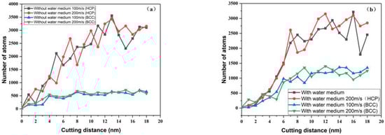
Figure 15.
Crystal structure transition curves at different cutting speeds ((a) without water medium (b) with water medium).
When cutting with water medium, the HCP atoms increased slowly from the beginning to the cutting stability and then fluctuated continuously with the increase in cutting distance. The number of BCC atoms increased more with the increase in cutting distance, as shown in Figure 15b. The number of BCC atoms during cutting is relatively small when without the water medium. This is due to the difference in the transformation of the lattice structure during the cutting process due to the difference in temperature; however, regardless of whether the cutting contains water or not, the change in the cutting speed has little effect on the number of HCP atoms. In general, there is relatively more nucleation and expansion of intrinsic stacking faults, so there are more HCP atoms and fewer BCC atoms.
3.6. Influence of Cutting Speed on Internal Stress
As far as the residual stress itself is concerned, the residual stress inside the workpiece can be regarded as a superimposed point source stress field with infinite continuous distribution. From a macroscopic point of view, every atom inside the workpiece may be a point source in the residual stress field of the workpiece. No matter whether the workpiece is processed or not, there will be residual stress on the surface and inside of the single crystal γ-TiAl alloy workpiece. In the process of micro-nano cutting, it is difficult to measure the residual stress of the simulated workpiece due to the unrealistic nature of the simulation. However, the internal stress of the workpiece during the cutting process can well describe the change in the internal stress of the workpiece during the cutting process. It can be seen from the foregoing that the presence of the water medium significantly increases the compressive stress during the cutting process.
On the one hand, due to the vigorous movement of the water medium, the collision between the water molecules and the workpiece atoms increases. Therefore, the direct contact area between the tool, water molecules and the workpiece increases, and there is obvious compressive stress distribution. On the other hand, the existence of water medium reduces the temperature distribution of the workpiece, thus increasing the compressive stress of the workpiece. This is also consistent with reducing the processing temperature and reducing the plastic deformation of the workpiece in macro cutting [37], so that there is more compressive stress in the workpiece.
Figure 16 is the internal stress distribution diagram when the cutting depth is 3 nm, and it is colored according to the value. Figure 16a,b are the internal stress distributions when the cutting speed is 100 m/s and 200 m/s, respectively, when cutting without water medium; Figure 16c,d show the internal stress distribution at cutting speeds of 100 m/s and 200 m/s, respectively, when cutting with water medium, that is, the hydrostatic stress distribution at different cutting depths.
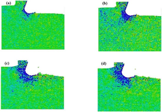
Figure 16.
Internal stress distribution at different cutting speeds ((a) cutting speed is 100 m/s and without watermedium (b) cutting speed is 200 m/s and without watermedium (c) cutting speed is 100 m/s and with watermedium (d) cutting speed is 200 m/s and with watermedium).
It can be seen from Figure 16 that when cutting without water medium, the compressive stress inside the workpiece gradually extends to the inside of the workpiece along the depth direction as the cutting speed increases. When the cutting speed is 100 m/s, the compressive stress mainly exists in the direct contact between the tool and the workpiece. In the contact area, there is no obvious tensile and compressive stress inside the processed workpiece, indicating that the internal stress change of the processed part is in a state of tension and compression balance. However, it can be clearly seen that there is compressive stress in the processing forward direction, which is due to the tool on the processing area. The extrusion of the atoms in the workpiece, and the hindering effect of the atoms inside the workpiece on the advancing tool, cause more compressive stress inside the workpiece. Therefore, when the cutting speed is 200 m/s, more compressive stress exists in the unmachined area of the front end of the workpiece and the shearing area between the tool and the workpiece.
When cutting with water medium, it can be clearly seen that the compressive stress shows the maximum compressive stress distribution in the processed area. On the one hand, due to the violent movement of water molecules, the shear deformation area at the front end of the tool forms more compressive stress due to the extrusion of the tool and the workpiece with water molecules. On the other hand, the machined surface is a surface with a cutting depth of 3 nm, it is also the most affected by the tool and the area with the highest local temperature in the system. Therefore, the maximum compressive stress distribution is exhibited under the action of thermomechanical coupling.
Comparing Figure 16a,d, it can be seen that with the increase in cutting speed, the stress distribution inside the workpiece presents two distributions. One is because the compressive stress on the machined surface is relatively high. The inside of the workpiece that has been machined is basically in a state of tension and compression balance. The other is because the compressive stress in the shearing area and in the front of the machining process increases with the increase in cutting speed. Since the presence or absence of water molecules in the two cutting systems lead to different temperatures, and the motion of atoms is closely related to temperature, the intensity of atomic motion leads to a certain difference in stress at the same depth. Therefore, considering the cooling effect of the cutting fluid from the processing point of view, the rational use of the cutting fluid can obtain better processing quality, reduce the cutting temperature, prolong the service life of the tool and reduce the processing cost.
4. Conclusions
In this paper, through the MD simulation of the nano-cutting process of single crystal γ-TiAl alloy with water medium in different machining parameters, the influence of machining parameters on the material removal process and subsurface defect evolution in aqueous medium is analyzed. The evolution of subsurface defects and the transformation of the crystal structure of the workpiece were studied by CNA method, and the change in cutting force, temperature distribution and stress change during machining were analyzed. The conclusions are as follows:
- (1)
- The cutting force increases gradually with the increase in the cutting depth; the friction between the tool and the workpiece is small when the water-containing medium is cut; and the friction coefficient decreases with the increase in the cutting depth. When the cutting speed increases from 100 m/s to 200 m/s, the friction between the tool and the workpiece is slightly smaller when the cutting medium is cut with water than when the cutting medium is cut without water. When the cutting speed is 100 m/s, the cutting force increases with the increasing of the cutting distance due to the shear action of the tool on the workpiece. When the cutting speed is 200 m/s, the cutting force fluctuation is the most obvious. Properly increasing the cutting speed can not only reduce the friction between the workpiece and the tool, but also improve the processing efficiency.
- (2)
- The temperature of the Newtonian layer increases with the increase in the cutting depth. The cooling of the water medium and the thermal balance of the constant temperature layer accelerate the conversion of the overall energy of the workpiece. The temperature of the Newtonian layer is relatively low during cutting, and the temperature of the Newtonian layer tends to increase as the cutting speed increases and the state of balance is further back. In the process of increasing the cutting speed from 100 m/s to 200 m/s, the temperature curve continues to rise slowly and then tends to a stable state, and the higher the cutting speed is, the later the Newtonian layer temperature reaches equilibrium.
- (3)
- During the cutting process with water medium, the HCP atoms slowly increased with the increase in cutting speed, gradually stabilized, and then changed continuously with the increase in cutting distance. The increase in cutting speed makes the subsurface defect evolve violently, BCC atoms increase, and there are more amorphous atoms on the machined surface.
- (4)
- The existence of water medium significantly increases the compressive stress in the cutting process, and the compressive stress of the machined surface is large. When the cutting speed is 100 m/s, the compressive stress mainly exists in the direct contact area between the tool and the workpiece. When the cutting speed is 200 m/s, there is more compressive stress in the unmachined area at the front of the workpiece and in the shear area between the tool and the workpiece. The presence of water medium increases the compressive stress significantly in the cutting process, and the compressive stress in the shear area and in the front of the machining process increases with the increase in the cutting speed. The compressive stress on the machined surface is larger, and the workpiece is in a state of tension and compression equilibrium.
Author Contributions
Conceptualization, N.D.; methodology, P.W. and J.L.; software, P.W.; formal analysis, P.W.; investigation, N.D. and P.W.; resources, S.M. and J.L.; data curation and writing—original draft preparation, P.W. and P.Y.; writing—review and editing, S.M. and J.L.; visualization, S.M. All authors have read and agreed to the published version of the manuscript.
Funding
This research was funded by a grant from the National Natural Science Foundation of China, grant number 52065036; and the Hongliu First-class Disciplines Development Program of Lanzhou University of Technology.
Informed Consent Statement
Informed consent was obtained from all subjects involved in the study.
Acknowledgments
The technical support of Gansu Province Supercomputer Centre is gratefully acknowledged.
Conflicts of Interest
The authors declare no conflict of interest.
References
- Hegab, H.; Darras, B.; Kishawy, H. Sustainability Assessment of Machining with Nano-Cutting Fluids. Procedia Manuf. 2018, 26, 245–254. [Google Scholar] [CrossRef]
- Krupa, K.; Habrat, W.; Kocurek, P.; Sieniawski, J. Surface residual stresses in finish turning of gamma titanium alloy TiAl (γ). Mechanik NR 2016, 10, 1508–1509. [Google Scholar] [CrossRef]
- Haiyan, L.; Haiyang, Q.; Ruicheng, F.; Qi, W.; Maomao, W.; Jianhua, L. Effect of cutting depth on mechanical properties of single crystal γ-TiAl alloy. Rare Met. Mater. Eng. 2020, 49, 1931–1937. [Google Scholar]
- Jianhua, L.; Cheng, Z.; Ruicheng, F.; Junjun, W.; Maomao, W.; Hai-yan, L.; Yongnian, Q.; Zhiyuan, R. Multiscale Model for Crack Propagation of gamma/gamma Interface in gamma-TiAl Alloy Based on Cohesive Zone Model. Rare Met. Mater. Eng. 2021, 50, 1617–1625. [Google Scholar]
- Fan, X.; Rui, Z.; Cao, H.; Fu, R.; Feng, R.; Yan, C. Nanoindentation of γ-TiAl with different crystal surfaces by molecular dynamics simulations. Materials 2019, 12, 770. [Google Scholar] [CrossRef]
- Feng, R.; Song, W.; Li, H.; Qi, Y.; Qiao, H.; Li, L. Effects of Annealing on the Residual Stress in γ-TiAl Alloy by Molecular Dynamics Simulation. Materials 2018, 11, 1025. [Google Scholar] [CrossRef]
- Li, J.; Sun, Y.; Xie, H.; Zhao, W.; Xu, C.; Liu, J. Effect of cutting parameters on the depth of subsurface deformed layers of single γ-TiAl alloy during nano-cutting process. Appl. Phys. A 2022, 128, 1–8. [Google Scholar] [CrossRef]
- Pervaiz, S.; Rashid, A.; Deiab, I.; Nicolescu, M. Influence of Tool Materials on Machinability of Titanium- and Nickel-Based Alloys: A Review. Mater. Manuf. Process. 2014, 29, 219–252. [Google Scholar] [CrossRef]
- Li, Y.; Shuai, M.; Zhang, J.; Zheng, H.; Sun, T.; Yang, Y. Molecular Dynamics Investigation of Residual Stress and Surface Roughness of Cerium under Diamond Cutting. Micromachines 2018, 9, 386. [Google Scholar] [CrossRef]
- Chen, Y.; Han, H.; Fang, F.; Hu, X. MD simulation of nanometric cutting of copper with and without water lubrication. Sci. China Technol. Sci. 2014, 57, 1154–1159. [Google Scholar] [CrossRef]
- Fang, F. Atomic and close-to-atomic scale manufacturing: Perspectives and measures. Int. J. Extreme Manuf. 2020, 2, 030201. [Google Scholar] [CrossRef]
- Bewlay, B.P.; Weimer, M.; Kelly, T.; Suzuki, A.; Subramanian, P. The Science, Technology, and Implementation of TiAl Alloys in Commercial Aircraft Engines. MRS Proc. 2013, 1516, 49–58. [Google Scholar] [CrossRef]
- Kara, F.; Aslantaş, K.; Cicek, A. Prediction of cutting temperature in orthogonal machining of AISI 316L using artificial neural network. Appl. Soft Comput. 2016, 38, 64–74. [Google Scholar] [CrossRef]
- Kara, F.; Aslantas, K.; Çiçek, A. ANN and multiple regression method-based modelling of cutting forces in orthogonal machining of AISI 316L stainless steel. Neural Comput. Appl. 2014, 26, 237–250. [Google Scholar] [CrossRef]
- Liang, L.; Xiaojing, Y.; Ning, L.; Ruiwen, G. Nano-cutting Temperature Field Distribution and the Influence of Anisotropy on Cutting Temperature of Single Crystal Germanium. Rare Met. Mater. Eng. 2019, 48, 1130–1134. [Google Scholar]
- Wang, Y.; Shi, J. Effects of water molecules on tribological behavior and property measurements in nano-indentation processes—A numerical analysis. Nanoscale Res. Lett. 2013, 8, 389. [Google Scholar] [CrossRef] [PubMed]
- Ishii, N.; Tanaka, R.; Kojima, Y.; Sekiya, K.; Yamada, K.; Koseki, S. Influence of the Cutting Fluid on Tool Edge Temperature in End Milling of Titanium Alloy. Key Eng. Mater. 2015, 656–657, 296–301. [Google Scholar] [CrossRef]
- Zhao, W.; Ren, F.; Iqbal, A.; Gong, L.; He, N.; Xu, Q. Effect of liquid nitrogen cooling on surface integrity in cryogenic milling of Ti-6Al-4 V titanium alloy. Int. J. Adv. Manuf. Technol. 2019, 106, 1497–1508. [Google Scholar] [CrossRef]
- Rentsch, R.; Inasaki, I. Effects of Fluids on the Surface Generation in Material Removal Processes: —Molecular Dynamics Simulation–. CIRP Ann. 2006, 55, 601–604. [Google Scholar] [CrossRef]
- Shimada, S.; Ikawa, N.; Tanaka, H.; Ohmori, G.; Uchikoshi, J.; Yoshinaga, H. Feasibility Study on Ultimate Accuracy in Microcutting Using Molecular Dynamics Simulation. CIRP Ann. 1993, 42, 91–94. [Google Scholar] [CrossRef]
- Pasam, V.K.; Neelam, P. Effect of Vegetable Oil–Based Hybrid Nano-Cutting Fluids on Surface Integrity of Titanium Alloy in Machining Process. Smart Sustain. Manuf. Syst. 2020, 4, 1–18. [Google Scholar] [CrossRef]
- Wang, Q.; Feng, R.; Fan, L.; Shao, Z.; Dong, J. Effect of cutting depth on subsurface defects and residual stress of single crystal γ-TiAl alloy. Mater. Rev. 2021, 35, 14089–14095. [Google Scholar]
- Brańka, A.C. Nosé-Hoover chain method for nonequilibrium molecular dynamics simulation. Phys. Rev. E 2000, 61, 4769–4773. [Google Scholar] [CrossRef] [PubMed]
- Wang, Y.C.; Wu, C.Y.; Chung, I.H. Chung, Comparison studies of large-scale conventional molecular dynamics simulation on parallel machines. In Proceedings of the 2012 IEEE 14th International Conference on High Performance Computing and Communication & 2012 IEEE 9th International Conference on Embedded Software and Systems 2012, Liverpool, UK, 25–27 June 2012; pp. 959–963. [Google Scholar]
- Zhu, Y.; Zhang, Y.C.; Guo, J.Y.; Qi, S.H.; Xiang, Z. Molecular dynamics study of the effects of tool geometric parameters on titanium nanometric cutting. Mach. Tool Hydraul. 2015, 43, 44–50. [Google Scholar]
- Liang, Y.C.; Wang, Q.L.; Chen, J.X.; Xie, W.K.; Sun, Y.Z. Molecular Dynamics Simulation Research in Water Adsorption on Aluminum Surface. Key Eng. Mater. 2013, 562–565, 1308–1313. [Google Scholar] [CrossRef]
- Wen, Y.; Zhu, R.Z.; Zhou, F.X.; Wang, C.Y. Main techniques of molecular dynamics simulation. Adv. Mech. 2003, 1, 65–73. [Google Scholar]
- Dong, G.Y.; Xiao, Z.Z.; Guang, Z.Y.; Sun, Y. Research on the nanometric machining of a single crystal nickel via molecular dynamics simulation, Science China. Technol. Sci. 2016, 59, 1837–1846. [Google Scholar]
- Daw, M.S.; Baskes, M.I. Semiempirical, Quantum Mechanical Calculation of Hydrogen Embrittlement in Metals. Phys. Rev. Lett. 1983, 50, 1285–1288. [Google Scholar] [CrossRef]
- Daw, M.S.; Baskes, M.I. Embedded-atom method: Derivation and application to impurities, surfaces, and other defects in metals. Phys. Rev. B 1984, 29, 6443–6453. [Google Scholar] [CrossRef]
- Morse, P.M. Diatomic Molecules According to the Wave Mechanics. II. Vibrational Levels. Phys. Rev. (Ser. I) 1929, 34, 57–64. [Google Scholar] [CrossRef]
- Lennard-Jones, J.E. Classification of Inflammatory Bowel Disease. Scand. J. Gastroenterol. 1989, 24, 2–6. [Google Scholar] [CrossRef] [PubMed]
- Baowan, D.; Triampo, W.; Triampo, D. Encapsulation of TiO2 nanoparticles into single-walled carbon nanotubes. New J. Phys. 2009, 11, 093011. [Google Scholar] [CrossRef]
- Li, H.Y.; Feng, R.C.; Cao, H. Effects of Vacancy on Mechanical Properties of Single-Crystal gamma-TiAl based on Molecular Dynamics Simulation. In Proceedings of the 4th 2016 International Conference on Material Science and Engineering (ICMSE 2016), Guangzhou, China, 17–19 June 2016; Atlantis Press: Amsterdam, The Netherlands, 2016; pp. 175–181. [Google Scholar]
- Kitamura, T.; Umeno, Y.; Ohtani, R. Molecular Dynamics Study on Grain Boundary Diffusion in Aluminum under Hydrostatic Stress. JSME Int. J. Ser. A 1998, 41, 10–15. [Google Scholar] [CrossRef]
- Klocke, F.; Settineri, L.; Lung, D.; Priarone, P.C.; Arft, M. High performance cutting of gamma titanium aluminides: Influence of lubricoolant strategy on tool wear and surface integrity. Wear 2013, 302, 1136–1144. [Google Scholar] [CrossRef]
- Lei, C.; Feng, R.; Shao, Z.; Li, H.; Cao, H. Effect of cryogenic nano-cutting on surface integrity of the single crystal γ-TiAl alloy via atomic simulation. Appl. Phys. A 2022, 128, 1–16. [Google Scholar] [CrossRef]


Publisher’s Note: MDPI stays neutral with regard to jurisdictional claims in published maps and institutional affiliations. |
© 2022 by the authors. Licensee MDPI, Basel, Switzerland. This article is an open access article distributed under the terms and conditions of the Creative Commons Attribution (CC BY) license (https://creativecommons.org/licenses/by/4.0/).