Article

Assessment of the Effect of Residual Stresses Arising in the HAZ of Welds on the Fatigue Life of S700MC Steel

Department of Engineering Technology, Faculty of Mechanical Engineering, Technical University of Liberec, Studentská 1402/2, 46117 Liberec, Czech Republic
*
Author to whom correspondence should be addressed.
Metals 2022, 12(11), 1890; https://doi.org/10.3390/met12111890
Submission received: 20 October 2022 / Revised: 2 November 2022 / Accepted: 3 November 2022 / Published: 4 November 2022
(This article belongs to the Special Issue Fatigue Assessment of Metal Welded Joints)

Abstract

:
Fine-grained steels, which belong to the HSLA (High-Strength Low-Alloy) group of steels, are increasingly used for parts of statically and dynamically loaded constructions. Due to the thermal effect of welding, combined with the inherent stiffness and clamping stiffness of the part, residual stresses are generated in the HAZ (heat-affected zone) which affect the fatigue life of the sub-weld and the entire construction. In this article, a specific temperature cycle measured during welding is used, which, together with a defined clamping stiffness, produces residual stresses of a defined shape and value in the sample. Subsequently, the effect of these stresses on the fatigue life on the change of the S–N curve compared to the annealed material, is assessed. Temperature cycles were applied using a Gleeble 3500 and the residual stresses were analyzed by X-ray diffraction (XRD). It was found that the effect of residual stresses decreased the fatigue strength by 33% compared to the annealed material. It was further found that by using annealing to reduce the residual stresses, it is possible to restore the fatigue life of S700MC steel to the original value of the base material.

1. Introduction

High-Strength Low-Alloy steels (HSLA) are used in the construction of bridges, and oil and gas platforms but also in the manufacture of wind generator supports, ships, statically and dynamically loaded components or high-pressure vessels [1,2,3]. Nowadays, it is desirable to reduce material consumption, which can be solved in manufactured components by increasing the strength of the steel used while reducing the load-bearing cross-sections and, accordingly, the weight of the structure [4,5]. HSLA steels, with an excellent combination of strength, weldability and toughness, were developed to replace conventional medium carbon steels. These properties are achieved even with small amounts of alloying elements used, which satisfies the requirements for low prices that increase with increasing amounts of alloying elements. Due to microalloying and strictly controlled chemical composition, HSLA steel has very good cold formability and stable processability [4,5].
HSLA steels have a fine-grained structure, which is provided by the thermo-mechanical control method (TMCP) [3]. In order to reach the above steel properties, the steel is micro-alloyed with small contents of Ti, V, Nb, which form fine precipitates at the grain boundaries. These precipitates strengthen the metal matrix and refine the grains and, in steels with yield strengths of up to 700 MPa, are one of the main mechanisms for achieving the required strength properties of the steel [6,7,8]. Thermo-mechanically processed steels can have higher yield strength and other strengthening mechanisms, such as austenite to martensite and bainite phase transformation, are also used to strengthen these steels [9,10,11,12,13].
Fine-grained steels are easily weldable due to the small amount of alloying elements and especially the low carbon content. When welding HSLA steels, the heat input must be limited to 10 kJ·cm−1. The reason for the reduction of the heat input value is the intense grain coarsening in the HAZ and, for higher-strength steels, the softening of the structure, which can occur at the interface between the HAZ and the base material. Many studies have investigated grain coarsening and its effect on mechanical properties. For example, Bayock et al. [13] investigated the effect of heat input on the microstructure and mechanical properties of dissimilar S700MC/S960QC steels. Three different heat input values (15, 7 and 10 kJ·cm−1) were used. The best microstructure formation was obtained using a heat input of 10 kJ·cm−1. The S700MC steel was investigated by Górka [14] and also by Moravec et al. [15]. The aim of these studies was to determine the properties and microstructure of the HAZ of S700MC steel. The steel with higher strength properties was investigated by Mičian et al. [16]. In the study, the effect of the cooling rate on the mechanical properties of the heat-affected zone of the steel S960MC was investigated. Furthermore, Jambor et al. [17] dealt with the development of the microstructure in the HAZ of the S960MC steel GMAW weld.
Simulations of welding processes were studied by Kik [18], who presented a comparison of modern computer techniques. The results of calculations of displacements and stress distributions in the welded joints using various computational techniques were compared. Kik [19] also discussed new possibilities for modifying heat-source models in numerical simulations of laser welding processes.
Stress concentration factors (SCF) were studied by Nassiraei and Rezadoost [20,21]. They studied the SCF in circular X-connections and in tubular T/Y-connections containing FRP (fiber-reinforced polymer). They also studied [22,23] factors (SCFs) in FRP-reinforced CHS T/Y-connections under an in-plane bending moment and under an out-of-plane bending load.
A number of publications were also published for the assessment of the effect of cyclic loading on HSLA steels. In this field, the fatigue of MAG-welded joints in HSLA steels was investigated by, e.g., Lahtinen et al. [24] for S700MC steel, Kim et al. [25] for CT100+ steel and Lago et al. [26] for S960MC steel. The assessment of the effect of heat input on the fatigue life of welded joints was investigated by Šebestová et al. [27] for Hybrid Laser-TIG Welding and by Moravec et al. [28] for MAG welds. All of the above-mentioned authors comprehensively considered the influence of welding on fatigue life and therefore it is not possible to easily quantify the influence of partial aspects of the welding process. Detailed knowledge of the residual stress magnitude profile is required to accurately assess the effect of residual stresses in the HAZ on fatigue life. That residual stresses have an effect on fatigue life was confirmed by, e.g., Hong et al. [29] and Webster et al. [30]. James et al. [31] showed in their work that it is possible to incorporate residual stress information more routinely into fatigue life prediction, which was also confirmed by Lee and Chang [32]. Harati et al. [33] investigated the effects of residual stresses and weld toe geometry on the fatigue life of cross welds. He concluded that residual stresses have a greater effect on fatigue life than weld toe geometry.
The research presented in this article is focused on the influence of residual stresses generated in the HAZ on the fatigue life of parts. The residual stresses were determined using a non-destructive XRD method [34], which allows the samples to be used for further testing. The XRD method [35,36,37,38,39] is based on X-ray diffraction. The diffraction (scattering) takes place on the crystals of the material and the changes in the distances of the atomic lattice planes are measured. Changes in these distances are reflected by changes in the angle θ of the diffracted X-rays. The detected deformations, or changes in the distances of the lattice planes, are then recalculated to stresses.

2. Materials and Methods

Fine-grained steel S700MC according to ISO 10027-1 [40] and 1.8974 according to ISO 10027-2 [41] was used for the experiment. This material is a high-strength steel that is micro-alloyed and thermo-mechanically rolled. It is a steel with a guaranteed yield strength of at least 700 MPa, good cold formability, weldability, low carbon content, and reduced sulfur content. The steel is micro-alloyed with elements such as Al, Ti, V and Nb, and the sum of Ti, V, Nb does not exceed 0.22 wt.%.
The steel was delivered in the form of a 10 mm thick plate. The chemical composition was determined using a Bruker Q4 Tasmann spectrometer (Karlsruhe, Germany). Measurements were performed at five different areas of the sample. Table 1 shows the average value of the five measurements and the chemical composition as defined by EN 10149-2.
The steel has a ferritic-bainitic structure, which is shown in Figure 1. The grain size was obtained using EBSD (Electron Back Scatter Diffraction) analysis at a scanning electron microscope (SEM) Tescan Mira 3 (Tescan Orsay holding a.s., Brno, Czech Republic). For EBSD analysis, an Oxford Symmetry detector (Oxford Instruments, High Wycombe, UK) with the following process parameters was used: high voltage HV = 15 kV, step size 0.25 µm, scanned area 300 × 300 µm. The mean grain size of 3.38 µm was determined by the electron microscope.
Mechanical properties of the tested material were measured by the static tensile test and results are shown in Table 2. Mechanical properties of the delivered material as YS (Yield Strength), UTS (Ultimate Tensile Strength), Ag and A80 were measured at room temperature—RT. The testing device TIRA Test 2300 (TIRA GmbH, Schalkau, Germany) was used. Static tensile test was performed according to standard EN ISO 6892-1 with loading rate 1 mm/min up to achieving YS and after that 15 mm/min. The mechanical properties of the annealed material at 550 °C were measured. The reason for the annealing was to eliminate the surface residual stresses in the sample that were created during the machining process. The annealing of the samples was carried out in a Reetz vacuum furnace (HTM Reetz GmbH, Berlin, Germany). The heating rate was the same for all experiments and was stepwise (0.8 °C·min−1 to 80 °C; 1.5 °C·min−1 to 220 °C; 2 °C·min−1 to 300 °C and 4 °C·min−1 in the temperature range 300 to 550 °C). The holding time at the annealing temperature was 2 h. Additionally, the cooling rate of the sample was the same for all experiments and in this case was constant (5 °C·min−1). The heat treatment was carried out under vacuum, which was 7 × 10⁻⁵ mbar. The determination of the residual stresses by XRD method confirmed that only minimal residual stresses were present in the annealed samples (550 °C for 2 h). Table 2 shows the average values of the mechanical properties of the base and annealed material obtained from 5 measurements.
Temperature cycles and boundary conditions, used as input data for physical simulations in the thermo-mechanical simulator Gleeble 3500 (Dynamic System Inc., New York, NY, USA), were obtained during real welding of butt welds performed by the MAG method. Welding experiments were performed on a Migatronic PulsSyn 550 (MIGATRONIC A/S, Fjerritslev, Denmark) with a machine torch clamped to a linear automat. The welding current was set at 260 A and the torch movement speed was 0.4 m-min-1. The process parameters were recorded by a WeldMonitor system (DIGITAL ELECTRIC, Brno, Czech Republic) with a recording frequency of 25 kHz. The WeldMonitor system recorded the actual welding parameters—current 260.8 A; voltage 25.6 V and welding speed 0.407 m·min−1. The temperature cycles in the HAZ of the welds were measured by the thermocouples type R, connected to a DiagWeld apparatus (Technical University of Liberec, Liberec, Czech Republic) with a recording frequency of 50 Hz.
For the experiments, special samples of square cross-sections were designed, see Figure 2. The test sample is designed in order to study in detail the residual stresses arising in the HAZ. As a result, not only sufficient heating rates but also the required cooling rates corresponding to real welding can be achieved in the working part of the sample. The threads at the ends are used to fix the sample against relative movement during the creation of stress (tensile, compressive stress) and it is, therefore, possible to define unambiguously the clamping boundary conditions corresponding to reality. The square cross-section of the sample was chosen so that there would be no need to compensate for scattering on the cylindrical surface during residual stress analysis by XRD method.
Physical simulations of welding were carried out in the thermo-mechanical simulator Gleeble 3500. The device allows heating of the sample at speeds up to 10,000 °C/s, which is sufficient for simulations of welding processes. By using suitable high-temperature grips and a free length of the sample between the grips, the correct temperature distribution and cooling rate can be achieved. For the experiment, copper high-temperature grips with full contact were chosen and the free length of the sample was 10 mm. To control the temperature cycle, a thermocouple type R to the sample center was welded. The boundary condition was defined as a rigid sample clamping with zero dilation monitored by an L-Gauge contact strain gauge. As a result, the sample could not dilate during heating, and the increasing force generated residual stresses in the sample, and the sample was plastically deformed when the yield stress value for a given temperature was exceeded.
Residual stresses were analyzed by X-ray diffraction using a PROTO iXRD COMBO (Proto Manufacturing Inc., Ontario, Canada). The tested steel was ferritic-bainitic and therefore a chromium X-ray tube (Voltage 25 kV, Current 4 mA, Wavelength Kα = 2.293606 A) was used for residual stress analysis. The X-ray elastic constants 𝑠1 = −1.25 TPa−1 and ½𝑠2 = 5.75 TPa−1 were used to convert deformation to stress. The value of the diffraction angle of the {211} α–Fe planes of the material in the undeformed state is 156° 2θ. These values were used from the XDR Win2000 software database. The diffraction angles were determined by the Gaussian function approximation using the Absolute Peak method. The algorithm for calculating the residual stresses was sin2 ψ.
Cyclic loading and fatigue properties measurements were performed on the servo-hydraulic device INOVA FU-O-1600-V2 (INOVA GmbH, Bad Schwalbach, Germany), in controlled force mode with alternating symmetrical loading with cycle asymmetry R = −1 and at a loading frequency of 20 Hz. For all experiments, samples with a circular cross-section were used, in accordance with standard EN 3987—see Figure 3.

3. Experiments and Results

In the experimental work, it was necessary to ensure the interdependence of activities so that they logically followed each other. Therefore, the following sub-steps were realized:
(1)
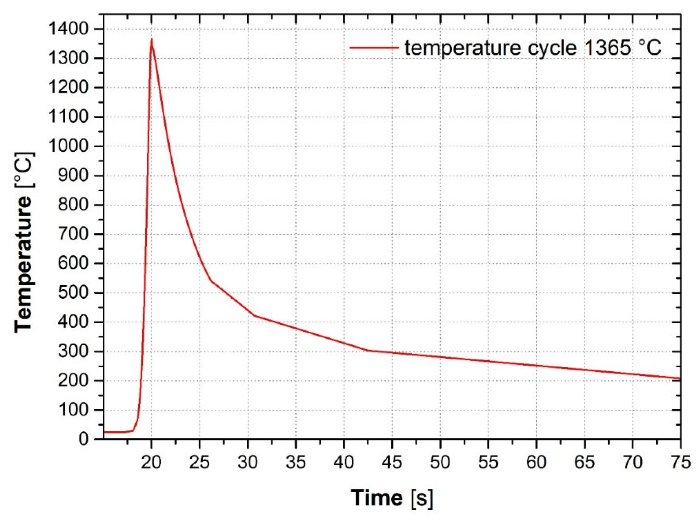
Obtaining a real temperature cycle corresponding to MAG welding with heat input up to 10 kJ·cm−1;
(2)
Experimental setting of the annealing conditions (T = 550 °C; t = 2 h) at which the surface residual stresses created during the machining of the test samples are reduced;
(3)
Determination of mechanical properties and S–N curves for the base and annealed materials;
(4)
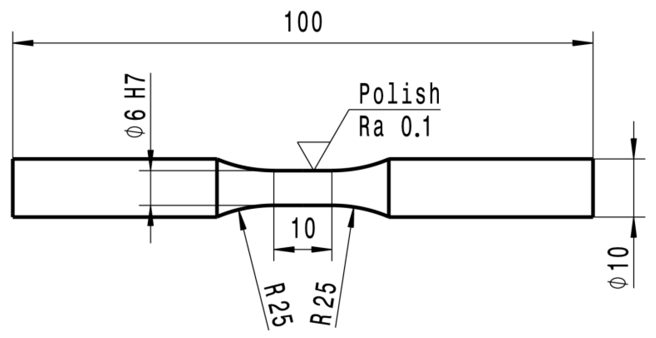
Application of a temperature–stress cycle to annealed samples (produced in accordance with Figure 2) in a Gleeble 3500;
(5)
Determination of the residual stresses in the samples using the XRD method;
(6)
Annealing to reduce residual stresses after application of temperature–stress cycle in device Gleeble 3500 realized for some samples;
(7)
Determination of S–N curves for the state corresponding to the influence of the temperature–stress cycle (with residual stresses) and also for the state after application of the temperature–stress cycle but with subsequent annealing to reduce residual stresses.

3.1. Measurement and Application of Temperature Cycles

For the simulation of processes that take place in the HAZ of the weld, it is necessary for these to be based on real welding conditions. Therefore, it is necessary to obtain the temperature cycle close to the fusion line, which is very difficult because everything depends on the accuracy of the thermocouple location close to the assumed fusion line. For this reason, a temperature field mapping experiment was prepared in the HAZ using a series of thermocouples offset from each other by 0.15 mm. Two plates of size 300 × 150 × 8 mm were prepared. The weld was assembled with a weld gap of 1.2 mm and a depth of root face of 1.5 mm. The included angle was 60°. The prepared samples were welded by the MAG method in the PA—flat position. As a filler material, Boehler UNION NiMoCr (BÖHLER Welding Group GmbH, Düsseldorf, Germany) was used, with a diameter of 1.2 mm and shielding gas M21. During the MAG welding, some of the thermocouples overflowed, but due to the defined offset of the individual thermocouples to each other, a temperature cycle with a maximum temperature of 1365 °C was obtained. The metallographic analysis determined that this was 0.96 mm away from the fusion line. Figure 4 shows the obtained temperature cycle as applied to the samples in the Gleeble 3500.

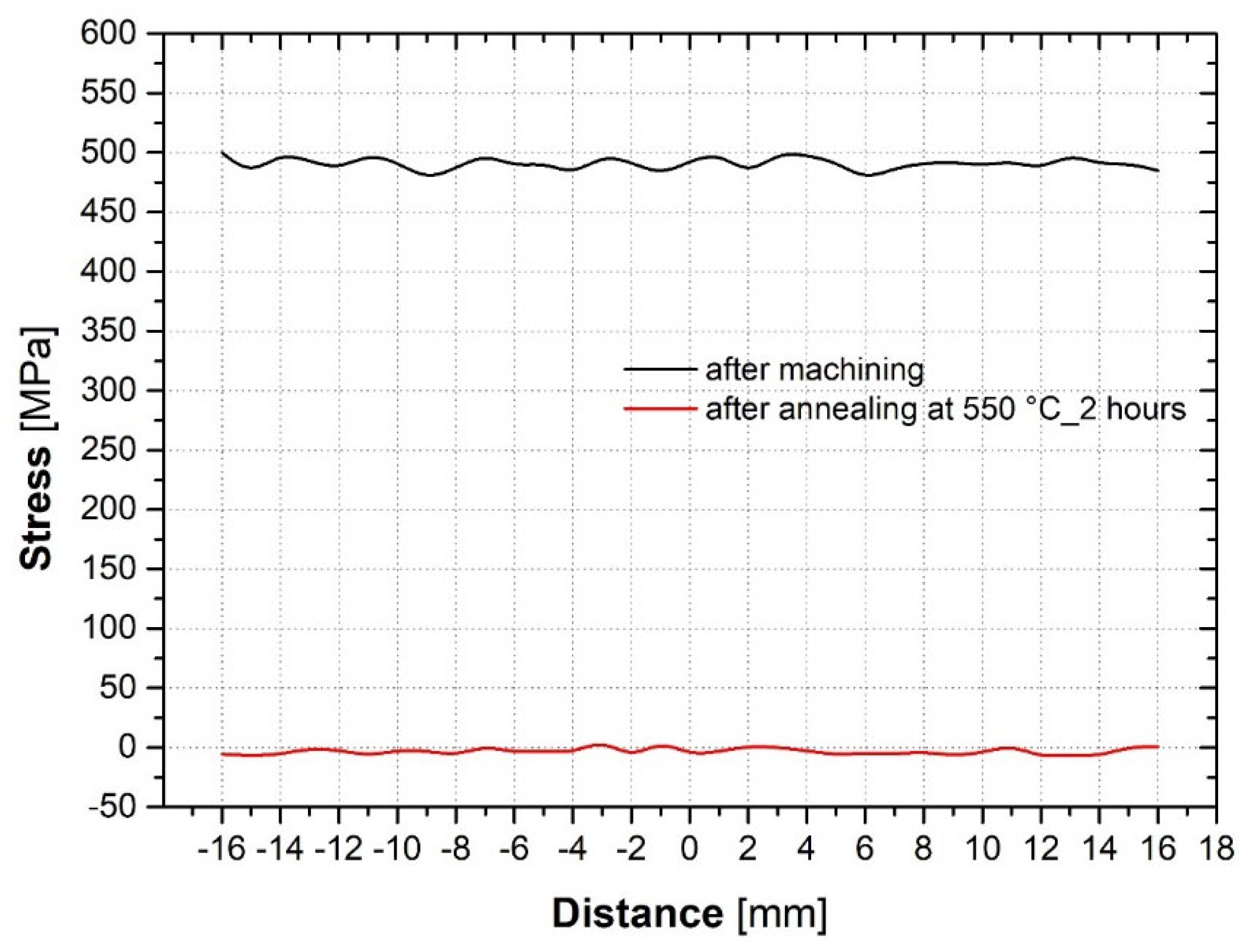
3.2. Analysis of Residual Stresses after Machining and after Annealing

The manufacturing of samples using machining creates stresses in the surface layers. Diffraction measurements were performed for sub-areas of 1 mm diameter, with a mutual mean distance of 1 mm between the measurement points. In total, 33 measurement points were measured for each variant. The results of the XRD analysis of the residual stresses after machining of the samples showed tensile stresses oscillating around a value of 485 MPa. By testing the annealing conditions, it was found that at a temperature of 550 °C and a holding time of 2 h, the residual stresses in the surface layer are reduced to almost zero. The results of the XRD analysis are shown in Figure 5.

3.3. Determination of S–N Curve for Base Material S700MC and Annealed Material

In the first step, the S–N curves of the base material, the delivered S700MC steel and the steel annealed in a vacuum furnace at 550 °C for 2 h, were determined. Cyclic loading of all samples produced in accordance with Figure 3 was carried out by alternating symmetrical loading with cycle asymmetry R = −1. The magnitude of the stress amplitude was kept constant for each stress level, at a loading frequency of 20 Hz. The criterion for termination of the test was fatigue crack initialization or exceeding the limit of 107 cycles. A total of 10 samples were tested for each variation—one sample for each stress level. The base material was tested at stress levels of 580; 550; 527.5; 505; 490; 475; 468; 461; 455 and 447.5 MPa and for the annealed material, stress levels of 580; 565; 550; 546; 542.5; 535; 527.5; 520; 500 MPa were chosen. The measured S–N curves of the base and annealed material are shown in Figure 6. The achieved fatigue life of the base material was σc = 447.5 MPa and the achieved fatigue life of the heat-treated material was σc = 500 MPa. Table 3 shows the fatigue test results for the base and annealed materials.

3.4. Application of Temperature Cycles in the Gleeble 3500

When the temperature–stress cycle was applied to the sample, first a thermocouple was welded to the center of the sample to control the heating and cooling temperatures. The welding was performed with capacitor welding and for the control, a thermocouple type R was used. The free length of the sample between the copper grips was 10 mm. The whole composition of the experiment is shown in Figure 7. The experiment was conducted in a vacuum of 3 × 10⁻³ Torr in a controlled deformation mode. A rigid clamping of the sample was defined with zero dilation monitored by the L-Gauge contact strain gauge. This procedure was repeated for all 20 test samples so that the distribution and magnitude of residual stresses were the same in all samples.
Fine-grained steels are very prone to grain growth in the HAZ and therefore the heat input must be limited in these steels. For this reason, EBSD analysis was performed from the center of the sample towards the edge. A total area of 0.6 × 4 mm was scanned. This analysis is used to determine the grain size in the most overheated area. A detail of the grain growth is shown in Figure 8, the left side of the figure corresponding to the center of the sample at 1365 °C. Grain growth in the HAZ of the weld was evaluated in three different, partially overlapping areas. As a result, mean grain sizes of d1 = 13.24 µm, d2 = 13.09 µm and d3 = 13.28 µm were obtained. The average mean grain size in the highly heated area is ds = 13.21 µm.

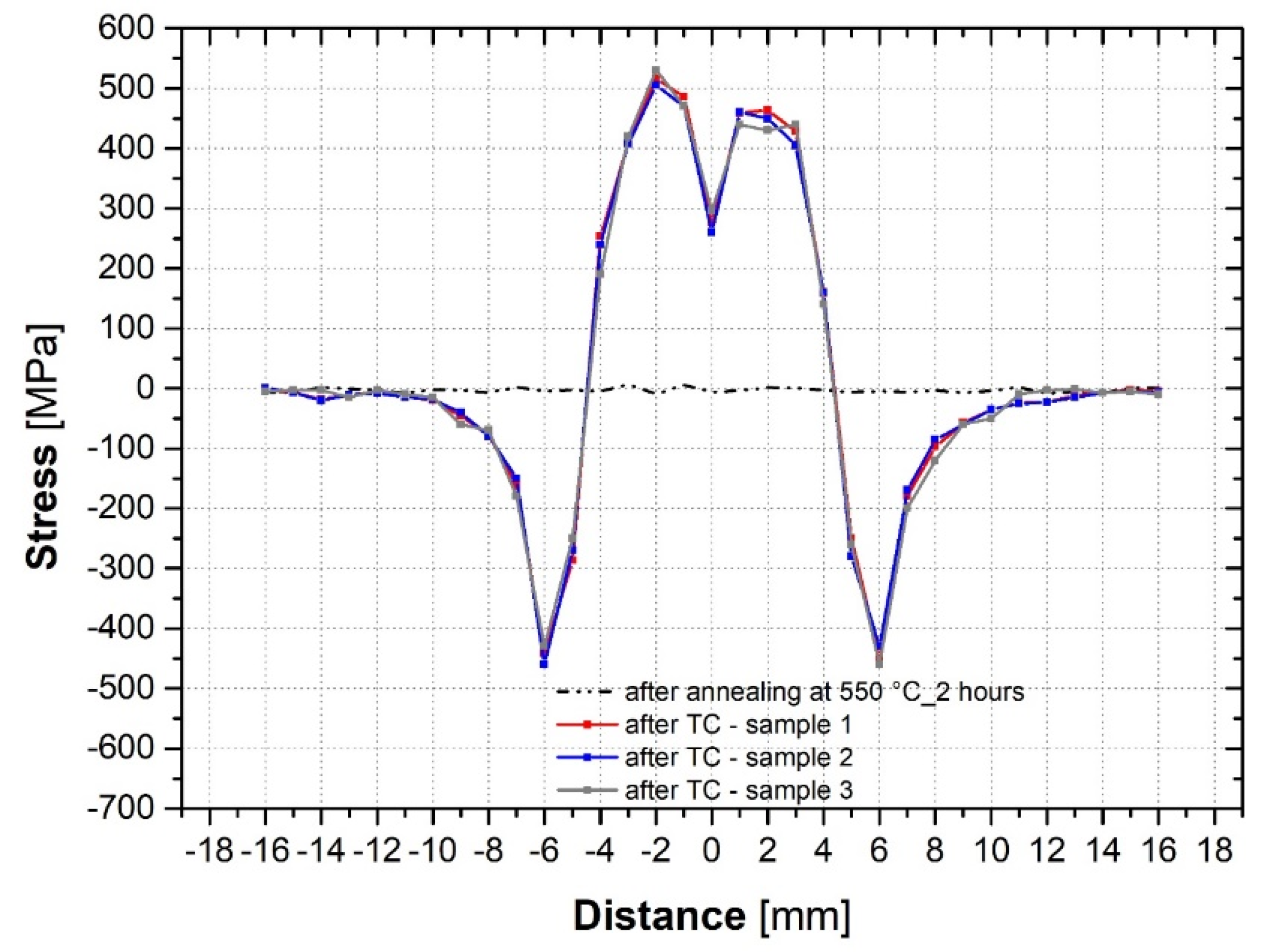
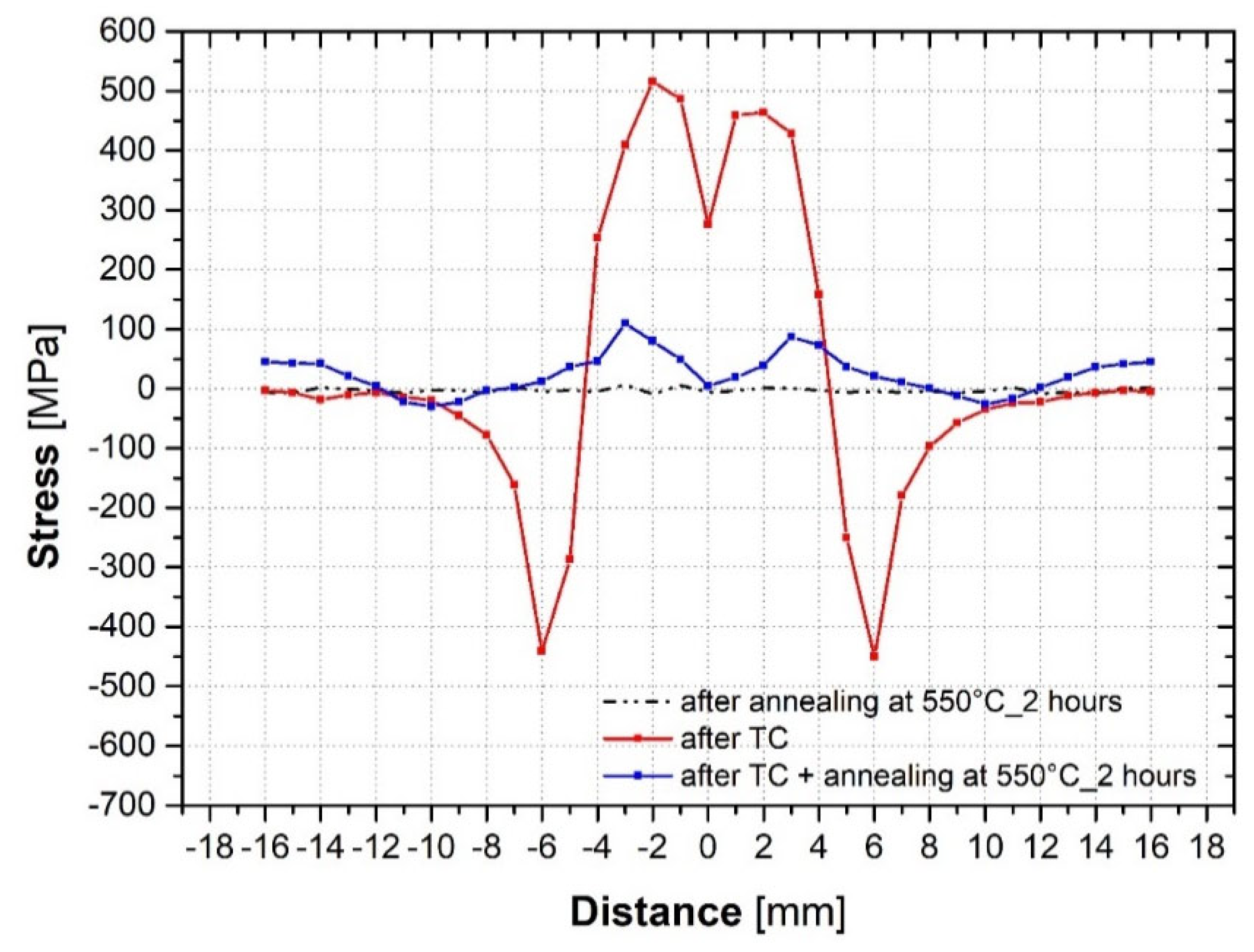
3.5. Analysis of Residual Stresses after Application of the Temperature–Stress Cycle

After the application of the temperature–stress cycles in the Gleeble 3500, it was possible to determine the magnitude and distribution of residual stresses in the samples. Diffraction measurements of the base material were made for sub-areas of 1 mm diameter, with a mean distance of 1 mm between the measurement points. In total, 33 measurement points were measured for each variant. Comparison of the magnitude and distribution of the residual stresses in the individual samples also confirmed the repeatability of the experiment in the device Gleeble. The courses of residual stresses, as determined by XRD for the three selected samples, are shown in Figure 9.
Figure 9 shows that the courses of residual stress are almost identical. The residual tensile stresses are approximately 300 MPa at the point of highest temperature, further from the center the tensile stresses increase up to 500 MPa to smoothly transition to compressive stress peaks at ±6 mm from the center of the sample.
From a total of 20 samples with residual stresses, 10 samples were subjected to annealing to reduce residual stresses so that the effect on fatigue life could be evaluated even after the elimination of residual stresses. The same conditions were chosen for the initial annealing (550 °C for 2 h). The courses of the detected residual stresses are shown in Figure 10. It is obvious that the above annealing conditions were able to reduce the residual tensile stresses by 80% and almost eliminate the residual compressive stresses.

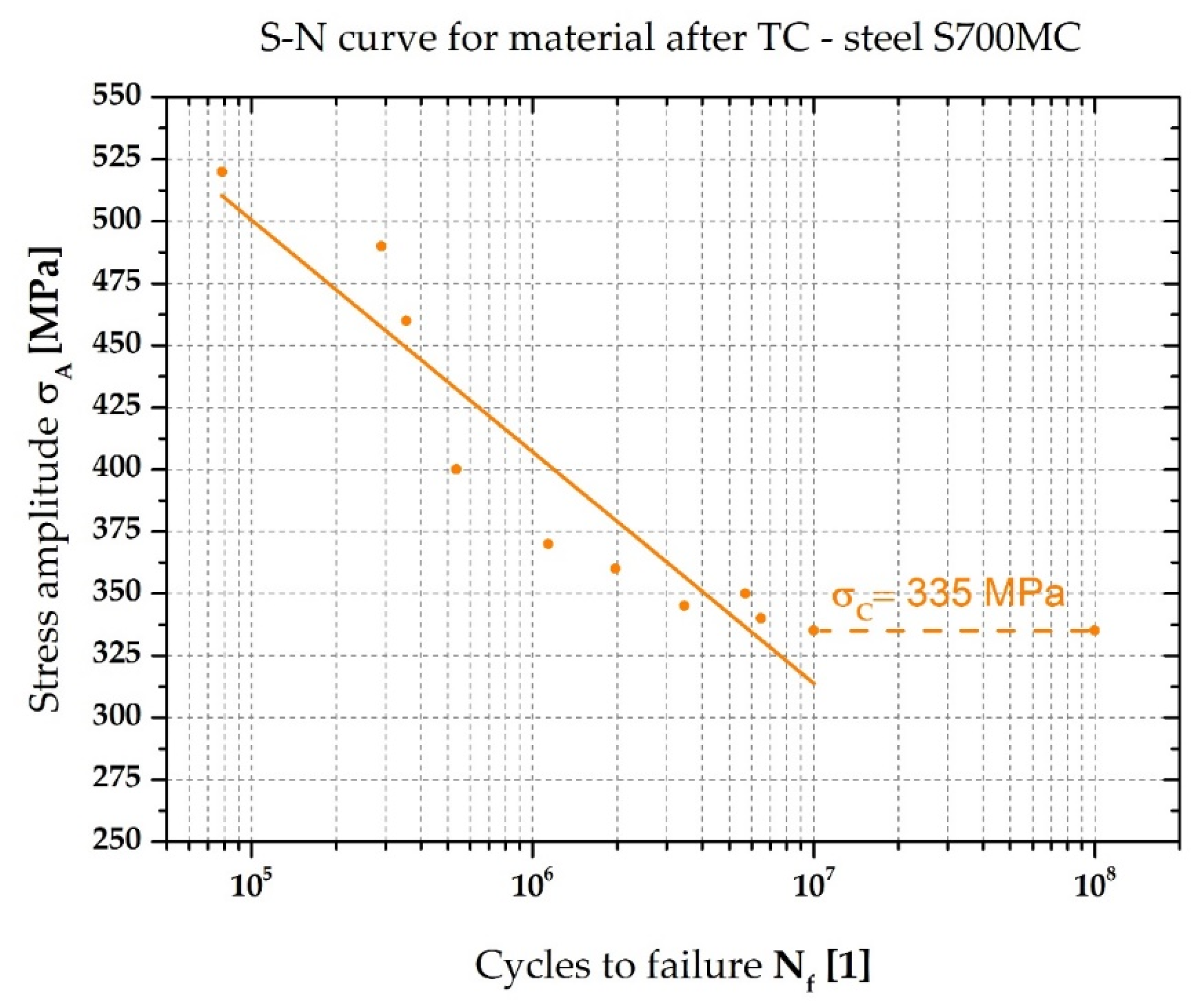
3.6. Fatigue Life Determination of Samples with Residual Stresses

In the final step, samples were cyclically tested after the application of temperature–stress cycles in the device Gleeble 3500. As in the previous cases, alternating symmetrical loading was applied to the samples with a cycle asymmetry of R = −1. The magnitude of the stress amplitude was kept constant for each stress level, at a loading frequency of 20 Hz. The criterion for termination of the test was fracture of the sample or exceeding the limit of 107 cycles. The samples were loaded at stress levels of 520; 490; 460; 400; 370; 360; 350; 345; 340 and 335 MPa. Again, a total of 10 samples were tested, one for each stress level. The fatigue test results for the samples with residual stresses are shown in Table 4 and the S–N curve is shown in Figure 11.
The effect of annealing to reduce residual stresses on the fatigue properties of S700MC was also investigated. Thus, a temperature–stress cycle was applied to the samples and then the samples were annealed in a vacuum furnace at 550 °C for 2 h. The results of the fatigue tests of these samples are shown in Table 5 and the S–N curve is shown in Figure 12. The stress levels chosen for these tests were 600; 570; 540; 500; 490; 480; 472.5; 465; 457.5; 450 MPa and the other test conditions were identical to the previous experiments.

4. Discussion

The fatigue life and the fatigue strength value σc are basic and important material characteristics for dynamically loaded parts. The use of HSLA steels in automotive applications requires information about the fatigue life of these steels. It is easier to obtain S–N curves of base materials than to obtain S–N curves of materials affected by a technological process such as welding.
A lot of publications deal with the study of the fatigue life of welds in HSLA steels [24,25,26,27]. However, these studies have comprehensively considered the effect of welding on fatigue life and therefore it is not possible to easily quantify the effect of partial aspects of the welding process. Detailed knowledge of the course of residual stresses in the HAZ is required to accurately assess the effect of residual stresses on fatigue life. That residual stresses have an effect on fatigue life was confirmed, for example by Hong et al. [29], who investigated the effect of weld-induced residual stresses on the fatigue behavior of a T-joint, and Webster et al. [30], who analyzed residual stresses by neutron diffraction and studied their redistribution. The study of partial influences of welding on fatigue life was studied by Moravec et al. [42]. In his work, he defined, for a double fillet weld, the percentage influence of the notch effect of the weld and the angular distortion during welding on the fatigue life. The residue was evaluated, as the cumulative effect of residual stresses and structural changes in the HAZ.
The experiment described in this work can assess the partial effects of changes occurring in the HAZ of welds on fatigue life and fatigue strength. By experimentally measuring the S–N curves for the condition of the sample with structural changes and knowing the residual stress distribution (Figure 11) and for the condition where the residual stresses in the sample were eliminated or at least significantly reduced (Figure 12), only the effect of residual stresses can be assessed. The remaining difference between the S–N curve for the annealed material (T = 550 °C; t = 2 h) and the S–N curve for the samples with TC applied and subsequently annealed at 550 °C for 2 h, is attributed to the structural changes that occur in the HAZ welds. HSLA steels are micro-alloyed and the effect of welding on microstructural changes is therefore only partial. By measuring the hardness across the sample, it was found that the hardness values changed very little. In the area of the sample corresponding to the HAZ, there was first an increase in hardness from an average value of 273 ± 3.2 HV to a maximum hardness value of 297 HV, i.e., an 8% increase in hardness. Then, at the place with the highest temperatures, there was a decrease in hardness to 266 HV. The structural changes were therefore very small. In our opinion, grain coarsening and also dislocation recovery of the material at the highest temperature areas will have a larger effect on the fatigue strength. This hypothesis is also supported by the fatigue strength results achieved for the material annealed at 550 °C for 2 h. A complete comparison of all measured S–N curves are shown in Figure 13.
Annealing the base material at 550 °C for 2 h had no effect on the change in YS, or this change was in tolerance of the measurement deviation. In terms of UTS, the value decreased by less than 8%. However, in terms of fatigue strength, there was an increase in σc of 10%, from 447.5 MPa to 500 MPa. EBSD analysis confirmed that there was no increase in the mean grain size.
The application of the temperature–stress cycle caused tensile and compressive residual stresses in the test samples, as seen in Figure 9, and caused an almost fourfold increase in the mean grain size in the highly heated area. As a result, the fatigue strength σc was decreased to 335 MPa, i.e., by 33% compared to the annealed material.
The samples were loaded to failure. Figure 14 shows that the sample did not fracture in the center, at the area of highest temperature and greatest grain coarsening, but 3.7 mm from the center of the sample, which corresponds to a location with tensile stresses of approximately 320 MPa. Similar fracture locations were found in the other samples, where the initiation of fracture ranged from 3.4 to 3.9 mm from the center of the sample. In comparison to expectations, the samples were not fractured at the location of the highest tensile stress peaks, but after them. This is probably due to the redistribution of residual stresses during cyclic loading, which was reported and investigated, for example, by Webster et al. [30].

5. Conclusions

The aim of the presented work was to evaluate and mainly quantify the influence of residual stresses arising after the application of thermal–stress cycles on the fatigue life of HSLA steel S700MC samples. It was not possible to compare the results obtained with other publications because knowledge concerning only the effect of residual stresses in the sample has not been published for HSLA steels so far. Only the effect of welding on fatigue life in general was investigated, which is reported in the discussion of the results. The experimentally obtained knowledge achieved in this work can thus be summarized in the following points:
(1)
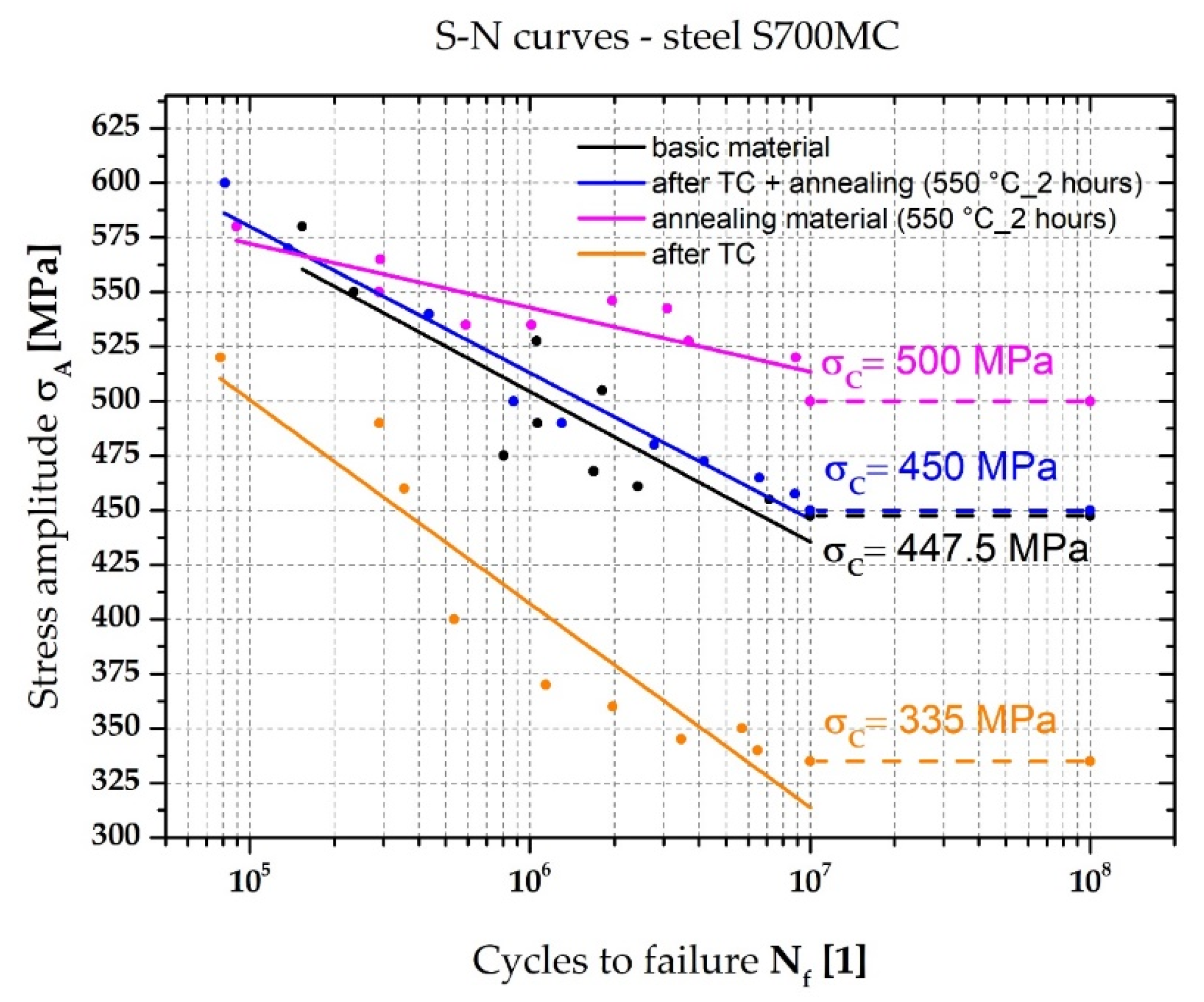
After annealing the S700MC steel samples (550 °C_2 h), the YS value remained unchanged but the UTS value decreased by 7.8%. At the same time, the fatigue strength increased by 10%, from 447.5 MPa to 500 Mpa;
(2)
Application of the temperature–stress cycle caused residual tensile stresses in the sample with a maximum value of 507 MPa and compressive residual stresses with a maximum value of 471 Mpa;
(3)
The application of the temperature–stress cycle also caused a decrease in the fatigue strength σc from 500 MPa to 335 MPa, i.e., a decrease of 33%;
(4)
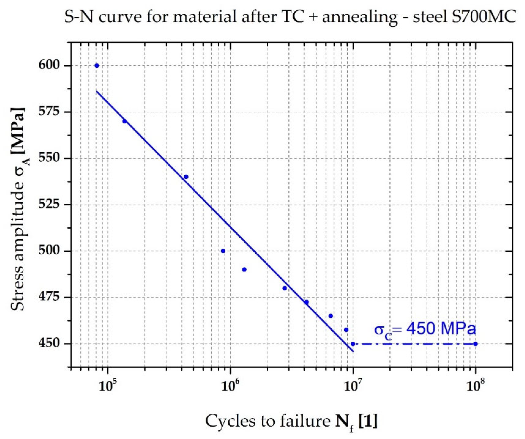
Annealing at 550 °C for 2 h caused the complete elimination of compressive residual stresses and a significant 80% reduction in tensile residual stresses in the samples subjected to the temperature–stress cycle. As a result, the fatigue strength of the samples increased from 335 MPa to 450 Mpa;
(5)
According to the above, residual stresses contribute to 69% of the fatigue strength reduction. The residue is due to material changes;
(6)
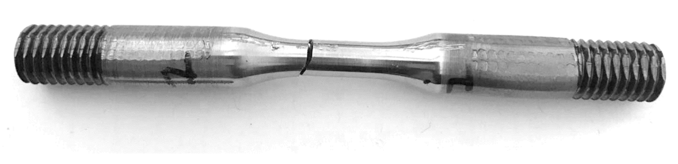
The samples with residual stresses fractured at a point 3.7 mm from the center of the sample, thus up to the tensile stress peaks. This is probably related to the redistribution of residual stresses that occur during cyclic loading.

Author Contributions

Conceptualization, Š.B. and J.M.; methodology, Š.B. and P.S.; software, Š.B. and P.S.; validation, J.M. and P.S.; formal analysis, Š.B.; investigation, Š.B. and P.S.; resources, Š.B. and J.M.; data curation, Š.B., P.S. and M.P.; writing—original draft preparation, Š.B.; writing—review and editing, J.M., P.S. and M.P.; visualization, Š.B. and P.S.; supervision, J.M.; project administration, Š.B.; funding acquisition, Š.B. All authors have read and agreed to the published version of the manuscript.

Funding

This research was funded by the Student Grant Competition of the Technical University of Liberec under the project No. SGS-2020-5008 “Influence of residual stresses during technological processing on fatigue life of manufactured parts”.

Data Availability Statement

Not applicable.

Conflicts of Interest

The authors declare no conflict of interest.

References

  1. De Meester, B. The Weldability of Modern Structural TMCP Steels. ISIJ Int. 1997, 37, 537–551. [Google Scholar] [CrossRef]
  2. Ufuah, E.; Ikhayere, J. Elevated Temperature Mechanical Properties of Butt-Welded Connections Made with High Strength Steel Grades S355 and S460M. In Design, Fabrication and Economy of Metal Structures; Springer: Berlin/Heidelberg, Germany, 2013; pp. 407–412. [Google Scholar]
  3. Lee, C.-H.; Shin, H.-S.; Park, K.-T. Evaluation of High Strength TMCP Steel Weld for Use in Cold Regions. J. Constr. Steel Res. 2012, 74, 134–139. [Google Scholar] [CrossRef]
  4. Zavdoveev, A.; Poznyakov, V.; Baudin, T.; Rogante, M.; Kim, H.S.; Heaton, M.; Demchenko, Y.; Zhukov, V.; Skoryk, M. Effect of Heat Treatment on the Mechanical Properties and Microstructure of HSLA Steels Processed by Various Technologies. Mater. Today Commun. 2021, 28, 102598. [Google Scholar] [CrossRef]
  5. Illescas Fernandez, S.; Fernández, J.; Asensio, J.; Sánchez Soto, M.; Guilemany Casadamon, J.M. Study of the Mechanical Properties of Low Carbon Content HSLA Steels. Rev. Metal. 2009, 45, 424–431. [Google Scholar] [CrossRef] [Green Version]
  6. Fernández, J.; Illescas, S.; Guilemany, J. Effect of Microalloying Elements on the Austenitic Grain Growth in a Low Carbon HSLA Steel. Mater. Lett. 2007, 61, 2389–2392. [Google Scholar] [CrossRef]
  7. Barbaro, F.; Kuzmikova, L.; Zhu, Z.; Li, H. Weld HAZ Properties in Modern High Strength Niobium Pipeline Steels. In Energy Materials 2014; Springer: Berlin/Heidelberg, Germany, 2014; pp. 657–664. [Google Scholar]
  8. Nazarov, A.; Yakushev, E.; Shabalov, I.; Morozov, Y.D.; Kireeva, T. Comparison of Weldability of High-Strength Pipe Steels Microalloyed with Niobium, Niobium and Vanadium. Metallurgist 2014, 57, 911–917. [Google Scholar] [CrossRef]
  9. Schaupp, T.; Schroepfer, D.; Kromm, A.; Kannengiesser, T. Welding Residual Stresses in 960 MPa Grade QT and TMCP High-Strength Steels. J. Manuf. Process. 2017, 27, 226–232. [Google Scholar] [CrossRef]
  10. Laitila, J.; Larkiola, J. Effect of Enhanced Cooling on Mechanical Properties of a Multipass Welded Martensitic Steel. Weld. World 2019, 63, 637–646. [Google Scholar] [CrossRef] [Green Version]
  11. Branco, R.; Berto, F. Mechanical Behavior of High-Strength, Low-Alloy Steels. Metals 2018, 8, 610. [Google Scholar] [CrossRef] [Green Version]
  12. Taavitsainen, J.; da Silva, P.S.V.; Porter, D.; Suikkanen, P. Weldability of Direct-Quenched Steel with a Yield Stress of 960 MPa. In Proceedings of the 10th International Conference on Trends in Welding Research and 9th International Welding Symposium of Japan Welding Society (9WS), Tokyo, Japan, 11–14 October 2016; Curran Associates, Inc.: Red Hook, NY, USA, 2017; pp. 11–14. [Google Scholar]
  13. Njock Bayock, F.; Kah, P.; Mvola, B.; Layus, P. Effect of Heat Input and Undermatched Filler Wire on the Microstructure and Mechanical Properties of Dissimilar S700MC/S960QC High-Strength Steels. Metals 2019, 9, 883. [Google Scholar] [CrossRef]
  14. Górka, J. Microstructure and Properties of the High-Temperature (HAZ) of Thermo-Mechanically Treated S700MC High-Yield-Strength Steel. Mater. Tehnol. 2016, 50, 617–621. [Google Scholar] [CrossRef]
  15. Moravec, J.; Novakova, I.; Sobotka, J.; Neumann, H. Determination of Grain Growth Kinetics and Assessment of Welding Effect on Properties of S700MC Steel in the HAZ of Welded Joints. Metals 2019, 9, 707. [Google Scholar] [CrossRef] [Green Version]
  16. Mičian, M.; Harmaniak, D.; Nový, F.; Winczek, J.; Moravec, J.; Trško, L. Effect of the T8/5 Cooling Time on the Properties of S960MC Steel in the HAZ of Welded Joints Evaluated by Thermal Physical Simulation. Metals 2020, 10, 229. [Google Scholar] [CrossRef] [Green Version]
  17. Jambor, M.; Ulewicz, R.; Nový, F.; Bokůvka, O.; Trško, L.; Mičian, M.; Harmaniak, D. Evolution of Microstructure in the Heat Affected Zone of S960MC GMAW Weld. Mater. Res. Proc. 2018, 5, 78–83. [Google Scholar]
  18. Kik, T. Computational Techniques in Numerical Simulations of Arc and Laser Welding Processes. Materials 2020, 13, 608. [Google Scholar] [CrossRef] [Green Version]
  19. Kik, T. Heat Source Models in Numerical Simulations of Laser Welding. Materials 2020, 13, 2653. [Google Scholar] [CrossRef]
  20. Nassiraei, H.; Rezadoost, P. Stress Concentration Factors in Tubular X-Connections Retrofitted with FRP under Compressive Load. Ocean Eng. 2021, 229, 108562. [Google Scholar] [CrossRef]
  21. Nassiraei, H.; Rezadoost, P. Stress Concentration Factors in Tubular T/Y-Connections Reinforced with FRP under in-Plane Bending Load. Mar. Struct. 2021, 76, 102871. [Google Scholar] [CrossRef]
  22. Nassiraei, H.; Rezadoost, P. SCFs in Tubular X-Connections Retrofitted with FRP under in-Plane Bending Load. Compos. Struct. 2021, 274, 114314. [Google Scholar] [CrossRef]
  23. Nassiraei, H.; Rezadoost, P. Parametric Study and Formula for SCFs of FRP-Strengthened CHS T/Y-Joints under out-of-Plane Bending Load. Ocean Eng. 2021, 221, 108313. [Google Scholar] [CrossRef]
  24. Lahtinen, T.; Vilaça, P.; Infante, V. Fatigue Behavior of MAG Welds of Thermo-Mechanically Processed 700MC Ultra High Strength Steel. Int. J. Fatigue 2019, 126, 62–71. [Google Scholar] [CrossRef]
  25. Kim, Y.; Hwang, W. Effect of Weld Seam Orientation and Welding Process on Fatigue Fracture Behaviors of HSLA Steel Weld Joints. Int. J. Fatigue 2020, 137, 105644. [Google Scholar] [CrossRef]
  26. Lago, J.; Trško, L.; Jambor, M.; Nový, F.; Bokůvka, O.; Mičian, M.; Pastorek, F. Fatigue Life Improvement of the High Strength Steel Welded Joints by Ultrasonic Impact Peening. Metals 2019, 9, 619. [Google Scholar] [CrossRef] [Green Version]
  27. Šebestová, H.; Hornik, P.; Mrňa, L.; Jambor, M.; Hornik, V.; Pokorný, P.; Hutař, P.; Ambrož, O.; Doležal, P. Fatigue Properties of Laser and Hybrid Laser-TIG Welds of Thermo-Mechanically Rolled Steels. Mater. Sci. Eng. A 2020, 772, 138780. [Google Scholar] [CrossRef]
  28. Moravec, J.; Sobotka, J.; Solfronk, P.; Thakral, R. Heat Input Influence on the Fatigue Life of Welds from Steel S460MC. Metals 2020, 10, 1288. [Google Scholar] [CrossRef]
  29. Hong, J.K.; Dong, P.; Brust, F.; Forte, T. Effect of Welding Induced Residual Stresses on the Fatigue Behavior of T-Joints; SAE Technical Paper: Warrendale, PA, USA, 1998. [Google Scholar]
  30. Webster, G.; Ezeilo, A. Residual Stress Distributions and Their Influence on Fatigue Lifetimes. Int. J. Fatigue 2001, 23, 375–383. [Google Scholar] [CrossRef]
  31. James, M.; Hughes, D.; Chen, Z.; Lombard, H.; Hattingh, D.; Asquith, D.; Yates, J.; Webster, P. Residual Stresses and Fatigue Performance. Eng. Fail. Anal. 2007, 14, 384–395. [Google Scholar] [CrossRef] [Green Version]
  32. Lee, C.-H.; Chang, K.-H. Comparative Study on Girth Weld-Induced Residual Stresses between Austenitic and Duplex Stainless Steel Pipe Welds. Appl. Therm. Eng. 2014, 63, 140–150. [Google Scholar] [CrossRef]
  33. Harati, E.; Karlsson, L.; Svensson, L.-E.; Dalaei, K. The Relative Effects of Residual Stresses and Weld Toe Geometry on Fatigue Life of Weldments. Int. J. Fatigue 2015, 77, 160–165. [Google Scholar] [CrossRef]
  34. Kang, H.T.; Lee, Y.-L.; Sun, X.J. Effects of Residual Stress and Heat Treatment on Fatigue Strength of Weldments. Mater. Sci. Eng. A 2008, 497, 37–43. [Google Scholar] [CrossRef]
  35. Jandera, M.; Machacek, J. Residual Stresses and Strength of Hollow Stainless Steel Sections. 2007, pp. 262–263. Available online: https://www.researchgate.net/profile/Michal-Jandera/publication/268358021_RESIDUAL_STRESSES_AND_STRENGTH_OF_HOLLOW_STAINLESS_STEEL_SECTIONS/links/54b78e070cf2bd04be33a1f3/RESIDUAL-STRESSES-AND-STRENGTH-OF-HOLLOW-STAINLESS-STEEL-SECTIONS.pdf (accessed on 2 November 2022).
  36. Dakhlaoui, R.; Braham, C.; Baczmański, A. Mechanical Properties of Phases in Austeno-Ferritic Duplex Stainless Steel—Surface Stresses Studied by X-Ray Diffraction. Mater. Sci. Eng. A 2007, 444, 6–17. [Google Scholar] [CrossRef]
  37. Johansson, J.; Odén, M. Load Sharing between Austenite and Ferrite in a Duplex Stainless Steel during Cyclic Loading. Metall. Mater. Trans. A 2000, 31, 1557–1570. [Google Scholar] [CrossRef]
  38. Jang, D.; Watkins, T.; Kozaczek, K.; Hubbard, C.; Cavin, O. Surface Residual Stresses in Machined Austenitic Stainless Steel. Wear 1996, 194, 168–173. [Google Scholar] [CrossRef]
  39. Ragavendran, M.; Vasudevan, M.; Hussain, N. Study of the Microstructure, Mechanical Properties, Residual Stresses, and Distortion in Type 316LN Stainless Steel Medium Thickness Plate Weld Joints. J. Mater. Eng. Perform. 2022, 31, 5013–5025. [Google Scholar] [CrossRef]
  40. ČSN EN 10027-1; Systémy Označování Ocelí–Část 1: Stavba Značek Ocelí. Praha: Úřad pro Technickou Normalizaci, Metrologii a Státní Zkušebnictví, 2017; 40 s. Třídící Znak 42 0011.
  41. ČSN EN 10027-2; Systémy Označování Ocelí–Část 2: Systém Číselného Označování. Praha: Úřad pro Technickou Normalizaci, Metrologii a Státní Zkušebnictví, 2016; 24 s. Třídící Znak 42 0011.
  42. Moravec, J.; Sobotka, J.; Novakova, I.; Bukovska, S. Assessment the Partial Welding Influences on Fatigue Life of S700MC Steel Fillet Welds. Metals 2021, 11, 334. [Google Scholar] [CrossRef]
Figure 1. Tested material S700MC—ferritic-bainitic structure.
Metals 12 01890 g001
Figure 2. Drawing of the sample for simulations in Gleeble (in mm) [34].
Metals 12 01890 g002
Figure 3. Sample drawing for fatigue testing acc. to standard EN 3987 (in mm) [35].
Metals 12 01890 g003
Figure 4. Temperature cycle used for physical simulations (1365 °C).
Metals 12 01890 g004
Figure 5. Residual stresses after machining (black curve) and after annealing (red curve).
Metals 12 01890 g005
Figure 6. The final S–N curve of the base and annealed materials of S700MC steel.
Metals 12 01890 g006
Figure 7. Sample in the device Gleeble 3500.
Metals 12 01890 g007
Figure 8. Detail of grain growth in the HAZ of S700MC steel.
Metals 12 01890 g008
Figure 9. Courses of residual stresses after application of temperature cycles, for sample 1 (red curve), for sample 2 (blue curve), for sample 3 (grey curve).
Metals 12 01890 g009
Figure 10. Courses of residual stresses after application of temperature cycles (red curve) and after annealing to reduce residual stresses (blue curve).
Metals 12 01890 g010
Figure 11. S–N curve of samples with residual stress.
Metals 12 01890 g011
Figure 12. S–N curve of samples with residual stress and subsequent annealing at 550 °C for 2 h.
Metals 12 01890 g012
Figure 13. Comparison of all measured S–N curves, base material (black curve), annealed material at 550 °C for 2 h (pink curve), after TC (orange curve), after TC + HT 550 °C for 2 h (blue curve).
Metals 12 01890 g013
Figure 14. Sample after fatigue test.
Metals 12 01890 g014
Table 1. Chemical composition (wt. %) of the S700MC steels.
CSiMnPSAlNbV
ČSN EN 10149-2max. 0.12max. 0.6max. 2.2max. 0.025max. 0.010min. 0.015max. 0.09max. 0.2
Experiment0.0500.1961.9140.0060.0060.0370.0630.072
TiMoBNNiCrW
ČSN EN 10149-2max. 0.25max. -max. 0.005----
Experiment0.0560.11200.0130.1530.0350.035
Table 2. Mechanical properties of tested material S700MC.
Sample
No.
YS [MPa]UTS [MPa]Ag [%]A30 [%]
Basic material748 ± 9851 ± 111.08 ± 0.6224.03 ± 0.62
Annealing material (550 °C_2 h)745 ± 3785 ± 39.69 ± 0.1221.16 ± 0.29
Table 3. Fatigue test results for base material S700MC and annealed materials.
Basic materialσA [MPa]580550527.5505490
Nf [1]153,695234,9421,056,3761,804,8941,063,721
σA [MPa]475468461455447.5
Nf [1]804,5131,687,4522,420,8227,153,698107
550 °C 2 hσA [MPa]580565550546542.5
Nf [1]89,479292,247288,8981,964,3213,083,698
σA [MPa]535535527,5520500
Nf [1]589,1381,011,5743,680,7778,881,583107
Table 4. Results of fatigue tests of samples with residual stress.
After TCσA [MPa]520490460400370
Nf [1]78,412290,364354,888536,2421,138,628
σA [MPa]360350345340335
Nf [1]1,968,3485,698,1763,458,2656,483,620107
Table 5. Results of fatigue tests of samples after TC and annealing 550 °C for 2 h.
After TC + annealingσA [MPa]600570540500490
Nf [1]81,275136,846436,195874,6931,297,314
σA [MPa]480472.5465457.5450
Nf [1]2,769,6744,181,2396,583,9128,826,743107
Publisher’s Note: MDPI stays neutral with regard to jurisdictional claims in published maps and institutional affiliations.

