Abstract
The mixed structure of lath bainite and martensite was obtained by isothermal transformation tests at 698 K, 673 K and 623 K in ultra-high-strength steel. The interweaving mode of lath bainite and martensite was revealed by colored metallography and band contrast maps based on Gaussian fit. The crystallographic characteristics were analyzed in terms of variant pairing. The twin-related V1/V2 variant pairs were found in the region with high band contrast (BC) values, inferred as lath bainite. While in the low-BC value region, which was inferred as lath martensite, besides the dominated twin-related V1/V2 variant pair, V1/V4 variant pairs with low-angle grain boundaries were occasionally revealed. According to the classification by Takayama et al., both variant pairings of lath bainite and martensite in this work correspond to a type II mode. The present work has confirmed, even with complex microstructure, i.e., mixed lath bainite and martensite were formed depending on the processing route, bainite and martensite still follow their own rules of variant pairing.
1. Introduction
Bainite and martensite are indispensable constituent phases in ultra-high-strength structural steels [1,2]. Bainitic or martensitic laths in general hold a Kurdjumov–Sachs orientation relationship (K–S OR) [3,4,5,6] with respect to their parent austenite grain ((111)γ//(011)α, [-101]γ//[-1-11]α). As shown in Table 1, there are 24 orientations (denoted as variants) within a single austenite grain in the KS OR. These 24 variants can be separated into four close-packed (CP) groups, each of which consists of six variants sharing the same parallel relationship of close-packed planes with the austenite or grouped according to three distinctive variants of Bain correspondence, i.e., Bain groups. The hierarchic structural units, i.e., packets and blocks are defined from the perspective of variant grouping, where a packet corresponds to the aggregate of variants coming from the same CP group, and a block consists of variants from both the same CP and Bain groups. The boundaries separating packets and blocks are mostly high-angle grain boundaries with a misorientation angle of ≥15°. Therefore, variant selection of bainite or martensite plays a decisive role in determining the density of HAGBs.

Table 1.
The 24 crystallographic variants in K–S OR [5,6].
Morito et al. [7] revealed the characteristic feature of lath martensite in Fe-<0.01C-3.14Mn IF steel and Fe-18Ni-8Co-5Mo maraging steel. Six possible variants form in a packet while the block is made up of subblocks V1 and V4 with low misorientation. When higher carbon content, e.g., 0.61 or 0.75 wt.%, is added in series of Fe-C alloys [8,9], each block consists of laths with a single variant, resulting in a higher density of HAGBs. Compared to lath martensite, the crystallography of lath bainite has been investigated in more detail. For bainite transformation at 723 K in Fe-9Ni-0.15C alloy, Furuhara et al. [10] reported that the activation energy was decisive for variant selection at the beginning of the transformation; while later, the plastic accommodation of shape strain came into effect to a larger extent. Miyamoto et al. [11] proposed a preferential nucleation model for variant selection of lath bainite from deformed austenite, where activation energy also played a key role. Kaneshita et al. [12] examined the bainite transformation in Fe-2Mn-C with a carbon content of 0.2–0.75 wt. % and found that, at a higher carbon content and transformation temperature of 673 K, the shape strain was accommodated mainly by austenite grain boundary sliding, encouraging the self-accommodation and thus the multiplication of variants. Furuhara et al. [5] and Takayama et al. [6] studied isothermal bainite transformation in Fe-9Ni-C alloys and Fe-0.15C-1.5Mn-0.2Si steel, respectively. Both of them reported the coarse bainitic packet formed at a high temperature consisted of two specific variants with a low-angle grain boundaries (LAGBs, 5–15°), and each favorable twin-related variant pair constituted a block at low temperature.
Most of the above investigations were conducted with model alloys, aiming at the understanding of variant pairing mechanisms in either bainite or martensite. Recently, Wang and Shang et al. [13,14,15,16] analyzed the variant pairing in a heat-affected zone of high-strength, low-alloy steels and related it with toughness. To further study the variant pairing in engineering materials, ultra-high-strength steel was employed in this work where, in contrast to most of the previously reported research, a mixed structure of lath bainite and martensite was present. Using band contrast maps, lath bainite and martensite were differentiated and variant pairings were identified.
2. Materials and Methods
The nominal composition of the experimental steel targeted for manufacturing ultra-high-strength mooring chain [17] is shown in Table 2. The bainite (Bs) and martensite (Ms) start temperatures were respectively determined to be 753 K and 643 K by a computer program “mucg83.f (University of Cambridge, Cambridge, the United Kingdom)” [18]. Mixed bainite and martensite can be expected for the isothermal tests below Bs.
Table 2.
The chemical composition of experimental steel (weight percent).
Isothermal tests were conducted on a Formaster FII (Fuji Electric, Tokyo, Japan) dilatometer. Cylinder samples with a diameter of 3 mm and a height of 10 mm were first austenitized at 1473 K for 180 s and then rapidly cooled at a rate of 40 K/s to 698 K, 673 K and 623 K for isothermal transformation with the period of 4800 s, respectively (referred as IT698, IT673 and IT623 for convenience). Gas-quenching was finally applied to enable the transformation of retained austenite to martensite. Herein, the cooling rate of 40 K/s was employed to avoid high-temperature transformation products prior to isothermal transformation, and the holding time of 4800 s was to ensure the stasis of bainite transformation at different temperatures.
Samples for microstructural characterization were prepared by grinding, polishing and etching in 4% Nital solution. The colored metallography was also obtained by the tint-etching method, with a solution of 1% aqueous solution of sodium metabisulfite and 4% picric acid in ethyl alcohol in a 1:1 ratio [19,20,21]. Microstructural features were captured by ZEISS ULTRA 55 (Carl Zeiss AG, Oberkochen, Germany). The electron backscattered diffraction (EBSD) samples were electro-polished in a solution consisting of 10% perchloric acid and 90% absolute ethyl alcohol at room temperature and a potential of 20 V for 20 s. EBSD data was obtained with an acceleration voltage of 20 kV, a working distance of 15 mm, a tilt angle of 70° and a step size of 0.15 μm. Channel 5 HKL software (Oxford Instruments, Hobro, Denmark) was employed to post-process the EBSD data.
3. Results and Discussions
3.1. Morphological Characterization
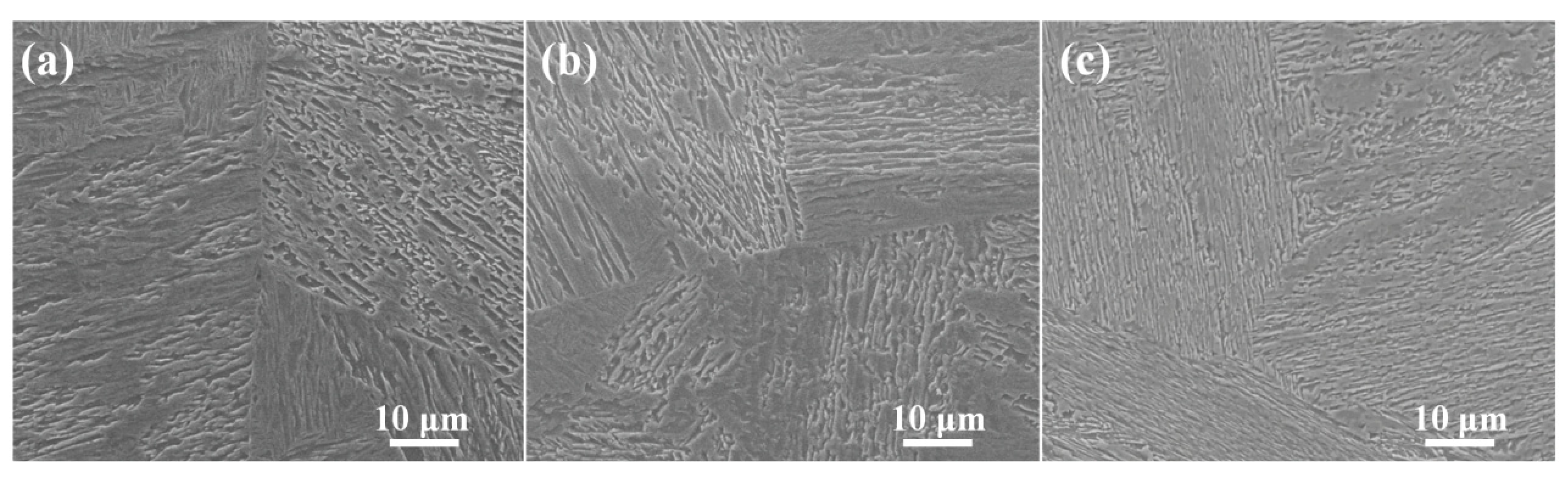
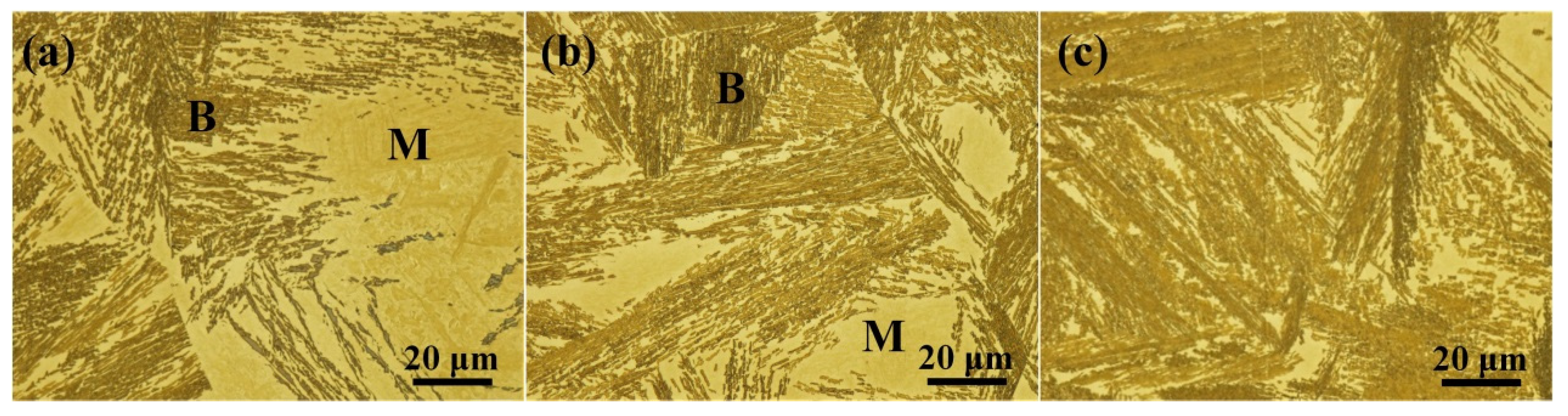
Figure 1 shows the morphology of isothermally transformed samples which are characterized by a mixed structure of lath bainite and martensite. Due to the difference in electrochemical properties, the bainitic or martensitic substructures with different crystallographic orientations, i.e., packets can be differentiated by their gray level. It should be pointed out that, in contrast to the isolated bainite or martensite analyzed in previous works [4,5,6,7,8,9], most of the scanned region in this work exhibits a characteristic interweaving mode of lath bainite and martensite. This was further confirmed by the colored metallographic images in Figure 2, where the brownish and yellowish region corresponds to bainite and martensite respectively. This characteristic microstructure is similar to that reported by Bhadeshia et al. [22], where bainite formed subsequently to the martensite transformation, filling the vacant spaces between martensitic blocks. In addition, as shown in Figure 2, the large isolated martensite region formed in IT698 and IT673.
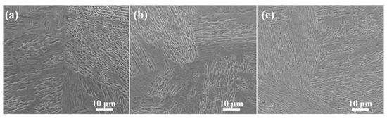
Figure 1.
SEM micrographs of (a) IT698, (b) IT673 and (c) IT623.
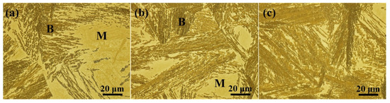
Figure 2.
Colored metallography of (a) IT698, (b) IT673 and (c) IT623. (B: bainite, M: martensite.).
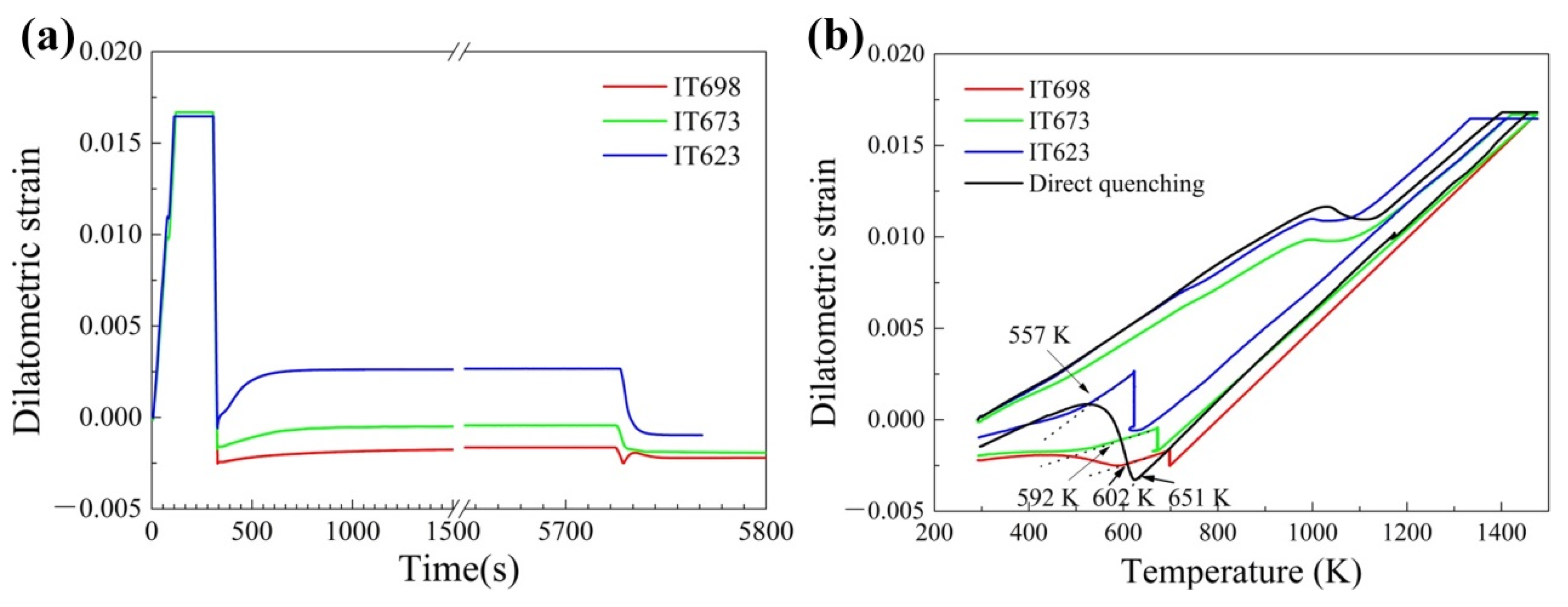
The presence of a large fraction of martensite corresponds well with the dilatation curves in Figure 3. The dilatation starts at the beginning of isothermal holding and levels off before the end of isothermal holding (see Figure 1a), reflecting the whole bainite transformation process. Retained austenite finally transforms into martensite during the gas-quenching. From Figure 3b, the bainite fraction is measured by lever rule [23,24] and the Ms temperature for IT698, IT673 and IT623 are determined to be 42% and 602 K, 53% and 592 K, 72% and 557 K, respectively. Retained austenite is not detected by EBSD.
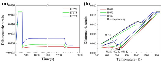
Figure 3.
Dilatometric strain as a function of (a) time and (b) temperature. The arrow indicates the start temperature of martensite transformation during the final gas-quenching.
3.2. Mixed Lath Bainite and Martensite
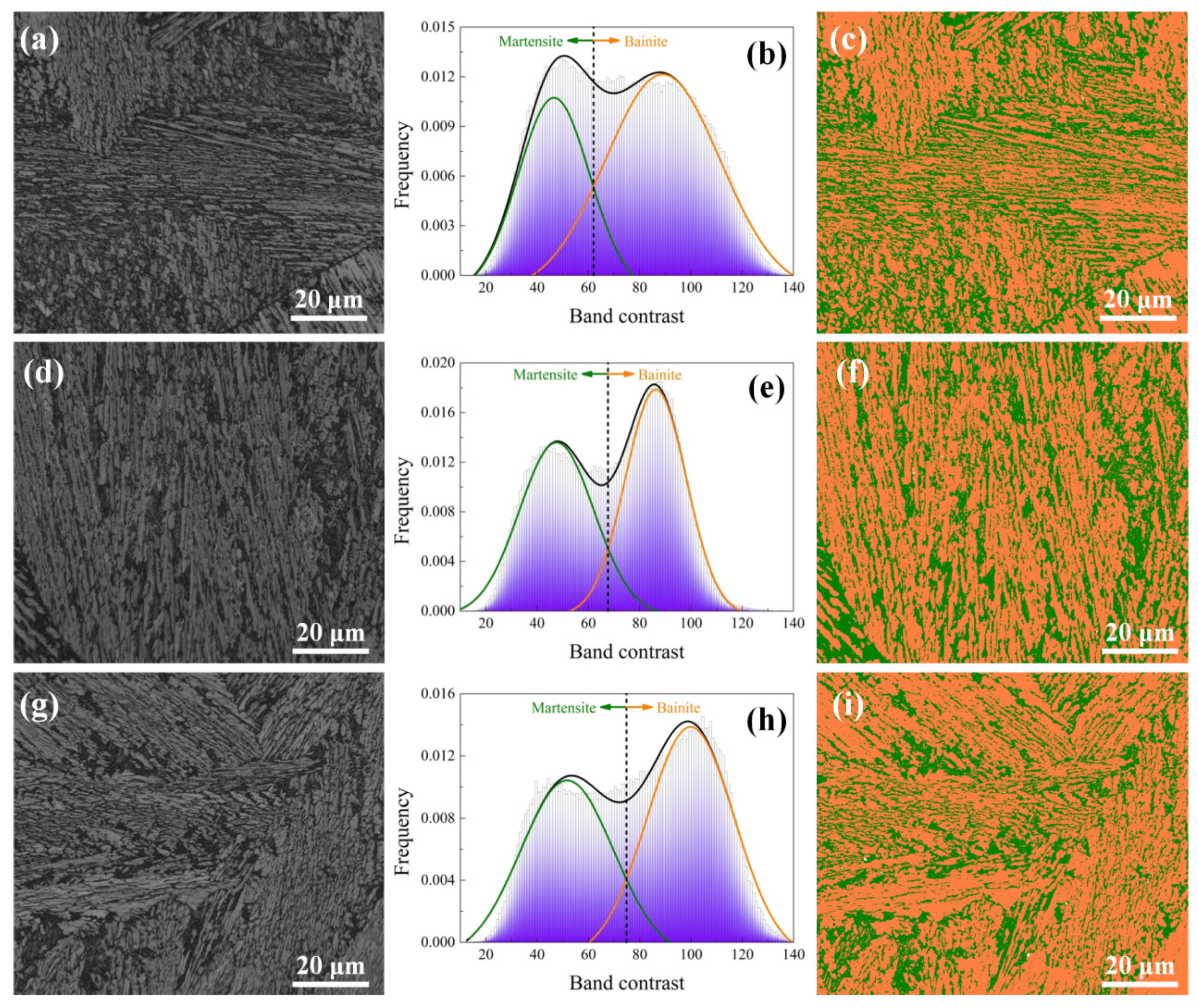
The band contrast (BC) maps are illustrated in Figure 4a,d,g, where the BC value directly relies on the quality of Kikuchi patterns and a higher BC value indicates a higher intensity of Kikuchi pattern. Martensite, in general, contains greater lattice imperfection than bainite, leading to its lower intensity of Kikuchi pattern and thus BC value [25,26,27]. Therefore, BC value has already been used as a critical indicator for differentiating bainite and martensite. In Da Silva et al.’s work [28], BC values were fitted with two peaks assuming a Gaussian distribution to distinguish tempered martensite from lower bainite. Y. Wang et al. [26] and Baek et al. [27] also conducted a quantitative analysis of the martensite and bainite fraction using BC values through Gaussian fit. In the present study, the BC reference point for differentiating bainite and martensite is located by Gaussian fit as presented in Figure 4b,e,h and defined as the intersection point of the two peaks from bainite and martensite [26,27,28]. The filtered results are shown in Figure 4c,f,i, where bainite and martensite are colored orange and olive, respectively. The highly mixed microstructure can be noticed. In addition, it should be mentioned that the large, isolated martensite region in Figure 1 is not present in Figure 4 due to the selected observation region.
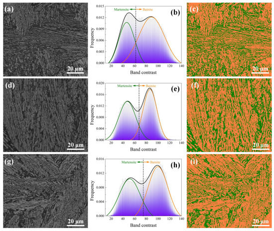
Figure 4.
(a,d,g) BC maps, (b,e,f) the distribution of BC values and Gaussian fit and (c,f,i) BC maps based on the Gaussian fit of (a–c) IT698, (b–f) IT673 and (g–i) IT623 (Martensite and bainite in (c,f,i) are colored in olive and orange, respectively.).
Figure 5a–c displays grain boundary maps by the categories of LAGBs (5–15°), Σ3 boundaries and other HAGBs (≥15°, except Σ3 boundaries); they are colored the red, blue, and green lines, respectively. The fraction of LAGBs is relatively low and most of the parallel lath bundles boundaries are Σ3 twin-related boundaries. Using the BC maps in Figure 4a,d,g and the GB maps in Figure 5a–c, one can observe the boundaries between different aggregates of parallel lath in the IT698 LAGBs and other LAGBs in three samples mostly located in the martensite region. The distribution of grain boundary misorientation was plotted in Figure 5d. A large fraction of boundaries misorientated by 2–5° can be noticed. They correspond to the boundaries between lathes of the same variant. In addition, the frequency of Σ3 boundaries and other HAGBs is much higher than that of LAGBs.
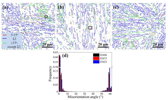
Figure 5.
(a–c) GB maps and (d) the distribution of boundary misorientation angle of (a) IT698, (b) IT673 and (c) IT623. The regions selected by black squares will be analyzed in detail below.
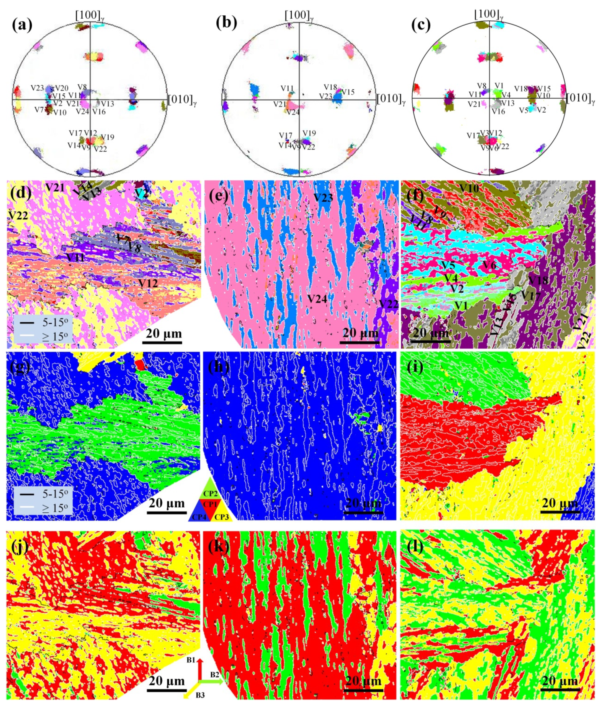
The region belonging to a prior austenite grain was extracted using the (001)γ stereographic projection on which <001>α with a K–S OR to austenite were plotted. Compared with the standard (001)γ stereographic projection [4], the individual variant can be identified. The IPF maps, corresponding (001)γ pole figure, CP map and Bain maps are illustrated in Figure 6.

Figure 6.
(a–c) the (001)γ stereographic projection on which <001>α directions with a K–S OR to γ in single prior austenite grain, (d–f) variant identification and IPF maps colored according to (g–i) CP group and (j–l) Bain group: (a,d,g,j) IT698, (b,e,h,k) IT673 and (c,f,i,l) IT623. (V1: variant 1; …V24: variant 24. B1: Bain 1; …B3: Bain 3.)
According to the (001)γ pole figure in Figure 6a–c, variants were identified in Figure 6d–f. They were colored according to CP groups in Figure 6g–i and Bain groups in Figure 6j–l, respectively. In Figure 6d–f, several variants misorientated by HAGBs colored in white are formed as well as the variants misorientated by LAGBs within a region surrounded by HAGB. In IT698, all six variants from V7 to V12 belonging to CP2 appear in the martensite region (see Figure 4c), the remaining area of the prior austenite grain is the bainite region occupied by V21 and V22, which belong to CP4. In IT673, the majority of the analyzed prior austenite grain has transformed into bainite of V23 and V24. Occasionally, the appearance of variant pairs V21/V24 and V19/V22 can be observed, especially on the right region inferred as martensite. In IT623, a highly complex microstructure with several aggregates of parallel lath impinging at the center region (Figure 6f) was captured. Generally speaking, all four close-packed groups, i.e., CP1(V1 to V6), CP2(V7 to V12), CP3(V13 to V18) and CP4(V19 to V24), were identified. From Figure 6g–l, it was clearly shown that variants sharing the same CP parallel relation were formed side-by-side, indicating the CP grouping mode and the development of ordinary packet structures for all three samples. When comparing the CP and Bain map for each of the three samples, it is found that each CP region consists of two or three Bain groups.
Using Figure 6, one can identify the boundaries with different misorientation angles in Figure 5a–c for their specific type, i.e., packet boundaries, block boundaries and subblock boundaries and the corresponding variant pairs. Specifically, red lines representing LAGBs correspond to type V1/V4 subblock boundaries or type V1/V8, V1/V11, V1/V13 packet boundaries. Blue lines, which indicate Σ3 twin-related boundaries, correspond to type V1/V2 block boundaries. Green lines representing other HAGBs, correspond to type V1/V3, V1/V5, V1/V6 block boundaries; packet boundaries between all other variants and V1; and prior austenite grain boundaries. The types of inter-variant boundaries with respect to V1 are listed in Table 1. It should be mentioned that, within every packet, any variant can be designated as V1 for variant identification and thus equivalent variant pairs exist.
According to Figure 5 and Figure 6, it is found that HAGBs, especially the Σ3 boundaries (V1/V2 twin-related boundaries), dominate every packet in all three samples. The majority of red lines i.e., LAGBs in Figure 5a are packet boundaries between CP3 and CP4, CP2 and CP4. In contrast, the packet boundaries in Figure 6i all belong to the category of other HAGBs. The other red lines in Figure 5a–c located as described previously, mostly in the martensite region, are the type V1/V4 subblock boundaries. The two boxed regions in Figure 5a,b are analyzed in detail in Figure 7, where LAGBs, Σ3 boundaries and other HAGBs are delineated in red, blue and green lines, respectively. The selected regions for both IT698 and IT673 correspond to the martensite region. It is seen from Figure 7a that B1 (block 1) has a single variant, while B2 (block 2) is made up of subblocks V7 and V10. The point-to-point misorientation profile in Figure 7c shows that the inter-variant boundaries within a block are LAGBs, i.e., V7/V10 subblock boundaries with a misorientation angle of around 5°. As reported by Morito et al. [7], there are no long-range accumulative misorientations within each block and the misorientation angle of type V1/V4 subblock boundaries is slightly higher than 5°, which agrees well with the results in Figure 7c. In Figure 7d–f, in addition to the similar results in Figure 7a–c, the block boundaries include both the Σ3 twin-related boundaries and other HAGBs.
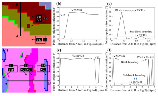
Figure 7.
Variant pairing of the selected regions from GB maps, the point-to-origin misorientation and the point-to-point misorientation profile from A to B: (a–c) IT698 and (d–f) IT673. Grain boundaries are colored in: red, LAGBs; blue, Σ3 boundaries; green, other HAGBs. Black arrows indicate variants and blue arrows indicate the types of boundary. (V1: variant 1, … V24: variant 24. B1: block 1; …B3: block 3.)
3.3. Isolated Martensite
Analysis of the isolated martensite region from a prior austenite grain was carried out in IT698 and IT673 and the results are shown in Figure 8. According to the BC maps based on Gaussian fit in Figure 8c,d, the triangular region of isolated martensite can be identified in IT698, while the scanned region is almost completely occupied by martensite in IT673. Following the variant identification method in Figure 6, most blocks contain a single variant, and type V1/V2 twin-related variants develop adjacently. A type V1/V4 variant pair within a block has been revealed in some martensite areas in Figure 8e,f, i.e., V1/V4, V14/V17 and V15/V18 in IT698 and V2/V5 in IT673. Nevertheless, the majority of each packet in the martensite region is dominated by a type V1/V2 variant pair as represented by the large fraction of Σ3 boundaries in Figure 8a,b.
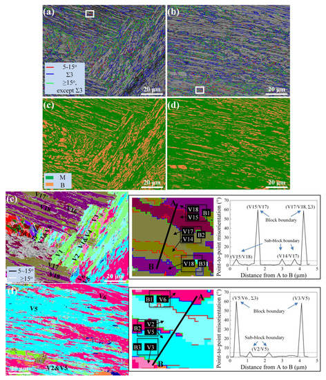
Figure 8.
(a,b) GB and BC maps, (c,d) BC maps based on the Gaussian fit and (e,f) variant pairing: (a,c,e) IT698 and (b,d,f). The insets show the variant pairing of the selected region in (e,f) and the corresponding point-to-point misorientation profile from A to B. Black arrows indicate variants and blue arrows indicate the types of boundary. (V1: variant 1; …V24: variant 24. B1: block 1; …B3: block 3.)
3.4. The Relationship between Variant Pairing and Chemical Driving Force
Variant pairing can be classified into three types [5,6]: type I—packets consisting of variants from the same Bain group; type II—ordinary packets in which variants belonging to the same CP group are formed, while in particular, the twin-related V1/V2 pair is dominant; type III—variants in the same CP group are formed adjacently, but the V1/V4 pairing with a low misorientation angle is preferred. Takayama et al.’s work [6], reported that bainite transformation was dominated by type I or type II variant pairing. In the present study, type II variant pairing is predominant in the mixed structure of lath bainite and martensite; type III variant pairing occasionally occurred in the martensite region.
It was found [5,6] that variant pairing was principally affected by chemical driving force and transformation temperature, and their relationship could be summarized by Figure 9. The data from the present study was obtained from the scanned region of 228 × 172 μm2 for IT698, 228 × 172 μm2 for IT673 and 258 × 114 μm2 for IT623 (a smaller total area due to the absence of large, isolated martensite). The data published in Takayama et al.’s work [6] were also included to expand the database. The chemical driving force was calculated by Thermo-Calc Classic, Version S (Thermo-Calc Software AB, Stockholm, Sweden) with the TCFE9 database. The start temperature of the martensite transformation [29] was related to the carbon content, so the transformation temperature range for bainite and martensite probably overlaps in different steels. Therefore, the bainite and martensite transformations are considered separately. The magenta stars in Figure 9a from the present work have enlarged the region of type II variant pairing for bainite transformation. The upper blue and lower magenta stars in Figure 9b represent martensite in this work with dominant type II and occasional type III variant pairing.
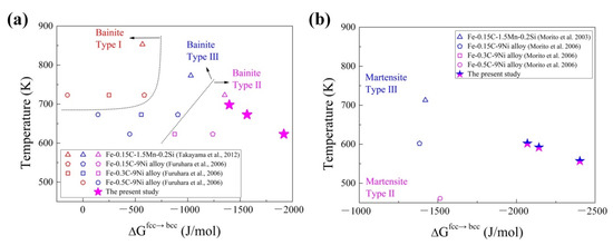
Figure 9.
Effect of the driving forces for (a) bainite and (b) martensite transformation on the crystallographic characteristics. [5,6,7,8] The marks representing variant pairing type are colored as follows: red, type I; magenta, type II; blue, type III; upper blue and lower magenta, type II dominated with occasional type III.
For bainite transformation with a low chemical driving force and high transformation temperature, i.e., the left-upper corner of Figure 9a, the effect of boundary energy relative to the driving force on nucleation of bainitic ferrite is larger. A specific variant is selected by the nature of an austenite boundary, and the neighboring austenite matrix plastically accommodates the shear strain from bainitic lath formation. In the opposite case of a larger driving force and lower transformation temperature, a difference in activation energy between different variant pairs becomes smaller, and minimization of shear strain by self-accommodation due to the strengthening of austenite dominates the variant pairing. The transformation temperature and chemical driving force act in a similar way on the selection of the variant pairing mode for martensite transformation. However, the boundary between type II and type III variant pairings for martensite is unable to be revealed in Figure 9b due to limited data.
Even though complex microstructures of lath bainite and martensite form depending on the processing route, the present work has confirmed bainite and martensite still follow their own rules of variant pairing as suggested in Figure 9. This adds another dimension to the design of alloy composition and processing, since variant pairing directly determines the density of HAGBs. According to the Figure 9b and the measured Ms temperature, i.e., 651 K in Figure 3b, direct quenching would probably produce martensite with type III variant pairing, while isothermal holding at lower temperature, e.g., 623 K and 673 K, led to the formation of a bainitic matrix with type II variant pairing and embedded martensite with the dominated type II variant pairing. Further studies are required to establish the linkage between mechanical properties and variant pairing.
4. Conclusions
The morphologic and crystallographic characteristics of the mixed structure of lath bainite and martensite in ultra-high-strength steel were characterized. In both lath bainite and martensite, a single variant constitutes a block, and twin-related variant pairs form in a packet, creating the highest frequency of HAGBs and validating the type II variant pairing as classified by Takayama et al. Blocks containing subblocks with low-misorientated variants pairs, corresponding to type III variant pairing, were occasionally found in lath martensite. The variant pairing can be rationalized from the perspective of driving force and temperature.
Author Contributions
Conceptualization, M.L. and T.J.; methodology, T.J.; software, M.L. and T.J.; validation, M.L. and T.J.; formal analysis, M.L.; investigation, M.L. and S.W.; resources, X.Z.; data curation, M.L. and S.W.; writing—original draft preparation, M.L.; writing—review and editing, T.J.; visualization, M.L.; supervision, T.J.; project administration, X.Z.; funding acquisition, T.J. All authors have read and agreed to the published version of the manuscript.
Funding
This research was funded by the National Key R & D Program of China (2017YFB0304201) and the Fundamental Research Funds for the Central Universities (N180702012). The APC was funded by [2017YFB0304201].
Institutional Review Board Statement
Not applicable.
Informed Consent Statement
Not applicable.
Data Availability Statement
Not applicable.
Conflicts of Interest
The authors declare no conflict of interest.
References
- Jia, T.; Zhou, Y.; Jia, X.; Wang, Z. Effects of Microstructure on CVN Impact Toughness in Thermomechanically Processed High Strength Microalloyed Steel. Met. Mater. Trans. A 2017, 48, 685–696. [Google Scholar] [CrossRef]
- Zhao, H.; Palmiere, E.J. Influence of cooling rate on the grain-refining effect of austenite deformation in a HSLA steel. Mater. Charact. 2019, 158, 109990. [Google Scholar] [CrossRef]
- Kurdjumow, G.; Sachs, G. Der Mechanismus der Stahlhärtung. Naturwissenschaften 1930, 18, 534. [Google Scholar] [CrossRef]
- Kitahara, H.; Ueji, R.; Tsuji, N.; Minamino, Y. Crystallographic features of lath martensite in low-carbon steel. Acta Mater. 2006, 54, 1279–1288. [Google Scholar] [CrossRef]
- Furuhara, T.; Kawata, H.; Morito, S.; Maki, T. Crystallography of upper bainite in Fe–Ni–C alloys. Mater. Sci. Eng. A 2006, 431, 228–236. [Google Scholar] [CrossRef]
- Takayama, N.; Miyamoto, G.; Furuhara, T. Effects of transformation temperature on variant pairing of bainitic ferrite in low carbon steel. Acta Mater. 2012, 60, 2387–2396. [Google Scholar] [CrossRef]
- Morito, S.; Huang, X.; Furuhara, T.; Maki, T.; Hansen, N. The morphology and crystallography of lath martensite in alloy steels. Acta Mater. 2006, 54, 5323–5331. [Google Scholar] [CrossRef]
- Morito, S.; Tanaka, H.; Konishi, R.; Furuhara, T.; Maki, T. The morphology and crystallography of lath martensite in Fe-C alloys. Acta Mater. 2003, 51, 1789–1799. [Google Scholar] [CrossRef]
- Stormvinter, A.; Miyamoto, G.; Furuhara, T.; Hedström, P.; Borgenstam, A. Effect of carbon content on variant pairing of martensite in Fe–C alloys. Acta Mater. 2012, 60, 7265–7274. [Google Scholar] [CrossRef]
- Furuhara, T.; Kawata, H.; Morito, S.; Miyamoto, G.; Maki, T. Variant Selection in Grain Boundary Nucleation of Upper Bainite. Met. Mater. Trans. A 2008, 39, 1003–1013. [Google Scholar] [CrossRef]
- Miyamoto, G.; Iwata, N.; Takayama, N.; Furuhara, T. Variant selection of lath martensite and bainite transformation in low carbon steel by ausforming. J. Alloy. Compd. 2013, 577, S528–S532. [Google Scholar] [CrossRef]
- Kaneshita, T.; Miyamoto, G.; Furuhara, T. Variant selection in grain boundary nucleation of bainite in Fe-2Mn-C alloys. Acta Mater. 2017, 127, 368–378. [Google Scholar] [CrossRef]
- Wang, X.L.; Wang, Z.Q.; Ma, X.P.; Subramanian, S.V.; Xie, Z.J.; Shang, C.J.; Li, X.C. Analysis of impact toughness scatter in simulated coarse-grained HAZ of E550 grade offshore engineering steel from the aspect of crystallographic structure. Mater. Charact. 2018, 140, 312–319. [Google Scholar] [CrossRef]
- Wang, X.L.; Wang, Z.Q.; Xie, Z.J.; Wang, J.L.; Li, X.C.; Shang, C.J. Toughening coarse grained heat affected zone of high strength offshore engineering steel by enhancing the completeness of austenite-bainite transformation. Mater. Lett. 2019, 257, 126727. [Google Scholar] [CrossRef]
- Wang, X.L.; Ma, X.P.; Wang, Z.Q.; Subramanian, S.V.; Xie, Z.J.; Shang, C.J.; Li, X.C. Carbon microalloying effect of base material on variant selection in coarse grained heat affected zone of X80 pipeline steel. Mater. Charact. 2019, 149, 26–33. [Google Scholar] [CrossRef]
- Wang, X.L.; Wang, Z.Q.; Dong, L.L.; Shang, C.J.; Ma, X.P.; Subramanian, S.V. New insights into the mechanism of cooling rate on the impact toughness of coarse grained heat affected zone from the aspect of variant selection. Mater. Sci. Eng. A 2017, 704, 448–458. [Google Scholar] [CrossRef]
- Li, M.; Jia, T.; Ma, L.; Zhao, X.; Wang, Z. Investigation on Temper Embrittlement of TS1100 MPa Grade Ultra-High Strength Steel. Metall. Mater. Trans. A 2020, 51, 5306–5317. [Google Scholar] [CrossRef]
- Materials Algorithms Project (MAP). University of Cambridge, Cambridge. 2015. Available online: http://www.msm.cam.ac.uk/map/ (accessed on 4 May 2016).
- Girault, E.; Jacques, P.; Harlet, P.; Mols, K.; Van Humbeeck, J.; Aernoudt, E.; Delannay, F. Metallographic Methods for Revealing the Multiphase Microstructure of TRIP-Assisted Steels. Mater. Charact. 1998, 40, 111–118. [Google Scholar] [CrossRef]
- LePera, F.S. Improved etching technique for the determination of percent martensite in high-strength dual-phase steels. Metallography 1979, 12, 263–268. [Google Scholar] [CrossRef]
- Bandoh, S.; Matsumura, O.; Sakuma, Y. An improved tint etcing method for high strength steel sheets with mixed microstructures. Trans. Iron Steel Inst. Japan 1988, 28, 569–574. [Google Scholar] [CrossRef]
- Nambu, S.; Shibuta, N.; Ojima, M.; Inoue, J.; Koseki, T.; Bhadeshia, H.K.D.H. In situ observations and crystallographic analysis of martensitic transformation in steel. Acta Mater. 2013, 61, 4831–4839. [Google Scholar] [CrossRef]
- Oh, C.-S.; Han, H.N.; Lee, C.G.; Lee, T.-H.; Kim, S.-J. Dilatometric analysis on phase transformations of intercritical annealing of Fe−Mn−Si and Fe−Mn−Si−Cu low carbon TRIP steels. Met. Mater. Int. 2004, 10, 399–406. [Google Scholar] [CrossRef]
- Li, Y.; Chen, S.; Wang, C.; Martín, D.S.; Xu, W. Modeling retained austenite in Q&P steels accounting for the bainitic transformation and correction of its mismatch on optimal conditions. Acta Mater. 2020, 188, 528–538. [Google Scholar] [CrossRef]
- Ramazani, A.; Pinard, P.T.; Richter, S.; Schwedt, A.; Prahl, U. Characterisation of microstructure and modelling of flow behaviour of bainite-aided dual-phase steel. Comput. Mater. Sci. 2013, 80, 134–141. [Google Scholar] [CrossRef]
- Wang, Y.; Hua, J.; Kong, M.; Zeng, Y.; Liu, J.; Liu, Z. Quantitative analysis of martensite and bainite microstructures using electron backscatter diffraction. Microsc. Res. Tech. 2016, 79, 814–819. [Google Scholar] [CrossRef]
- Baek, M.-S.; Kim, K.-S.; Park, T.-W.; Ham, J.; Lee, K.-A. Quantitative phase analysis of martensite-bainite steel using EBSD and its microstructure, tensile and high-cycle fatigue behaviors. Mater. Sci. Eng. A 2020, 785, 139375. [Google Scholar] [CrossRef]
- Da Silva, E.P.; De Knijf, D.; Xu, W.; Föjer, C.; Houbaert, Y.; Sietsma, J.; Petrov, R. Isothermal transformations in advanced high strength steels below martensite start temperature. Mater. Sci. Technol. 2015, 31, 808–816. [Google Scholar] [CrossRef]
- van Bohemen, S.M.C. Bainite and martensite start temperature calculated with exponential carbon dependence. Mater. Sci. Technol. 2012, 28, 487–495. [Google Scholar] [CrossRef]


Publisher’s Note: MDPI stays neutral with regard to jurisdictional claims in published maps and institutional affiliations. |
© 2022 by the authors. Licensee MDPI, Basel, Switzerland. This article is an open access article distributed under the terms and conditions of the Creative Commons Attribution (CC BY) license (https://creativecommons.org/licenses/by/4.0/).