Article

A New Method for Evaluating the Bond Strength of Plasma-Sprayed NiCrBSi Coatings

1
School of Materials Science and Technology, Jiangsu University of Science and Technology, Zhenjiang 212003, China
2
Guangxi Key Laboratory of Processing for Non-Ferrous Metals and Featured Materials, Guangxi of University, Nanning 530004, China
3
Department of Material Science and Technology of Metals, Admiral Makarov National University of Shipbuilding Institute, 54025 Nikolaev, Ukraine
4
School of Engineering, Edith Cowan University, 270 Joondalup Drive, Joondalup, Perth, WA 6027, Australia
*
Authors to whom correspondence should be addressed.
Metals 2022, 12(2), 168; https://doi.org/10.3390/met12020168
Submission received: 5 December 2021 / Revised: 4 January 2022 / Accepted: 13 January 2022 / Published: 18 January 2022

Abstract

:
The bond strength is a critical consideration for the plasma-sprayed NiCrBSi coatings. However, the conventional methods for testing the bond strength of NiCrBSi coatings always cost time and money. If there is a simple method that could predict the bond strength of the prepared NiCrBSi coatings without destroying the coatings, it would be significantly beneficial for industrial applications. In this work, a new method was proposed based on the total areas of the interfacial pores for the NiCrBSi coatings. The NiCrBSi coating was prepared by plasma spraying technology and the as-sprayed coating was subsequently remelted by plasma arc using the powers of 20 kW, 25 kW, and 30 kW, respectively. The interfacial microstructures, the size distributions and total areas of the interfacial pores, interfacial hardness, and bond strength of all prepared coating samples were investigated. After remelting, the number and the total area of interfacial pores decrease with increasing the remelting power. Correspondingly, the interfacial hardness and bond strength of coatings increase with increasing the remelting power The bond strength of coatings basically has a linear relationship with the total area of interfacial pores. The built relationship may be used to predict the bond strength of NiCrBSi coatings.

1. Introduction

The surface modification provides significant convenience for enhancing the surface properties of metallic materials [1,2,3]. Generally, the methods of surface modification can be classified as (i) the surface of a substrate could be used as the component of surface-modified layer, such as laser processing [4,5,6], friction stir processing [7] and micro-arc oxidation [8]; (ii) an external layer is prepared or synthesized on the surface of the substrate, such as thermal spraying [9], laser cladding [10,11] and chemical vapor deposition [12]. Among the methods for preparing the external layers, thermal spray technology is a widely used method that uses metallic and/or ceramic powders as the feedstock and deposits the powders on a substrate in a high-speed and high-temperature way [13,14]. The powder is ejected from the nozzle by a high-speed carrying gas and heated by heat resources simultaneously. Thermal spraying technology can rapidly prepare coatings on the surfaces of the workpieces and hence has been employed in many industrial sectors. According to the types of heat resources, thermal spraying technology includes plasma spraying technology [15], flame spraying technology [13], electric arc spraying technology [16] and high-velocity oxygen-fuel spraying technology [14]. Plasma arc has a relatively higher temperature than other heat resources [17]. Therefore, a wider range of materials can be used as feedstocks for plasma spraying technology preparing various coatings [18].
Whatever feedstocks are used, for plasma spraying technology, the bond strength between the prepared coating and the substrate is a critical consideration for the final product. The coatings with low bond strength are prone to be peeled off from the substrate, and therefore, lead to the invalidation of the product. Take the NiCrBSi alloy coating as an example, such an alloy coating is frequently used in engines, piston rods, and boilers because the NiCrBSi alloy has the advantages of high wear and high corrosion resistance [19,20]. In previous works, two methods for measuring the bond strength of NiCrBSi coatings (as well as other plasma-sprayed coatings) are mainly reported. One cuts the coating with the substrate to a cylinder and the cylinder is stuck to another metallic cylinder with the same basal area to fabricate a tensile sample by glue [21]. After the solidification of glue, the bond strength of the sample is measured by the tensile test. Generally, the bond strength of the as-sprayed NiCrBSi coating is in the range of 11~66 MPa [22,23,24]. The ultimate strength of glue used is about 70 MPa [21]. Therefore, this method was frequently used in the past. However, with the development of preparation methods (such as remelting process [19] and shell-core structured powder [21]), the bond strength of NiCrBSi coatings is enhanced and exceeds 70 MPa. In such a situation, the bond strength of NiCrBSi coating cannot be obtained using the method mentioned above. Hence, a new method using a specific dual tool for the tensile test is developed [19]. The coating is directly synthesized on the dual tool and, subsequently, the tensile test is conducted on the dual tools with coatings. Although the coating with higher bond strength can be measured by this method, the fabrication of a dual tool is of a significantly high cost. Therefore, a convenient and cost-effective method for evaluating the bond strength of NiCrBSi coating is urgently required.
In the view of the production of bond strength of the NiCrBSi coating, the voids or pores at the interface cannot provide any bond strength for the coating. The bond strength of the coating is provided by the contact region of the coating/substrate interface in the micro-scale. Therefore, the bond strength of the NiCrBSi coating can be considered from the microstructural features of the coating/substrate interface. The bond strength of coating would decrease with increasing the number of interfacial voids or pores. Meanwhile, the contact region may have a mechanical interlocking or a metallurgical bonding [19]. In general, a diffusion layer is found at the interface with a metallurgical bonding and hence such an interface can provide higher bond strength for coatings. Based on the above consideration, the relationship between bond strength and the microstructural features of the coating/substrate interface may exist. Consequently, we developed a qualitative approach to establish the relationship between the microstructural features of the coating/substrate interface and bond strength. This approach quantitatively investigates the interfacial pores at the coating/substrate interface and tends to establish a relationship between the interfacial microstructure of the coating and the substrate and coating bond strength.
In this work, NiCrBSi alloy coatings were prepared on the stainless-steel substrates by plasma spraying technology. Subsequently, the remelting processes were conducted on the as-sprayed NiCrBSi coatings using different powers. The microstructures of coating/substrate interfaces for different samples as well as their bond strength are investigated. The relationship between the interfacial microstructure of the coating/substrate and coating bond strength is discussed.

2. Experimental

2.1. Sample Preparation

The 2Cr13 stainless steel was used as the substrate. The substrate with the dimension of 40 × 40 × 15 mm3 was cut from a stainless-steel plate by an electric spark machine. NiCrBSi powder was selected as the feedstock (BGRIMM Advanced Materials Science and Technology Co., Ltd. Beijing, China). The powder used has a spherical shape and smooth surface. The particle size of the feedstock is in the range of 45 and 109 μm (provided by the manufacturer). The compositions of the NiCrBSi powder and stainless steel are listed in Table 1. Prior to spraying, the polished substrate surface was cleaned with ethanol and treated by grit blasting using emery, and the powder was dried in a furnace at 200 °C for 2 h.
An SG-100 plasma-spraying torch (Praxair, Inc., Danbury, CT, USA) was used for the spraying and re-melting process. To reduce particle oxidation, argon was used as the main gas during the spraying process. The detailed spraying process and the remelting process could be found in Ref. [19]. Three different remelting powers are selected in this work, namely, 20 kW, 25 kW, and 30 kW. The detailed spraying and remelting parameters are shown in Table 2. The remelted samples were named after their remelting powers, e.g., S20 means the sample remelted at 20 kW. The thicknesses of the as-sprayed, S20, S25 and S30 coating samples are 11,200 ± 317 μm, 11,100 ± 234 μm, 10,800 ± 131 μm and 10,700 ± 84 μm, respectively, which are measured by micrometer for at least 10 measurements in several places.

2.2. Characterizations

In order to characterize their cross-sectional microstructures, the samples were sealed in epoxy resin and ground/polished to a mirror surface using standard metallographic techniques. An optical microscope (OM, Zeiss Axioskop2-MAT, Oberkochen, Germany) was employed to obtain the OM images for calculating the size and areas of pores at the coating/substrate interface. At least forty OM images for each sample were binarized by the software Image J2X and cropped to leave the regions of the interfaces. In these images, the pores would be presented by a single color. Therefore, the pores could be analyzed by counting the number and calculating their areas. A Merlin Compact field emission scanning electron microscope (SEM, Zeiss, Oberkochen, Germany) equipped with energy-dispersive X-ray spectroscopy (EDS) detector was used to characterize the microstructures of coating/substrate interfaces. The diffusion layer was detected by the line scanning of EDS. The phase constituents of the coating samples are measured by X-ray diffraction (XRD, Empyrean, PANalytical, Amsterdam, The Netherlands) with Cu-Ka radiation at the accelerated voltage of 40 kV. The parameters for XRD measurement are the scanning range of 30°–80°, the step of 0.013°, and the scanning rate was 0.067°/s. The XRD results were analyzed by the software Jade 6.5.

2.3. Mechanical Test

According to the ASTM C633-79 standard, the coating samples were cut into cylinders with a diameter of 25 mm. Afterward, the cylinder is stuck to another cylinder without coating deposition to make a couple using resin glue (Adbest, HUA YI Resins Co., LTD., Dongguan, China). The cylinder without coating has a diameter of 25 mm and a length of 50 mm. The couples were tested in a tensile test machine with a self-aligning fixture and pulled apart at a speed of 1 mm/s. Following the corresponding standard, at least three identical cylinder couples were used to test each sample.
The hardness test was carried out on the coating/substrate interface using a hardness tester (KB30S, KB PRUEFTECHNIK GMDH, Assenheim, Germany). The polished samples were used for the hardness test. The parameters for the hardness test are the load of 5 N and the dwell time of 15 s. Each value was averaged from at least ten tests.

3. Results and Discussion
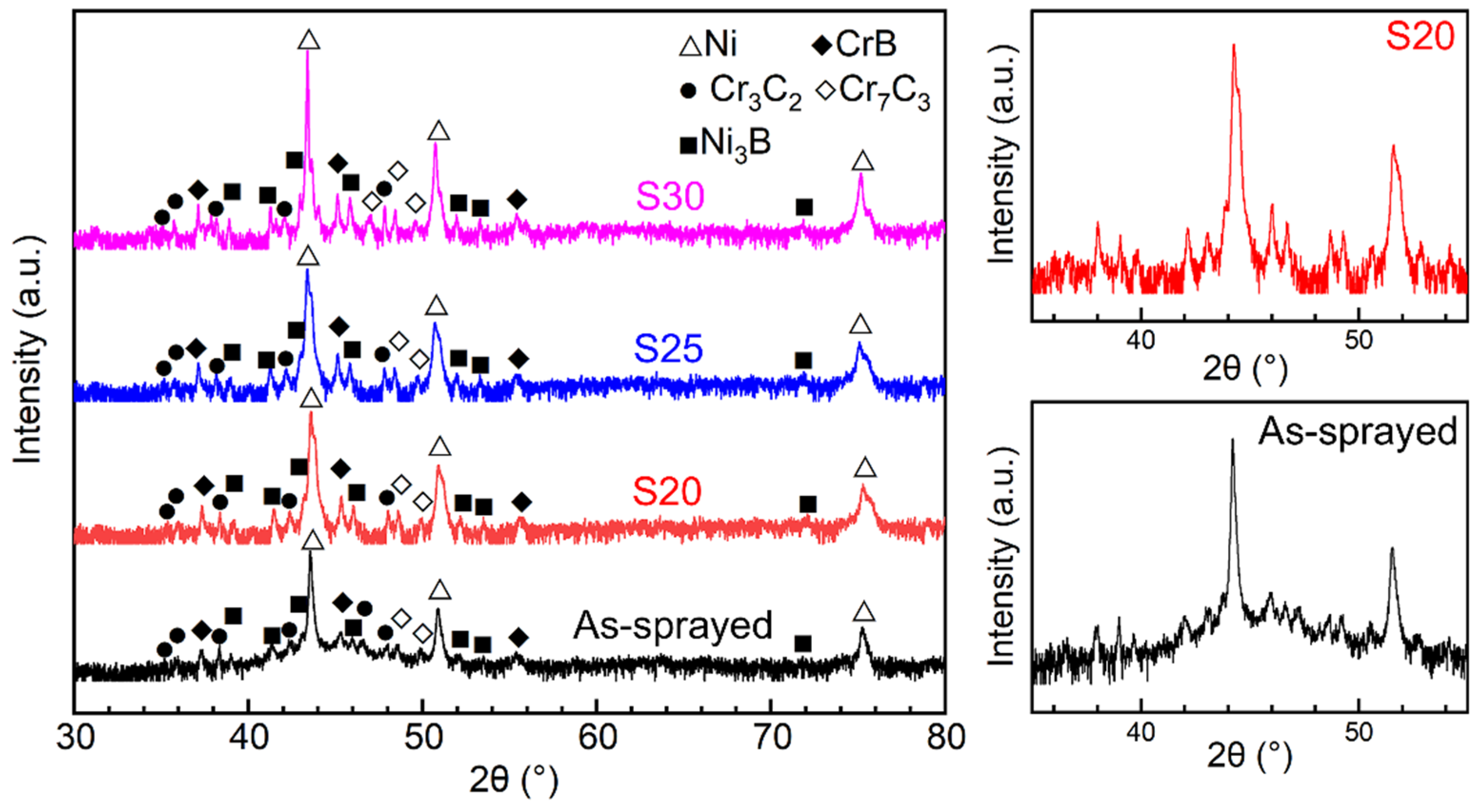
3.1. XRD Results

Figure 1 shows the XRD results for the as-sprayed, S20, S25, and S30 samples. Generally, five phases are observed for all samples, i.e., γ-Ni (ICCD#650380), Cr7C3 (ICCD#361482), Cr3C2 (ICCD#350804), Ni3B (ICCD#481223) and CrB (ICCD#260420). This finding is consistent with the results in the previous works [17,19]. It is known that the amorphous phase would be produced in the as-sprayed NiCrBSi coatings owing to the fast-cooling rate of in-flight particles in the spraying process [17]. Therefore, a broadened diffuse diffraction is found from 40° to 50° in the XRD pattern of the as-sprayed NiCrBSi coating (magnified view of XRD pattern for the as-sprayed coating sample), illustrating the presence of amorphous phase and/or nanocrystalline [17,25,26,27]. The amorphous phase is always in a meta-stable state and would be prone to crystallize when inputting the external energy (e.g., heat treatment or remelting) [17,19,28,29,30,31]. Therefore, the broad peaks become sharp in all remelted coating samples, elucidating that the remelting process works, and the amorphous phase is reduced or eliminated. For example, no broad diffuse diffraction is found for S20 (magnified view of XRD pattern for S20). To further understand the effect of the remelting process on the mechanical properties of coating/substrate interface, microstructural features of coating/substrate interfaces were investigated.

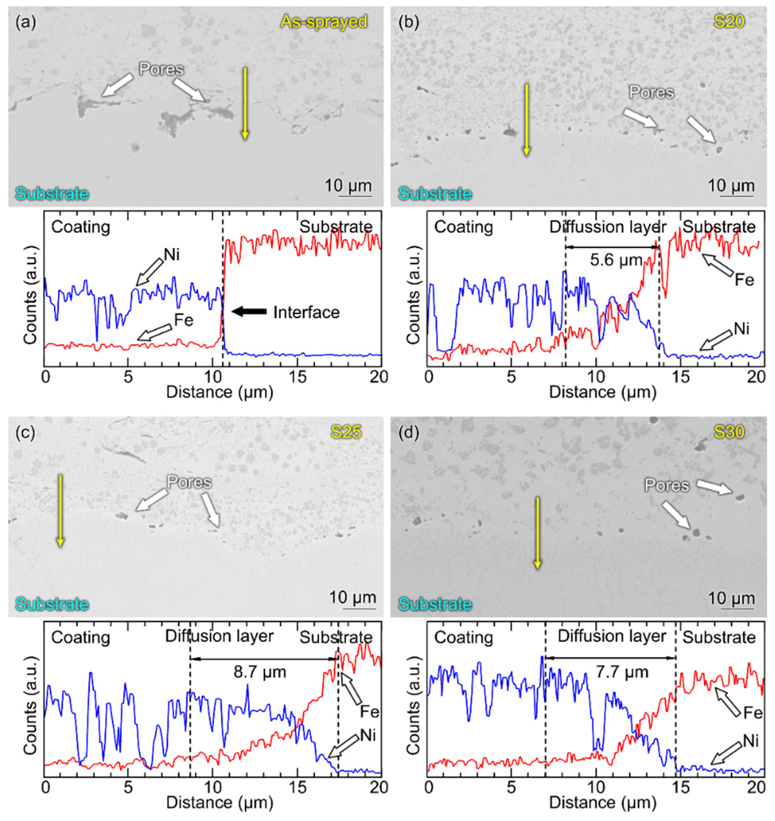
3.2. Analysis of the Pores at the Coating/Substrate Interfaces

Figure 2 shows the microstructural features of coating/substrate interfaces for different samples. A considerable number of pores are presented at the coating/substrate interface for the as-sprayed coating sample (Figure 2a), indicating a mechanical interlocking between the coating and substrate [23]. The pores at the coating/substrate interface are produced by the sandblasting and the stacking of in-flight particles [32]. Therefore, pores are widely found in the as-sprayed NiCrBSi coating [33,34,35]. The remelting process is frequently employed to improve the properties of the as-sprayed NiCrBSi coatings. As is well known, the remelting process input heat into the as-sprayed NiCrBSi coatings and eliminate the pores and lamellar boundaries in the coatings by diffusion or melt flow [36,37]. In such a situation, the porosities of NiCrBSi coatings would be reduced and their cohesion would correspondingly increase. After remelting at 20 kW, the number of the pores, as well as their sizes, are reduced (Figure 2b). With increasing the remelting power, the number and sizes of the pores continuously decrease (Figure 2c,d), indicating the increase in the contact regions between the coating and the substrate. In Ref. [38], micro-CT is used for quantificationally measuring the volumes of pores in both laboratory and industrial sectors. However, the size of the micro-CT sample is very limited. Using OM images may be more convenient for most laboratories and for economic industrial applications.
The interfacial pores are quantitatively investigated, including their area and number. Figure 3 reveals the distribution of interfacial pores for different samples. For all samples, lots of small pores (0~50 μm2) are distributed at the coating/substrate interface. For the as-sprayed sample, about 429 ± 73 pores with an area of 0~50 μm2 are found at the interface with the length of 1 mm. After remelting at the power of 20 kW, the number of pores decreases to 161 ± 38 per mm. With the increase in the remelting power, the number of pores sequentially decreases. Such a finding is also observed for the pores with the other areas (50~100 μm, 100~150 μm, and 150~500 μm). After remelting at 30 kW, pores are still found at the coating/substrate interface, indicating the existence of an imperfect metallurgical bonding. Even so, the remelting process significantly reduces the number of interfacial pores and increases the contact regions between the coating and the substrate.
Figure 4 shows the total area of pores at the coating/substrate interface. Undoubtedly, the as-sprayed NiCrBSi coating has the largest value of the total area of pores (904 ± 340 μm2) at the coating/substrate interface. The total area of pores significantly decreases after remelting. The total area of pores for S20 is only 719 ± 322 μm2, which is about 20.5% lower than that for the as-sprayed NiCrBSi coating. The elimination of pores can be attributed to two aspects: (i) the elemental diffusion at the edge of pores and (ii) the flow of melt filling the pores [19,20]. According to the previous work [19], the temperature of the coating surface is found to exceed 1500 °C when remelted at 30 kW. The melting point of NiCrBSi is about 1047 °C. Therefore, the as-sprayed NiCrBSi coating was melted and the pores are healed in the joint effect of diffusion and melt flow. In the other words, the healing of pores is mainly attributed to the input of heat to trigger the “diffusion” and/or “melt flow”. Hence, with increasing the remelting power, the total areas of interfacial pores continuously decrease. The total area of interfacial pore for S30 is only 171 ± 83 μm2, which is about 81% lower than that of the as-sprayed coating sample.

3.3. Diffusion Layer at the Coating/Substrate Interface

To investigate the diffusion layers (metallurgical bonding) at the contact regions of the coating/substrate interface, EDS analysis was carried out (Figure 5). SEM images show the interfacial microstructures of all coating samples. The SEM images were obtained under the backscattered electron mode. Under this mode, the contrast of the image is produced according to the weight of atoms. Therefore, even if it has a good focus, the images obtained under the backscattered electron mode have slightly lower quality than the ones obtained under the secondary electron mode. Meanwhile, the SEM images for the interfacial microstructures of coating samples are only used for SEM-EDS scanning and marking the locations of EDS line scanning but not for pores characterization. A detailed comparison between the microstructures of the as-sprayed and remelted NiCrBSi coatings can be found in our previous works [9,19]. Hence, only the interfacial microstructures of coating samples are shown here. The results are basically consistent with the outcome of OM observations (Figure 2). For the as-sprayed NiCrBSi coating, a considerable number of pores with irregular shapes are presented at the coat/substrate interface (Figure 5a). A yellow arrow is indicated at the coat/substrate interface to show the range of the EDS line scan. Ni is the primary element in the NiCrBSi coating and Fe is the main element in the substrate. Therefore, Ni and Fe are selected for investigating the elemental diffusion in the EDS analysis. EDS result indicates that the counts of Ni and Fe suddenly change at the coating/substrate interface (Figure 5a). Such a finding illustrates that a mechanical locking is presented at the coating/substrate interface of the as-sprayed NiCrBSi coating sample, even at the contact regions. After remelting, the diffusion layers are presented at the coating/substrate interface for S20, S25, and S30. As seen from Figure 5b–d, the counts of Ni and Fe gradually increase or decrease from coating to substrate, which is consistent with our previous work [19]. The sudden drops at the coating areas are attributed to the existence of particles (such as carbides and/or borides) in the coatings. Generally, the formation of diffusion layers would significantly improve the coating adhesion [39,40,41]. In the detected areas, the thicknesses of diffusion layers are 5.6 μm, 8.7 μm, and 7.7 μm, respectively. It is also reported that the thickness of the diffusion layer depends on the conditions of the interface in the as-sprayed coating sample; if lots of pores are presented at the local area of the interface, a thin diffusion layer would be found [19]. This reason accounts for the negative role of the pores in the interdiffusion of elements in the coating and substrate. Based on the results above, one can conclude that the discontinuous diffusion layers are formed after remelting at 20 kW, 25 kW, and 30 kW.

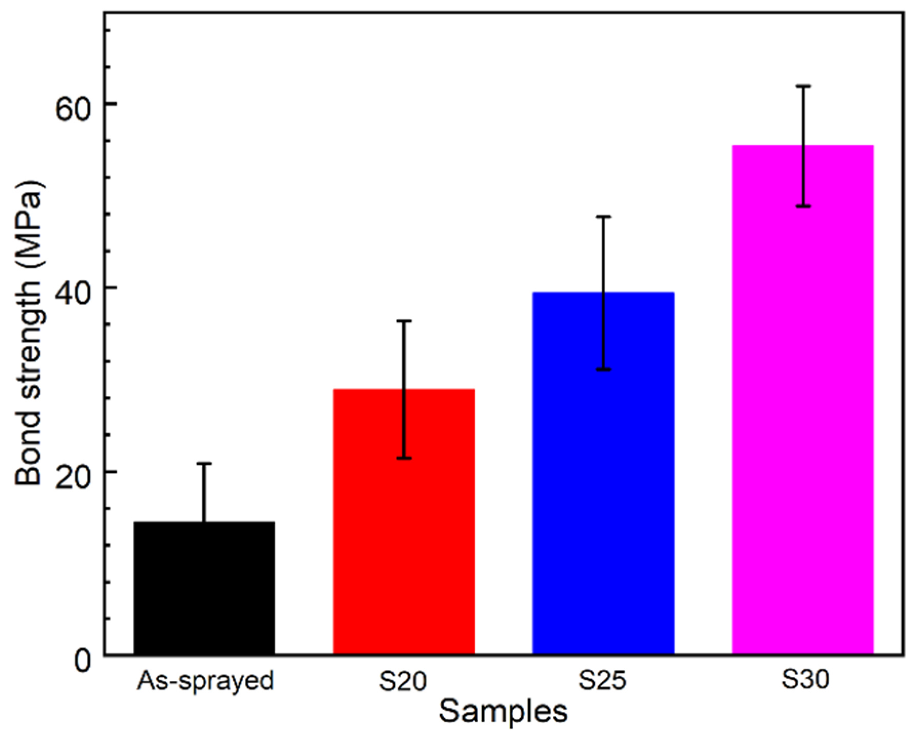
3.4. Mechanical Properties

The results of the hardness test are shown in Figure 6. The interfacial hardness is 305 ± 30 HV for the as-sprayed NiCrBSi coating. This value is similar to the outcome in Ref. [19]. After remelting, the interfacial hardness continuously increases with increasing the remelting power. The interfacial hardness is 347 ± 25 HV, 428 ± 23 HV, and 584 ± 18 HV, respectively. The pores in the coatings (as well as other materials) have a significant influence on their cohesion and thereby the hardness [42,43]. Similar to the porous materials, the pores would reduce their strength [44,45]. Therefore, the increase in the interfacial hardness of the remelted samples could be attributed to the elimination of the interfacial pores. Hence, as the number and total area of pores decrease, the interfacial hardness of the sample increases. Meanwhile, the formation of the diffusion layer also contributes to the enhancement of hardness. As seen from Figure 5, diffusion layers can be found in the contact regions between the coating and substrate for S20, S25, and S30. The diffusion layers have a gradual increase in thickness. Therefore, associated with the elimination of pores, the interfacial hardness of the remelted samples gradually increases.
The bond strength of all coating samples was measured. The as-sprayed NiCrBSi coating sample has a low bond strength of 14.5 ± 6.5 MPa. Generally, the bond strength of NiCrBSi coatings prepared by various spray technologies ranges from 11 to 60 MPa, lying on the spraying parameters used [22,23,24,46,47]. Such a low bond strength may become hidden trouble for the as-sprayed NiCrBSi coating during service. Therefore, the remelting process is frequently employed to improve the bond strength of as-sprayed NiCrBSi coating [48,49]. Similar to the hardness results, the bond strength of coatings is enhanced after remelting (Figure 7). S20 has a bond strength of 28.9 ± 7.5 MPa, which is about 100% higher than the as-sprayed NiCrBSi coating. Such an improvement can be attributed to the reduction in the interfacial pores and the formation of the diffusion layers. S25 and S30 have bond strengths of 39.4 ± 8.3 MPa and 55.4 ± 6.5 MPa. The bond strength of coatings continuously increases with increasing the remelting power, illustrating the formation of a better coating/substrate interface with the augments of remelting power.

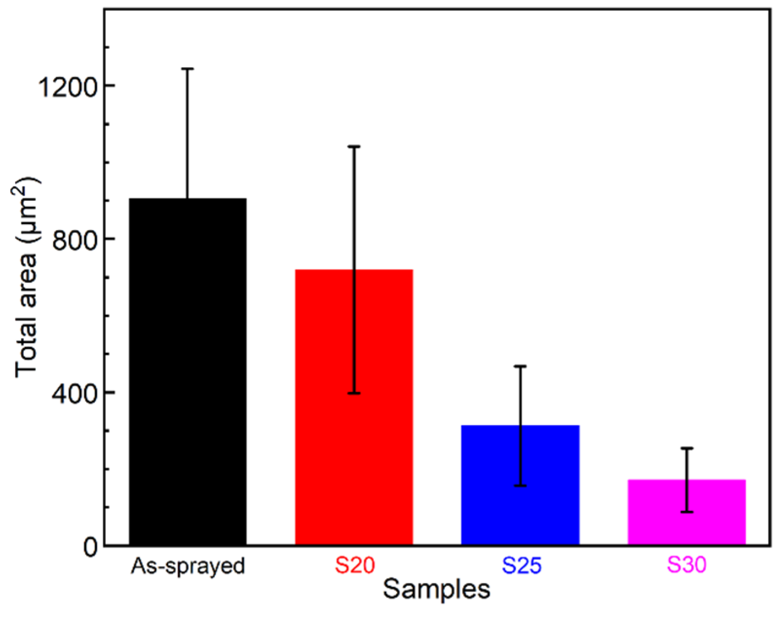
3.5. Relationship between the Total Areas of the Coating Samples and Their Mechanical Properties

The relationship between the total area of interfacial pores and bond strength of NiCrBSi coatings and the relationship between the total area of interfacial pores and interfacial hardness are plotted in Figure 8. Similar to other materials, the presence of pores decreases the strength of the materials or coating adhesion/cohesion [50,51,52,53]. A linear relationship between hardness and logarithmic value of total pore area is found. The slope of the fitted curve is −376. One should note that interfacial hardness would not decrease to zero owing to the hardness of the material itself. There are no previous works that can be referred to for fitting the relationship between the total area of interfacial pores and interfacial hardness. In this work, a logarithmic relationship is used. Other non-linear functions may also be used to fit this couple of relationships, such as exponential functions or other non-linear functions. For the fitted results, it can be observed that the decrease in the interfacial pores would significantly enhance the interfacial hardness. In Ref. [19], the 2Cr13 substrate has a hardness of 238 HV and the remelted NiCrBSi coating (almost free of pores and lamellar boundaries) has a hardness of 771–825 HV. Therefore, the interfacial hardness inevitable ranges from 238 HV to 825 HV in the remelted NiCrBSi coating.
Similar to the interfacial hardness, the bond strength of coating decreases with increasing the total area of interfacial pores. The bond strength generally has a linear relationship with the total area of the pores (Figure 8b). Hence, a linear equation is employed to fit the data. The result shows that the slope of the fitting curve is −0.05, indicating that the bond strength of coatings increases with decreasing the total area of pores. According to the fitting curve, when the total area of the pores decreases to zero, the bond strength would increase to 61.6 MPa. It has been reported that the bond strength is far away higher than this value in Refs. [19,21] because of the formation of metallurgical bonding between the coating and the substrate. The diffusion layer provides high adhesion for the coating [41,54,55]. The thickness of the diffusion layer would also contribute to the coating adhesion. However, to count up the thicknesses of diffusion layers at the contact regions at the coating/substrate interface is significantly difficult because the line scan of EDS is of high cost and the obtained value is also limited. As mentioned above, the thickness of the diffusion layer depends on the conditions of the interface in the as-sprayed coating sample. Therefore, the detected thickness of the diffusion layer has relative randomness. Only lots of data samples could exactly establish a believable relationship between the total area of interfacial pores and bond strength, especially at the significantly low level of interfacial pores. Even so, it also can be understood that excessive interfacial pores would significantly decrease the coating bond strength. The relationship between the total area of interfacial pores and bond strength of coatings basically obeys a linear law when the interfacial pores are still presented. If the total area of interfacial pores exceeds a value, the coating would be peeled off. For the applications of NiCrBSi coatings, their hardness plays an important role in the wear resistance, while the bond strength would determine their availability. Bond strength is the main focal point in this work. The built relationship between the total area of interfacial pores and bond strength of NiCrBSi coatings provides a good prediction for the bond strength of prepared NiCrBSi coatings. Owing to the influence of diffusion layers, the predicted bond strength may be slightly lower than the true value for the remelted NiCrBSi coatings. The conventional methods always cost many samples. This method only uses a small number of samples and can obtain a fitted equation for future use.
In this work, specific conditions for coating preparation were used. These conditions are also suitable for industrial applications. The developed method in this work is to explore a universal method for estimating the bond strength of prepared coatings. Therefore, selecting gradient parameters are beneficial to illustrate the method proposed in this work.
As known, the parameters of the spraying process have influences on the prepared NiCrBSi coatings in order to meet the industrial applications [19,51]. Lots of parameters are involved in the preparing process of plasma spraying. However, using more changed parameters may give more data and has a more accurate fitting result, which is not the main focus of this work. The selected parameters in both spraying and remelting are enough for illustrating this method. Endeavor has also been made to understand the relationship between the interfacial hardness and bond strength of the coatings. The interfacial hardness and bond strength are produced by the materials themselves and the contact regions of an interface, respectively. They have no intrinsic relationship. Therefore, it is hard to find the relationship between the interfacial hardness and bond strength. The method proposed in this work builds the relationship between interfacial pores and bond strength of NiCrBSi coating and opens the door for estimating the NiCrBSi coating adhesion by destructive methods, for example, applying CT scan to evaluate porosity at the interface.

4. Conclusions

In this work, the NiCrBSi coatings were prepared on the 2Cr13 stainless steel substrate. Subsequently, the remelting process was conducted on the as-sprayed NiCrBSi using the powers of 20 kW, 25 kW, and 30 kW, respectively. The investigations of the interfacial microstructures of the coating samples and their mechanical properties were systematically carried out.
The as-sprayed NiCrBSi coating has the total area of interfacial pores of 904 ± 304 μm2, the interfacial hardness of 305 ± 30 HV and the bond strength of 14.45 ± 6.45 MPa, respectively. The remelting process inputs heat to the as-sprayed NiCrBSi coating, reducing the interfacial pores of the remelted samples and correspondingly improving their interfacial hardness and bond strength with increasing the remelting powers. The sample remelted at 30 kW has the total area of interfacial pores of 171 ± 83 μm2, the interfacial hardness of 584 ± 18 HV and the bond strength of 55.42 ± 6.55 MPa, respectively.
The total area of interfacial pores and interfacial hardness basically have an exponential relationship. The interfacial hardness and total area of the pore is hard to fit. There may be multiple fits that can be used, which strongly depends on the nature of the coating and substrate materials. The total area of interfacial pores and bond strength primarily has a linear relationship, fitted by an equation of y = 0.05 x + 61.6 . The fitted results may help to predict the bond strength of prepared NiCrBSi coatings and the method mentioned in this work may have wider use.

Author Contributions

Conceptualization: L.-Y.C.; Methodology: L.-Y.C. and M.B.; Software: Y.-T.L. and Q.-H.Z.; Formal Analysis: Y.-T.L. and C.-H.Z.; Resources: Y.-T.L.; Data Curation: Y.-T.L. and H.-N.X.; Writing—Original Draft Preparation: L.-Y.C. and H.-N.X.; Writing—Review & Editing: L.-Y.C., J.-H.P. and S.L.; Supervision: S.L. and L.-C.Z.; Project Administration: L.-Y.C. and S.L.; Funding Acquisition: L.-Y.C. and L.-C.Z. All authors have read and agreed to the published version of the manuscript.

Funding

The authors would like to acknowledge the financial support provided by Jiangsu Province six talent peaks project (Grant No. XCL-117), Natural Science Foundation of Jiangsu (Grant No. BK20201456), and Open Foundation of Guangxi Key Laboratory of Processing for Non-ferrous Metals and Featured Materials (Grant No. 2020GXYSOF01 and 2021GXYSOF03).

Data Availability Statement

The raw/processed data required to reproduce these findings cannot be shared at this time as the data also forms part of an ongoing study.

Conflicts of Interest

The authors declare no conflict of interest.

References

  1. Zhang, L.-C.; Chen, L.-Y.; Wang, L. Surface Modification of Titanium and Titanium Alloys: Technologies, Developments and Future Interests. Adv. Eng. Mater. 2020, 22, 1901258. [Google Scholar] [CrossRef]
  2. Luscher, W.G.; Gilbert, E.R.; Pitman, S.G.; Love, E.F., Jr. Surface modification of Zircaloy-4 substrates with nickel zirconium intermetallics. J. Nucl. Mater. 2013, 433, 514–522. [Google Scholar] [CrossRef]
  3. Lei, J.; Shi, C.; Zhou, S.; Gu, Z.; Zhang, L.C. Enhanced corrosion and wear resistance properties of carbon fiber reinforced Ni-based composite coating by laser cladding. Surf. Coat. Technol. 2018, 334, 274–285. [Google Scholar] [CrossRef] [Green Version]
  4. Chen, L.-Y.; Liang, S.-X.; Liu, Y.; Zhang, L.-C. Additive manufacturing of metallic lattice structures: Unconstrained design, accurate fabrication, fascinated performances, and challenges. Mater. Sci. Eng. R Rep. 2021, 146, 100648. [Google Scholar] [CrossRef]
  5. Zhao, S.; Zhou, S.; Xie, M.; Dai, X.; Chen, D.; Zhang, L.-C. Phase separation and enhanced wear resistance of Cu88Fe12 immiscible coating prepared by laser cladding. J. Mater. Res. Technol. 2019, 8, 2001–2010. [Google Scholar] [CrossRef]
  6. Zhou, S.; Dai, X.; Xie, M.; Zhao, S.; Sercombe, T.B. Phase separation and properties of Cu-Fe-Cr-Si-C immiscible nanocomposite by laser induction hybrid cladding. J. Alloys Compd. 2018, 741, 482–488. [Google Scholar] [CrossRef]
  7. Wang, L.; Xie, L.; Lv, Y.; Zhang, L.-C.; Chen, L.; Meng, Q.; Qu, J.; Zhang, D.; Lu, W. Microstructure evolution and superelastic behavior in Ti-35Nb-2Ta-3Zr alloy processed by friction stir processing. Acta Mater. 2017, 131, 499–510. [Google Scholar] [CrossRef] [Green Version]
  8. Xu, C.; Chen, L.-Y.; Zheng, C.-B.; Zhang, H.-Y.; Zhao, C.-H.; Wang, Z.-X.; Lu, S.; Zhang, J.-W.; Zhang, L.-C. Improved Wear and Corrosion Resistance of Micro-Arc Oxidation Coatings on Ti–6Al–4V Alloy with Ultrasonic Assistance for Potential Biomedical Applications. Adv. Eng. Mater. 2021, 23, 2001433. [Google Scholar] [CrossRef]
  9. Chen, L.-Y.; Xu, T.; Wang, H.; Sang, P.; Lu, S.; Wang, Z.-X.; Chen, S.; Zhang, L.-C. Phase interaction induced texture in a plasma sprayed-remelted NiCrBSi coating during solidification: An electron backscatter diffraction study. Surf. Coat. Technol. 2019, 358, 467–480. [Google Scholar] [CrossRef]
  10. Chen, K.; Zeng, L.; Li, Z.; Chai, L.; Wang, Y.; Chen, L.-Y.; Yu, H. Effects of laser surface alloying with Cr on microstructure and hardness of commercial purity Zr. J. Alloys Compd. 2019, 784, 1106–1112. [Google Scholar] [CrossRef]
  11. Xiang, K.; Chen, L.-Y.; Chai, L.; Guo, N.; Wang, H. Microstructural characteristics and properties of CoCrFeNiNbx high-entropy alloy coatings on pure titanium substrate by pulsed laser cladding. Appl. Surf. Sci. 2020, 517, 146214. [Google Scholar] [CrossRef]
  12. Hong, Y.-L.; Liu, Z.; Wang, L.; Zhou, T.; Ma, W.; Xu, C.; Feng, S.; Chen, L.; Chen, M.-L.; Sun, D.-M. Chemical vapor deposition of layered two-dimensional MoSi2N4 materials. Science 2020, 369, 670–674. [Google Scholar] [CrossRef]
  13. Bergant, Z.; Trdan, U.; Grum, J. Effect of high-temperature furnace treatment on the microstructure and corrosion behavior of NiCrBSi flame-sprayed coatings. Corros. Sci. 2014, 88, 372–386. [Google Scholar] [CrossRef]
  14. Hong, S.; Wu, Y.; Li, G.; Wang, B.; Gao, W.; Ying, G. Microstructural characteristics of high-velocity oxygen-fuel (HVOF) sprayed nickel-based alloy coating. J. Alloys Compd. 2013, 581, 398–403. [Google Scholar] [CrossRef]
  15. Liu, S.-H.; Li, C.-X.; Zhang, H.-Y.; Zhang, S.-L.; Li, L.; Xu, P.; Yang, G.-J.; Li, C.-J. A novel structure of YSZ coatings by atmospheric laminar plasma spraying technology. Scr. Mater. 2018, 153, 73–76. [Google Scholar] [CrossRef]
  16. Smovzh, D.V.; Sakhapov, S.Z.; Zaikovskii, A.V.; Chernova, S.A.; Novopashin, S.A. Formation mechanism of MgO hollow nanospheres via calcination of C-MgO composite produced by electric arc spraying. Ceram. Int. 2019, 45, 7338–7343. [Google Scholar] [CrossRef]
  17. Chen, L.-Y.; Xu, T.; Lu, S.; Wang, Z.-X.; Chen, S.; Zhang, L.-C. Improved hardness and wear resistance of plasma sprayed nanostructured NiCrBSi coating via short-time heat treatment. Surf. Coat. Technol. 2018, 350, 436–444. [Google Scholar] [CrossRef]
  18. Ratha, I.; Datta, P.; Balla, V.K.; Nandi, S.K.; Kundu, B. Effect of doping in hydroxyapatite as coating material on biomedical implants by plasma spraying method: A review. Ceram. Int. 2021, 47, 4426–4445. [Google Scholar] [CrossRef]
  19. Chen, L.-Y.; Wang, H.; Zhao, C.; Lu, S.; Wang, Z.-X.; Sha, J.; Chen, S.; Zhang, L.-C. Automatic remelting and enhanced mechanical performance of a plasma sprayed NiCrBSi coating. Surf. Coat. Technol. 2019, 369, 31–43. [Google Scholar] [CrossRef]
  20. Sha, J.; Chen, L.-Y.; Liu, Y.-T.; Yao, Z.-J.; Lu, S.; Wang, Z.-X.; Zang, Q.-H.; Mao, S.-H.; Zhang, L.-C. Phase Transformation-Induced Improvement in Hardness and High-Temperature Wear Resistance of Plasma-Sprayed and Remelted NiCrBSi/WC Coatings. Metals 2020, 10, 1688. [Google Scholar] [CrossRef]
  21. Tian, J.J.; Yao, S.W.; Luo, X.T.; Li, C.X.; Li, C.J. An effective approach for creating metallurgical self-bonding in plasma-spraying of NiCr-Mo coating by designing shell-core-structured powders. Acta Mater. 2016, 110, 19–30. [Google Scholar] [CrossRef]
  22. Bergant, Z.; Grum, J. Quality improvement of flame sprayed, heat treated, and remelted NiCrBSi coatings. J. Therm. Spray Technol. 2009, 18, 380–391. [Google Scholar] [CrossRef]
  23. Zhang, M.; Li, Y.N.; Zhang, F.C.; Wang, X.B.; Chen, L.Y.; Yang, Z.N. Effect of annealing treatment on the microstructure and mechanical properties of a duplex Zr-2.5 Nb alloy. Mater. Sci. Eng. A 2017, 706, 236–241. [Google Scholar] [CrossRef]
  24. Wang, Y.Y.; Li, C.J.; Ohmori, A. Examination of factors influencing the bond strength of high velocity oxy-fuel sprayed coatings. Surf. Coat. Technol. 2006, 200, 2923–2928. [Google Scholar] [CrossRef]
  25. Zhang, L.C.; Xu, J. Glass-forming ability of melt-spun multicomponent (Ti, Zr, Hf)–(Cu, Ni, Co)–Al alloys with equiatomic substitution. J. Non-Cryst. Solids 2004, 347, 166–172. [Google Scholar] [CrossRef]
  26. Zhang, L.C.; Shen, Z.Q.; Xu, J. Mechanically milling-induced amorphization in Sn-containing Ti-based multicomponent alloy systems. Mater. Sci. Eng. A 2005, 394, 204–209. [Google Scholar] [CrossRef]
  27. Zhang, L.C.; Xu, J.; Ma, E. Consolidation and properties of ball-milled Ti50Cu18Ni22Al4Sn6 glassy alloy by equal channel angular extrusion. Mater. Sci. Eng. A 2006, 434, 280–288. [Google Scholar] [CrossRef]
  28. Zhang, L.C.; Xu, J.; Ma, E. Mechanically Alloyed Amorphous Ti50(Cu0.45Ni0.55)44–xAlxSi4B2 Alloys with Supercooled Liquid Region. J. Mater. Res. 2002, 17, 1743–1749. [Google Scholar] [CrossRef] [Green Version]
  29. Jia, Z.; Duan, X.; Zhang, W.; Wang, W.; Sun, H.; Wang, S.; Zhang, L.-C. Ultra-sustainable Fe78Si9B13 metallic glass as a catalyst for activation of persulfate on methylene blue degradation under UV-VIS light. Sci. Rep. 2016, 6, 38520. [Google Scholar] [CrossRef] [PubMed]
  30. Jia, Z.; Wang, Q.; Sun, L.; Wang, Q.; Zhang, L.-C.; Wu, G.; Luan, J.-H.; Jiao, Z.-B.; Wang, A.; Liang, S.-X.; et al. Attractive In Situ Self-Reconstructed Hierarchical Gradient Structure of Metallic Glass for High Efficiency and Remarkable Stability in Catalytic Performance. Adv. Funct. Mater. 2019, 29, 1807857. [Google Scholar] [CrossRef]
  31. Zhang, L.-C.; Kim, K.B.; Yu, P.; Zhang, W.Y.; Kunz, U.; Eckert, J. Amorphization in mechanically alloyed (Ti, Zr, Nb)-(Cu, Ni)-Al equiatomic alloys. J. Alloys Compd. 2007, 428, 157–163. [Google Scholar] [CrossRef]
  32. Cui, Y.-H.; Hu, Z.-C.; Ma, Y.-D.; Yang, Y.; Zhao, C.-C.; Ran, Y.-T.; Gao, P.-Y.; Wang, L.; Dong, Y.-C.; Yan, D.-R. Porous nanostructured ZrO2 coatings prepared by plasma spraying. Surf. Coat. Technol. 2019, 363, 112–119. [Google Scholar] [CrossRef]
  33. Liu, L.; Xu, H.; Xiao, J.; Wei, X.; Zhang, G.; Zhang, C. Effect of heat treatment on structure and property evolutions of atmospheric plasma sprayed NiCrBSi coatings. Surf. Coat. Technol. 2017, 325, 548–554. [Google Scholar] [CrossRef]
  34. Xiao, J.-K.; Wu, Y.-Q.; Zhang, W.; Chen, J.; Wei, X.-L.; Zhang, C. Microstructure, wear and corrosion behaviors of plasma sprayed NiCrBSi-Zr coating. Surf. Coat. Technol. 2019, 360, 172–180. [Google Scholar] [CrossRef]
  35. Zhou, Y.-X.; Zhang, J.; Xing, Z.-G.; Wang, H.-D.; Lv, Z.-L. Microstructure and properties of NiCrBSi coating by plasma cladding on gray cast iron. Surf. Coat. Technol. 2019, 361, 270–279. [Google Scholar] [CrossRef]
  36. Yang, X.C.; Li, G.; Wang, H.; Dong, T.; Kang, J. Effect of flame remelting on microstructure and wear behaviour of plasma sprayed NiCrBSi-30%Mo coating. Surf. Eng. 2018, 34, 181–188. [Google Scholar] [CrossRef]
  37. Kong, D.; Zhao, B. Effects of loads on friction–wear properties of HVOF sprayed NiCrBSi alloy coatings by laser remelting. J. Alloys Compd. 2017, 705, 700–707. [Google Scholar] [CrossRef]
  38. Liu, Y.J.; Li, S.J.; Wang, H.L.; Hou, W.T.; Hao, Y.L.; Yang, R.; Sercombe, T.B.; Zhang, L.C. Microstructure, defects and mechanical behavior of beta-type titanium porous structures manufactured by electron beam melting and selective laser melting. Acta Mater. 2016, 113, 56–67. [Google Scholar] [CrossRef] [Green Version]
  39. Chalker, P.R.; Bull, S.J.; Rickerby, D.S. A review of the methods for the evaluation of coating-substrate adhesion. Mater. Sci. Eng. A 1991, 140, 583–592. [Google Scholar] [CrossRef]
  40. Rickerby, D.S. A review of the methods for the measurement of coating-substrate adhesion. Surf. Coat. Technol. 1988, 36, 541–557. [Google Scholar] [CrossRef]
  41. Chen, Z.; Zhou, K.; Lu, X.; Lam, Y.C. A review on the mechanical methods for evaluating coating adhesion. Acta Mech. 2014, 225, 431–452. [Google Scholar] [CrossRef]
  42. Zhou, H.; Li, C.; Yang, H.; Luo, X.; Yang, G.; Li, W.; Hussain, T.; Li, C. Pores Structure Change Induced by Heat Treatment in Cold-Sprayed Ti6Al4V Coating. J. Therm. Spray Technol. 2019, 28, 1199–1211. [Google Scholar] [CrossRef]
  43. Chen, L.-Y.; Zhang, H.-Y.; Zheng, C.; Yang, H.-Y.; Qin, P.; Zhao, C.; Lu, S.; Liang, S.-X.; Chai, L.; Zhang, L.-C. Corrosion behavior and characteristics of passive films of laser powder bed fusion produced Ti–6Al–4V in dynamic Hank’s solution. Mater. Des. 2021, 208, 109907. [Google Scholar] [CrossRef]
  44. Wang, L.; Xie, L.; Zhang, L.-C.; Chen, L.; Ding, Z.; Lv, Y.; Zhang, W.; Lu, W.; Zhang, D. Microstructure evolution and superelasticity of layer-like NiTiNb porous metal prepared by eutectic reaction. Acta Mater. 2018, 143, 214–226. [Google Scholar] [CrossRef]
  45. Liu, Y.J.; Li, S.J.; Zhang, L.C.; Hao, Y.L.; Sercombe, T.B. Early plastic deformation behaviour and energy absorption in porous β-type biomedical titanium produced by selective laser melting. Scr. Mater. 2018, 153, 99–103. [Google Scholar] [CrossRef]
  46. Vencl, A.; Arostegui, S.; Favaro, G.; Zivic, F.; Mrdak, M.; Mitrović, S.; Popovic, V. Evaluation of adhesion/cohesion bond strength of the thick plasma spray coatings by scratch testing on coatings cross-sections. Tribol. Inter. 2011, 44, 1281–1288. [Google Scholar] [CrossRef]
  47. Li, C.-J.; Wang, Y.-Y. Effect of particle state on the adhesive strength of HVOF sprayed metallic coating. J. Therm. Spray Technol. 2002, 11, 523–529. [Google Scholar] [CrossRef]
  48. Dhakar, B.M.; Dwivedi, D.K.; Sharma, S.P. Studies on remelting of tungsten carbide and rare earth modified nickel base alloy composite coating. Surf. Eng. 2012, 28, 73–80. [Google Scholar] [CrossRef]
  49. Karimi, M.R.; Salimijazi, H.R.; Golozar, M.A. Effects of remelting processes on porosity of NiCrBSi flame sprayed coatings. Surf. Eng. 2016, 32, 238–243. [Google Scholar] [CrossRef]
  50. Liu, S.; Han, S.; Zhang, L.; Chen, L.-Y.; Wang, L.; Zhang, L.; Tang, Y.; Liu, J.; Tang, H.; Zhang, L.-C. Strengthening mechanism and micropillar analysis of high-strength NiTi–Nb eutectic-type alloy prepared by laser powder bed fusion. Compos. Part B 2020, 200, 108358. [Google Scholar] [CrossRef]
  51. Sang, P.; Chen, L.-Y.; Zhao, C.; Wang, Z.-X.; Wang, H.; Lu, S.; Song, D.; Xu, J.-H.; Zhang, L.-C. Particle Size-Dependent Microstructure, Hardness and Electrochemical Corrosion Behavior of Atmospheric Plasma Sprayed NiCrBSi Coatings. Metals 2019, 9, 1342. [Google Scholar] [CrossRef] [Green Version]
  52. Zhao, B.; Gain, A.K.; Ding, W.; Zhang, L.; Li, X.; Fu, Y. A review on metallic porous materials: Pore formation, mechanical properties, and their applications. Int. J. Adv. Manuf. Technol. 2018, 95, 2641–2659. [Google Scholar] [CrossRef]
  53. Domínguez-Trujillo, C.; Peón, E.; Chicardi, E.; Pérez, H.; Rodríguez-Ortiz, J.A.; Pavón, J.J.; García-Couce, J.; Galván, J.C.; García-Moreno, F.; Torres, Y. Sol-gel deposition of hydroxyapatite coatings on porous titanium for biomedical applications. Surf. Coat. Technol. 2018, 333, 158–162. [Google Scholar] [CrossRef]
  54. Serres, N.; Hlawka, F.O.; Costil, S.; Langlade, C.; Machi, F. Microstructures of Metallic NiCrBSi Coatings Manufactured via Hybrid Plasma Spray and In Situ Laser Remelting Process. J. Therm. Spray Technol. 2011, 20, 336–343. [Google Scholar] [CrossRef] [Green Version]
  55. Serres, N.; Hlawka, F.; Costil, S.; Langlade, C.; MacHi, F. Microstructures and mechanical properties of metallic NiCrBSi and composite NiCrBSi-WC layers manufactured via hybrid plasma/laser process. Appl. Surf. Sci. 2011, 257, 5132–5137. [Google Scholar] [CrossRef]
Figure 1. XRD patterns of all coating samples. The two figures on the right are the magnified view of the XRD patterns of the as-sprayed and S20 between 35° and 50°. S20, S25, and S30 indicate the as-sprayed NiCrBSi coatings remelted at 20 kW, 25 kW, and 30 kW.
Metals 12 00168 g001
Figure 2. Optical images for the microstructural features of coating/substrate interfaces for different samples: (a) as-sprayed, (b) S20, (c) S25, and (d) S30 coating samples. S20, S25, and S30 indicate the as-sprayed NiCrBSi coatings remelted at 20 kW, 25 kW, and 30 kW. The pores in the images are representative but not quantitative.
Metals 12 00168 g002
Figure 3. Size distribution of interfacial pores for the as-sprayed, S20, S25, and S30 samples. S20, S25, and S30 indicate the as-sprayed NiCrBSi coatings remelted at 20 kW, 25 kW, and 30 kW.
Metals 12 00168 g003
Figure 4. Total areas of interfacial pores for the as-sprayed, S20, S25, and S30 coating samples. S20, S25, and S30 indicate the as-sprayed NiCrBSi coatings remelted at 20 kW, 25 kW, and 30 kW.
Metals 12 00168 g004
Figure 5. SEM observations for the interface morphologies of (a) the as-sprayed, (b) S20, (c) S25, and (d) S30 coating samples and their corresponding line scanning profiles of Ni and Fe elements at the interfaces. S20, S25, and S30 indicate the as-sprayed NiCrBSi coatings remelted at 20 kW, 25 kW, and 30 kW. The yellow arrows indicate the routes of EDS line scan.
Metals 12 00168 g005
Figure 6. Interfacial hardness of the as-sprayed NiCrBSi, S20, S25, and S30 samples. S20, S25, and S30 indicate the as-sprayed NiCrBSi coatings remelted at 20 kW, 25 kW, and 30 kW.
Metals 12 00168 g006
Figure 7. Bond strength of the as-sprayed NiCrBSi, S20, S25 and S30 samples. S20, S25, and S30 indicate the as-sprayed NiCrBSi coatings remelted at 20 kW, 25 kW, and 30 kW.
Metals 12 00168 g007
Figure 8. Relationship between the total areas of the coating samples and their mechanical properties: (a) interfacial hardness and (b) bond strength.
Metals 12 00168 g008
Table 1. Chemical compositions of NiCrBSi powder and stainless-steel substrate (in wt%).
ElementsCSiBCrMnTiFeNi
NiCrBSi powder0.64.53.016.2----5.3Bal.
Stainless-steel substrate0.20.8--13.00.80.2Bal.0.6
Table 2. Plasma spraying and remelting parameters selected.
ParametersSprayingRemelting
123
Voltage (V)60455050
Current (A)500460500600
Powder feed rate (g/min)18--
Spray step (mm)3333
Gun traverse rate (mm/s)100101010
Main gas Ar (slpm)254254254254
Secondary gas N2 (slpm)58585858
Feed gas Ar (slpm)127127127127
Spray distance (mm)80505050
Pass6333
Publisher’s Note: MDPI stays neutral with regard to jurisdictional claims in published maps and institutional affiliations.

