Article

Understanding the Micro-Mechanical Behaviour of Recast Layer Formed during WEDM of Titanium Alloy

1
Adelaide Microscopy, The University of Adelaide, Adelaide, SA 5000, Australia
2
School of Civil and Mechanical Engineering, Curtin University, Bentley, WA 6102, Australia
3
School of Mechanical Engineering, Lovely Professional University, Phagwara 144411, India
4
Department of Mechatronics Engineering, Kongu Engineering College, Erode 638060, India
5
Department of Mechanical Engineering, Faculty of Engineering and Science, Curtin University, Miri 98009, Malaysia
*
Author to whom correspondence should be addressed.
Metals 2022, 12(2), 188; https://doi.org/10.3390/met12020188 (registering DOI)
Submission received: 14 December 2021 / Revised: 12 January 2022 / Accepted: 14 January 2022 / Published: 20 January 2022
(This article belongs to the Special Issue Advancements in Machining Technologies of Titanium-Based Alloys)

Abstract

:
In the course of wire electro-discharge machining (WEDM), the unavoidable and undesirable formation of a recast layer on titanium (Ti) alloy was observed to have taken place. As a result, subsequent processing steps are required to remove this recast layer. In order to facilitate its removal, this study investigates the micro-mechanical properties of the said recast layer to better understand them. To that end, micro-pillars were fabricated on a recast layer after which in situ micro-pillar compression and nanoindentation were carried out. The in situ compression technique helps visualize deformation of materials in real time with corresponding features in stress–strain curves. The recast layer exhibits relatively brittle behaviour associated with the heat-affected zone (HAZ) and base alloy. Whereas the base alloy experienced substantial work hardening as evidenced by the formation of slip/shear bands, the recast layer was found to break down under external loading without any visible strain accommodation. This understanding of the recast layers could facilitate the design of effective removal operations, saving time and money. In addition, the recast layer might be useful in some applications.

1. Introduction

Electro-discharge machining (EDM) is a technique used to machine hard-to-cut metals/alloys such as titanium (Ti). When a wire is used as an electrode during the EDM process, the technique is called wire electro-discharge machining (WEDM) [1]. WEDM is a widely practiced manufacturing process to machine slots and complex shapes in hard-to-cut materials, for example, metal matrix composites (MMCs) [2], duplex stainless steel [3], Inconel [4], Ti-alloys [5,6] and HSLA steel [7].
After the WEDM process has been carried out, the resultant machined surface becomes not only rough, but also contains several sub-surface layers. The outermost layer is widely known as the recast layer, as described by Pramanik et al. [5], followed by the heat-affected zone (HAZ) in some cases and the base material. The formation of such sub-surface layers is reported in the literature for a number of different materials. For example, in the case of Al-MMCs it has been documented by Zhenlong et al. [8] that the roughness (Ra) of the machined surface is in the range of 1.1–2.2 µm and thickness of recast layer is 15–20 µm. For Inconel, the roughness (Ra) of the machined surface ranged from 2.2–3.53 µm with the recast layer thickness up to 9 µm, as reported by Aspinwall et al. [9] and Newton et al. [10]. High-strength steel such as HSLA exhibits a much thicker recast layer (13–30 µm), with relatively high roughness (Ra) in the range of 4–7 µm as reported by Azam et al. [7]. In the case of Ti-alloy (Ti6Al4V), the surface roughness (Ra) ranged from 2.6–3.4 µm, with the presence of both recast layer (10–20 µm) as reported by Aspinwall et al. [9] and Mouralova et al. [11], and HAZ (3–6 µm) as reported by Pramanik et al. [5] and Hasçalık et al. [12].
The formation of such a recast layer is unavoidable, as it is an inherent material removal mechanism of the WEDM process. This process involves softening and meltdown of materials in the WEDM zone, followed by vaporisation of molten materials. As a result, a portion of the molten materials is redeposited and resolidifies in the presence of the electrolyte, forming the recast layer. In contrast, development of the HAZ is related to the thermal conductivity of the workpiece materials in question [6,13]. In the case of Al-MMC, there is no presence of HAZ due its high thermal conductivity (170–200 W/m·K) as reported by Novich et al. [14], which is not the case for Ti-alloy and Inconel, with thermal conductivity of 7.1–7.3 W/m·K as reported by Risegari et al. [15] and 10.9–11.2 W/m·K as reported by Sweet et al. [16]. As a result of the low thermal conductivity of those materials, heat generated from the WEDM process cannot dissipate quickly enough through the workpiece material, and thus build-up of heat next to the recast layer gives rise to the HAZ, which is simply a tempered zone of the original microstructure of the base materials, as reported by Hasçalık et al. [12]. The extent of the different layers (recast layer and HAZ) that form during the WEDM process cannot be eliminated but can be minimized by varying input parameters of the WEDM process.
The presence of a recast layer is undesirable in the final workpiece, as it is generally brittle in nature and contains cracks and pores. Such cracks and pores can trap corrosive media during service, and act as crack initiation sites for parts in service. As reported by Xu et al. [17] such a recast layer can be reduced by using a coated tool, however, it cannot be eliminated fully. In practice, following the WEDM process workpiece materials are treated with various subsequent methods to remove such recast layers, such as grit blasting, as reported by Holmberg et al. [18]; micro-blasting/abrasive blasting, as reported by Qua et al. [19]; etching as reported by Wang et al. [20]; mechanical grinding, as reported by Qua et al. [19]; and magnetic abrasive finishing, as reported by Khangura et al. [21].
Recently, Mouralova et al. [22] reported changes in microstructure of the Ti-alloy machined by WEDM and noted the presence of a recast layer. For the successful removal of these recast layers, it is necessary to have a complete understanding of them in terms of their structure, extent, and mechanical properties. Although some information on their structure and extent is available in literature for some materials, information on their mechanical properties is completely absent. Without proper knowledge of a recast layer’s mechanical properties, subsequent removal processes cannot be optimized. This can result in under/over-removal of a recast layer and compromise the dimensional accuracy/tolerance of parts for required applications. Better understanding of recast layers will not only facilitate the design of an effective removal operation, but also save both time and money.
Historically, to investigate the mechanical properties of a recast layer and HAZ, researchers have been solely dependent on nanoindentation techniques which only offer hardness and Young’s modulus, without any information on stress–strain behaviour. This is because the recast layer and HAZ have limited thickness, which prohibit the fabrication of ‘dog-bone’ type samples for traditional tensile testing. Thus, it is evident that proper documentation of stress–strain behaviour of both the recast layer and HAZ has been undermined, primarily due to limitations on the investigational setup. With advancement in in situ fabrication and testing, this limitation can be overcome using micro-pillar compression under in situ conditions as successfully demonstrated by Kurdi et al. [23] on electrodeposited multilayered coatings, and on bulk materials by Basak et al. [24]. Such techniques not only provide stress–strain curves, but also correlate different features of the stress–strain curve with the physical state of the micro-pillar in the course of compression via video recording of the process.
Therefore, the goal of the present research was to understand the mechanical properties of recast layer formed on Ti6Al4V alloy during WEDM processing. To achieve that, nanoindentation and micro-pillar compression were carried out on a recast layer, HAZ, and base alloy followed by detailed electron microscopy investigation of deformed micro-pillars. The outcome of this study will facilitate the design of appropriate subsequent post-processing techniques to remove the recast layer prior to application. The steps that are required to remove the recast layer were not investigated in the current study, as it was out of the scope of the present research objectives.

2. Materials and Methodology

WEDM was performed on a Ti6Al4V alloy slab with a thickness of 9 mm by a FANUC ROBOCUT α 0iD machine. The aim was to produce blocks of cylindrical shape with a diameter of 12 mm and height of 9 mm. The machining parameters that were used during the operation were as follows: 4 ms pulse on time, 26 ms pulse off time, flushing pressure of 15 MPa, flushing rate of 10 L/min, open circuit voltage of 85 V, wire speed of 10 m/min, servo voltage of 20 V and wire tension of 1400 gf together with deionized water as di-electric medium. The wire electrode was a Ø 0.25 mm brass wire that was coated with a thin layer of zinc. The machining parameters that were used in the present research was selected based on the optimization of parameters as reported by Pramanik et al. [2] on the same material. Figure 1 shows the optical photograph of the cylindrical block together with the location of machined surface, recast layer and heat affected zone (overlaid). After machining, cylindrical blocks were mounted with cold resin and subjected to metallographic polishing. Metallographic polishing was carried out on a Struers automated metallographic polisher using progressively finer grades of diamond slurry. Surface and cross-section of the samples were examined by scanning electron microscope (SEM) (Quanta 450, FEI).
Nanoindentation was carried out on a PI-88 nanoindentor (Hysitron Inc., Minneapolis, MN, USA) and a diamond Berkovich tip was used as the indenter. The tip was a three-sided pyramid with an inclination angle of 142.3°, half angle (ψ) of 65.35° with about 150 nm tip radius as reported by Basak et al. [25]. Indentation load (Fmax) was 10 mN together with loading/unloading rates of 0.5 mN/s. At peak load, there was a holding time of 5 s to allow stability before unloading. In each sub-surface layer, at least 10 individual indentations were carried out to ensure repeatability, and average values were reported for result analysis and discussion.
In order to fabricate the micro-pillars, an SEM incorporated with a Ga+ focused beam (FIB-SEM) was employed. To make sure that the indenter did not touch the sample surface, except the micro-pillars in the course of compression, a sufficient void was kept (30 µm) between the micro-pillar and surrounding materials. At first, the milling pattern was executed at relatively higher current (6.5 nA current at 30 kV) followed by final polishing at 0.46 nA at 30 kV. For the in situ compression test, the indenter tip was swapped with a 5 µm diameter flat diamond on the same nanoindentation system. During in situ compression, the loading and unloading rate was 3 and 50 nm/s respectively, where the strain rate was equivalent to 10−3 s−1. The load–displacement graphs were recorded together with corresponding video of the compression. The load–displacement curves were converted to stress–strain curves according to the method reported by Misra et al. [26]. This method was also used by Kurdi et al. [23] on in situ compression of Co/Sn multi-layered coatings and Basak et al. [24] on SiC-reinforced metal matrix composites (MMCs). To validate the results and confirm the reputability, a minimum of five separate micro-pillar compressions were done on each sub-surface layer, resulting in 15 individual in situ compressions altogether.

3. Results and Discussion

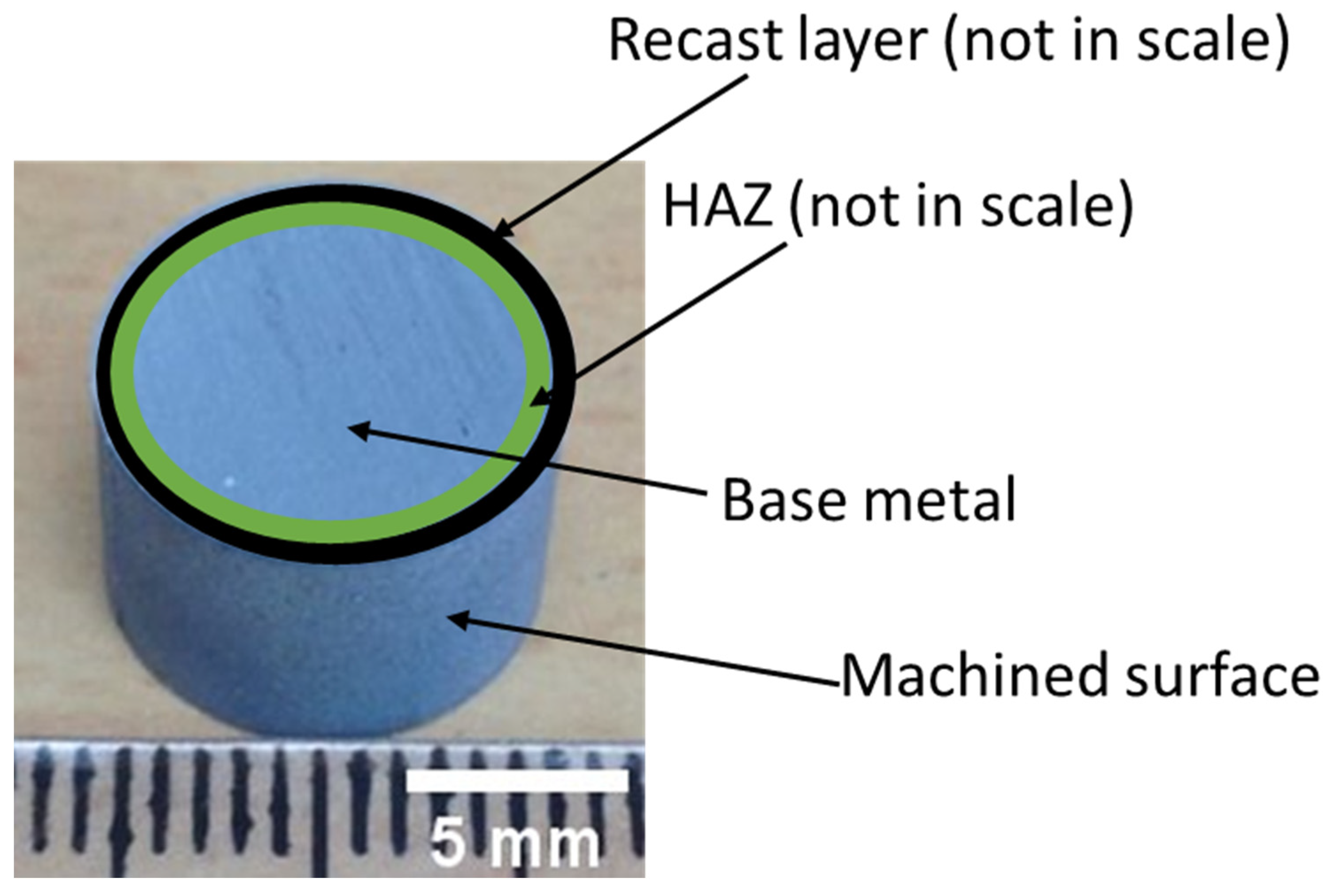
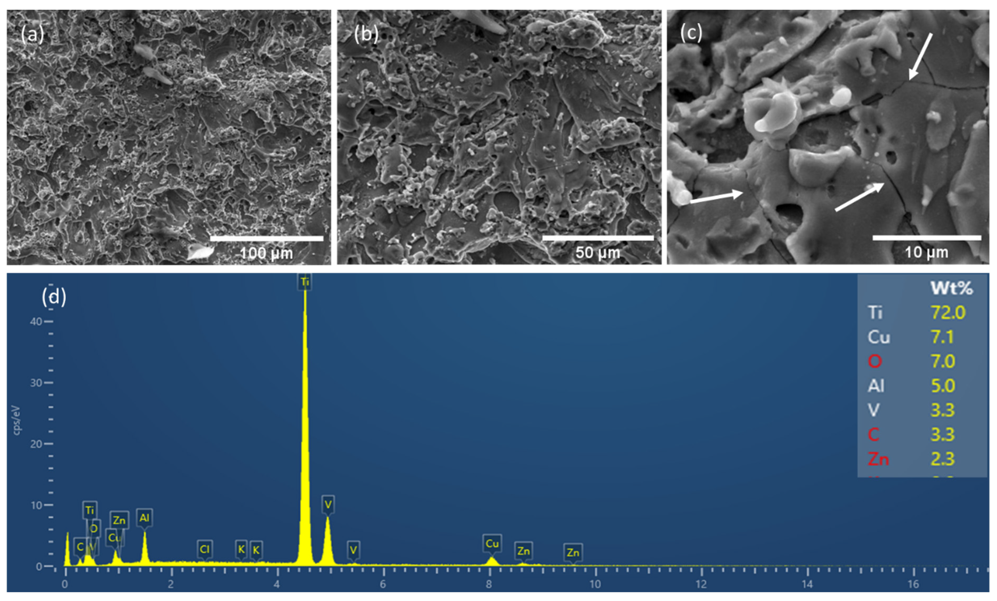
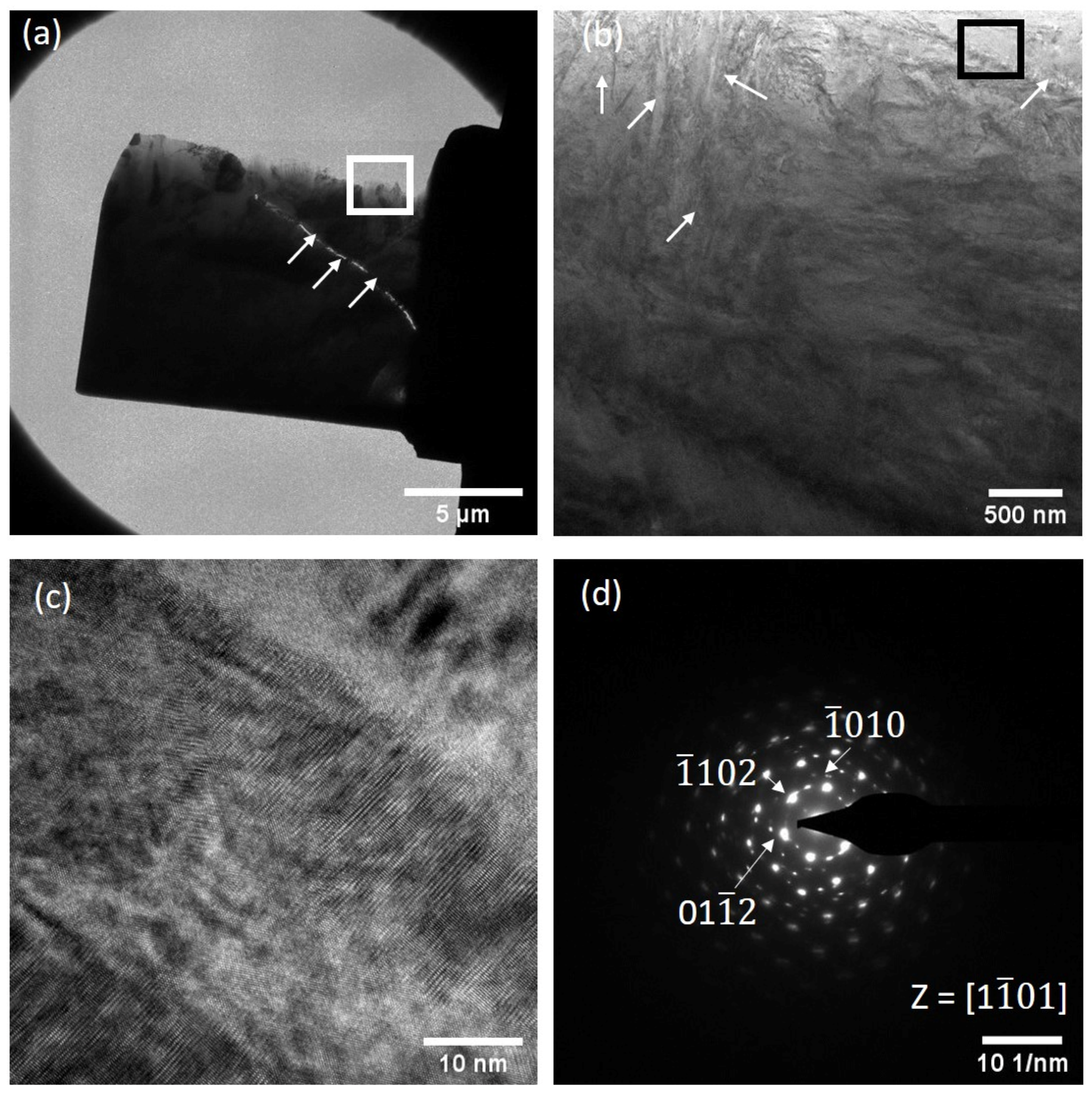
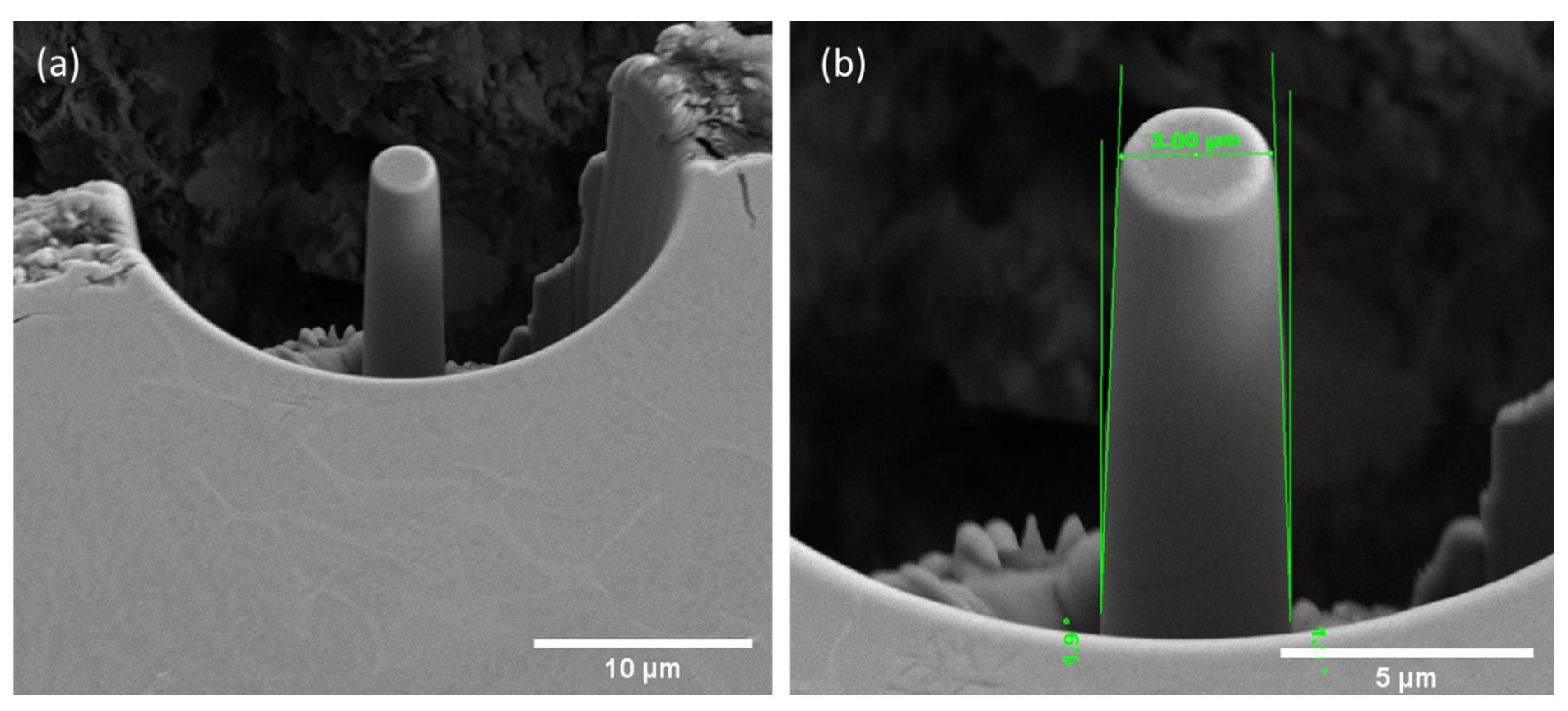
3.1. Materials Characterization and Fabrication of Micro-Pillars

The morphology of a typical machined surface on the surface of cylindrical block is presented in Figure 2 at various magnifications, together with EDS spectrum and elemental analysis (Figure 2d). The presence of globules, re-solidified debris, molten droplets, craters of different sizes and cracks on the surface is evident in Figure 2. This is the direct result of complete melt and subsequent re-solidification of molten materials due to rapid cooling in the WEDM zone. Such surface texture gives rise to relatively high surface roughness (Ra = 2.1 µm). In addition to the elements that are present in base alloy (Ti, Al and V), the machined surface also incorporates Cu and Zn (Figure 1), which can only be derived from the Zn-coated brass wire which was used as the electrode in the WEDM process. In addition, the high C content may come from the decomposition of electrolyte which is typical in the case of the WEDM process as reported by Pramanik et al. [2] on the same material, with the presence of oxygen as result of oxidation. As this surface was in direct contact with electrolyte, its cooling rate was high. Due to such rapid cooling, molten/vaporised material are vitrified and give rise to residual stresses. As stress build-up continues, it eventually exceeds the ultimate strength of the material at some point and release the stress in the form of cracks as explained by Hasçalık et al. [12] on EDM of Ti-alloy. Numerous cracks are also present in the current case as shown by arrows in Figure 2c.
Figure 3 displays a cross-sectional SEM image of a machined surface, together with EDS spectrum (Figure 3b–d) of different sub-surface layers. As is evident from Figure 3, there are two distinct layers, with the topmost layer being the recast layer with average thickness of about 10 µm. This recast layer is non-uniform with number of cracks in it. Underneath the recast layer is a slightly tempered layer, similar to those occurring in welded joints as reported by Basak et al. [27] on welded steel-joints and commonly termed the HAZ. Due to the low thermal conductivity of Ti6Al4V alloy, this zone experiences heat flux/accumulation during the WEDM process, which is higher than that experienced by the outer surface. The recast layer is the outermost layer, and it is in direct contact with the dielectric. Thus, the heat is dissipated more quickly with the flow of dielectric.
As a result, the microstructure of this HAZ is similar to that of the base Ti6Al4V alloy, however somewhat tempered in nature. The EDS spectra (Figure 3c,d) of the sub-surface HAZ and base alloy confirm that the accumulation of elements from the WEDM wire and decomposition of electrolyte are solely confined to the recast layer zone, with the composition of HAZ similar to that of base alloy. It is noteworthy that cracks in the recast layers are arrested by the presence of the HAZ. The presence of the HAZ underneath the recast layer is not universal, as Jabbaripour et al. [28] reported its existence as did Aspinwall et al. [9] albeit not on the same Ti-alloy. This apparent discrepancy may be a result of varying machining parameters used in WEDM in the relevant literatures, along with the variation in preparation of cross-sectional samples by ensuring the retention of recast layer. Underneath both the recast layer and HAZ, the base material is distinguishable by the presence of representative alpha-beta structure of Ti6Al4V alloy as explained by Pramanik et al. [5]. The microstructure of the bulk Ti6Al4V is well documented in literature as reported by Pramanik et al. [5] and therefore is not repeated here. Instead of that, focus was given on the microstructure of the recast layer which was otherwise not available in literature. To investigate the microstructure of the recast layer further, TEM sample was prepared at a location marked with a white bar in Figure 3a and the outcome is presented in Figure 4 as bright field TEM (BF-TEM) images together with a selected area electron diffraction (SAED) pattern. As the recast layer and HAZ formed all around the cylindrical block, the images in Figure 4 is representative and independent of the location from where the TEM foil was made on the cylindrical block. Presence of crack in the recast layer is also visible in TEM sample as marked with arrows in Figure 3a together with the presence of different carbide and oxide particles. The presence of these particles in recast layers was reported in literature by Hasçalık et al. [12] via an X-ray diffraction technique. Figure 4b shows the enlarger view of the marked area in Figure 4a (white box) and confirms the presence of needle like features that are somewhat resemble to martensitic like microstructure as reported in the case of Ti6Al4V alloy that were subjected to quenching in water by Andrade et al. [29] on Ti-alloy. This observation was also supported by Cao et al. [30] on the same material (Ti-alloy) system. Having said that, these needles are irregular in shape as marked with arrows in Figure 4b. A representative high-resolution TEM (HRTEM) image of one of the needles (marked with a black box in Figure 4b) is shown in Figure 4c with a corresponding SAED pattern in Figure 4d. As evident from Figure 4c, the crystallographic orientation of the martensitic needles is different to that of the matrix and are in the size range of 20–40 nm. The SAED pattern (Figure 4d) confirm the hexagonal closed packed (hcp) alpha Ti phase in the recast layer.

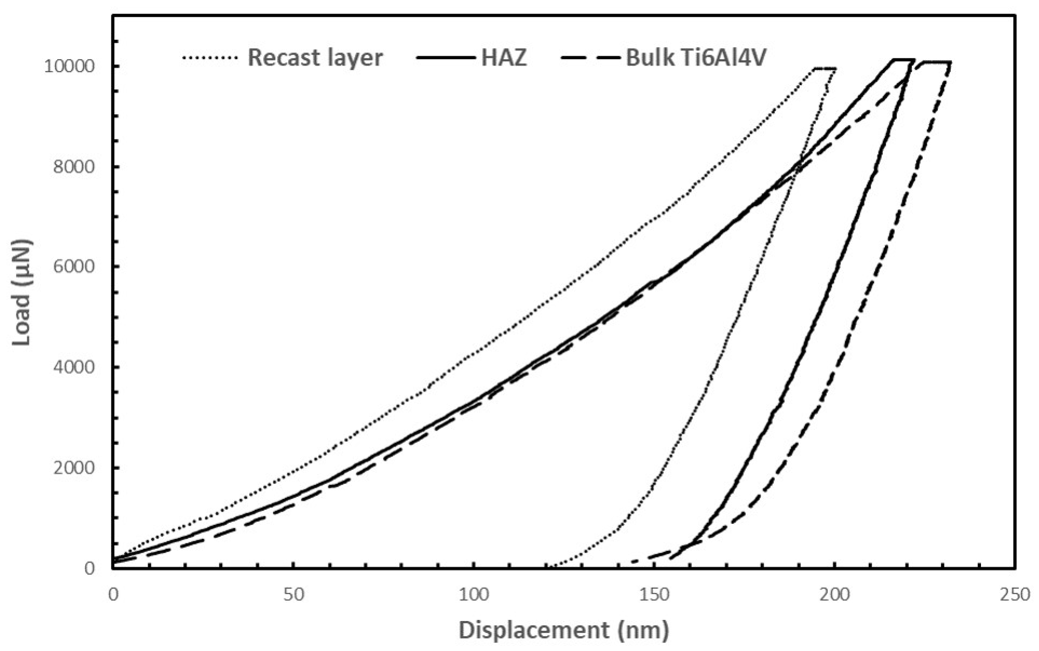
3.2. Nanoindentation

To determine the representative hardness and plastic–elastic behaviour of the different subsurface layers, nanoindentation was carried out on cross-section. The resultant representative load-displacement curves of the different layers are shown in Figure 5. All the layers experience both elastic and plastic deformation with some elastic recovery after full unloading. The unloading portion of the curves were used to calculate Young’s modulus and hardness as reported in Table 1, together with their representative elastic/plastic ratio. The elastic/plastic ratio was calculated by dividing residual displacement with recovered displacement as reported by Basak et al. [27] on cermet coatings.
The relatively high hardness of the recast layer is due the formation of various carbides (Ti24C15, TiC and Al2Ti4C2) and oxide (TiOx) particles together with martensite like microstructure as reported in Section 3.1. In addition, according to phase diagrams the microstructure of the recast layer is based on hexagonal martensitic (α′), and thus gives rise to higher hardness as reported by Misra et al. (2005) on Ti-alloy. Similar to that of the heat treatment of metals, the HAZ is slightly tempered in nature and thus its hardness (4.39 GPa) is somewhat higher than that of base alloy (3.89 GPa).

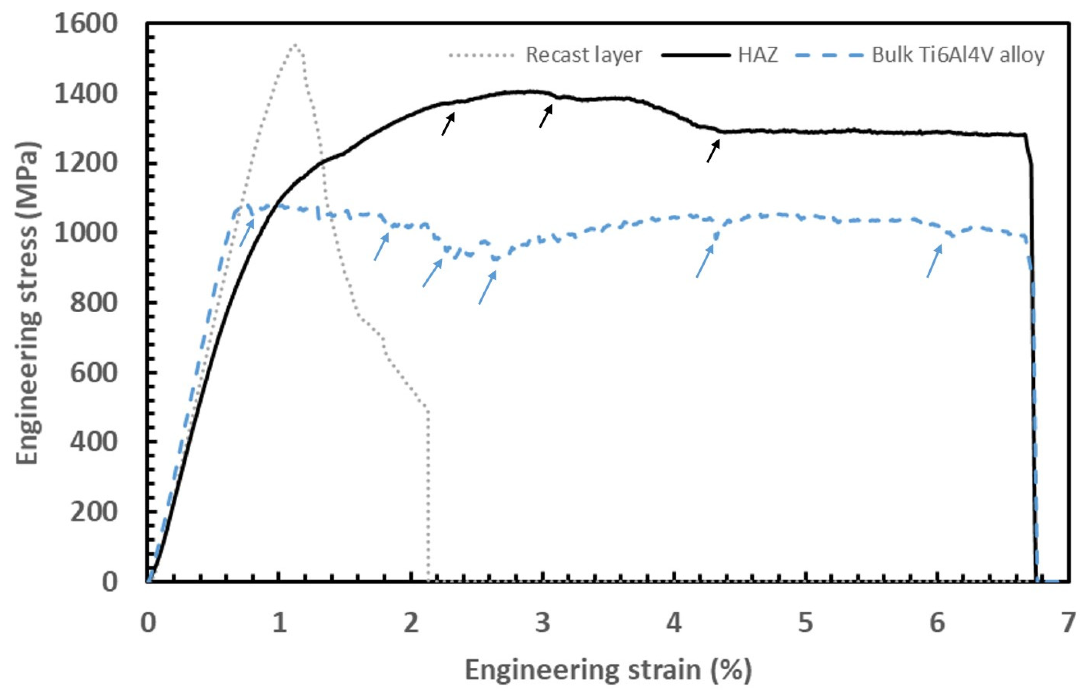
3.3. In Situ Micro-Pillar Compression

As mentioned in the experimental section, to retain sufficient gaps between the micro-pillars and surrounding materials, the micro-pillars were made in the centre of a 30 µm diameter cavity as shown in Figure 6 at different magnification. The pillars are sightly tapered (<2°) due to unavoidable ion beam-material interaction.
Stress-strain curves of the micro-pillars as converted from associated load-displacement curves, are shown in Figure 7 after compression. At first glance, this shows that the stress–strain behaviour of the recast layer is distinct from that of both the HAZ and base alloy. The recast layer appears to be able to sustain more stress than that of both the HAZ and base alloy, at the expense of being unable to incorporate strain. This is not surprising, as it is evident from the nanoindentation results that the recast layer is hard and brittle in nature compared to both the HAZ and base alloy. It was also evident from the videos recorded during the micro-pillar compression tests, as the micro-pillars on the recast layer break down (collapse) completely within less than 2% strain. In opposition to that, stress–strain curves of both the HAZ and base alloy appear to sustain considerably more strain (up to 6.8%). This gives rise to higher yield stress of the recast layer than that of the HAZ and base alloy. The base alloy shows a discrete work-hardening effect (as pointed by arrows in Figure 7) that is characteristic of metallic materials as shown by Basak et al. [24] in the case of Al-based MMCs.
Work hardening (strain bursts) in stress–strain curves is associated with the formation of shear/slip bands and associated strain/work hardening of workpiece materials. Accordingly, the relatively flat portion of the stress–strain curve after yielding is due to ongoing plastic deformation of the material in the absence of any work hardening. This was further evident by correlating the morphology of deformed pillars at different stages of deformation as shown in Figure 8. As can be seen from Figure 8a,b, the micro-pillar in the recast layer suffers collapse after around 1% strain. On the other hand, micro-pillars on both HAZ and base alloy show the development of slip bands as shown by arrows in Figure 8d–i.
The mechanical properties of sub-surface layers such as yield strength (σy), and ultimate tensile strength (σUTS) were calculated from the stress–strain curves, as tabulated in Table 2. The high yield strength stress of the recast layer is mainly due to its hard and brittle nature and inability to accommodate deformation compared to HAZ and base alloy.

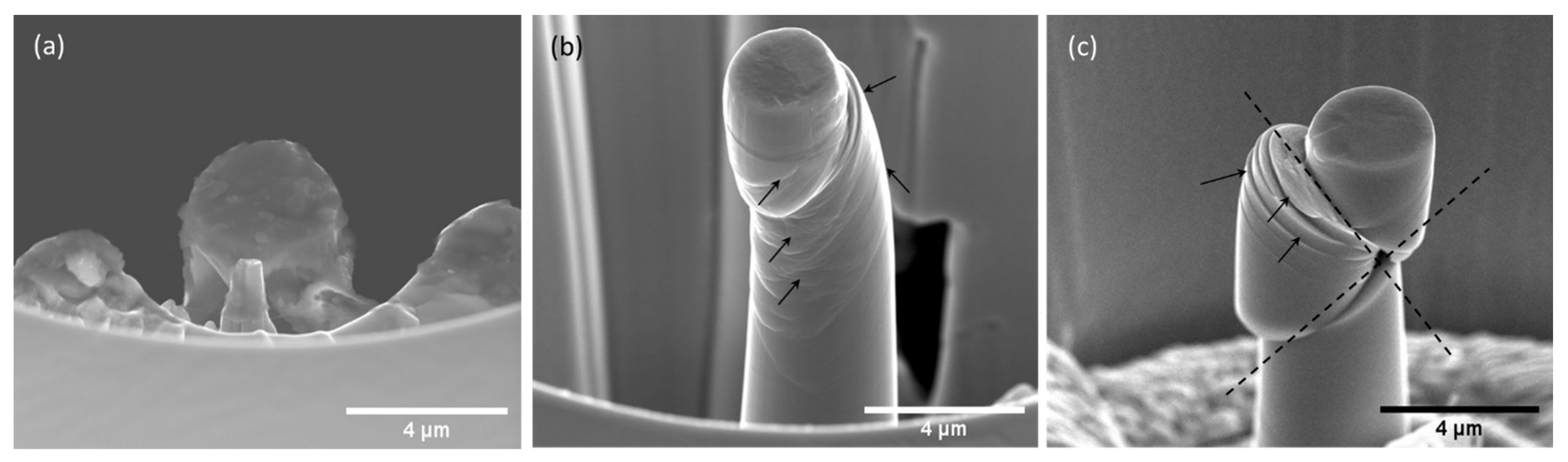
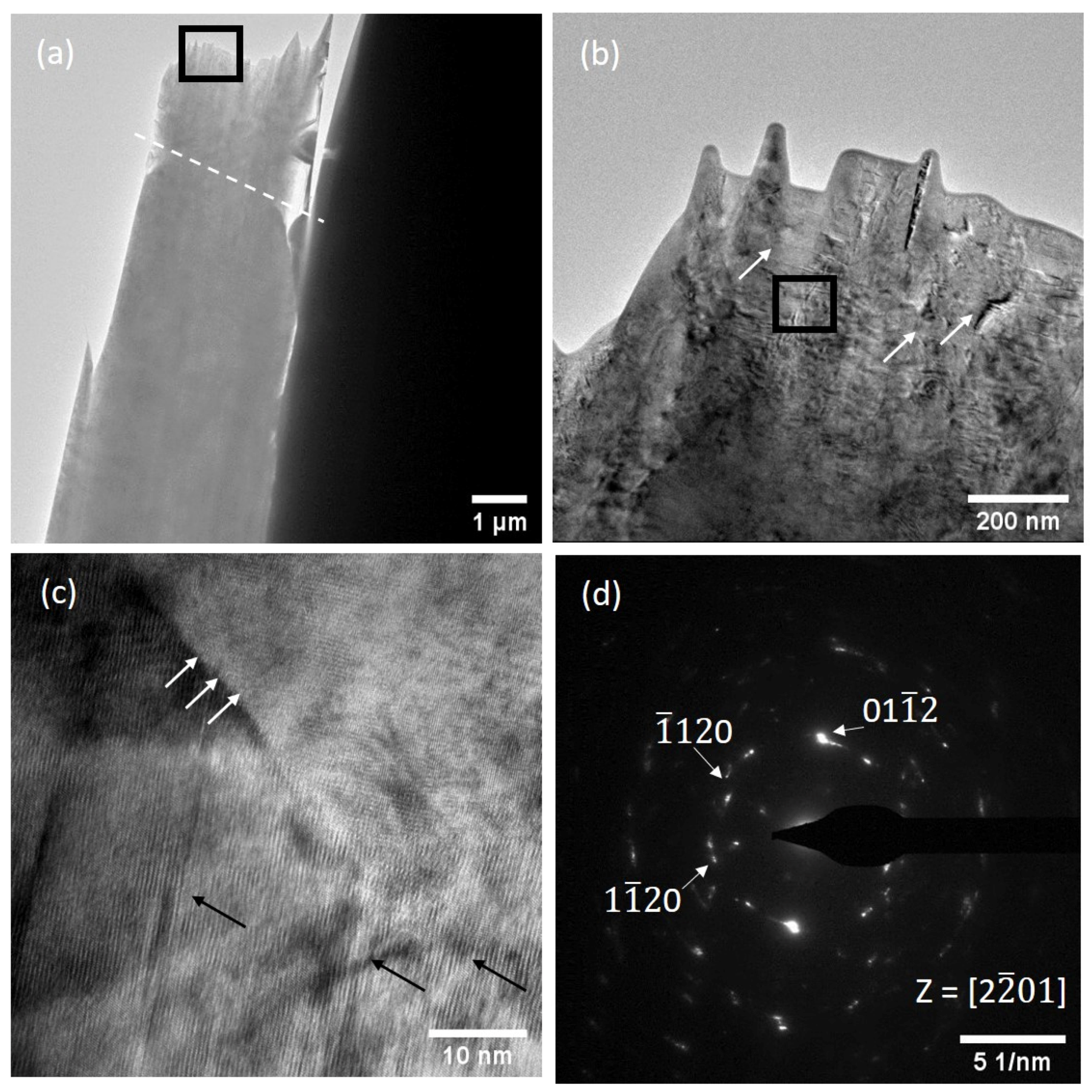
3.4. Analysis of Deformed Micro-Pillars

After compression tests, the morphology of the deformed micro-pillars was investigated via SEM. Representative images are shown in Figure 9 and the complete magnitude of deformation is apparent. A number of slip/shear bands were evident as shown by arrows on the HAZ and base material. Qualitatively, the density of slip/shear bands on HAZ is more than that of the base material. Deformed micro-pillars include a huge network of slip/shear bands that bisects with each other (dotted lines). The steps along slip/shear bands are physical proof of work hardening as indicated in engineering stress–strain curves. Full fracture (physical split) through a micro-pillar diameter took place at approximately 45°.
To investigate the nature of slip/shear planes further, TEM samples were prepared on deformed micro-pillars. As the micro-pillars in the recast layer collapsed during compression, it was not possible to prepare TEM samples from them. Figure 10a shows the TEM image of the whole deformed pillar in the HAZ region with the presence of slip line as marked with dashed line. An enlarged view of the selected area of Figure 10a (marked with black box) is shown in Figure 10b and exhibits extensive deformation in terms of slip/shear lines, dislocations and stacking faults. HRTEM image (Figure 10c) of the selected area of Figure 10b (marked with black box) shows the presence of twins (marked with white arrows) as well as the presence of stacking faults (marked with black arrows). Figure 10d shows the corresponding SAED patterns that demonstrate the polycrystalline nature of the material and the streaks in the SAED pattern confirm the presences of multiple stacking faults.
Figure 11 shows the TEM images of deformed micropillars on base Ti6Al4V with a representative BF-TEM image (Figure 11a,b), HRTEM image (Figure 11c) and corresponding SAED pattern (Figure 11d). Due to extensive deformation, physical separation across the micro-pillar diameter is evident in Figure 11a, as marked with arrow. This physical separation corresponds to the slip planes as shown in Figure 9c. A vast array of dislocations, slip/share bands and stacking faults are evident in Figure 11b and marked with arrows. The HRTEM image (Figure 11c) across one of the slip/shear band shows the presence of high-density stacking faults which form in response of load accommodation mechanism during deformation. The SAED pattern (Figure 11d) across this region shows the crystal structure which is more resemble to the rhombohedral rather than hexagonal close pack (hcp) structure of the Ti6Al4V alloy. This is supported by the fact that <1011> and <1122> deformation twins more favourable to occur during compression as outlines in literature by Christian et al. [31] on deformation twinning of the Ti-alloy and by Zaeffere et al. [32] on the texture of the Ti-alloy.

3.5. Mechanism of Deformation and Strengthening

As is obvious from stress–strain curves (Figure 7), there are number of short strains burst as pointed out by arrows. In monolithic metal and alloys, strain bursts represent a work-hardening feature of the materials. Under external loading (for example, compression in this case), the combination of stacking faults and dislocations attempt to compensate for the loading by means of crystal structure/orientation rearranging. This provides a brief strength increase of the material in question. With the increase of applied load, this rearranging repeats until the work-hardening effect caught in short on materials strength. At that point, the material is incapable of absorbing any further loading. Subsequently, a new mechanism takes place to absorb further loading in the form of slip line/plane due to shear. This is apparent from the existence of slip lines/planes on the surface of pillars (Figure 8 and Figure 9). These slip lines/planes have a characteristic ‘stair-case’ like exterior and are distinct in nature. Unlike the base alloy, work hardening is less prominent in the HAZ. This is most likely due to the slight heat treatment property of the layer that took place during WEDM. As such, most of the dislocations and stacking faults (defects, in general) were annihilated. Thus, yield strength of the HAZ is higher than that of monolithic base alloy, and as a result, plastic deformation of the HAZ material took place in the form of slip bands. During compressive loading, compressive shear bands with buckling (barrelling effect) are expected due to improper selection of the aspect ratio of the micro-pillars, as reported by Misra et al. [26] on micro-pillar compression. However, in this case buckling was avoided (Figure 8 and Figure 9), making the deformation mechanism straightforward, owing to the proper selection of aspect ratios. Micro-pillars on the base alloy exhibited a relatively larger size of slip steps, and a number of slip planes that are parallel to each other. Conversely, deformed pillars on HAZ material showed a relatively larger number of slip steps that were kinked in nature (Figure 9b). As suggested by the deformation mechanism of materials, initiation and formation of voids is correlated with such ductile failure, where localized stress is insufficient to initiate any crack formation as reported by Srivatsan et al. [33] on deformation of 6061 Al-alloy composite, by Uchic et al. [34] on plasticity of single crystal compression, and by Zhang et al. [35,36] on compression of Cu-Zr micro-pillars. The deformation mechanisms described above can be reviewed through the following steps:
(1)
Recast layer: hard and brittle in nature, and thus cannot accommodate any strain exceeding about 1%.
(2)
HAZ: due to its heat-treated nature, most of the dislocations, stacking faults, and defects in general were annihilated. Thus, deformation took place mostly by the formation of slip bands.
(3)
Base Ti6Al4V alloy: rearranging of crystal structure and orientation by movement of stacking faults and dislocations. Following this, plastic flow of the material along preferred slip/shear planes by formation of micro-voids.
Although the micro-pillar compression is a unique technique and provides valuable insight on deformation mechanisms of materials, it should be practiced with caution. There are several factors that have to be taken into account that could affect reproducibility, one being the homogeneity of the material. Another crucial point is the size effect which can be both external and internal. External size effect is the response of the pillar diameter upon loading, whereas internal size effect refers to the grain size of the materials. Although these are important factors to consider, these are outside the scope of the present paper and require further research.

4. Conclusions

Compression of micro-pillar under in situ conditions on different sub-surface layers of WEDM-processed Ti6Al4V alloy was performed together with the monolithic base alloy. Based on reported experimental evidence and subsequent discussions, the following conclusions can be drawn:
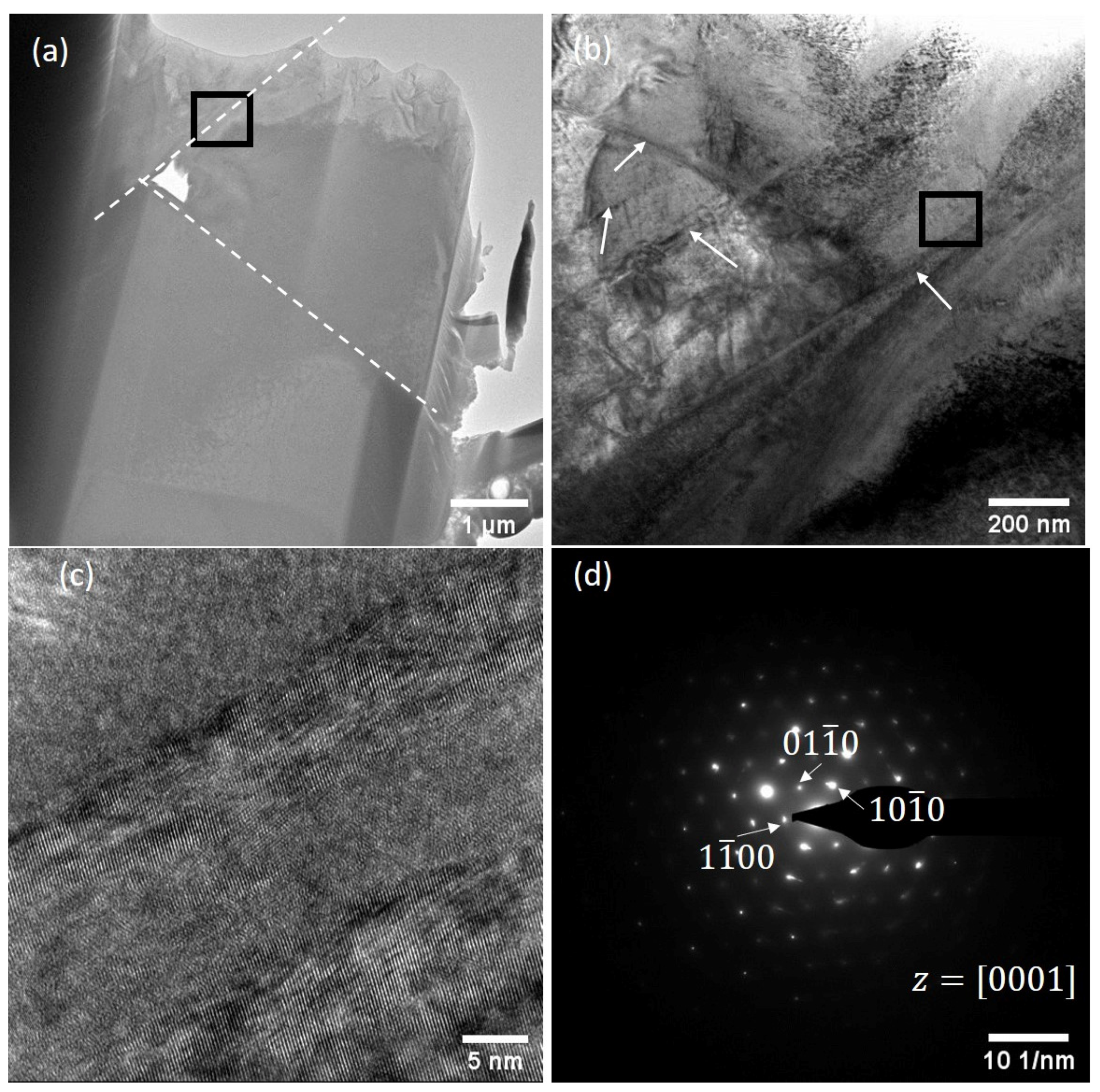
  • The recast layer shows martensitic (a mixture of alpha’ and alpha’’ phases)-like microstructure together with the presence of sub-surface cracks, and different carbide and oxide particles.
  • The recast layer exhibits higher hardness, elastic modulus, and lower plastic to elastic ratio than that of HAZ and bulk material. This observation was further supported by higher yield stress of the recast layer within limited strain level (within 1%) during micro-pillar compression.
  • The substantial strength increase of the HAZ is a collective result of the following effects: annihilation of defects that took place during WEDM processing; strengthening of slip/shear plane due to the absence of any defects that enhance load bearing capacity.
  • The base material exhibits the traditional deformation mechanisms of other metallic alloys, namely preliminary absorption of applied load by formation of a slip/shear band followed by extended plastic deformation. Final fracture of the pillars took place along the weakest crystal planes because of maximum shear stress experience.

Author Contributions

Conceptualization and analysis, A.B.; Experiments and edit, A.P.: Review and edit, C.P., S.S. and S.D. All authors have read and agreed to the published version of the manuscript.

Funding

This research received no external funding.

Institutional Review Board Statement

Not applicable.

Informed Consent Statement

Not applicable.

Data Availability Statement

Not applicable.

Conflicts of Interest

The authors declare that they have no known competing financial interests or personal relationships that could have appeared to influence the work reported in this paper.

References

  1. Roy, A.; Narendranath, S.; Pramanik, A. Effect of peak current and peak voltage on machined surface morphology during WEDM of TiNiCu shape memory alloys. J. Mech. Sci. Technol. 2020, 34, 3957–3961. [Google Scholar] [CrossRef]
  2. Pramanik, A.; Basak, A.K.; Prakash, C.; Shankar, S.; Sharma, S.; Narendranath, S. Recast Layer Formation during Wire Electrical Discharge Machining of Titanium (Ti-Al6-V4) Alloy. J. Mater. Eng. Perform. 2021, 30, 8926–8935. [Google Scholar] [CrossRef]
  3. Pramanik, A.; Basak, A.K.; Dixit, A.R.; Chattopadhyaya, S. Processing of duplex stainless steel by WEDM. Mater. Manuf. Process. 2018, 33, 1559–1567. [Google Scholar] [CrossRef] [Green Version]
  4. Mohanty, A.; Talla, G.; Gangopadhyay, S. Experimental Investigation and Analysis of EDM Characteristics of Inconel 825. Mater. Manuf. Process. 2014, 29, 540–549. [Google Scholar] [CrossRef]
  5. Pramanik, A.; Basak, A. Effect of wire electric discharge machining (EDM) parameters on fatigue life of Ti-6Al-4V alloy. Int. J. Fatigue 2019, 128, 105186. [Google Scholar] [CrossRef]
  6. Pramanik, A.; Basak, A.K.; Littlefair, G.; Debnath, S.; Prakash, C.; Singh, M.A.; Singh, R.K. Methods and variables in Electrical discharge machining of titanium alloy—A review. Heliyon 2020, 6, e05554. [Google Scholar] [CrossRef] [PubMed]
  7. Azam, M.; Jahanzaib, M.; Abbasi, J.A.; Abbas, M.; Wasim, A.; Hussain, S. Parametric analysis of recast layer for-mation in wire-cut EDM of HSLA steel. Int. J. Adv. Manuf. Technol. 2016, 87, 713–722. [Google Scholar] [CrossRef]
  8. Zhenlong, W.; Xuesong, G.; Guanxin, C.; Yukui, W. Surface Integrity Associated with SiC/Al Particulate Composite by Micro-Wire Electrical Discharge Machining. Mater. Manuf. Process. 2014, 29, 532–539. [Google Scholar] [CrossRef]
  9. Aspinwall, D.; Soo, S.; Berrisford, A.; Walder, G. Workpiece surface roughness and integrity after WEDM of Ti–6Al–4V and Inconel 718 using minimum damage generator technology. CIRP Ann. 2008, 57, 187–190. [Google Scholar] [CrossRef]
  10. Newton, T.R.; Melkote, S.N.; Watkins, T.; Trejo, R.M.; Reister, L. Investigation of the effect of process parameters on the formation and characteristics of recast layer in wire-EDM of Inconel 718. Mater. Sci. Eng. A 2009, 513-514, 208–215. [Google Scholar] [CrossRef]
  11. Mouralova, K.; Kovar, J.; Klakurkova, L.; Blazik, P.; Kalivoda, M.; Kousal, P. Analysis of surface and subsurface layers after WEDM for Ti-6Al-4V with heat treatment. Measurement 2018, 116, 556–564. [Google Scholar] [CrossRef]
  12. Hasçalık, A.; Çaydaş, U. Electrical discharge machining of titanium alloy (Ti-6Al-4V). Appl. Sur. Sci. 2007, 253, 9007–9016. [Google Scholar] [CrossRef]
  13. Basak, A.; Pramanik, A.; Prakash, C.; Kotecha, K. Micro-mechanical characterization of superficial layer synthe-sized by electric discharge machining process. Mater. Lett. 2021, 305, 130769. [Google Scholar] [CrossRef]
  14. Novich, B.E.; Adams, R.W.; Fennessy, K.P. Metal matrix composites for single chip and multichip microprocessor packaging. In Proceedings of the 1995 International Electronics Packaging Conference, San Diego, CA, USA, 24–27 September 1995. [Google Scholar]
  15. Risegari, L.; Barucci, M.; Lolli, L.; Ventura, G. Low Temperature Thermal Conductivity of Ti6Al4V Alloy. J. Low Temp. Phys. 2008, 151, 645–649. [Google Scholar] [CrossRef]
  16. Sweet, J.N.; Roth, E.P.; Moss, M. Thermal conductivity of Inconel 718 and 304 stainless steel. Int. J. Thermophys. 1987, 8, 593–606. [Google Scholar] [CrossRef]
  17. Xu, B.; Lian, M.-Q.; Chen, S.-G.; Lei, J.-G.; Wu, X.-Y.; Guo, C.; Peng, T.-J.; Yang, J.; Luo, F.; Zhao, H. Combining PMEDM with the tool electrode sloshing to reduce recast layer of titanium alloy generated from EDM. Int. J. Adv. Manuf. Technol. 2021, 117, 1535–1545. [Google Scholar] [CrossRef]
  18. Holmberg, J.; Wretland, A.; Berglund, J. Grit Blasting for Removal of Recast Layer from EDM Process on Inconel 718 Shaft: An Evaluation of Surface Integrity. J. Mater. Eng. Perform. 2016, 25, 5540–5550. [Google Scholar] [CrossRef] [Green Version]
  19. Qua, J.; Shih, A.J.; Scattergood, R.O.; Luo, J. Abrasive micro-blasting to improve surface integrity of electrical dis-charge machined WC–Co composite. J. Mater. Process. Technol. 2005, 166, 440–448. [Google Scholar] [CrossRef]
  20. Wang, C.-C.; Chow, H.-M.; Yang, L.-D.; Luc, C.-T. Recast layer removal after electrical discharge machining via Taguchi analysis: A feasibility study. J. Mater. Process. Technol. 2009, 209, 4134–4140. [Google Scholar] [CrossRef]
  21. Khangura, S.S.; Sran, L.S.; Srivastava, A.K.; Singh, H. Investigations into the removal of EDM recast layer with magnetic abrasive machining. In International Manufacturing Science and Engineering Conference; American Society of Mechanical Engineers: New York, NY, USA, 2015; ISBN 978-0-7918-5682-6. [Google Scholar]
  22. Mouralova, K.; Zahradnicek, R.; Benes, L.; Prokes, T.; Hrdy, R.; Fries, J. Study of Micro Structural Material Changes after WEDM Based on TEM Lamella Analysis. Metals 2020, 10, 949. [Google Scholar] [CrossRef]
  23. Kurdi, A.; Basak, A.K. Deformation of electrodeposited gradient Co/Sn multilayered coatings under micro-pillar com-pression. Eng. Frac. Mech. 2018, 204, 138–146. [Google Scholar] [CrossRef]
  24. Basak, A.; Pramanik, A.; Prakash, C. Deformation and strengthening of SiC reinforced Al-MMCs during in-situ micro-pillar compression. Mater. Sci. Eng. A 2019, 763, 138–141. [Google Scholar] [CrossRef]
  25. Basak, A.K.; Zhang, L. Deformation of Ti-Based Bulk Metallic Glass Under a Cutting Tip. Tribol. Lett. 2018, 66, 27. [Google Scholar] [CrossRef]
  26. Misra, A.; Hirth, J.P.; Hoagland, R.G. Length-scale-dependent deformation mechanisms in incoherent metallic multi-layered composites. Acta Mater. 2005, 53, 4817–4824. [Google Scholar] [CrossRef]
  27. Basak, A.; Achanta, S.; Celis, J.-P.; Vardavoulias, M.; Matteazzi, P. Structure and mechanical properties of plasma sprayed nanostructured alumina and FeCuAl–alumina cermet coatings. Surf. Coat. Technol. 2008, 202, 2368–2373. [Google Scholar] [CrossRef]
  28. Jabbaripour, B.; Sadeghi, M.H.; Faridvand, S.; Shabgard, M.R. Investigating the Effects of Edm Parameters on Surface Integrity, Mrr and Twr in Machining of Ti–6Al–4V. Mach. Sci. Technol. 2012, 16, 419–444. [Google Scholar] [CrossRef]
  29. Andrade, A.; Morcelli, A.; Lobo, R. Deformation and fracture of an alpha/beta titanium alloy. Rev. Matéria 2010, 15, 364–370. [Google Scholar] [CrossRef] [Green Version]
  30. Cao, S.; Chu, R.; Zhou, X.; Yang, K.; Jia, Q.; Lim, C.V.S.; Huang, A.; Wu, X. Role of martensite decomposition in tensile properties of selective laser melted Ti-6Al-4V. J. Alloy. Comp. 2018, 744, 357–363. [Google Scholar] [CrossRef]
  31. Christian, J.W.; Mahajan, S. Deformation twinning. Process. Mater. Sci. 1995, 39, 1–157. [Google Scholar] [CrossRef]
  32. Zaefferer, S. A study of active deformation systems in titanium alloys: Dependence on alloy composition and correla-tion with deformation texture. Mater. Sci. Eng. A 2003, 344, 20–30. [Google Scholar] [CrossRef]
  33. Srivatsan, T.; Al-Hajri, M.; Petraroli, M.; Hotton, B.; Lam, P. Influence of silicon carbide particulate reinforcement on quasi static and cyclic fatigue fracture behaviour of 6061 aluminium alloy composites. Mater. Sci. Eng. A 2002, 325, 202–214. [Google Scholar] [CrossRef]
  34. Uchic, M.D.; Shade, P.A.; Dimiduk, D.M. Plasticity of Micrometer-Scale Single Crystals in Compression. Annu. Rev. Mater. Sci. 2009, 39, 361–386. [Google Scholar] [CrossRef] [Green Version]
  35. Zhang, J.; Liu, G.; Lei, S.; Niu, J.; Sun, J. Transition from homogeneous-like to shear-band deformation in nanolayered crystalline Cu/amorphous Cu–Zr micropillars: Intrinsic vs. extrinsic size effect. Acta Mater. 2012, 60, 7183–7196. [Google Scholar] [CrossRef]
  36. Basak, A.; Diomidis, N.; Celis, J.-P.; Masquelier, C.; Warichet, D. Chemical reactivity of thermo-hardenable steel weld joints investigated by electrochemical impedance spectroscopy. Electrochim. Acta 2008, 53, 7575–7582. [Google Scholar] [CrossRef]
Figure 1. Photograph of the cylindrical block cut from the workpiece by the wire electro-discharge machining (WEDM) process and location of different sub-surface layers (overlayed).
Metals 12 00188 g001
Figure 2. Representative features on a machined surface after WEDM at various magnifications on cylindrical blocks (ac) together with energy-dispersive X-ray spectroscopy (EDX) spectra and elemental composition (d). The EDX was taken as point analysis in the recast layer at the tip of the arrows given in (c).
Metals 12 00188 g002
Figure 3. Typical cross-sectional view (a) together with respective EDX spectra and elemental composition of (b) re-cast layer, (c) heat-affected zone (HAZ) and (d) base Ti6Al4V alloy after metallographic polishing of the sample. The EDX was taken as the point analysis in recast layer at the tip of the arrows given in (a).
Metals 12 00188 g003
Figure 4. Representative transmission electron microscopy (TEM) images of the recast layer: (a) bright-field (BF)-TEM image showing the presence of crack; (b) enlarged view of the marked area in Figure 4a; (c) high-resolution (HR) TEM image of marked area in Figure 4b and (d) corresponding selected area electron diffraction (SAED) pattern.
Metals 12 00188 g004
Figure 5. Typical load–displacement curves on recast layer, HAZ and base Ti6Al4V alloy.
Metals 12 00188 g005
Figure 6. Representative micro-pillar in the middle of Ø 30 µm pit of the recast layer (a) together with dimension on high magnification images in (b).
Metals 12 00188 g006
Figure 7. Stress-strain curves on recast layer, HAZ and base Ti6Al4V alloy obtained from in situ micro-pillar compression. Arrows indicate work hardening effects as discussed in text.
Metals 12 00188 g007
Figure 8. State of micro-pillars at different strain interval in course of compression: (ac) recast layer, (df) HAZ and (gi) base Ti6Al4V alloy.
Metals 12 00188 g008
Figure 9. Scanning electron microscopy (SEM) view of micro-pillars after deformation as a result of compression: (a) Recast layer (remaining of the pillar after collapse), (b) HAZ and (c) base Ti6Al4V alloy.
Metals 12 00188 g009
Figure 10. Representative TEM images of deformed micro-pillar on HAZ region: (a) BF-TEM image of deformed pillar; (b) enlarged view of the selected area as marked in Figure 10a; (c) HRTEM image on region indicated in Figure 10b and (d) corresponding SAED pattern.
Metals 12 00188 g010
Figure 11. Representative TEM images of deformed micro-pillar on Ti6Al4V base alloy: (a) BF-TEM image of deformed pillar; (b) enlarged view of the selected area as marked in Figure 10a; (c) HRTEM image on region indicated in Figure 10b and (d) corresponding SAED pattern.
Metals 12 00188 g011
Table 1. Mechanical properties of the different layers calculated from load–displacement curves.
MaterialHardness (H), GPaElastic Modulus (Er), GPaPlastic to Elastic Ratio
Recast layer 5.05 ± 0.04125.33 ± 3.511.33
HAZ4.39 ± 0.12122.52 ± 2.292.05
Base Ti6Al4V alloy3.89 ± 0.04123.41 ± 2.012.32
Table 2. Mechanical properties of recast layer, HAZ and base alloy calculated from stress–strain curves.
MaterialYield Strength (σy),
MPa
Ultimate Tensile Strength (σUTS), MPa
Recast layer 1520 ± 2431520 ± 253
HAZ1170 ± 1541401 ± 135
Base Ti6Al4V alloy1019 ± 1261069 ± 145
Publisher’s Note: MDPI stays neutral with regard to jurisdictional claims in published maps and institutional affiliations.

