Article

Numerical Analysis of Electron Beam Welding Deformation for the Vacuum Vessel Lower Port Stub of 316L Stainless Steel

1
College of Physics and Optoelectronic Engineering, Shenzhen University, Shenzhen 518060, China
2
Institute of Plasma Physics, Hefei Institutes of Physical Science, Chinese Academy of Sciences, Hefei 230031, China
3
Anhui Province Key Laboratory of Special Welding Technology, Huainan 232000, China
4
Advanced Energy Research Center, Shenzhen University, Shenzhen 518060, China
*
Author to whom correspondence should be addressed.
Metals 2022, 12(2), 224; https://doi.org/10.3390/met12020224
Submission received: 9 December 2021 / Revised: 30 December 2021 / Accepted: 21 January 2022 / Published: 25 January 2022

Abstract

:
The China Fusion Engineering Test Reactor vacuum vessel has strict tolerances requirements and a large number of fully penetrated joints in the manufacturing and assembly processes. As the most complicated component of vacuum vessel, port stubs have stricter tolerance requirements, to guarantee the high assembly accuracy with the vacuum vessel. Due to the small deformation of electron beam welding, this method is adopted for the welding of port stub. However, welding deformation cannot be avoided, thus it is necessary to carry out finite element analysis to analyze and control the welding deformation of the port stub. In this paper, based on thermo-elastic–plastic theory, the double ellipsoid and cone-shaped hybrid heat source can accurately outline the electron beam weld pool contour of the 316L stainless steel with 50 mm thickness, which is further verified by the welding process experiment. The above hybrid heat source is applied to analyze the welding deformation of the lower port stub, and according to the deformation simulation results, the welding fixture is designed to reduce the welding deformation. The welding deformation analysis can effectively provide theoretical data support and practical guidance for the actual electron beam welding process of port stub.

1. Introduction

As the next-generation fusion device in China, the China Fusion Engineering Test Reactor (CFETR) is a large-scale test platform that bridges the Fusion Demonstration Reactor (DEMO) with the International Thermonuclear Experimental Reactor (ITER) [1]. The CFETR vacuum vessel (VV) ports provide access to the plasma chamber for remote handling, heating, diagnosis, and the maintenance and replacement of the in-vessel components [2]. The ports are attached to port stubs, which are integral to the inner and outer shells of the main vessel, as shown in Figure 1. As the safety important class (SIC) components, all welds of the VV must be fully penetrated [3]. However, the VV has extremely high manufacturing tolerance requirements, and the port stub as its sub-component has stricter tolerance requirements [4]. The port stub has complex three-dimensional features, and there are many fully penetrated joints. In order to control its dimensional accuracy, electron beam (EB) welding is used because of its low heat input, small welding heat affected zone, and small deformation [5]. However, welding deformation always exists; to further control the deformation, it is necessary to predict the deformation and design corresponding fixtures to reduce the deformation.
The digital simulation of welding deformation is a focus in the field of engineering applications. The digital simulation can quickly design and optimize welding processes and structures, evaluate post-welding quality, and reduce trial/error costs. At present, the finite element method based on the thermo-elastic–plastic theory is mainly adopted to predict welding deformation, optimize welding process parameters, sequences, and fixtures [6,7,8]. This method has advantages on high calculation accuracy, and its calculation time is also acceptable with the improvement of computer abilities. Different from the traditional fusion welding, the EB welding is characterized by its high local energy concentration, instantaneous, and keyhole effect, which is prone to produce an uneven temperature field with a large gradient. The temperature field is the basis of welding deformation analysis, and the establishment of an appropriate heat source model is the premise of temperature field analysis [9,10]. Therefore, it is necessary to select an appropriate heat source to simulate the process of EB welding.
In this paper, the lower port stub of the vacuum vessel is taken as the research object, the thermo-elastic–plastic theory is adopted, and combined with the EB welding experiment. Through the heat source check function of SYSWELD software, the simulated heat source of 316L stainless steel with 50 mm thickness is determined. Then, the determined heat source is applied to the welding simulation of the lower port stub, and finally the corresponding fixtures are designed for reducing the deformation of the lower port stub on the basis of the deformation results.

2. Welding Heat Source

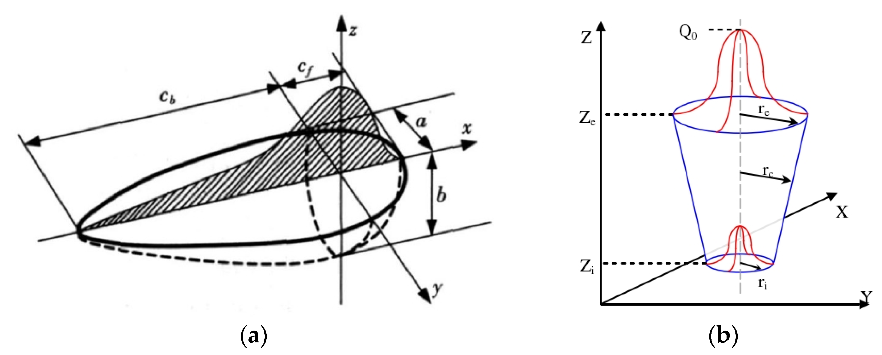
2.1. Heat Source Model

The contour of the weld pool generated by the cone-shaped heat source is spike-shaped, which is inconsistent with the EB weld of the thick plates [11]. This is because the cone-shaped heat source model is a superposition of countless Gaussian heat sources in the depth of the weld. By changing the size of each Gaussian heat source, the keyhole effect of the EB welding is simulated, but the nearly semicircular weld pool formed by the heat conduction of the molten metal discharged from the keyhole to the substrate around the weld is ignored. The double ellipsoidal heat source model can successfully simulate the semicircular weld pool formed by the heat conduction [12]. Therefore, the double ellipsoid and cone-shaped hybrid heat source model is used for the EB welding analysis of thick plates [13]. The geometric model of the heat source is shown in Figure 2.
The formulas in the hybrid heat source model calculation are shown as follows:
Q R = μ ( Q R 1 + Q R 2 ) + ( 1 μ ) Q R 3
Q R 1 = Q f · e 3 x 2 c f 2 · e 3 y 2 a 2 · e 3 z 2 b 2
Q R 2 = Q b · e 3 x 2 c b 2 · e 3 y 2 a 2 · e 3 z 2 b 2
Q R 3 = Q 0 · e 3 r 2 r c 2
r c = r i + ( r e r i ) z z i z e z i
where Q R 1 is the front hemisphere power density of the double ellipsoid heat source, Q f is the heat input of the front hemisphere, Q R 2 is the rear hemisphere power density of the double ellipsoid heat source, Q b is the heat input of the rear hemisphere, Q R 3 is the power density of the cone-shaped heat source, Q 0 is the heat input of the cone-shaped heat source, a , b , c f , c b , z e , z i , r e , r i are the parameters of the heat source, and μ is the distribution coefficient of the power density. Generally, μ takes a value between 0.1 and 0.2.

2.2. Finite Element Model

The 316L stainless steel flat plate with a size of 300 mm × 150 mm × 50 mm was taken as the finite element analysis object [16]. The welding joint was butt joint without grooves. The EB welding was adopted. The welding voltage was set to 150 kV, the beam current was set to 95 mA, the welding speed was set to 5 mm/s, and the working distance was set to 300 mm. These welding parameters have passed the qualification. The initial temperature of the flat plate was set to 20 °C, the thermal radiation loss was calculated using the Stephen–Boltzmann equation, and the surface radiation efficiency was taken as 0.8. Since EB welding was carried out in a vacuum, the convection loss was 0 W/m2. Figure 3 shows the finite element model.

2.3. Verification of the Hybrid Heat Source

Using the above welding process parameters, an EB welding experiment was carried out on the flat plate with the same size. The sample of the welded joint was prepared by electrolytical etching with oxalic acid aqueous solution at a voltage of 5 V. In this paper, the heat source check function of the SYSWELD software is used to extract the temperature cloud diagram of the weld pool, which is compared with the actual weld pool morphology. Through repeated iterative correction by the software, the results equivalent to the actual weld pool morphology are obtained, as shown in Figure 4. The bar on the left side of Figure 4 is a cross-section of the actual weld pool morphology obtained from the experiment, and the figure on the right side is a temperature cloud diagram of the simulated weld pool morphology after the heat source verification. The pink area is the area exceeding the melting point of 316L stainless steel, which is the melting zone. Compared with the actual weld pool, the simulated results have a very high degree of matching. The hybrid heat source model of EB welding was checked to ensure the calculation accuracy of the welding simulation, which lays a foundation for the application of the hybrid heat source in the calculation of the lower port stub.

3. Simulation of the Lower Port Stub

3.1. Calculation Model

According to the preliminary design of the lower port stub, the lower port stub shown on the left side of Figure 5 is composed of 14 parts and is welded by EB. In order to meet the assembly accuracy requirements of EB welding, the subsequent assembly surface need to be machined after each EB welding. The type ZD150-60C vacuum EB welding system with the size of 66 m3 vacuum vessel is used for the welding of the lower port stub. The size of the lower port stub is 2.66 m × 2.48 m × 0.95 m, due to the limitation of the position of the electron gun and the size of the vacuum vessel, the weld sequence of the A6 can only be the last. Comprehensively considering the EB welding and machining, the welds of A1, A3, A5, A7, A9, A10, A11, and A13 are all welded separately, and then the welds of A2 and A4 and A8 and A12, shown on the right side of Figure 5, are welded. Although all welds are welded by EB, there are 13 welds with a total length of 11.4 m, which will inevitably produce large deformation. Therefore, it is necessary to analyze the welding deformation and design the welding fixtures to control the deformation.
Figure 6 shows the mesh models of the EB welding deformation analysis. All meshes are the hexahedron elements. The red dots in Figure 6 are the necessary constraints imposed to prevent the workpieces from spatial displacement. Since the machining needs to be carried out after each EB welding, and the structure of each weld is different, a separate analysis model is established for each weld. The analysis method is based on the thermo-elastic–plastic theory, and the loaded heat source is the hybrid heat source. All analyses were carried out by using SYSWELD software.

3.2. Welding Deformation Analysis

Figure 7 shows the deformation cloud diagrams of A5, A8 and A12, and A6, with an amplification of 20 times, and the model in gray color is the undeformed model. As can be seen in Figure 7, except for the large deformation formed by the accumulation of the molten metal in the weld, the whole workpiece produces large angular deformation. Table 1 shows the maximum deformation of the workpiece after each weld is welded. The accumulation of deformation will inevitably cause the workpiece to be out of tolerance, and the deformation of the earlier components will cause the assembly accuracy of the subsequent components to fail to meet the requirements of EB welding. Therefore, it is necessary to design fixtures to reduce the welding deformation, and the welding deformation can be corrected by the fixtures to ensure that the assembly accuracy of the component meets the requirement of EB welding.
Based on the above analysis of the welding deformation, a set of combined welding fixtures is designed, as shown in Figure 8. The fixtures used for the welds of A1 and A5 can be used in combination and used for welding A2 and A4. The fixtures used for the welds of A7 and A13 can be used in combination and used for welding A8 and A12. These four fixtures can be combined for welding A6. Since the welds of A3 and A9, A10 and A11 are all welds of spin welding, the welding fixtures are designed separately.
The positions of the workpieces clamped by the fixtures are converted into the fixed constraints, and then the deformation of each weld is analyzed through the SYSWELD software. In order to ensure the accuracy of the simulation results, the simulation also includes the process of the workpiece cooling and unloading the fixtures. Figure 9 shows the final deformation cloud diagrams of A5, A8 andA12, and A6 after using fixtures, with amplification of 20 time. The large deformation formed by the accumulation of the molten metal in the weld always exists. Compared with Figure 7, the angular deformation of the workpiece is greatly reduced.
Table 2 shows the maximum deformation of the workpiece after unloading the fixtures, and the deformation of some welds is relatively large. Before the fixtures are unloaded, the deformation of the workpiece is generally relatively small, but after the fixtures are unloaded, due to the release of the welding residual stress, a certain amount of deformation occurs. In the actual manufacturing process, it can be considered that the natural aging treatment is conducted after welding to reduce the welding residual stress, and then the fixtures are disassembled to reduce the deformation.
In general, the designed welding fixtures can effectively reduce the EB welding deformation of the lower port stub. In addition, during the use of the fixtures, the welding deformation can also be corrected by the pressing plate on the fixtures to ensure that the assembly accuracy of the workpiece meets the requirements of electron beam welding.

4. Conclusions

The following conclusions can be drawn from this study:
  • By comparing the temperature cloud diagrams of the simulated and actual weld pools, the hybrid heat source model of EB welding suitable for stainless steel with 50mm thickness was checked.
  • Based on the actual manufacturing process of the lower port stub, the welding deformation was analyzed by the thermo-elastic–plastic theory, and the welding fixtures were designed, which effectively reduces the electron beam welding deformation by up to 83%.
  • Since the deformation increases after the fixture is removed, natural aging treatment was proposed to reduce the welding residual stress, thereby reducing the welding deformation.
  • The analysis results of welding deformation can provide theoretical support for the manufacturing of the lower port stub, and the designed fixtures can be manufactured and applied to the EB welding of the lower port stub.

Author Contributions

Writing original draft preparation, H.J.; formal analysis, J.T.; funding acquisition, J.W.; writing review and editing, Z.L. and J.M.; methodology, X.X.; supervision, X.L. and X.G. All authors have read and agreed to the published version of the manuscript.

Funding

This research was funded by National Nature Science Foundation of China grant number 12105185 and Comprehensive Research Facility for Fusion Technology Program of China grant number 2018-000052-73-01-001228.

Acknowledgments

The work leading to this publication has been funded by the National Nature Science Foundation of China under contract No. 12105185 and Comprehensive Research Facility for Fusion Technology Program of China under contract No. 2018-000052-73-01-001228.

Conflicts of Interest

The authors declare that there is no conflict of interest.

References

  1. Gao, X.; Wan, B.; Song, Y.; Li, J.; Wan, Y. Progress on CFETR physics and engineering. Sci. Sin. Phys. Mech. Astron. 2018, 49, 045202. [Google Scholar] [CrossRef]
  2. Kim, H.; Park, C.K.; Kim, G.; Hong, K.; Lee, Y.; Kim, B.; Ahn, H.; Lee, H.; Kim, T.; Lee, J.; et al. Fabrication results of full scale mock-up for ITER VV port in Korea. Fusion Eng. Des. 2014, 89, 1779–1783. [Google Scholar] [CrossRef]
  3. Giraud, B. ITER Vacuum Vessel Design Description Document (DDD15) ITER; Iter Origanization: Saint-Paul-lez-Durance, France, 2009. [Google Scholar]
  4. Liu, Z.; Ji, H.; Wu, J.; Wu, H.; Ma, J.; Fan, X.; Wang, R.; Gu, Y.; Lu, K.; Ran, H.; et al. R&D achievements for vacuum vessel towards CFETR construction. Nucl. Fusion 2020, 60, 126024. [Google Scholar] [CrossRef]
  5. Liu, Z.; Wu, J.; Fan, X.; Xiong, Q.; Ma, J. The key technology research of electron beam welding in CFETR vacuum vessel collar. Fusion Eng. Des. 2018, 139, 14–18. [Google Scholar] [CrossRef]
  6. Koňár, R.; Mičian, M.; Zrak, A. Lap weld joint modelling and simulation of welding in programme SYSWELD. MATEC Web Conf. 2018, 157, 02018. [Google Scholar] [CrossRef]
  7. Cui, S.; Pang, S.; Pang, D.; Zhang, Q.; Zhang, Z. Numerical Simulation and Experimental Investigation on 2205 Duplex Stainless Steel K-TIG Welded Joint. Metals 2021, 11, 1323. [Google Scholar] [CrossRef]
  8. Tao, J.; Wu, J.; Liu, Z.; Ma, J.; Ji, H.; Peng, W.; Sun, S.; Shen, X.; Xia, X.; Zhang, Y.; et al. Simulation and control of welding distortion for the CFETR equatorial port extension mock-up. Fusion Eng. Des. 2021, 172, 112923. [Google Scholar] [CrossRef]
  9. Liu, Y.; Ma, N.; Lu, F.; Fang, H. Measurement and analysis of welding deformation in arc welded lap joints of thin steel sheets with different material properties. J. Manuf. Process. 2021, 61, 507–517. [Google Scholar] [CrossRef]
  10. Evdokimov, A.; Doynov, N.; Ossenbrink, R.; Obrosov, A.; Weiß, S.; Michailov, V. Thermomechanical laser welding simulation of dissimilar steel-aluminum overlap joints. Int. J. Mech. Sci. 2020, 190, 106019. [Google Scholar] [CrossRef]
  11. Rai, R.; Burgardt, P.; Milewski, J.O.; Lienert, T.J.; DebRoy, T. Heat transfer and fluid flow during electron beam welding of 21Cr–6Ni–9Mn steel and Ti–6Al–4V alloy. J. Phys. D Appl. Phys. 2008, 42, 025503. [Google Scholar] [CrossRef]
  12. Chen, Y.; Wang, S.; Wang, Z.; Zhao, L. Numerical simulation and experimental investigation on electron beam welding of Ti-22Al-25Nb alloy with electron beam oscillation. Mater. Res. Express 2018, 5, 066537. [Google Scholar] [CrossRef]
  13. Gu, J.C.; Tong, L.G.; Li, L.; Wang, L.; Yin, S.W.; Bai, S.W. Selection criteria of heat source model on the welding numerical simulation. Mater. Rev. 2014, 28, 143–146. [Google Scholar]
  14. Wang, Y.; Zhao, H.Y.; Wu, S.; Zhang, J.Q.; Liu, D. Shape parameter determination of double ellipsoid heat source model in numerical simulation of high energy beam welding. Hanjie Xuebao (Trans. China Weld. Institu-Tion) 2003, 24, 67–70. [Google Scholar]
  15. Lu, Y.; Lu, H. Cone-shaped heat source model and parameters for laser welding. Weld. Join. 2012, 11, 24–26. [Google Scholar] [CrossRef]
  16. RCC-M 2007 Design and construction rules for Mechanical components of nuclear installations, RCC-MR. In French Society for Design and Construction Rules for Nuclear Island Components; AFCEN: Paris, France, 2007.
Figure 1. The model of the main vessel and port stubs.
Metals 12 00224 g001
Figure 2. Heat source model. (a) Double ellipsoidal heat source model [14]; (b) Cone-shaped heat source model [15].
Metals 12 00224 g002
Figure 3. The finite element model of the flat plate.
Metals 12 00224 g003
Figure 4. Comparison of temperature cloud diagrams between actual and simulated weld pools.
Metals 12 00224 g004
Figure 5. The model of the lower port stub. (a) The model with all welds; (b) The model with the welds of A2, A4, A6, A8, and A12.
Metals 12 00224 g005
Figure 6. The mesh models of all the welds.
Metals 12 00224 g006
Figure 7. The deformation cloud diagram of A5, A8 and A12, and A6.
Metals 12 00224 g007
Figure 8. The welding fixtures for the lower port stub.
Metals 12 00224 g008
Figure 9. The deformation cloud diagram of A5, A8 and A12, and A6 (after using fixtures).
Metals 12 00224 g009
Table 1. The maximum welding deformation of the model, except for the weld area.
No.A1A3A5A7A13A9, A10 and A11A2 and A4A8 and A12A6
Deformation (mm)3.381.169.629.741.7814.636.7210.986.97
Table 2. The maximum welding deformation of the model, except for the weld area (after using fixtures).
NoA1A3A5A7A13A9, A10, and A11A2 and A4A8 and A12A6
Deformation (mm)0.990.591.863.670.923.761.163.052.14
Decrease rate71%49%81%62%48%74%83%72%69%
Publisher’s Note: MDPI stays neutral with regard to jurisdictional claims in published maps and institutional affiliations.

