
Comprehensive Investigations of Cutting with Round Insert: Introduction of a Predictive Force Model with Verification


Abstract
:
1. Introduction
2. Materials and Methods
2.1. Materials and Tool Used
2.2. Machine and Device Used
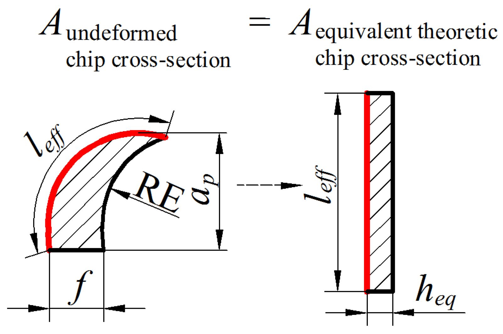
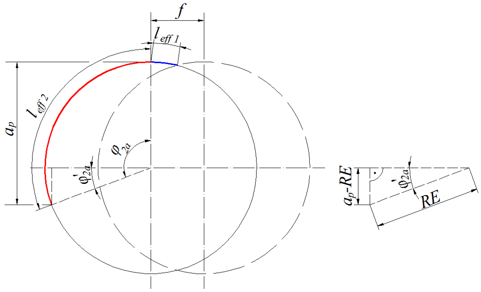
2.3. Adaptation of the Force Model for Round Insert
3. Measurements
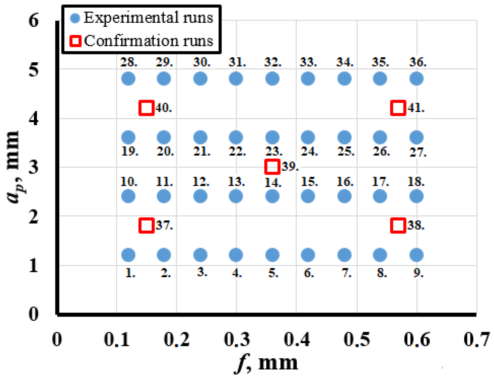
4. Results
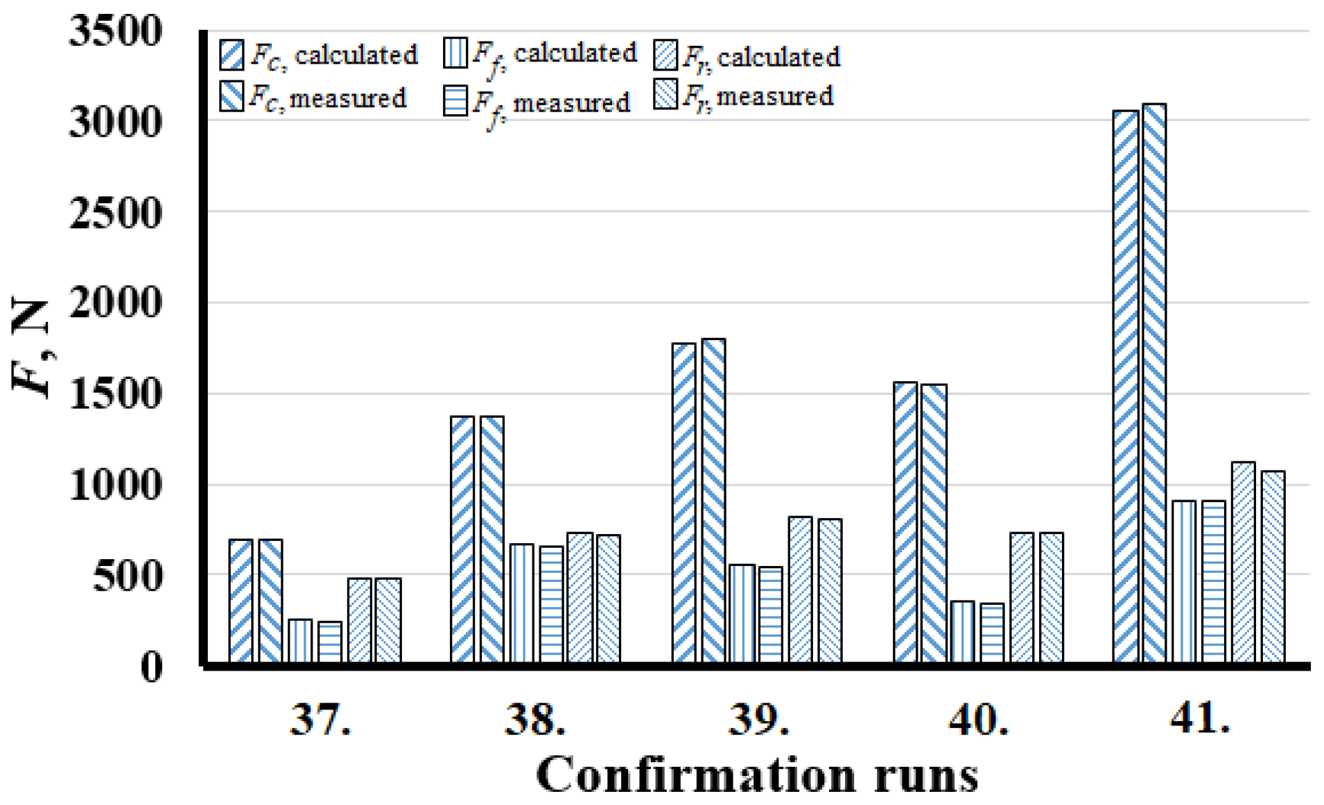
The Model Confirmation
5. Discussion
6. Conclusions
- It was demonstrated that the specific cutting force components (, , ) could be determined in the form of Equation (23) in a wide range of technological parameters with adequate accuracy;
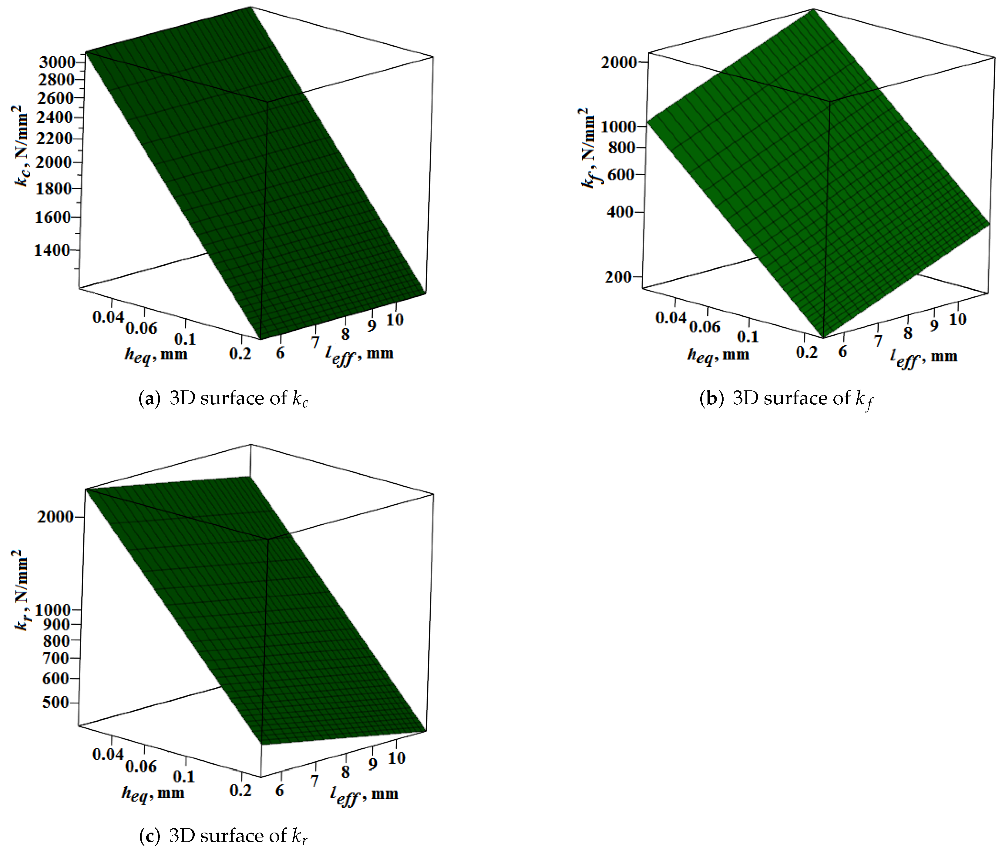
- It was stated that increasing results in higher values of specific cutting forces for each direction;
- The changes of values have a non-significant effect on , but for and have. The increased level of gives a higher value for but a lower one for ;
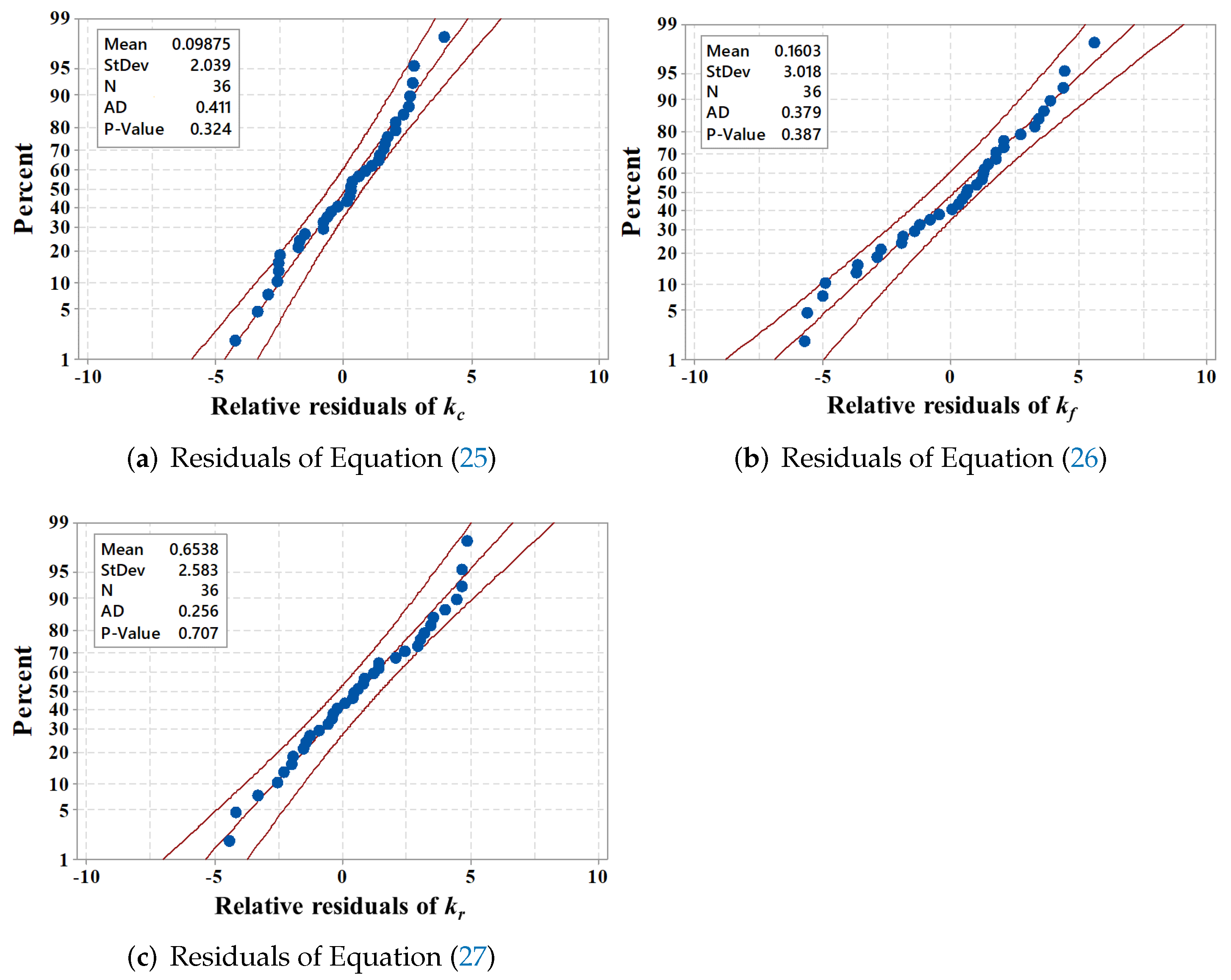
- The residuals of the generated specific force models were examined on normality plots. It was concluded that the residuals follow a normal distribution with a mean of approximately zero. In addition, the standard deviation of the relative deviations is a low value. As a result, the accuracy of the models is proper for technological process planning;
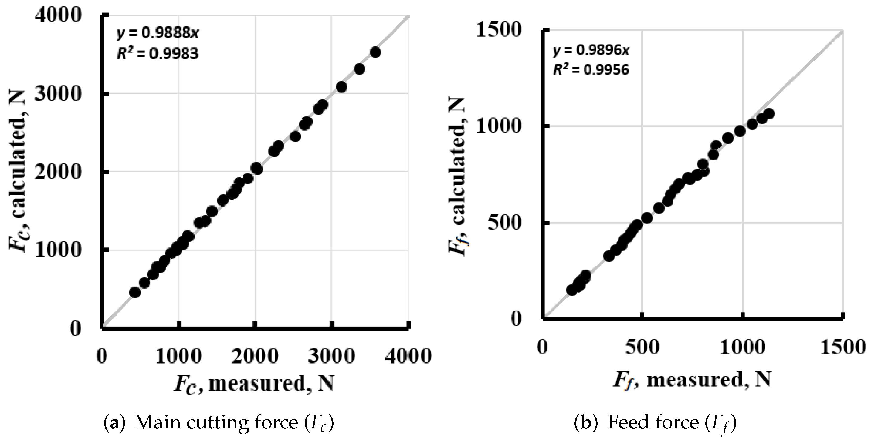
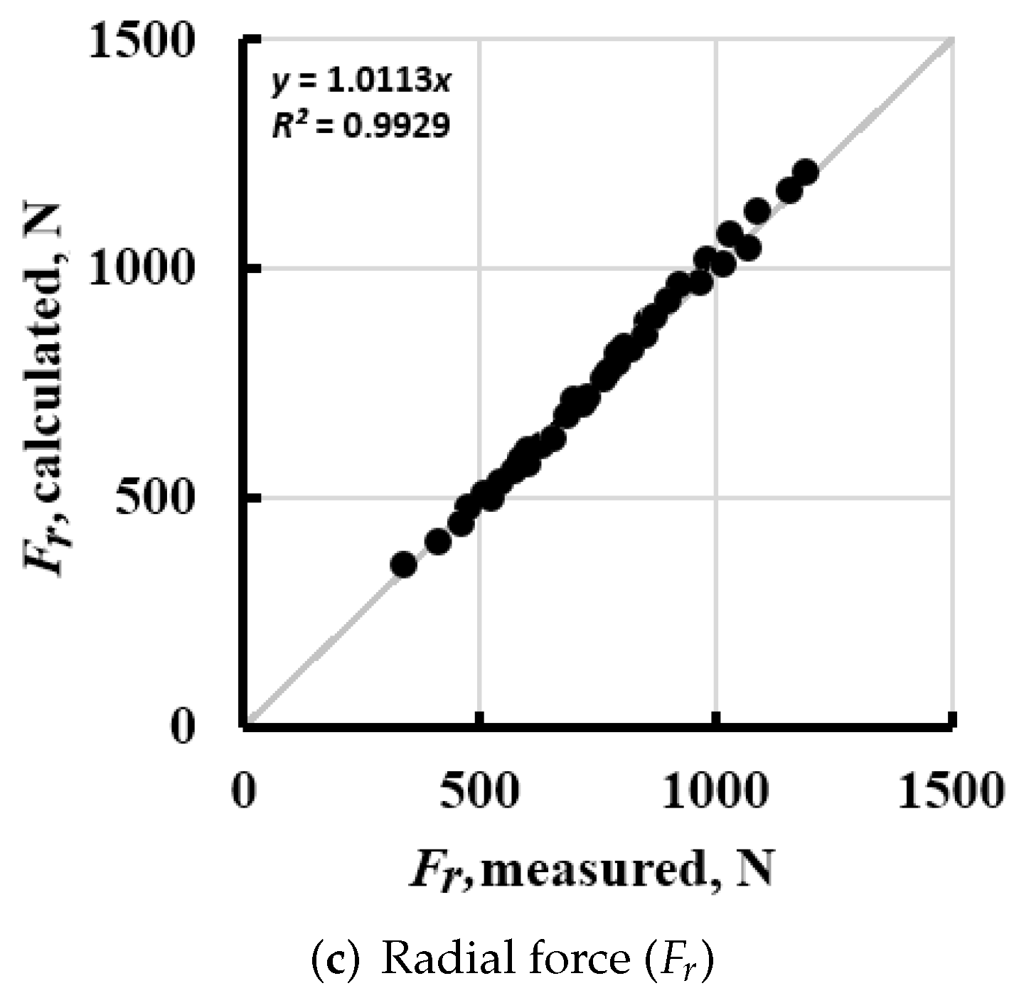
- The accuracy of the created force models handling the special geometric features of the undeformed chip cross-section of round insert is high enough for each component (, , ) in a wide range of technological parameters from roughing to fine technologies. The deviations in the directions are: for main cutting force () −3.79%… +4.43%, for feed force component () −5.4%… +5.99%, and for radial force component () −4.49%… +4.77%;
- The introduced force model can be easily applied for further material types after preliminarily determining the empirical constant by a few properly selected experimental runs. Thus, the process planning procedure can be improved;
- The strengths of the model include that the introduced model operates with easily calculable parameters. However, it can be said that the empirical constants in the phenomenological models are mostly material dependent (tensile strength-hardness) from the workpiece side; which might prognose further studies.
Author Contributions
Funding
Institutional Review Board Statement
Informed Consent Statement
Data Availability Statement
Conflicts of Interest
Abbreviations
| A | chip cross-section, |
| depth of cut, mm | |
| b | chip width, mm |
| C, m, n | empirical constants of the force model |
| Computer Numerical Control | |
| f | feed, mm |
| main cutting force, N | |
| feed force, N | |
| radial force, N | |
| h | chip thickness, mm |
| equivalent chip thickness, mm | |
| cutting edge angle, | |
| , , | specific forces, |
| total length of the engaged cutting edge, mm | |
| tool radius, mm | |
| cutting speed, m/min |
References
- Polini, W.; Carrino, L.; Giorleo, G.; Prisco, U. Dimensional errors in longitudinal turning based on the unified generalized mechanics of cutting approach. Part II: Mechining process analysis and dimensional error estimate. Int. J. Mach. Tools Manuf. 2002, 42, 1517–1525. [Google Scholar]
- Smith, G.T. Cutting Tool Technology: Industrial Handbook; Springer: Berlin/Heidelberg, Germany, 2008. [Google Scholar]
- Gonzalo, O.; Seara, J.M.; Guruceta, E.; Izpizua, A.; Esparta, M.; Zamakona, I.; Uterga, N.; Aranburu, A.; Thoelen, J. A method to minimize the workpiece deformation using a concept of intelligent fixture. Robot. Comput.-Integr. Manuf. 2017, 48, 209–218. [Google Scholar] [CrossRef]
- Outeiro, J.; Dias, A.; Lebrun, J.; Astakhov, V. Machining residual stresses in AISI 316L steel and their correlation with the cutting parameters. Mach. Sci. Technol. 2002, 6, 251–270. [Google Scholar] [CrossRef]
- Germain, D.; Fromentin, G.; Poulachon, G.; Bissey-Breton, S. From large-scale to micromachining: A review of force prediction models. J. Manuf. Process. 2013, 15, 389–401. [Google Scholar] [CrossRef] [Green Version]
- Kienzle, O. Die bestimmung von kräften und Leistungen an spanenden Werkzeugen und Werkzeugmaschinen. VDI-Z 1952, 94, 299–305. [Google Scholar]
- Kienzle, O.; Victor, H. Spezifische schnittkräfte bei der metallbearbeitung. Werkstattstech. Maschinenbau 1957, 47, 224–225. [Google Scholar]
- Bali, J. Forgácsolás (Cutting). In University Textbook (in Hungarian); Tankönyvkiadó: Budapest, Hungary, 1988. [Google Scholar]
- Debongnie, J.F. Cours de Methodes de Fabrication; AEES: Liège, Belgium, 2010. [Google Scholar]
- Illés, D. Gépgyártástechnológia II. (Manufacturing technology II.). In Forgácsoláselmélet, (Cutting Theory) University Textbook (in Hungarian); Miskolci Egyetemi Kiadó: Miskolc, Hungary, 2001. [Google Scholar]
- König, W. Fertigungsverfahren 1: Drehen, Fräsen, Bohren; Springer: Berlin/Heidelberg, Germany, 2008. [Google Scholar]
- Tönshoff, H.K. Spanen: Grundlagen; Springer: Berlin/Heidelberg, Germany, 2013. [Google Scholar]
- Korkut, I.; Boy, M. Experimental examination of main cutting force and surface roughness depending on cutting parameters. Stroj. Vestn. 2008, 54, 531–538. [Google Scholar]
- Günay, M.; Korkut, I.; Aslan, E.; Şeker, U. Experimental investigation of the effect of cutting tool rake angle on main cutting force. J. Mater. Process. Technol. 2005, 166, 44–49. [Google Scholar] [CrossRef]
- Saglam, H.; Yaldiz, S.; Unsacar, F. The effect of tool geometry and cutting speed on main cutting force and tool tip temperature. Mater. Des. 2007, 28, 101–111. [Google Scholar] [CrossRef]
- Velchev, S.; Kolev, I.; Ivanov, K. Research on the influence of the cutting speed on the specific cutting force during turning. Stroj. Vestn. 2009, 55, 400–405. [Google Scholar]
- Fernández-Abia, A.I.; Barreiro, J.; de Lacalle, L.N.L.; Martínez-Pellitero, S. Behavior of austenitic stainless steels at high speed turning using specific force coefficients. Int. J. Adv. Manuf. Technol. 2012, 62, 505–515. [Google Scholar] [CrossRef]
- Aouici, H.; Bouchelaghem, H.; Yallese, M.; Elbah, M.; Fnides, B. Machinability investigation in hard turning of AISI D3 cold work steel with ceramic tool using response surface methodology. Int. J. Adv. Manuf. Technol. 2014, 73, 1775–1788. [Google Scholar] [CrossRef]
- Ahearne, E.; Baron, S. Fundamental mechanisms in orthogonal cutting of medical grade cobalt chromium alloy (ASTM F75). CIRP J. Manuf. Sci. Technol. 2017, 19, 1–6. [Google Scholar] [CrossRef] [Green Version]
- Biró, I.; Szalay, T. Extension of empirical specific cutting force model for the process of fine chip-removing milling. Int. J. Adv. Manuf. Technol. 2017, 88, 2735–2743. [Google Scholar] [CrossRef]
- Guo, Y.; Duflou, J.R.; Qian, J.; Tang, H.; Lauwers, B. An operation-mode based simulation approach to enhance the energy conservation of machine tools. J. Clean. Prod. 2015, 101, 348–359. [Google Scholar] [CrossRef]
- Tapoglou, N.; Mehnen, J.; Butans, J.; Morar, N.I. Online on-board optimization of cutting parameter for energy efficient CNC milling. Procedia CIRP 2016, 40, 384–389. [Google Scholar] [CrossRef] [Green Version]
- Gonçalves, D.A.; Schroeter, R.B. Modeling and simulation of the geometry and forces associated with the helical broaching process. Int. J. Adv. Manuf. Technol. 2016, 83, 205–215. [Google Scholar] [CrossRef]
- Nikolaos, T.; Aristomenis, A. CAD-based calculation of cutting force components in gear hobbing. J. Manuf. Sci. Eng. 2012, 134, 031009. [Google Scholar] [CrossRef]
- Tapoglou, N.; Mammas, A.; Antoniadis, A. Influence of machining data on developed cutting forces in gear hobbing. Int. J. Mach. Mach. Mater. 2013, 14, 66–76. [Google Scholar] [CrossRef]
- Antoniadis, A.; Vidakis, N.; Bilalis, N. A simulation model of gear skiving. J. Mater. Process. Technol. 2004, 146, 213–220. [Google Scholar] [CrossRef]
- Antoniadis, A. Gear skiving–CAD simulation approach. Comput.-Aided Des. 2012, 44, 611–616. [Google Scholar] [CrossRef]
- Kyratsis, P.; Bilalis, N.; Antoniadis, A. CAD-based simulations and design of experiments for determining thrust force in drilling operations. Comput.-Aided Des. 2011, 43, 1879–1890. [Google Scholar] [CrossRef]
- Kyratsis, P.; Tapoglou, N.; Bilalis, N.; Antoniadis, A. Thrust force prediction of twist drill tools using a 3D CAD system application programming interface. Int. J. Mach. Mach. Mater. 2011, 10, 18–33. [Google Scholar] [CrossRef] [Green Version]
- Tapoglou, N.; Antoniadis, A. 3-Dimensional kinematics simulation of face milling. Measurement 2012, 45, 1396–1405. [Google Scholar] [CrossRef]
- De Oliveira, F.B.; Rodrigues, A.R.; Coelho, R.T.; De Souza, A.F. Size effect and minimum chip thickness in micromilling. Int. J. Mach. Tools Manuf. 2015, 89, 39–54. [Google Scholar] [CrossRef]
- Zhang, T.; Liu, Z.; Xu, C. Theoretical modeling and experimental validation of specific cutting force for micro end milling. Int. J. Adv. Manuf. Technol. 2015, 77, 1433–1441. [Google Scholar] [CrossRef]
- Anand, R.S.; Patra, K.; Steiner, M. Size effects in micro drilling of carbon fiber reinforced plastic composite. Prod. Eng. 2014, 8, 301–307. [Google Scholar] [CrossRef]
- Maier, T.; Zaeh, M.F. Modeling of the thermomechanical process effects on machine tool structures. Procedia CIRP 2012, 4, 73–78. [Google Scholar] [CrossRef] [Green Version]
- Ntziantzias, I.; Kechaglas, J.; Fountas, N.; Maropoulos, S.; Vaxevanidis, N.M. A cutting force model in turning of glass fiber reinforced polymer composite. In Proceedings of the International Conference on Economic Engineering and Manufacturing Systems, Brasov, Romania, 24–25 November 2011; pp. 348–351. [Google Scholar]
- Hertel, M.; Dix, M.; Putz, M. Analytic model of process forces for orthogonal turn-milling. Prod. Eng. 2018, 12, 491–500. [Google Scholar] [CrossRef]
- Weng, J.; Zhuang, K.; Zhu, D.; Guo, S.; Ding, H. An analytical model for the prediction of force distribution of round insert considering edge effect and size effect. Int. J. Mech. Sci. 2018, 138, 86–98. [Google Scholar] [CrossRef]
- Zhuang, K.; Weng, J.; Zhu, D.; Ding, H. Analytical modeling and experimental validation of cutting forces considering edge effects and size effects with round chamfered ceramic tools. J. Manuf. Sci. Eng. 2018, 140, 081012. [Google Scholar] [CrossRef]
- Horváth, R. A New Model for Fine Turning Forces. Acta Polytech. Hung. 2015, 12, 109–128. [Google Scholar]
- Horváth, R.; Pálinkás, T.; Mátyási, G.; Drégelyi-Kiss, Á.G. The design, calibration and adaption of a dynamometer for fine turning. Int. J. Mach. Mach. Mater. 2017, 19, 1–16. [Google Scholar] [CrossRef]
- Horváth, R.; Lukács, J. Application of a Force Model Adapted for the Precise Turning of Various Metallic Materials. Stroj. Vestn./J. Mech. Eng. 2017, 63, 489–500. [Google Scholar] [CrossRef] [Green Version]
- Ribeiro Filho, S.L.M.; Pereira, R.B.D.; Lauro, C.H.; Brandão, L.C. Investigation and modelling of the cutting forces in turning process of the Ti-6Al-4V and Ti-6Al-7Nb titanium alloys. Int. J. Adv. Manuf. Technol. 2019, 101, 2191–2203. [Google Scholar] [CrossRef]
- Baro, P.K.; Joshi, S.S.; Kapoor, S. Modeling of cutting forces in a face-milling operation with self-propelled round insert milling cutter. Int. J. Mach. Tools Manuf. 2005, 45, 831–839. [Google Scholar] [CrossRef]
- Ghorbani, H.; Moetakef-Imani, B. Specific cutting force and cutting condition interaction modeling for round insert face milling operation. Int. J. Adv. Manuf. Technol. 2016, 84, 1705–1715. [Google Scholar] [CrossRef]
- Weng, J.; Zhuang, K.; Chen, D.; Guo, S.; Ding, H. An analytical force prediction model for turning operation by round insert considering edge effect. Int. J. Mech. Sci. 2017, 128, 168–180. [Google Scholar] [CrossRef]
- Nieslony, P.; Krolczyk, G.; Chudy, R.; Wojciechowski, S.; Maruda, R.; Biłous, P.; Lipowczyk, M.; Stachowiak, L. Study on physical and technological effects of precise turning with self-propelled rotary tool. Precis. Eng. 2020, 66, 62–75. [Google Scholar] [CrossRef]
- Smith, G.T. Application Guide: Railway Turning, (Re-Turning and New Wheel Turning); Sandvik Coromant: Sandviken, Sweden, 2018. [Google Scholar]
- Bus, C.; Touwen, N.; Veenstra, P.; Van Der Wolf, A. On the significance of equivalent chip thickness. Ann. CIRP 1971, 19, 121–124. [Google Scholar]
- Aouici, H.; Yallese, M.A.; Chaoui, K.; Mabrouki, T.; Rigal, J.F. Analysis of surface roughness and cutting force components in hard turning with CBN tool: Prediction model and cutting conditions optimization. Measurement 2012, 45, 344–353. [Google Scholar] [CrossRef]
- El Hakim, M.; Shalaby, M.; Veldhuis, S.; Dosbaeva, G. Effect of secondary hardening on cutting forces, cutting temperature, and tool wear in hard turning of high alloy tool steels. Measurement 2015, 65, 233–238. [Google Scholar]
- Fetecau, C.; Stan, F. Study of cutting force and surface roughness in the turning of polytetrafluoroethylene composites with a polycrystalline diamond tool. Measurement 2012, 45, 1367–1379. [Google Scholar] [CrossRef]
- Gokkaya, H.; Taskesen, A. The effects of cutting speed and feed rate on BUE-BUL formation, cutting forces and surface roughness when machining Aa6351 (T6) alloy. Stroj. Vestn. 2008, 7, 521–530. [Google Scholar]
- Meddour, I.; Yallese, M.; Khattabi, R.; Elbah, M.; Boulanouar, L. Investigation and modeling of cutting forces and surface roughness when hard turning of AISI 52100 steel with mixed ceramic tool: Cutting conditions optimization. Int. J. Adv. Manuf. Technol. 2015, 77, 1387–1399. [Google Scholar] [CrossRef]
- Nayak, M.; Sehgal, R. Effect of tool material properties and cutting conditions on machinability of AISI D6 steel during hard turning. Arab. J. Sci. Eng. 2015, 40, 1151–1164. [Google Scholar] [CrossRef]
- Wojciechowski, S. The estimation of cutting forces and specific force coefficients during finishing ball end milling of inclined surfaces. Int. J. Mach. Tools Manuf. 2015, 89, 110–123. [Google Scholar] [CrossRef]
- Qiu, W.; Liu, Q.; Yuan, S. Modeling of cutting forces in orthogonal turn-milling with round insert cutters. Int. J. Adv. Manuf. Technol. 2015, 78, 1211–1222. [Google Scholar] [CrossRef]
- Davim, J.P. Mechanical and Industrial Engineering: Historical Aspects and Future Directions; Springer: Berlin/Heidelberg, Germany, 2021. [Google Scholar]


| Exp. Runs | , mm | f, mm | , mm | , mm | A, | , N | , N | , % | , N | , N | , % | , N | , N | , % |
|---|---|---|---|---|---|---|---|---|---|---|---|---|---|---|
| 1 | 1.2 | 0.12 | 5.4723 | 0.0263 | 0.144 | 444 | 443 | −0.13 | 150 | 152 | 1.33 | 340 | 355 | 4.41 |
| 2 | 1.2 | 0.18 | 5.5023 | 0.0393 | 0.216 | 571 | 565 | −1.13 | 173 | 167 | −3.47 | 414 | 405 | −2.17 |
| 3 | 1.2 | 0.24 | 5.5323 | 0.0521 | 0.288 | 675 | 670 | −0.67 | 188 | 179 | −4.79 | 458 | 446 | −2.62 |
| 4 | 1.2 | 0.3 | 5.5623 | 0.0647 | 0.360 | 734 | 766 | 4.43 | 181 | 189 | 4.42 | 474 | 480 | 1.27 |
| 5 | 1.2 | 0.36 | 5.5923 | 0.0772 | 0.432 | 826 | 855 | 3.56 | 190 | 199 | 4.74 | 509 | 510 | 0.20 |
| 6 | 1.2 | 0.42 | 5.6223 | 0.0896 | 0.504 | 914 | 939 | 2.73 | 203 | 207 | 1.97 | 545 | 538 | −1.28 |
| 7 | 1.2 | 0.48 | 5.6523 | 0.1019 | 0.576 | 999 | 1018 | 1.91 | 212 | 215 | 1.42 | 571 | 562 | −1.58 |
| 8 | 1.2 | 0.54 | 5.6823 | 0.1140 | 0.648 | 1065 | 1094 | 2.70 | 214 | 223 | 4.21 | 588 | 585 | −0.51 |
| 9 | 1.2 | 0.6 | 5.7124 | 0.1260 | 0.720 | 1135 | 1166 | 2.77 | 217 | 230 | 5.99 | 600 | 607 | 1.17 |
| 10 | 2.4 | 0.12 | 7.7820 | 0.0370 | 0.288 | 782 | 771 | −1.39 | 332 | 330 | −0.60 | 525 | 502 | −4.38 |
| 11 | 2.4 | 0.18 | 7.8120 | 0.0553 | 0.432 | 977 | 981 | 0.42 | 369 | 362 | −1.90 | 601 | 574 | −4.49 |
| 12 | 2.4 | 0.24 | 7.8420 | 0.0735 | 0.576 | 1153 | 1164 | 0.99 | 398 | 387 | −2.76 | 653 | 631 | −3.37 |
| 13 | 2.4 | 0.3 | 7.8720 | 0.0915 | 0.720 | 1290 | 1330 | 3.13 | 407 | 409 | 0.49 | 686 | 679 | −1.02 |
| 14 | 2.4 | 0.36 | 7.9020 | 0.1093 | 0.864 | 1445 | 1484 | 2.68 | 425 | 428 | 0.71 | 726 | 721 | −0.69 |
| 15 | 2.4 | 0.42 | 7.9320 | 0.1271 | 1.008 | 1597 | 1628 | 1.91 | 439 | 445 | 1.37 | 763 | 759 | −0.52 |
| 16 | 2.4 | 0.48 | 7.9620 | 0.1447 | 1.152 | 1765 | 1764 | −0.08 | 451 | 460 | 2.00 | 791 | 794 | 0.38 |
| 17 | 2.4 | 0.54 | 7.9920 | 0.1622 | 1.296 | 1912 | 1893 | −0.97 | 459 | 475 | 3.49 | 820 | 826 | 0.73 |
| 18 | 2.4 | 0.6 | 8.0220 | 0.1795 | 1.440 | 2050 | 2018 | −1.56 | 473 | 489 | 3.38 | 849 | 855 | 0.71 |
| 19 | 3.6 | 0.12 | 9.6048 | 0.0450 | 0.432 | 1081 | 1068 | −1.22 | 522 | 525 | 0.57 | 632 | 617 | −2.37 |
| 20 | 3.6 | 0.18 | 9.6348 | 0.0673 | 0.648 | 1349 | 1358 | 0.68 | 583 | 575 | −1.37 | 716 | 704 | −1.68 |
| 21 | 3.6 | 0.24 | 9.6648 | 0.0894 | 0.864 | 1596 | 1611 | 0.97 | 626 | 614 | −1.92 | 774 | 774 | 0.00 |
| 22 | 3.6 | 0.3 | 9.6948 | 0.1114 | 1.080 | 1810 | 1840 | 1.68 | 639 | 647 | 1.25 | 808 | 833 | 3.09 |
| 23 | 3.6 | 0.36 | 9.7248 | 0.1333 | 1.296 | 2036 | 2052 | 0.79 | 664 | 676 | 1.81 | 855 | 884 | 3.39 |
| 24 | 3.6 | 0.42 | 9.7548 | 0.1550 | 1.512 | 2260 | 2250 | −0.43 | 683 | 702 | 2.78 | 896 | 931 | 3.91 |
| 25 | 3.6 | 0.48 | 9.7848 | 0.1766 | 1.728 | 2534 | 2438 | −3.79 | 735 | 726 | −1.22 | 968 | 973 | 0.52 |
| 26 | 3.6 | 0.54 | 9.8148 | 0.1981 | 1.944 | 2685 | 2617 | −2.55 | 770 | 748 | −2.86 | 1015 | 1012 | −0.30 |
| 27 | 3.6 | 0.6 | 9.8448 | 0.2194 | 2.160 | 2842 | 2788 | −1.90 | 807 | 769 | −4.71 | 1070 | 1048 | −2.06 |
| 28 | 4.8 | 0.12 | 11.1875 | 0.0515 | 0.576 | 1366 | 1347 | −1.39 | 726 | 733 | 0.96 | 698 | 714 | 2.29 |
| 29 | 4.8 | 0.18 | 11.2175 | 0.0770 | 0.864 | 1712 | 1713 | 0.05 | 800 | 802 | 0.25 | 792 | 815 | 2.90 |
| 30 | 4.8 | 0.24 | 11.2475 | 0.1024 | 1.152 | 2034 | 2032 | −0.10 | 856 | 856 | 0.00 | 871 | 896 | 2.87 |
| 31 | 4.8 | 0.3 | 11.2775 | 0.1277 | 1.440 | 2323 | 2320 | −0.11 | 869 | 902 | 3.80 | 922 | 964 | 4.56 |
| 32 | 4.8 | 0.36 | 11.3075 | 0.1528 | 1.728 | 2656 | 2587 | −2.60 | 925 | 941 | 1.73 | 979 | 1023 | 4.49 |
| 33 | 4.8 | 0.42 | 11.3376 | 0.1778 | 2.016 | 2891 | 2836 | −1.90 | 985 | 977 | −0.81 | 1028 | 1077 | 4.77 |
| 34 | 4.8 | 0.48 | 11.3676 | 0.2027 | 2.304 | 3149 | 3072 | −2.45 | 1047 | 1009 | −3.63 | 1089 | 1125 | 3.31 |
| 35 | 4.8 | 0.54 | 11.3976 | 0.2274 | 2.592 | 3378 | 3297 | −2.41 | 1098 | 1040 | −5.28 | 1155 | 1170 | 1.30 |
| 36 | 4.8 | 0.6 | 11.4276 | 0.2520 | 2.880 | 3591 | 3512 | −2.20 | 1129 | 1068 | −5.40 | 1189 | 1212 | 1.93 |
| Conf. Runs | , mm | , mm | , mm | , mm | , | , N | , N | , % | , N | , N | , % | , N | , N | , % |
| 37 | 1.8 | 0.15 | 0.0401 | 6.7327 | 0.270 | 695 | 697 | 0.33 | 243 | 252 | 3.58 | 479 | 474 | −1.03 |
| 38 | 4.2 | 0.15 | 0.0604 | 10.4335 | 0.630 | 1367 | 1376 | 0.67 | 654 | 661 | 1.10 | 718 | 726 | 1.11 |
| 39 | 3 | 0.36 | 0.1220 | 8.8528 | 1.028 | 1795 | 1769 | −1.44 | 547 | 551 | 0.78 | 810 | 814 | 0.49 |
| 40 | 1.8 | 0.57 | 0.1478 | 6.9428 | 1.026 | 1546 | 1554 | 0.53 | 341 | 352 | 3.26 | 736 | 735 | −0.17 |
| 41 | 4.2 | 0.57 | 0.2249 | 10.6436 | 2.394 | 3093 | 3054 | −1.28 | 909 | 907 | −0.20 | 1076 | 1121 | 4.01 |
Publisher’s Note: MDPI stays neutral with regard to jurisdictional claims in published maps and institutional affiliations. |
© 2022 by the authors. Licensee MDPI, Basel, Switzerland. This article is an open access article distributed under the terms and conditions of the Creative Commons Attribution (CC BY) license (https://creativecommons.org/licenses/by/4.0/).
Share and Cite
Lukács, J.; Horváth, R. Comprehensive Investigations of Cutting with Round Insert: Introduction of a Predictive Force Model with Verification. Metals 2022, 12, 257. https://doi.org/10.3390/met12020257
Lukács J, Horváth R. Comprehensive Investigations of Cutting with Round Insert: Introduction of a Predictive Force Model with Verification. Metals. 2022; 12(2):257. https://doi.org/10.3390/met12020257
Chicago/Turabian StyleLukács, Judit, and Richárd Horváth. 2022. "Comprehensive Investigations of Cutting with Round Insert: Introduction of a Predictive Force Model with Verification" Metals 12, no. 2: 257. https://doi.org/10.3390/met12020257