Article

Comparison on Impact Toughness of High-Strength Metastable β Titanium Alloy with Bimodal and Lamellar Microstructures

1
School of Materials Science and Engineering, Northwestern Polytechnical University, Xi’an 710072, China
2
Northwest Institute for Nonferrous Metal Research, Xi’an 710016, China
3
School of Materials Science and Engineering, Chang’an University, Xi’an 710064, China
4
School of Materials Science and Engineering, Xi’an University of Technology, Xi’an 710048, China
*
Author to whom correspondence should be addressed.
Metals 2022, 12(2), 271; https://doi.org/10.3390/met12020271
Submission received: 30 December 2021 / Revised: 26 January 2022 / Accepted: 31 January 2022 / Published: 1 February 2022
(This article belongs to the Special Issue Lightweight Metals: Process, Microstructure, and Properties)

Abstract

:
The impact toughness of a high-strength metastable β titanium alloy (Ti-5Cr-4Al-4Zr-3Mo-2W-0.8Fe) with two typical microstructures is studied by Charpy impact tests. The bimodal microstructure (BM) and the lamellar microstructure (LM) are obtained by the solution and aging treatments and the β annealing, slow cooling and aging treatments, respectively. In the impact crack initiation process, the deformation capacities of the primary α (αp) phase, secondary α (αs) phase and transformed β (βt) matrix in the BM are very different, and the stress gradient at the interface of the three causes the crack initiation. The lamellar α (αl) phase and βt in the LM satisfy the BOR relationship, and the effective slip transfer between α and β phases slows down the crack initiation. Meanwhile, the appearance of deformation twins in the LM improves the crack initiation energy. In the crack propagation process, the lack of coordinated deformation between the α and β phases in the BM leads to rapid crack propagation. In the LM, the deformation of αl and βt is relatively more coordinated, so the severe plastic deformation is only concentrated near the crack and at the interface. The secondary crack initiation and the crack propagation along the twin boundary reduce the stress concentration at the crack tip. The deformation twins and zigzag propagation path can improve the crack propagation energy. To summarize, the alloy with LM exhibits better impact toughness than the alloy with BM.

1. Introduction

Titanium alloys have been widely developed in the aerospace field due to the advantages of high-specific strength, low density, excellent corrosion resistance and satisfactory crack resistance [1,2,3]. In particular, metastable β titanium alloys have achieved many successful applications in the manufacturing of aircraft structural parts due to their quality hardenability, strong cold working ability, optimum matching of high strength and strong plasticity. With proper heat treatment, metastable β titanium alloys can be applied in a wide range of strengths. Therefore, the microstructure tailoring has great influence on the mechanical properties of alloy; the coordinated deformation between the α and β phases strongly depends on the morphology and quantity of equiaxed and lamellar α phases and the distribution and size of primary and secondary α phases [4,5,6,7].
In the past, material scientists have focused on increasing the strength of titanium alloys to meet the more demanding application requirements on structural materials for the long term [8,9]. However, through the analysis of many engineering failure cases, it has been discovered that the ability of materials to resist crack propagation after damage is also worthy of attention. The impact toughness is used to characterize the crack propagation resistance of materials under dynamic loads, and the energy absorbed per unit area of the surface during a fracture can be obtained by the Charpy impact test as an index to measure the toughness of the material [10,11]. Huang et al. [12] studied the effect of oxygen content on the impact toughness of α titanium alloy and found that the reduction of oxygen content increases the dislocation activity and the number of deformation twins and improves the resistances of crack initiation and propagation. Buirette et al. [13] investigated the impact toughness of the Ti-6Al-4V alloy with bimodal microstructure (BM) and lamellar microstructure (LM) and pointed out that the prismatic slip in the shear band near the crack tip is conducive to the improvement of toughness; the coarse LM can effectively extend the crack propagation path, thus improving the impact toughness. Chi et al. [14] studied the effect of heat treatment on the impact toughness of an extruded tube of Ti-6Al-4V-Mo-Zr alloy and suggested that solution and aging treatments reduce the impact toughness of the alloy with LM. Lei et al. [15] analyzed the impact toughness of the two-phase alloy TC21 with different microstructures and found that the crack initiation energy accounts for most of the total impact energy, and the high-angle interface of the LM leads to the zigzag propagation of crack and increases the crack propagation energy. Xu et al. [16] observed the microstructure evolution of a Ti-17 alloy with LM under impact load after pre-deformation and heat treatment and found that the increase of the spheroidization rate reduces the impact toughness. Yang et al. [17] further studied the effect of aging treatment on the impact toughness of hot-rolled Ti-17 alloy and found that the α phase coarsening after aging changes the crack propagation path and improves the impact toughness. Yao et al. [18] investigated the effect of deformation twins on the impact toughness of the Ti-15Mo alloy and believed that the appearance of deformation twins increases the energy dissipation, and the dynamic grain refinement and twins’ plane promote the deflection of crack propagation path. The titanium alloys involved in the above studies have relatively lower strength than some new metastable β titanium alloys. Therefore, the impact toughness of high-strength metastable β titanium alloys with different microstructures and the corresponding deformation and fracture behaviors under impact load need to be further studied.
In this work, a new high-strength metastable β titanium alloy, Ti-5Cr-4Al-4Zr-3Mo-2W-0.8Fe (Ti-54432), was selected to study the relationship between typical microstructures and impact toughness. The BM and LM were obtained by the solution and aging treatments and the β annealing, slow cooling and aging treatments, respectively. Through uniaxial tensile and Charpy impact tests, the strength and toughness of the alloy with BM and LM were compared. The microstructure, fracture morphology and crack propagation path were observed, and the deformation coordination mechanism between α and β phases under impact load and the crack initiation and propagation in different microstructures were analyzed.

2. Experimental Procedure

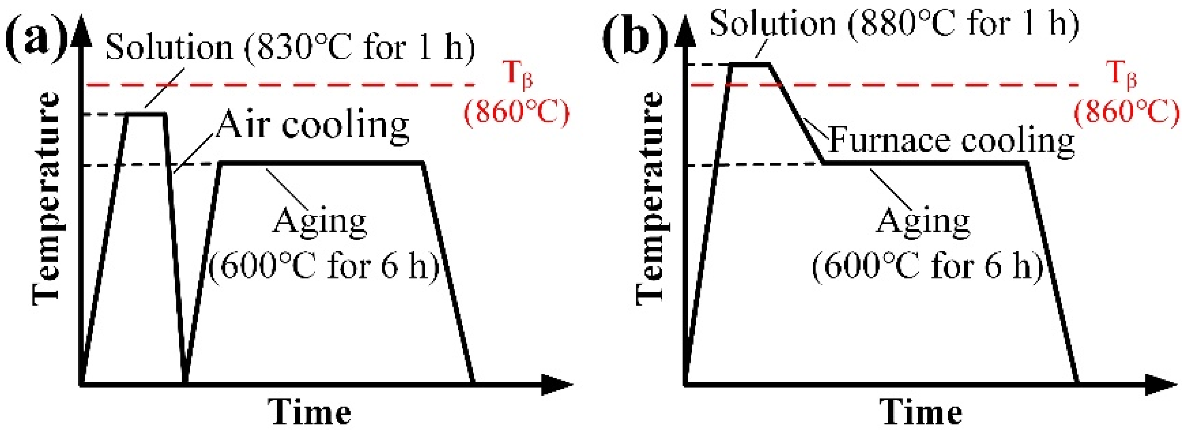
2.1. Material Preparation

The Ti-54432 alloy used in this work is a new high-strength metastable β titanium alloy independently developed by Northwest Institute for Nonferrous Metal Research, China. Table 1 lists the chemical composition of this alloy. To obtain the two target microstructures studied here, the alloy was subjected to a series of thermal-mechanical treatments. The alloy ingot was forged twice above the β transition temperature (Tβ = 860 °C) and then once below Tβ to obtain the forged billet to be heat-treated. The forged billet was cut into two pieces, one of which was solid solution treated at 880 °C (in β phase region) for 1 h and then furnace cooled (FC) to 600 °C for aging of 6 h to obtain the LM; the other piece was solid solution treated at 830 °C (in α + β phase region) for 1 h and air-cooled (AC) to room temperature and then heated to 600 °C for aging of 6 h to obtain the BM. Figure 1 shows the schematic diagram of the two heat treatment processes.

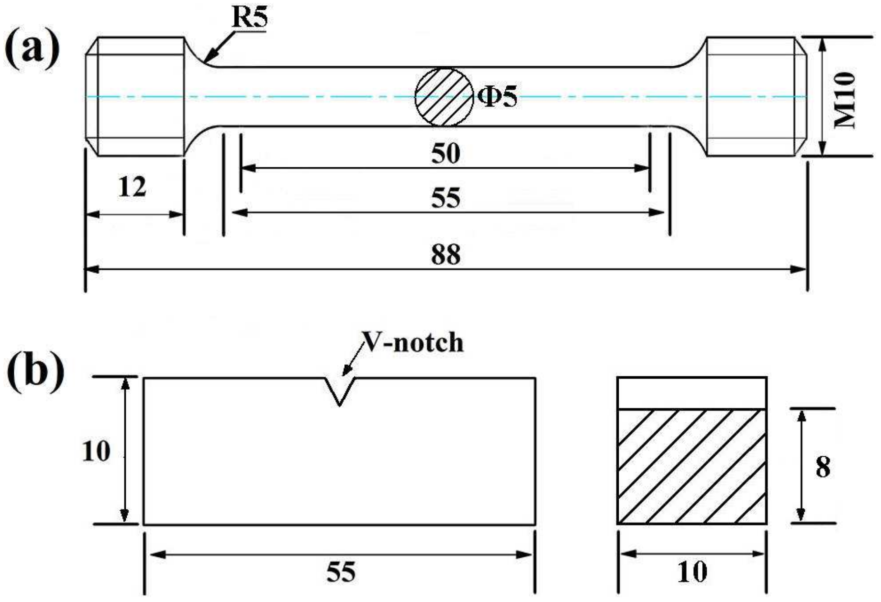
2.2. Uniaxial Tensile and Charpy Impact Tests

Uniaxial tensile tests were conducted by an INSTRON-5975 (INSTRON® Products, Norwood, MA, USA) universal material testing machine with a tensile speed of 2 mm/min at room temperature. The gauge part of the tensile testing specimen is 50 mm in length and 10 mm in diameter. Charpy impact tests were carried out at room temperature by an NI300C 300 J (NCS Ltd., Beijing, China) pendulum impact tester equipped with a data acquisition system. The size of the Charpy impact testing specimen with a V-notch is 10 mm × 10 mm × 55 mm. Figure 2 shows the shape and dimension of the specimens for uniaxial tensile and Charpy impact tests. To ensure the reliability of the data, both the tensile and impact tests were repeated several times to obtain better repeatable testing results.

2.3. Microstructure Characterization

The fracture morphology of the tensile and impact specimens was observed by a JSM-6460 (JEOL Ltd., Showa, Tokyo, Japan) field emission scanning electron microscopy (SEM), and the crystallographic orientation of grains in the area around the crack was analyzed by electron backscatter diffraction (EBSD) combining HKL Channel 5 (Oxford Instruments, Witney, UK) software. The microstructure characterization was performed on a JEM-200 CX (JEOL Ltd., Showa, Tokyo, Japan) transmission electron microscopy (TEM). The TEM thin film specimens were cut from the impact testing specimens parallel to the loading direction; they were sanded down to about 40 μm thickness and blanked into discs with 3 mm diameter, which were, subsequently, twin-jet electropolished at ~58 V for 20 s in the mixed solution of 94 vol% glacial acetic acid and 6 vol% perchloric acid (HClO4).

3. Results

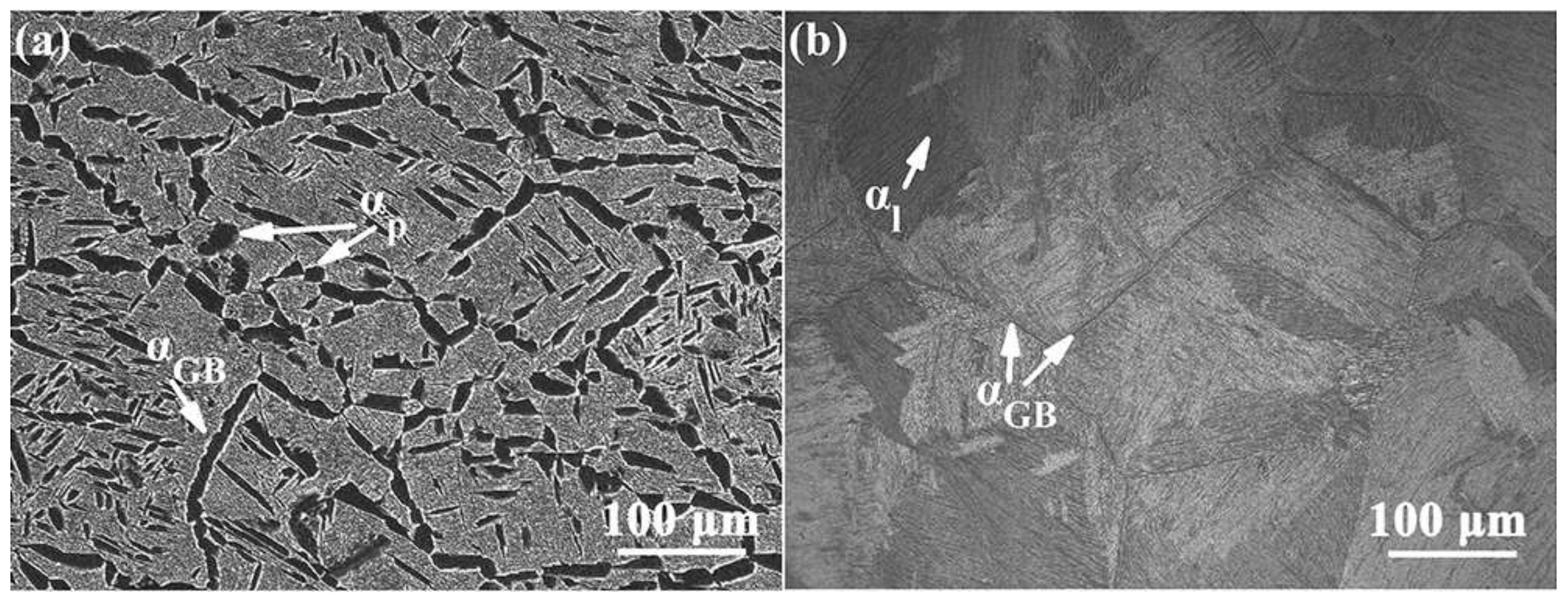
3.1. Initial Microstruture

Figure 3 shows the initial morphology of the BM and LM in the Ti-54432 alloy before deformation and impact. For the alloy with BM, due to the solid solution treatment in the α + β phase region, the equiaxed and rod-like primary α (αp) phases form, while the grain boundary α (αGB) phases precipitate on the original β grain boundary in a discontinuous chain shape. In the subsequent aging process, the fine secondary α (αs) phases uniformly precipitate in the transformed β (βt) matrix [19]. For the alloy with LM, after the solid solution treatment in the β phase region and furnace cooling, the lamellar α (αl) phases generate in the coarse equiaxed β grain, and the αGB is distributed on the β grain boundary. Due to the low rate of furnace cooling, most αl phases nucleate at the β grain boundary and grow inwards to the interior of the grain, forming αl colonies with different orientation and larger thickness. Moreover, the enhanced atomic diffusion results in a more complete β→α transition, and many α stable elements participate in the formation of αl. After aging, only a small amount of short needle-like αs phases precipitate in the βt matrix.

3.2. Uniaxial Tensile Properties

Table 2 lists the tensile properties of the Ti-54432 alloy with different microstructures at room temperature. The alloy with BM has higher strength but lower elongation. This indicates that the equiaxed αp and fine αs are beneficial to the improvement of strength, but their contribution to plasticity is limited. In contrast, the alloy with LM has lower strength and higher elongation. Figure 4 displays the fracture morphology of the Ti-54432 alloy with different microstructures after uniaxial tensile tests. For the alloy with BM, the overall morphology of the fracture shows the characteristics of the ductile fracture, with obvious necking and a relatively flat fracture plane. There is a wide range of shear lip area, consisting of shallow dimples, as shown in the illustration in Figure 4a. At the same time, a large number of fine dimples are densely distributed in the fibrous and radial areas [20]. The microvoids nucleate at the edge and bottom of the dimple, and the microcracks are mainly formed by the coalescence of the grown microvoids [21]. For the alloy with LM, the fracture plane is fluctuant, and the shear lip area is relatively irregular, consisting of larger dimples, as shown in the illustration in Figure 4d. From the magnified view of the fracture, there are characteristics of cleavage fracture [22], which has many cleavage planes.

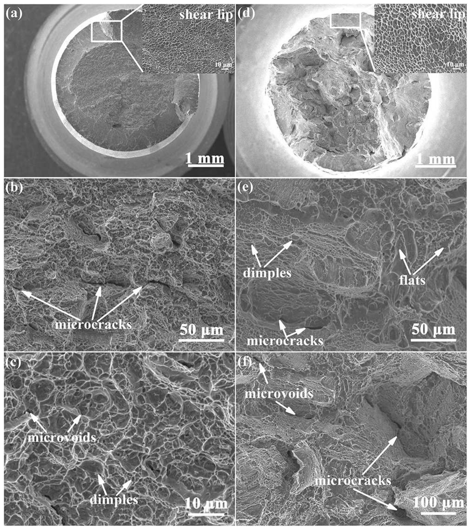
3.3. Charpy Impact Properties

Figure 5 represents the load−displacement curves of the Ti-54432 alloy with different microstructures in the impact tests. The impact energy is generally the sum of the crack initiation energy (WI) and crack propagation energy (WP). In Figure 5a,b, the Fm point can be found, which corresponds the value of the maximum load and divides the whole curve into the crack initiation segment and crack propagation segment. When the load reaches the maximum critical value Fm, the crack propagates rapidly, leading to the specimen fracture. According to the curves, for both the BM and LM, the crack initiation segment is longer than the crack propagation segment. This indicates that it takes a relatively long time for the alloy to go from damage-free to crack initiation; thereinto, the crack initiation displacement of the alloy with LM is about 0.4 mm longer than that of the alloy with BM. Once formed, the crack propagates rapidly in both microstructures. In the BM, the load drops rapidly to 0 after reaching the peak, while in the LM, the deformation can remain for a period after the load reaches the peak, showing that the displacement increases while the load remains unchanged. It is related to the occurrence of stress-induced twins in the LM under impact load, which will be discussed in detail later. The results obtained by integrating the two parts of the load−displacement curves also indicate that the crack initiation energy and crack propagation energy in the LM are higher than those in the BM [23]. In the crack initiation process, the LM absorbs more energy and has stronger crack propagation resistance. Moreover, in the crack propagation process, the small crack propagation energy in the BM indicates that the crack will choose the propagation path with low consumption, and the propagation speed is very fast. Besides the impact energy, the impact toughness (KCV) of the alloy with BM and LM can be respectively determined as 24 J·cm−2 and 36 J·cm−2, which also indicates that the alloy with LM has better crack propagation resistance. It is also worth explaining that the impact toughness of the Ti-54432 alloy is relatively low, whether it has BM or LM, especially compared to some steels with excellent crack propagation resistance [24,25]. The addition of several alloying elements makes the metastable β titanium alloy obtain better solution strengthening, but the plastic deformation ability is relatively poor [10]. Once a crack begins to propagate in high-strength alloys, the low dislocation mobility, limited twins and other deformation modes cannot effectively support the plastic deformation [15]. Especially under dynamic loading, there is no time to activate more movable dislocations. Ti-54432 is such a high-strength alloy, which has poor plasticity compared with other medium-strength titanium alloys, and has few mechanisms conducive to preventing rapid crack propagation. Therefore, it is more meaningful to improve the limited impact toughness by microstructure tailoring.
Figure 6 and Figure 7, respectively, show the fracture surface morphology of the Ti-54432 alloy with BM and LM after impact tests. The impact fracture surface can be divided into three zones [24], namely, the crack initiation zone, containing dimple and cleavage plane; the crack propagation zone, containing dimple, cleavage plane, tearing edge and secondary crack; and the final fracture zone, containing shear lip. For the alloy with BM, the impact fracture is relatively flat, and the shear lip is composed of fine dimples. The narrow crack initiation zone and large number of shallow dimples distributed within are consistent with the characteristics of a ductile fracture [26]. Many microvoids nucleate at the interface between the crack initiation zone and the crack propagation zone, and some transgranular microcracks extend into the propagation zone. For the alloy with LM, the impact fracture is relatively rough and contains many equiaxed β grains. The crack initiation zone is wide, and there are partial cleavage planes. The microvoids at the interface between the crack initiation zone and propagation zone are relatively few. The steps at the grain boundaries and colony interfaces are favorable locations for the microvoid nucleation and microcrack extension, indicating that there is a low energy consumption path for the intergranular propagation. Compared with BM, dimples in the LM are generally larger, showing better toughness of the alloy with LM.
Figure 8 and Figure 9, respectively, display the fracture profile microstructure of the Ti-54432 alloy with BM and LM after impact tests. For the alloy with BM, as the stress concentration caused by dislocation pileup at grain boundary provides a favorable nucleation location for microvoids, the crack initiates at the αp grain boundary with many microvoids and propagates along the grain boundary. Meanwhile, the slip band formed in the αp grain also enables the crack to propagate in the form of transgranular. For the alloy with LM, the crack propagates zigzag in the form of intergranular and transgranular alternation. The αGB is an important crack propagation path with low energy consumption [27]. With the increase of deformation, the increase of microcracks alleviates the local stress concentration, reduces the crack growth rate and consumes more energy. Within a grain, the lamellar colonies with different orientations have different deformation modes due to their various relationship between geometric orientation and stress axis, resulting in the crack propagating along the αl colony boundary or shearing the colony. The junction of different colonies is also the preferred position for microvoid nucleation. The β phase is kinked to coordinate the local stress concentration caused by the surrounding αl and achieve the effect of stress redistribution [28].

4. Discussion

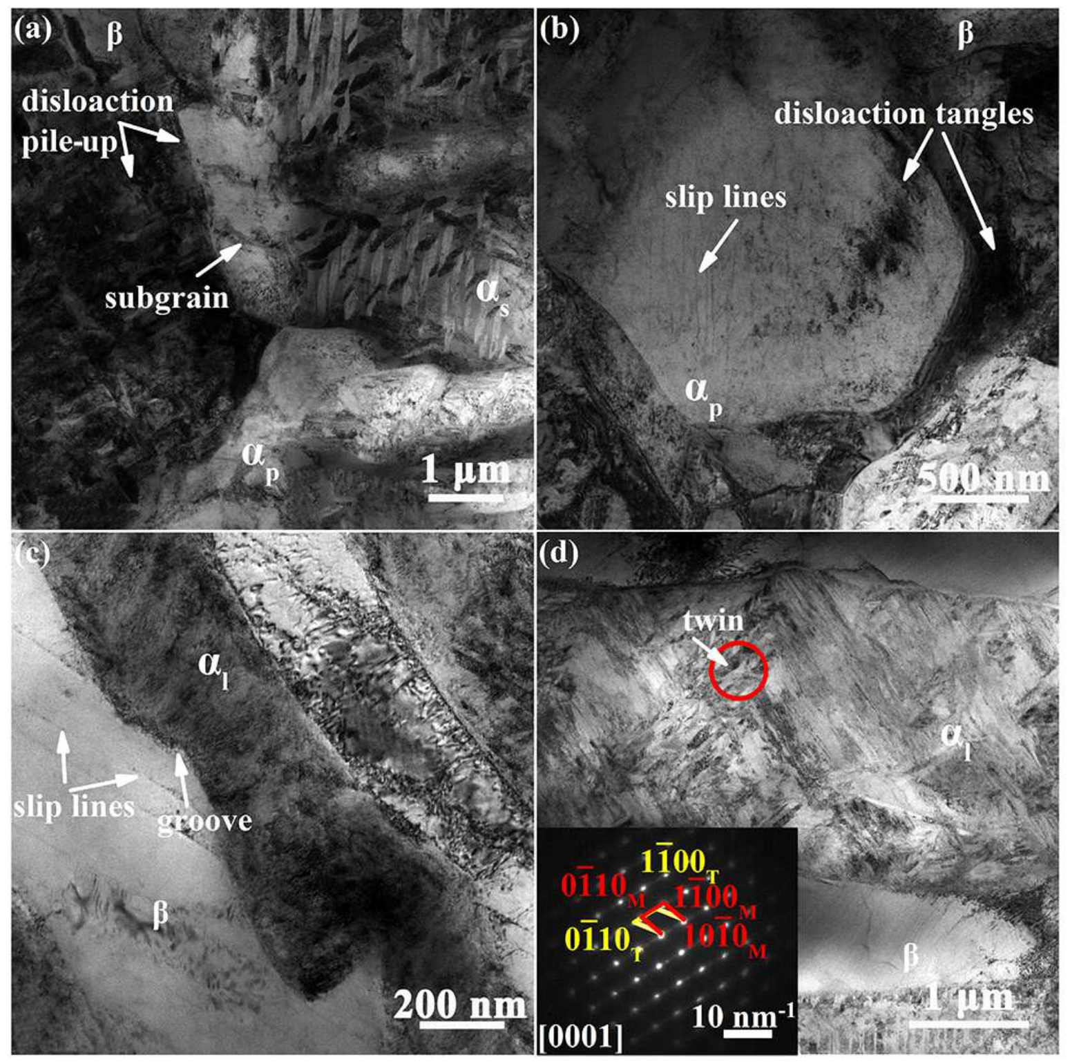
4.1. Deformation Behavior under Impact

Figure 10 represents the TEM images of the Ti-54432 alloy with different microstructures after the impact tests. For the alloy with BM, few slip lines and dislocation tangles appear in αp grains, and dislocation pileup at the αp grain boundaries indicates that the grain boundary as well as phase interface are the preferred locations for microvoid nucleation and crack propagation. The existence of subgrain boundaries in the rod-like αp grains indicates that the cumulative misorientation caused by grain rotation generates in various positions in the interior of grains during deformation. For the alloy with LM, the dislocation pileup at the grain boundary and the uneven stress distribution on the lamellar long edge lead to the inhomogeneous deformation in the αl grain, resulting in the formation of grooves and a shear band on the lamellar boundary. Finally, the αl grain is broken into several small grains. The formation and growth of grooves are affected by the cumulative density of interfacial dislocations [29]. The reason for the above dislocation pileup is that part of the transgranular slip transfer is blocked by the grain boundary, either between two adjacent α grains or between α and β grains. In addition, deformation twins appear in the hard-oriented αl grains, which are small and grow from the grain boundary to the grain interior. The appearance of the deformation twins makes up for the lack of strain in the c-axis direction of hard-oriented grains and also plays a role in coordinating deformation and alleviating stress concentration in the αl grains [30]. The nucleation and growth of twins at the crack initiation stage indicate that the alloy undergoes severe plastic deformation and consumes a large amount of energy. The presence of twin boundaries increases the interface area in the microstructure and plays a role in grain refinement. Meanwhile, as a potential crack propagation path, the twin boundary increases the possibility of zigzag crack propagation [18]. The deformation twins in the crack tip plastic zone relieve stress concentration and consume more energy, and the twin boundaries passivate the crack tip and improve the deformation capacity of the crack tip zone [31]. Based on the above analysis, it can be concluded that due to the larger plastic zone at the crack tip in the lamella, the impact toughness of the alloy with LM is better than that of the alloy with BM.

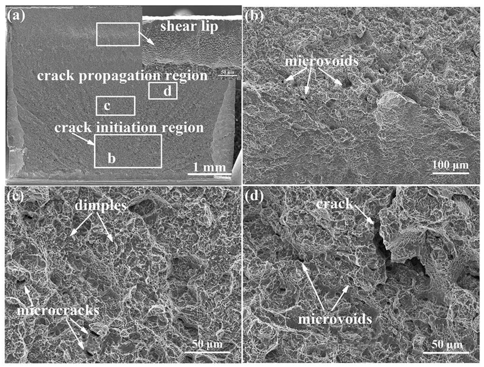
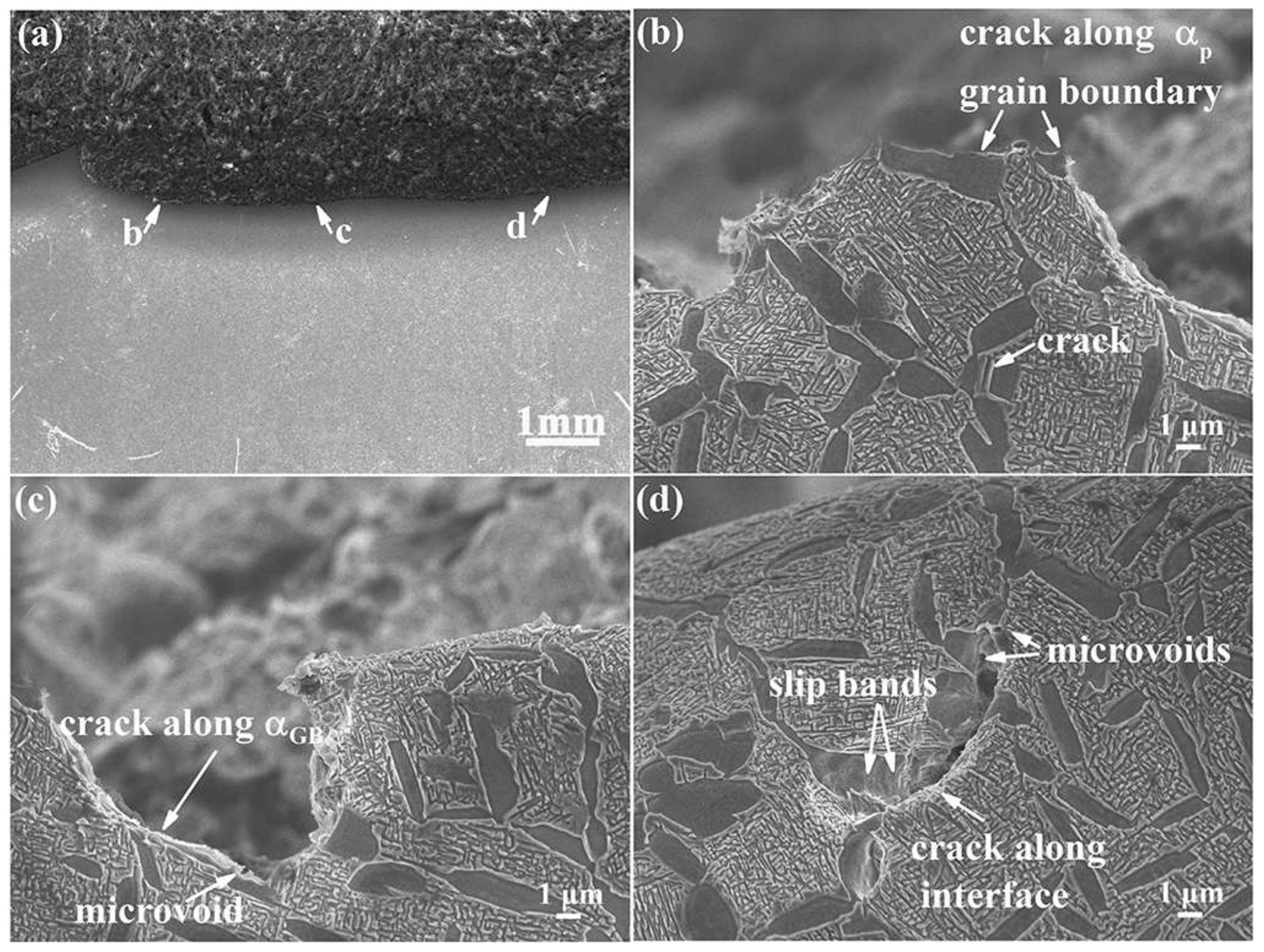
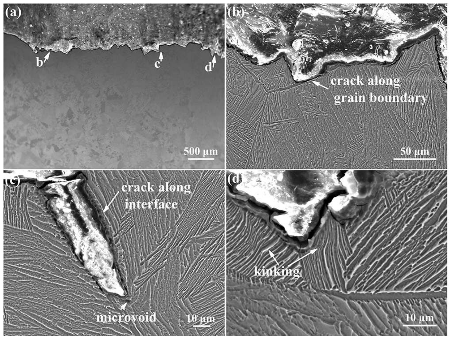
4.2. Crack Propagation under Impact

Figure 11 shows the IPF maps and KAM maps near the fracture profile of the Ti-54432 alloy with different microstructures after impact tests. The grains with similar crystallographic orientation show the same color in the IPF maps, and the KAM value can measure the stress concentration degree inside the material [32]. For the alloy with BM, in the βt matrix, the dislocation density is large and the stress concentration is obvious, which is consistent with the TEM image analysis. The dislocation density in the αp grain is small but at the grain boundary is high, and a certain stress gradient is formed from the grain interior to the grain boundary. For the alloy with LM, the high KAM values are concentrated near the crack, grain boundaries and phase interfaces, indicating these areas have severe inhomogeneous deformation during the deformation process [33].
Figure 12 and Figure 13 exhibit the Schmid factor (SF) maps and distributions of various slip systems in the α and β phases of the Ti-54432 alloy with BM and LM after impact tests, respectively. For the <11 2 ¯ 0> basal slip system and {10 1 ¯ 0 }< 1 ¯ 2 1 ¯ 0> prismatic slip system, their SF value distribution range is from 0 to 0.5, while for the {10 1 ¯ 1 } <1 2 ¯ 10> pyramidal slip system, its SF value distribution range is from 0.3 to 0.5. The peak value of the SF appears in the prismatic and pyramidal slip systems because the c/a ratio of Ti lattice (1.587) is lower than that of ideal hexagonal close-packed lattice (1.633), resulting in the easy activation of the prismatic and pyramidal slip systems [34,35]. The SF value of the oscillation indicates that the misorientation of the grains is accumulated when they rotate about the c-axis during the deformation; thus, the activation of the slip systems in the grains is affected. The activation of the pyramidal slip system and the high SF value prove that the grains near the crack deviate from the uniaxial stress state due to the action of the high-speed impact load. Together, the geometrical orientation and local stress state of the grain affect the deformation mechanism and, thus, affect the SF distribution [36]. Although the calculation accuracy of the SF may be reduced due to large differences in crystallographic orientations and strong anisotropy of alloy mechanical properties, the SF law still applies to most slip analyses [37]. The SF values of the slip systems in the β phase are higher than those in the α phase, indicating that the BCC structure can easily activate the slip systems or even multiple slip systems to coordinate the deformation [38]. It is worth noting that the αl phase and βt phase usually maintain the BOR relationship [39], which favors the slip transfer and the activation of {1 1 ¯ 0}<111> slip system in the LM [5].

5. Conclusions

The tensile properties and impact toughness of the high-strength metastable β titanium alloy Ti-54432 with two typical microstructures were compared with the uniaxial tensile and Charpy impact tests, and the results show that the alloy with LM has the better matching of strength, plasticity and impact toughness than the alloy with BM. The evolution of the two microstructures under impact load and their influences on impact toughness were characterized and analyzed. The main findings can be drawn as follows:
  • In the process of tensile deformation, for the alloy with BM, the inhomogeneous deformation between the αp phases and βt matrix, the uniform precipitation of the αs phases on the βt matrix and the high-density dislocation pileup at the interface all contribute to the improvement of strength, while for the alloy with LM, due to the satisfaction of the BOR relationship between αl phase and βt matrix, the slip transfer promotes the increase of effective slip length, which is not conducive to the improvement of strength.
  • In the process of impact crack initiation, the crack initiation energy of the BM is lower than that of the LM. In the BM, the severe inhomogeneous deformation and the stress gradient among the αp phases, αs phases and βt matrix make the interfaces where a crack easily initiates while in the LM, the coordinated deformation of the αl phases and βt matrix, the rotation and kinking of the αl phases, the occurrence of deformation twinning and the slip transfer at interfaces together reduce the crack initiation tendency and consume more energy.
  • In the process of the impact crack propagation, the crack propagation energy of the BM is lower than that of the LM. In the BM, the crack propagates along the interface of the α and β phases, and the fine αs phase cannot effectively deflect the crack propagation path, so the relatively straight propagation path and low energy consumption are not conducive to the improvement of impact toughness; however, in the LM, the deformation twins, shear band and secondary crack in the lamella effectively deflect and extend the propagation path and increase the energy consumption, resulting in the intergranular and transgranular mixed propagation.
The above findings are helpful to improve the limited crack propagation resistance of high-strength metastable β titanium alloys under impact load and achieve optimum matching of strength, plasticity and impact toughness. Based on these, the influences of temperature, the size and volume fraction of the lamellar phases in the LM and equiaxed phases in the BM on the impact toughness may be of interest for further study.

Author Contributions

Conceptualization, J.W.; methodology, J.W.; software, J.W.; validation, Q.Z. and C.L.; formal analysis, Y.Z. and C.L.; investigation, J.W., W.Z. (Wei Zhou) and W.Z. (Weidong Zeng); resources, Y.Z.; data curation, J.W. and Y.Z.; writing—original draft preparation, J.W. and Y.Z.; writing—review and editing, C.L.; visualization, Q.Z.; supervision, Y.Z. and W.Z. (Wei Zhou); project administration, Y.Z. and W.Z. (Weidong Zeng). All authors have read and agreed to the published version of the manuscript.

Funding

This work was financially supported by the National Natural Science Foundation of China (No. 52101122).

Data Availability Statement

Some or all data and images generated or used during the present work are available from the corresponding authors by reasonable request.

Conflicts of Interest

The authors declare no conflict of interest.

References

  1. Banerjee, D.; Williams, J.C. Perspectives on titanium science and technology. Acta Mater. 2013, 61, 844–879. [Google Scholar] [CrossRef]
  2. Boyer, R.R. An overview on the use of titanium in the aerospace industry. Mater. Sci. Eng. A 1996, 213, 103–114. [Google Scholar] [CrossRef]
  3. Boyer, R.R. Attributes, Characteristics, and applications of titanium and its alloy. JOM 2010, 62, 21–24. [Google Scholar] [CrossRef]
  4. Ahmed, M.; Savvakin, D.G.; Ivasishin, O.M.; Pereloma, E.V. The effect of ageing on microstructure and mechanical properties of powder Ti–5Al–5Mo–5V–1Cr–1Fe alloy. Mater. Sci. Eng. A 2014, 605, 89–97. [Google Scholar] [CrossRef] [Green Version]
  5. Wang, H.; Xin, S.; Zhao, Y.; Zhou, W.; Zeng, W. Plane strain fracture behavior of a new high strength Ti–5Al–3Mo–3V–2Zr–2Cr–1Nb–1Fe alloy during heat treatment. Mater. Sci. Eng. A 2020, 797, 140080. [Google Scholar] [CrossRef]
  6. Sadeghpour, S.; Abbasi, S.M.; Morakabati, M.; Karjalainen, L.P. Effect of dislocation channeling and kink band formation on enhanced tensile properties of a new beta Ti alloy. J. Alloy Compd. 2019, 808, 151741. [Google Scholar] [CrossRef]
  7. Gao, J.; Huang, Y.; Guan, D.; Knowles, A.J.; Ma, L.; Dye, D.; Rainforth, W.M. Deformation mechanisms in a metastable beta titanium twinning induced plasticity alloy with high yield strength and high strain hardening rate. Acta Mater. 2018, 152, 301–314. [Google Scholar] [CrossRef]
  8. Zhu, X.; Fan, Q.; Gong, H.; Ying, J.; Yu, H.; Cheng, X.; Yang, L.; Yang, L.; Li, N.; Li, J. Achieving super-high strength and acceptable plasticity for a near β-type Ti-4.5Mo-5.1Al-1.8Zr-1.1Sn-2.5Cr-2.9Zn alloy through manipulating hierarchical microstructure. Mater. Sci. Eng. A 2021, 825, 141907. [Google Scholar] [CrossRef]
  9. Zhao, G.H.; Ketov, S.V.; Jiang, J.; Mao, H.; Borgenstam, A.; Louzguine-Luzgin, D.V. New beta-type Ti-Fe-Sn-Nb alloys with superior mechanical strength. Mater. Sci. Eng. A 2017, 705, 348–351. [Google Scholar] [CrossRef]
  10. Duan, Q.Q.; Qu, R.T.; Zhang, P.; Zhang, Z.J.; Zhang, Z.F. Intrinsic impact toughness of relatively high strength alloys. Acta Mater. 2018, 142, 226–235. [Google Scholar] [CrossRef]
  11. Keshavarz, M.K.; Sikan, F.; Boutet, C.E.; Milligan, J.; Bois-Brochu, A.; Brochu, M. Impact properties of half stress-relieved and hot isostatic pressed Ti–6Al–4V components fabricated by laser powder bed fusion. Mater. Sci. Eng. A 2019, 760, 481–488. [Google Scholar] [CrossRef]
  12. Huang, S.; Zhao, Q.; Lin, C.; Wu, C.; Zhao, Y.; Jia, W.; Mao, C. Effects of oxygen content on Charpy impact properties and crack resistance of α titanium alloys. Mater. Sci. Eng. A 2021, 818, 141394. [Google Scholar] [CrossRef]
  13. Buirette, C.; Huez, J.; Gey, N.; Vassel, A.; Andrieu, E. Study of crack propagation mechanisms during Charpy impact toughness tests on both equiaxed and lamellar microstructures of Ti–6Al–4V titanium alloy. Mater. Sci. Eng. A 2014, 618, 546–557. [Google Scholar] [CrossRef] [Green Version]
  14. Chi, G.; Yi, D.; Jiang, B.; Yang, L.; Liu, H. Crack propagation during Charpy impact toughness testing of Ti−Al−V−Mo−Zr alloy tubes containing equiaxed and lamellar microstructures. J. Alloy Compd. 2021, 852, 156581. [Google Scholar] [CrossRef]
  15. Lei, L.; Zhao, Q.; Zhao, Y.; Huang, S.; Wu, C.; Jia, W.; Zeng, W. Study on the intrinsic factors determining impact toughness of TC21 alloy. Mater. Charact. 2021, 177, 111164. [Google Scholar] [CrossRef]
  16. Xu, J.; Zeng, W.; Zhao, Y.; Jia, Z. Effect of microstructure evolution of the lamellar alpha on impact toughness in a two-phase titanium alloy. Mater. Sci. Eng. A 2016, 676, 434–440. [Google Scholar] [CrossRef]
  17. Yang, R.; Zhao, F.; Liu, Y.; Shi, K.; Yin, S. Effects of thermomechanical treatment on the evolution pattern of the α phase and mechanical properties of Ti-17 alloy. Mater Today Commun. 2022, 30, 103041. [Google Scholar] [CrossRef]
  18. Yao, K.; Min, X.; Emura, S.; Meng, F.; Ji, X.; Tsuchiya, K. Enhancement of impact toughness of β-type Ti–Mo alloy by {332}<113> twinning. J. Mater Sci. 2019, 54, 11279–11291. [Google Scholar] [CrossRef]
  19. Chen, F.W.; Xu, G.; Zhang, X.Y.; Zhou, K.C.; Cui, Y. Effect of α morphology on the diffusional β ↔ α transformation in Ti–55531 during continuous heating: Dissection by dilatometer test, microstructure observation and calculation. J. Alloy Compd. 2017, 702, 352–365. [Google Scholar] [CrossRef]
  20. Shekhar, S.; Sarkar, R.; Kar, S.K.; Bhattacharjee, A. Effect of solution treatment and aging on microstructure and tensile properties of high strength β titanium alloy, Ti–5Al–5V–5Mo–3Cr. Mater. Des. 2015, 66, 596–610. [Google Scholar] [CrossRef]
  21. Qin, D.; Lu, Y.; Guo, D.; Zheng, L.; Liu, Q.; Zhou, L. Tensile deformation and fracture of Ti–5Al–5V–5Mo–3Cr–1.5Zr–0.5Fe alloy at room temperature. Mater. Sci. Eng. A 2013, 587, 100–109. [Google Scholar] [CrossRef]
  22. Sen, M.; Suman, S.; Banerjee, T.; Bhattacharjee, A.; Kar, S.K. Tensile deformation mechanism and failure mode of different microstructures in Ti 5Al 5Mo 5V 3Cr alloy. Mater. Sci. Eng. A 2019, 753, 156–167. [Google Scholar] [CrossRef]
  23. Wen, X.; Wan, M.; Huang, C.; Tan, Y.; Lei, M.; Liang, Y.; Cai, X. Effect of microstructure on tensile properties, impact toughness and fracture toughness of TC21 alloy. Mater. Des. 2019, 180, 107898. [Google Scholar] [CrossRef]
  24. Panin, S.V.; Maruschak, P.O.; Vlasov, I.V.; Ovechkin, B.B. Impact toughness of 12Cr1MoV steel. Part 1 – Influence of temperature on energy and deformation parameters of fracture. Theor. Appl. Fract. Mec. 2016, 83, 105–113. [Google Scholar] [CrossRef]
  25. Panin, S.V.; Maruschak, P.O.; Vlasov, I.V.; Sergeev, V.P.; Ovechkin, B.B.; Neifeld, V.V. Impact toughness of 12Cr1MoV steel. Part 2 – Influence of high intensity ion beam irradiation on energy and deformation parameters and mechanisms of fracture. Theor. Appl. Fract. Mec. 2016, 83, 82–92. [Google Scholar] [CrossRef]
  26. Dudko, V.; Fedoseeva, A.; Kaibyshev, R. Ductile-brittle transition in a 9% Cr heat-resistant steel. Mater. Sci. Eng. A 2017, 682, 73–84. [Google Scholar] [CrossRef]
  27. Foltz, J.W.; Welk, B.; Collins, P.C.; Fraser, H.L.; Williams, J.C. Formation of Grain Boundary α in β Ti Alloys: Its Role in Deformation and Fracture Behavior of These Alloys. Metall. Mater. Trans A 2010, 42, 645–650. [Google Scholar] [CrossRef]
  28. Tian, X.J.; Zhang, S.Q.; Li, A.; Wang, H.M. Effect of annealing temperature on the notch impact toughness of a laser melting deposited titanium alloy Ti–4Al–1.5Mn. Mater. Sci. Eng. A 2010, 527, 1821–1827. [Google Scholar] [CrossRef]
  29. Zhang, J.; Li, H.; Sun, X.; Zhan, M. A multi-scale MCCPFEM framework: Modeling of thermal interface grooving and deformation anisotropy of titanium alloy with lamellar colony. Int. J. Plast. 2020, 135, 102804. [Google Scholar] [CrossRef]
  30. Qin, H.; Jonas, J.J.; Yu, H.; Brodusch, N.; Gauvin, R.; Zhang, X. Initiation and accommodation of primary twins in high-purity titanium. Acta Mate. 2014, 71, 293–305. [Google Scholar] [CrossRef]
  31. Hrabe, N.; White, R.; Lucon, E. Effects of internal porosity and crystallographic texture on Charpy absorbed energy of electron beam melting titanium alloy (Ti-6Al-4V). Mater. Sci. Eng. A 2019, 742, 269–277. [Google Scholar] [CrossRef]
  32. Zhou, Y.; Wang, K.; Yan, Z.; Xin, R.; Wei, S.; Wang, X.; Liu, Q. Ex-situ study on mechanical properties and deformation mechanism of three typical microstructures in TA19 titanium alloy. Mater. Charact. 2020, 167, 110521. [Google Scholar] [CrossRef]
  33. Birosca, S.; Buffiere, J.Y.; Garcia-Pastor, F.A.; Karadge, M.; Babout, L.; Preuss, M. Three-dimensional characterization of fatigue cracks in Ti-6246 using X-ray tomography and electron backscatter diffraction. Acta Mater. 2009, 57, 5834–5847. [Google Scholar] [CrossRef]
  34. Lei, L.; Zhao, Q.; Wu, C.; Zhao, Y.; Huang, S.; Jia, W.; Zeng, W. Variant selection, coarsening behavior of α phase and associated tensile properties in an α+β titanium alloy. J. Mater. Sci. Technol. 2022, 99, 101–113. [Google Scholar] [CrossRef]
  35. Zhao, Z.; To, S. An investigation of resolved shear stress on activation of slip systems during ultraprecision rotary cutting of local anisotropic Ti-6Al-4V alloy: Models and experiments. Int. J. Mach. Tool. Manu. 2018, 134, 69–78. [Google Scholar] [CrossRef]
  36. Wang, L.; Fan, X.G.; Zhan, M.; Jiang, X.Q.; Zeng, X.; Liang, Y.F.; Zheng, H.J.; Zhao, A.M. The heterogeneous globularization related to crystal and geometrical orientation of two-phase titanium alloys with a colony microstructure. Mater. Des. 2020, 186, 108338. [Google Scholar] [CrossRef]
  37. Briffod, F.; Bleuset, A.; Shiraiwa, T.; Enoki, M. Effect of crystallographic orientation and geometrical compatibility on fatigue crack initiation and propagation in rolled Ti-6Al-4V alloy. Acta Mater. 2019, 177, 56–67. [Google Scholar] [CrossRef]
  38. Wang, J.; Zhao, Y.; Zhou, W.; Zhao, Q.; Huang, S.; Zeng, W. In-situ investigation on tensile deformation and fracture behaviors of a new metastable β titanium alloy. Mater. Sci. Eng. A 2021, 799, 140187. [Google Scholar] [CrossRef]
  39. Wang, J.; Zhao, Y.; Zhou, W.; Zhao, Q.; Lei, C.; Zeng, W. In-situ study on tensile deformation and damage evolution of metastable β titanium alloy with lamellar microstructure. Mater. Sci. Eng. A 2021, 824, 141790. [Google Scholar] [CrossRef]
Figure 1. Schematic diagram of the heat treatment processes to obtain two target microstructures: (a) BM; (b) LM.
Metals 12 00271 g001
Figure 2. Shape and dimension (unit: mm) of specimens for the uniaxial tensile test (a) and the Charpy impact test (b).
Metals 12 00271 g002
Figure 3. SEM images of the Ti-54432 alloy with different microstructures before deformation and impact: (a) BM; (b) LM.
Metals 12 00271 g003
Figure 4. SEM images of the fracture morphology of the Ti-54432 alloy with different microstructures after uniaxial tensile tests: (a) overall appearance of the BM; (b) microcrack of the BM; (c) microvoid of the BM; (d) overall appearance of the LM; (e) cleavage plane of the LM; (f) microcrack of the LM.
Metals 12 00271 g004
Figure 5. Load−displacement curves of the Ti-54432 alloy with BM (a) and LM (b) in impact tests; comparisons of absorbed energy evolution (c) and crack initiation energy and crack propagation energy (d).
Metals 12 00271 g005
Figure 6. SEM images of the fracture surface morphology of the Ti-54432 alloy with BM after impact tests: (a) overall appearance; (b) microvoids; (c) dimples; (d) crack.
Metals 12 00271 g006
Figure 7. SEM images of the fracture surface morphology of the Ti-54432 alloy with LM after impact tests: (a) overall appearance; (b) cleavage plane; (c) crack; (d) dimples.
Metals 12 00271 g007
Figure 8. SEM images of the fracture profile microstructure of the Ti-54432 alloy with BM after impact tests: (a) overall appearance; (b,c) crack initiation zone; (d) crack propagation zone.
Metals 12 00271 g008
Figure 9. SEM images of the fracture profile microstructure of the Ti-54432 alloy with LM after impact tests: (a) overall appearance; (b,c) crack initiation zone; (d) crack propagation zone.
Metals 12 00271 g009
Figure 10. TEM images of the Ti-54432 alloy with different microstructures after impact tests: (a) dislocation pileup in the BM; (b) slip lines in the BM; (c) groove on αl in the LM; (d) deformation twins in the LM.
Metals 12 00271 g010
Figure 11. EBSD images near the fracture profile of the Ti-54432 alloy with different microstructures after impact tests: (a) IPF maps of the BM; (b) KAM maps of the BM; (c) IPF maps of the LM; (d) KAM maps of the LM.
Metals 12 00271 g011
Figure 12. SF maps and distributions of the various slip systems in the α and β phases of the Ti-54432 alloy with BM after impact tests: (ac) <11 2 ¯ 0> direction of the α phase; (df) <111> direction of the β phase.
Metals 12 00271 g012
Figure 13. SF maps and distributions of the various slip systems in the α and β phases of the Ti-54432 alloy with LM after impact tests: (ac) <11 2 ¯ 0> direction of the α phase; (df) <111> direction of the β phase.
Metals 12 00271 g013
Table 1. Chemical composition of the Ti-54432 alloy (wt.%).
AlCrZrMoWFeOTi
4.105.333.992.632.090.830.08Bal.
Table 2. Tensile properties of the Ti-54432 alloy with different microstructures at room temperature.
MicrostructureUTS/MpaYS/MpaElongation/%Area Reduction/%
BM129212621026
LM1125109313.522
Publisher’s Note: MDPI stays neutral with regard to jurisdictional claims in published maps and institutional affiliations.

