Article

Frictional Behavior and Mechanical Performance of Al Reinforced with SiC via Novel Flake Powder Metallurgy

by
Nabeel H. Alharthi
1,
Saud M. Almotairy
2,* and
Abdulrahman M. Almutairi
2
1
Mechanical Engineering Department, King Saud University, P.O. Box 800, Al-Riyadh 11421, Saudi Arabia
2
Center of Excellence for Research in Engineering Materials (CEREM), King Saud University, P.O. Box 800, Riyadh 11421, Saudi Arabia
*
Author to whom correspondence should be addressed.
Metals 2022, 12(2), 323; https://doi.org/10.3390/met12020323
Submission received: 9 January 2022 / Revised: 27 January 2022 / Accepted: 8 February 2022 / Published: 12 February 2022
(This article belongs to the Special Issue Advanced Research of Metal Matrix Composites)

Abstract

:
This paper targets developing new low-cost sustainable materials. To achieve this objective, aluminum was utilized as base material for metal matrix nanocomposites (MMNC). Three routes of advanced manufacturing techniques were designed and implemented. Flake powder metallurgy as a reliable method to synthesis nanocomposites powder was employed. By reinforcing aluminium with SiC and using a similar amount of both constitutes, three metal matrix nanocomposites (MMNCs) with different properties were produced. The ball milled powder were characterized using filed emission scanning electron microscope (FE-SEM) to analyze the morphology of the powder. Different investigations and analysis were conducted on the produced samples. These include X-ray diffraction (XRD) analysis, density and porosity, mechanical properties, and frictional performance. The obtained results include relative density, Young’s modulus, compressive yield strength, elongation, toughness, hardness, coefficient of friction, and specific wear rate. Achieving superior mechanical and tribological performance is evident from these results. This is accredited to the homogeneity of the reinforcement dispersion within the aluminum matrix.

1. Introduction

The curiosity toward developing low-cost sustainable materials is in an ascendant trend in the recent decades. The fundamental objective has been always to meet the tremendous call for advanced materials in various applications including aerospace and military [1,2,3] and many other applications. Utilization of aluminum as one of the most plentiful metals found on the earth is a major path for sustainability [4]. Moreover, its light weight and recyclability [5] lead to energy efficiency and pollution reduction [6]. However, aluminum in its monolithic form have low elastic modulus limiting its usage in different load-bearing applications [7]. In fact, monolithic materials rarely have the ability of combining contradicted mechanical properties [8]. Thus, there is a growing attention toward cutting-edge materials, which owing to their enhanced properties are expected to supplant available materials [9]. Among these cutting-edge materials are aluminum metal matrix composites (AMMCs) [10]. Metal matrix composites (MMCs), in general, have shown promise by combining or further enhancing the properties [11,12,13,14,15]. AMMCs, specifically, have shown unlevered potential as structural materials [16,17] for a broad spectrum of industrial applications [18,19] such as automotive and aerospace [20]. This is attributed to the conceivable alteration of their strength, hardness, and other mechanical properties [21,22,23]. Moreover, downsizing the reinforcements to nano size can lead to better properties [24], even when the fraction incorporated is small [25]. Usually, when the reinforcement is nano-size (i.e., has at least one dimension below 300 nm), then the product is classified as metal matrix nanocomposites (MMNCs) [26]. Additionally, SiC nanoparticles are widely used as a reinforcement of aluminum MMNCs [27], which improve the abrasive wear, strength and toughness [28]. However, the penchant of nanoparticles to agglomerate is high [29], impeding homogenous dispersion and hindering the achievement of the desirable properties [30]. Nonetheless, the homogenous distribution of the reinforcement can be controlled by the selection of the suitable fabrication technique and adjusting its parameters [31]. Nevertheless, properties both tribological and mechanical are considerably affected by the routes of production and their related parameters [32,33]. As has been reported by Liu et al. [34], the excellent mechanical properties are usually associated with eminent wear resistance.
Thus, for the sake of uniform distribution of nanoparticles within aluminum MMNCs [35], and accordingly, boosting mechanical and tribological properties [36], a number of fabrication techniques were developed. Each of these techniques has its own advantages and disadvantages [37]. In general, these techniques are categorized into either solid-state or liquid-state processing techniques [38]. Solid state processing techniques generally involve powder metallurgy (PM). PM is considered one of the most flexible techniques [39] and can be divided into three main stages: mixing the powder of the base matrix and the reinforcement, compacting the mixed powder, and lastly, sintering the composite into bulk form [12,40]. The mixing stage can be utilized in high-energy ball milling (HEBM); however, if, the difference between the particle size of the base matrix and the nano--reinforcement, agglomeration of nanoparticles could take place [41,42], hindering the formability of the composites in the subsequent process [43,44,45]. For this reason, PM is not the ultimate proper technique for uniform distribution of nanoparticles within the matrix. This, therefore, makes it indispensable to develop effective and practical techniques providing uniform dispersion of nanoparticles and hence, boosted mechanical and tribological properties.
The past decade has witnessed the emergence of flake powder metallurgy (FPM) as an entrenched solid state method for MMNCs production. Morsi and Esawi [46] pointed to the flattening that takes place in aluminum particles when they are mechanically milled, which produces flake shape particles. Moreover, Hesabi et al. [47] assured that the spherical particles can become flaky, signifying their high ability in accommodating nanoparticles. Jiang et al. [48] reported for first time about an advanced technique called “flake powder metallurgy”, where the formulation of aluminum flakes is taking place. In [49], they used this technique to fabricate a ductile, yet highly strong Al/CNT nanocomposite, with superior results. Furthermore, Kai et al. [50] employed FPM to produce Al/B4C composite, achieving high strength and good ductility. Many studies [35,38,49,50,51,52,53,54,55,56] were undertaken to implement and further investigate this procedure where some advancement was reached. Among these advancements of FPM, in 2017, there was a projection and application of a highly tuned strategy to attain good ductility with improved strength by Xu et al. [57]. The main characteristic of this route was the utilization of low speed followed by high speed within one process with the intention of employing the advantages of each one. They affirmed that their results were very motivating and endorsed their achievements of attaining good dispersion and interfacial bonding. This route was implemented primarily with CNTs and graphene as the secondary constituents in the composites [58,59,60].
In this research, a novel technique will be used, altered, and manipulated into three different routes to produce different nanocomposites using fixed amounts of SiC as reinforcement and aluminum as base matrix. Mechanical and frictional properties of the produced nanocomposites will be investigated to attribute their enhancements into the parameters of the utilized techniques.

2. Experimental Procedures

2.1. Materials

To compose the new materials, aluminum fine powder of 30 µm average size obtained from Loba Chemie (Mumbai, India) were reinforced by 2 wt.% of SiC nanoparticles with an average size of 60 nm bought from Alfa Aesar (Kandel, Germany).

2.2. Ball Milling Processing Routes

Three different processing routes were designed to produce the targeted nanocomposites. The objective is to investigate the effect of each processing route on the frictional and mechanical performance. The alteration of these routes aims to obtain different materials. S0, S1, and S2 nominate both the processing routes and the obtained materials. The processing phases are illustrated in Table 1. In the first processing route, the ball milling was started at 150 rpm for 8 h of actual milling time, then the speed was shifted up to 300 rpm for another 4 h of actual milling time. In the second processing route, the same processes were utilized with the extension of shifting speed down to 150 rpm for 2 h of actual milling time. This extension was replaced in the third processing route with shifting the speed upward to 450 rpm for 1 h of actual milling time. This design for the processing routes allows for exploring the power of speed shifting in producing flake-like particles. These flaky particles, in turn, are effective in reaching homogenous distribution of nanoparticle in the AMMCs.
In each patch of the ball milling process, 5 g of mixture was used, including 2 wt.% of stearic acid to avoid severe cold welding. A 15:1 ball-to-powder ratio was used in all processes. To allow for cooling, an uninterrupted ball milling process was implemented with 15 min of milling and 15 min of stoppage. The ball milling process was conducted using a planetary ball mill (Pulverisette 7, Fritsch, Idar-Oberstein, Germany) with milling jars of 80 mL in size.

2.3. Consolidation

A high-frequency induction heat sintering furnace (HFIHS) from ELTek Co., (Anyang, South Korea) was used to consolidate the ball milled powder. This furnace allows for the compaction and sintering processes to take place simultaneously in an ultimately short time. To preserve the state of the aluminum elements in their solid state and avoid any partial conversion into liquid state, the temperature of HFIHS was maintained approximately 20% below the solidus temperature of the aluminum.
Graphite dies of 10-mm inner diameter were used to form the bulk specimens. The ball milled powder was loaded into the graphite die in an evacuated chamber at 1 × 10⁻³ Torr, and a uniaxial pressure of 40 MPa was applied throughout the sintering process. The heat for the sintering process was generated at 150 °C/min rate by applying a strong magnetic field in the electrically conducting die and the sample itself. The temperatures were measured using a pyrometer built in HFIHS. The holding time was 5 min. These parameters were kept consistent in all process in this study.

2.4. Characterizations and Testing

Several characterizations and testing were conducted to allow for drawing the conclusion. Firstly, field emission scanning electron microscopy (FE-SEM) (JEOL Ltd., Tokyo, Japan) was used for morphological analysis of the synthesized powder. Thus, insight into the morphological evolution, powder characteristics, and reinforcement homogeneity within the matrix can be gained. Additionally, consolidated bulk nanocomposites were polished, and different readings were recorded. These readings include size using caliper, actual densities using Archimedes ‘method, and hardness using Vickers hardness tester at 5 kN load. Relative densities for all samples were calculated using the theoretical density calculated using the mixture rule and the measured density. The relative density, in turn, was used to calculate the porosity. Additionally, these bulk nanomaterials were inspected for their chemical composition using X-ray Diffraction. Moreover, the 5582 Microtester (Instron, Norwood, MA, USA) was utilized to conduct a compression test at room temperature and strain rate of 10−3/s.
Additionally, frictional behavior was tested using a pin-on-disc test device made in our lab (Riyadh, Saudi Arabia). The test was employed in a dry sliding condition for the samples according to ASTM G99-95. The pin was symbolized by the nanocomposite specimen with 10 mm diameter and 15 mm height, while the contact surface was 78.5 mm2. The disk was a stainless steel with 20 cm diameter and 13 μm roughness. With the aim of avoiding any contamination, a series of samples preparations for wear test were conducted including comprehensive polishing using fine-grade sandpaper, washing using acetone solution, and drying under high-pressure air jet. Furthermore, an electronic balance (Hanchen, Ostfildern, Germany) was used to measure the weight of each sample with accuracy to a part of 10 thousand before and after the wear test. For wear testing, a constant 10 N load was used to perform the wear test. The rotational speed was set to 100 rpm and the track diameter was set to 150 mm. Each test was repeated 5 times to assure the repeatability. Calculation of friction coefficient and specific wear rate considering standard error were conducted.

3. Results and Discussion

3.1. Morphological Analysis

The morphological analysis of the synthesized powder is a key in understanding the ball milling process. It is a convenient method to examine the distribution of the reinforcement into the matrix, and the size of the particles. The morphological evolution explains how the tribological and mechanical performance of the produced nanocomposites were affected by the different routes utilized for the powder synthesizing. Thus, employing FE-SEM resulted in providing images for the synthesized ball milled powder demonstrating the three different fabrication tracks in this study as shown in Figure 1, Figure 2 and Figure 3. These images uncover the powder morphology changes as a consequence of the variation of the parameters of the milling tracks.
Figure 1 presents the morphology of the powder produced by the first route including three different types of magnifications. This route started with low speed and shifted up once into a higher speed. It can be seen that the mainstream of the particles in this powder has uniform size and flake shape. Moreover, it is depicted that a small number of particles are fragmented and a partial amount of these soft fragmented Al particles is laminated on the outer surface of the greater Al flakes, which can be realized within the yellow circles in Figure 1a. Additionally, there are very low SiC agglomeration in the powder produced by this route. In reality, only a few particles can be seen in each cluster as shown inside the yellow circles in Figure 1b. Furthermore, in Figure 1c, a portion of Figure 1b was highly magnified showing the dispersion of nanoparticles within the aluminum flake.
In contrast to what seen in the morphology of the powder produced in the first route, Figure 2 shows the morphology of the powder produced by the second route which includes three speeds starting at low speed then shifted up to a higher speed then shifted back to the low speed. Figure 2 presents two different magnifications of the morphology. Due to the fact that the second route is similar to the first route with extension of shifting the speed down, any differences in the morphology will be attributed to this shifting. Additionally, shifting the milling speed down is expected to minimize the compressive force and maintain the shearing force. This phenomenon can be explained by the fact that the motion resulted from low speed is cascading in contrast to the cataracting in the case of high-speed milling. Further explanation about this can be found in [61]. Thus, close insights into Figure 2a show that at the tips of the yellow arrows, there is a smoothing on the surfaces of the Al particles which is not seen in Figure 1. Additionally, the small fragmented and laminated particles on top of the flaky large particles in Figure 1 were disappeared in Figure 2. The reason behind this is that they not strongly bonded and when the shearing force become the dominant force they were removed. Extra proof supporting this idea is depicted in Figure 2b, where the yellow arrows are pointing to some cavities suggesting they were formerly occupied by SiC nanoparticles that have partially penetrated the Al flakes, and the domination of the shearing force after the ball milling speed was shifted downward has removed them. Furthermore, some of these cavities started to restore, supporting the surface smoothing idea. With regard to the agglomeration of SiC nanoparticles, the rate of agglomeration is lower than that seen in the first route which can be ascribed to the longer milling time.
Finally, Figure 3 shows powder synthesized by the third route and presents two images with two different magnifications. The route is similar to the first route with the extension of shifting the speed upward to an even higher speed. The powder obtained from this route, again, can be compared with the powder produced by the first route and any change in the powder morphology can be ascribed to the last stage of this third route. As can be seen in Figure 3a, the morphology of the powder synthesized using the third route is entirely different, where the flake shape has transformed into equiaxed shapes. The reason behind this is that the powder has reached its steady state of fracturing and rewelding [62]. Additionally, some of the Al flakes have welded together resulting in particles of larger size. This is caused by the increasing of the compressive force as a result of the upshifting of the milling speed. Moreover, the reinforcement agglomeration is hardly seen and at its lowest rate among all three routes. Additionally, only a few particles can be seen in each cluster, as seen in Figure 3b. Moreover, there are a smaller number of clusters compared to those of the first route. It is admirable that the smaller number of SiC nanoparticles within each cluster is an indicator of the homogeneity of the SiC nanoparticles distribution in the manufactured powder by the three different tracks executed in this study.

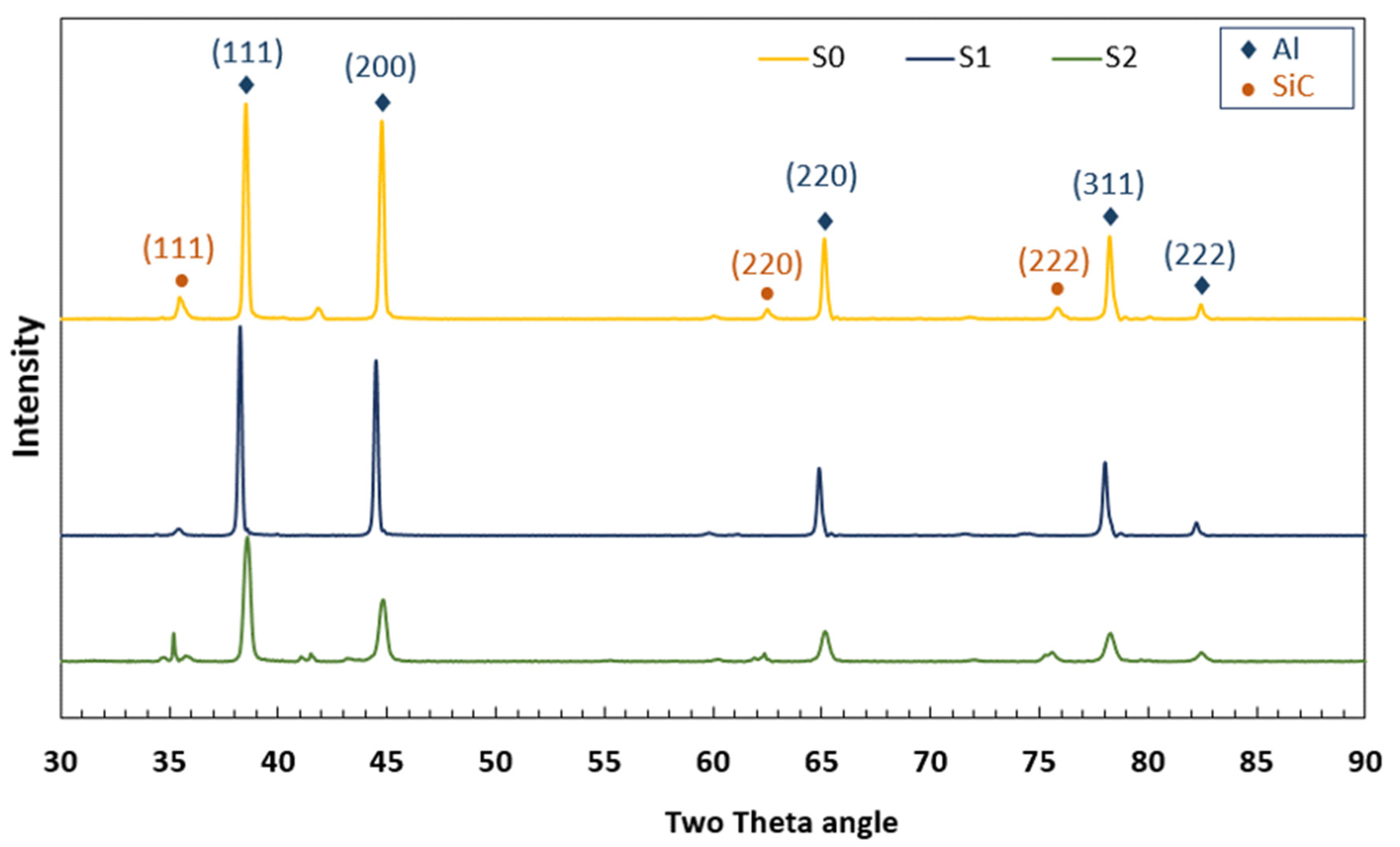
3.2. X-ray Diffraction Analysis

XRD analysis can be utilized to examine the existence of SiC in the bulk nanocomposites. Therefore, the XRD patterns of the bulk nanocomposites produced by the different three tracks in this study are presented in Figure 4. The SiC peaks can be recognized from these XRD patterns which can confirm the presence of SiC and the uniform distribution of this reinforcement in all samples. This, in fact, is predictable because all the three strategies are effective relying on the preparation of Al flakes at the starting phase. The Al flakes have the ability of accommodating the reinforcement nanoparticles. The uniform distribution of SiC nanoparticles between Al flaky particles take place when the starting speed is low. The following stages of the process in all these strategies has no unfavorable effect on the achieved homogeneity owing to the sophisticated design of these strategies to sustain the benefits of flake powder metallurgy.
Additionally, the S0 sample shows a lower broadening in comparison with that of the rest of the samples, denoting that the larger crystallite size of this sample in comparison with the other samples. Furthermore, the S1 nanocomposite shows a lower diminishing in the intensity of Al peak compared to the other nanocomposites, which suggests that the dislocation density is higher than of that of the other samples. Moreover, in the S1 sample, the peak of the SiC is more obvious than that on the other samples confirming the relatively higher agglomeration as stated earlier.
The pattern of the S2 sample is different from those in S0 and S1, which have a mostly diminished peak accompanied by the highest broadening, suggesting a smaller crystallite size associated with the highest microstrain among all the produced nanocomposites. This confirms the usefulness of this last strategy in the restriction of the grain growth and the prevention of dislocation movement, ensuing an enhanced mechanical property as will be presented later.

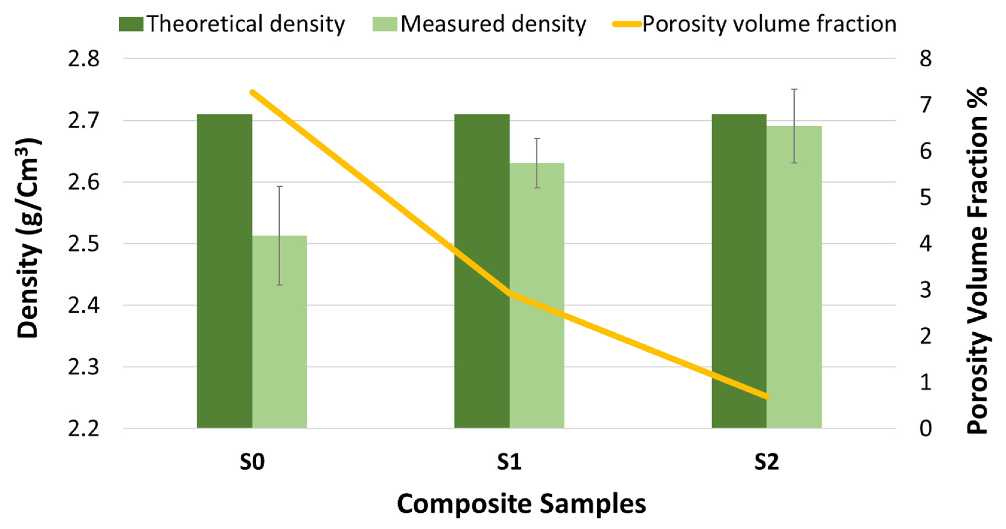
3.3. Density and Porosity

The density and porosity are important measures of the effectiveness of the consolidation process. Thus, Figure 5 presents theoretical and measured densities in addition to the porosity fraction. It can be seen that the highest difference between the theoretical and measured density is in the S0 sample. The reason behind this can be a result of the lower ball milling time of the strategy used to produce this sample. This lower ball milling time resulted in particles with larger size and flake shapes. The flake shape particles usually have lower packing ability and the lower ball milling time may lead to a lower densification rate as stated in [62]. This means that this sample has a lower relative density and a higher porosity fraction in comparison to the other samples. Nevertheless, the lowest difference between theoretical and measured densities can be seen in the S2 sample. This resulted in a high relative density and lower porosity fraction confirming the efficacy of the manufacturing strategy used to produce the S2 sample in generating particles with an appropriate shape for the consolidation process.

4. Mechanical Properties

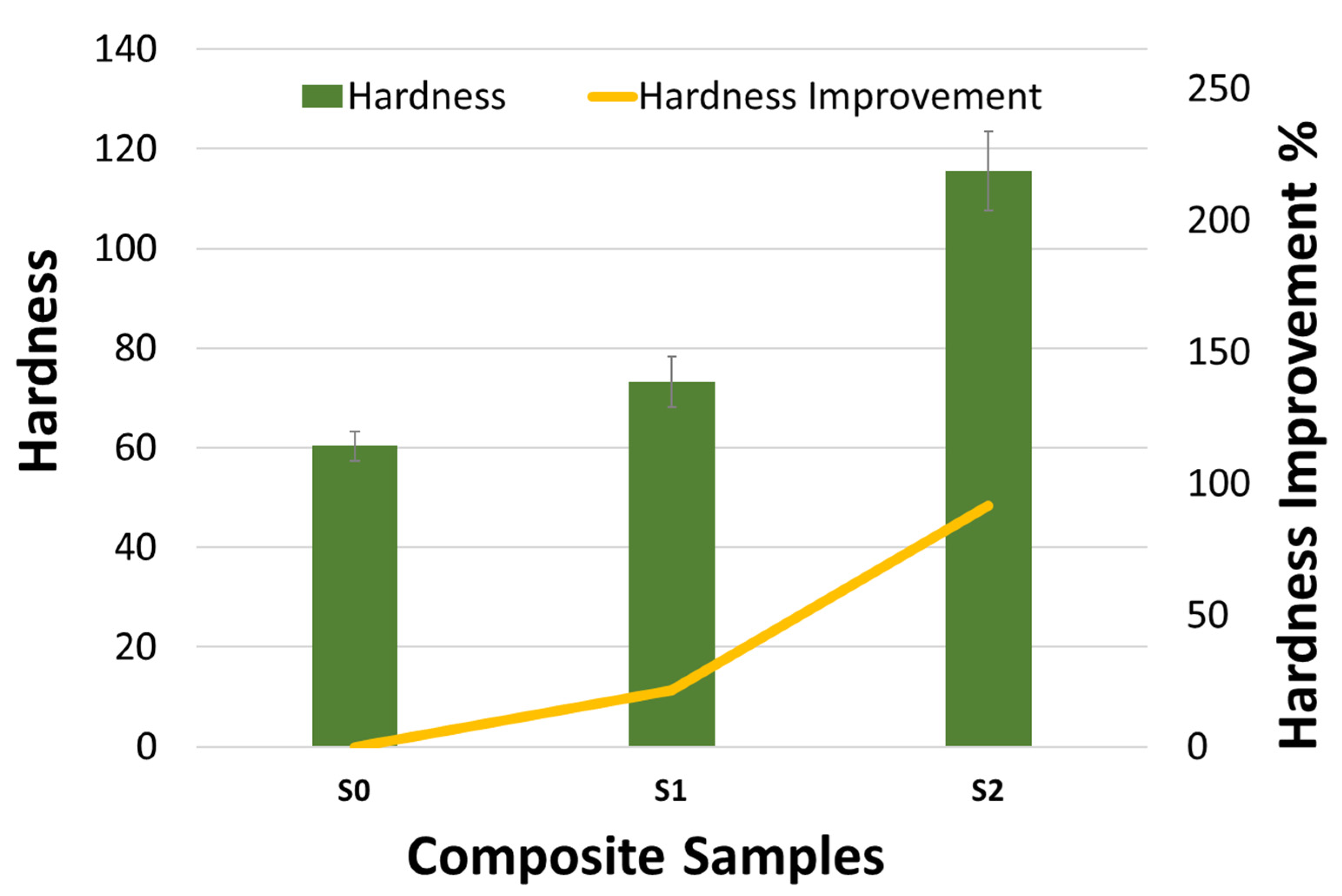
4.1. Hardness Results

Microhardness of the produced bulk composites were obtained by averaging 5 readings for each sample. The average readings for S0, S1, and S2 were 60, 73, and 115 HV5kN, respectively. These results of the microhardness are presented in Figure 6.
It can be seen from this figure the clear effect of the implemented strategies on the obtained microhardness results. Among the three nanocomposites, the lowest hardness is for S0 sample. This result can be ascribed to the lower ball milling time used in this strategy in comparison to the other two strategies. In contrast, the S1 nanocomposite has a slightly boosted hardness due to the extra ball milling. This extra ball milling was for a short time utilizing low speed. However, its effect is noticeable. Moreover, the massive enhancement in hardness is seen in the S2 nanocomposite. The hardness of S2 is sharply increased and showed improvement percentages of 56% and 91 % higher than that of S1 and S0, correspondingly. This can be endorsed to the distinctive design of the manufacturing process for this nanocomposite, utilizing the advantages of flake powder metallurgy, employing the shifting speed, and achieving the steady state in powder synthesis. This novel technique is an advancement in ball milling combining a very good interfacial bonding of the Al/SiC, a uniform distribution of SiC nanoparticles within the Al matrix, and a task allocation for SiC nanoparticles to block the motion of dislocations.

4.2. Compression Test

Compression test allows for insight into different mechanical properties of the tested samples. Thus, compression test was employed on the produced nanocomposites. The result of the test was used to obtain Young’s modulus and the compressive yield strength as shown in Figure 7. They were also used to obtain shrinkage in length and toughness as presented in Figure 8.
Investigation of the results presented in Figure 7 shows that the Young’s modulus values are nearly similar for all produced nanocomposites confirming the ability of all these nanocomposites to bear almost a comparable load in the elastic zone. However, the compressive yield strength of S0 and S1 are very close while the excellent result is seen in the S2 nanocomposite reaching a 470 MPa value of compressive yield strength. This showed that the route utilized to produce this nanocomposite has resulted in a superior mechanical property due to its sophisticated design in synthesizing the powder.
Further analysis of the mechanical properties can be obtained from Figure 8 which presents the shrinkage in length and toughness extracted from the compression test results. The shrinkage percentages have minor differences with a high shrinkage percentage in S0 attributed to the low milling time preserving the base matrix ductility. Nevertheless, the optimum values of both shrinkage percentage and toughness are seen in S2. This is again confirming the high capability of the strategy used in producing this nanocomposite. In fact, it can be stated that the optimum values of all mechanical properties are seen in this S2 sample including Young’s modulus and yield strength as presented in Figure 7 and shrinkage and toughness as presented in Figure 8.
This unmatched result can be accredited to the sophisticated procedure followed in this route. This procedure started with milling at a lower speed, allowing for controlled preparation of particles with flake shape and uniform distribution of the reinforcement particles. The next step in this procedure is shifting the milling speed to benefit from the higher compressive force that is able to laminate part of the broken Al particles on the outer surface of the big particles which will allow maintaining of the uniform distribution of the reinforcement. This is followed by another shifting to an even higher milling speed resulting in adequately bonding the particles of the base matrix and reinforcement and reaching the steady state for the ball milling process.

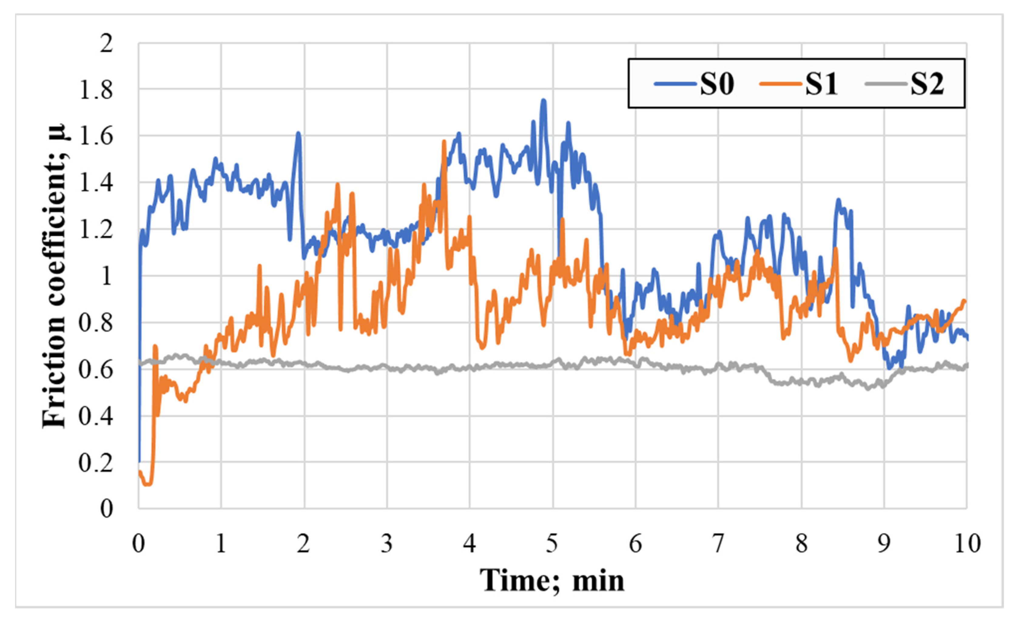
4.3. Tribological Performance

The tribological behavior of the material is another important aspect. To understand the tribological behavior of the produced nanocomposites, the samples were scoured against stainless steel in a rotational movement at 100 rpm while a constant load of 10 N is applied to them. The test was conducted for 5, 10 min duration. For a 10 min test, a real time variation of the friction coefficient was recorded and presented in Figure 9.
It is obvious that the friction coefficient is decreasing with increasing of the time in all samples. However, the change in the friction coefficient in S2 is ultimately low in comparison with that of the other samples. Additionally, its value in this sample is the lowest. This result also confirmed the beneficial effect of the processing route of this sample in obtaining good tribological behavior.
Additionally, the specific wear rate for all samples in both tests is presented in Figure 10. Both test results showed that the specific wear rate of S2 is very low in comparison to the other two nanocomposites produced in this study. This is attributed to the superiority of the nanocomposites produced utilizing the S2 strategy. These results can be added to the finding of mechanical properties making the S2 the novel nanocomposite produced in this study.

5. Conclusions

Three different strategies were designed and implemented to produce three different nanocomposites by reinforcing 2 wt.% of SiC into Al matrix. The following different conclusions were drawn during this study:
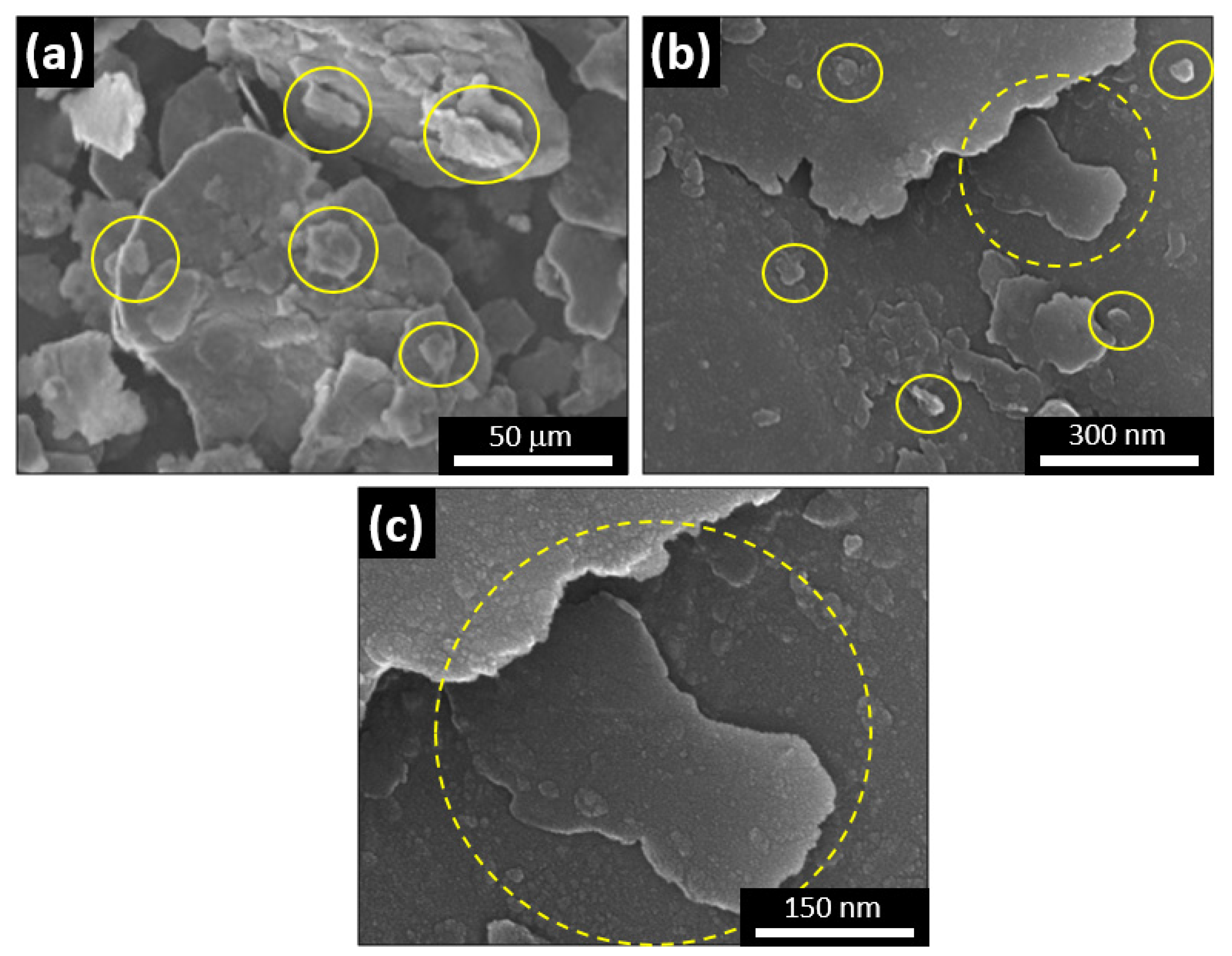
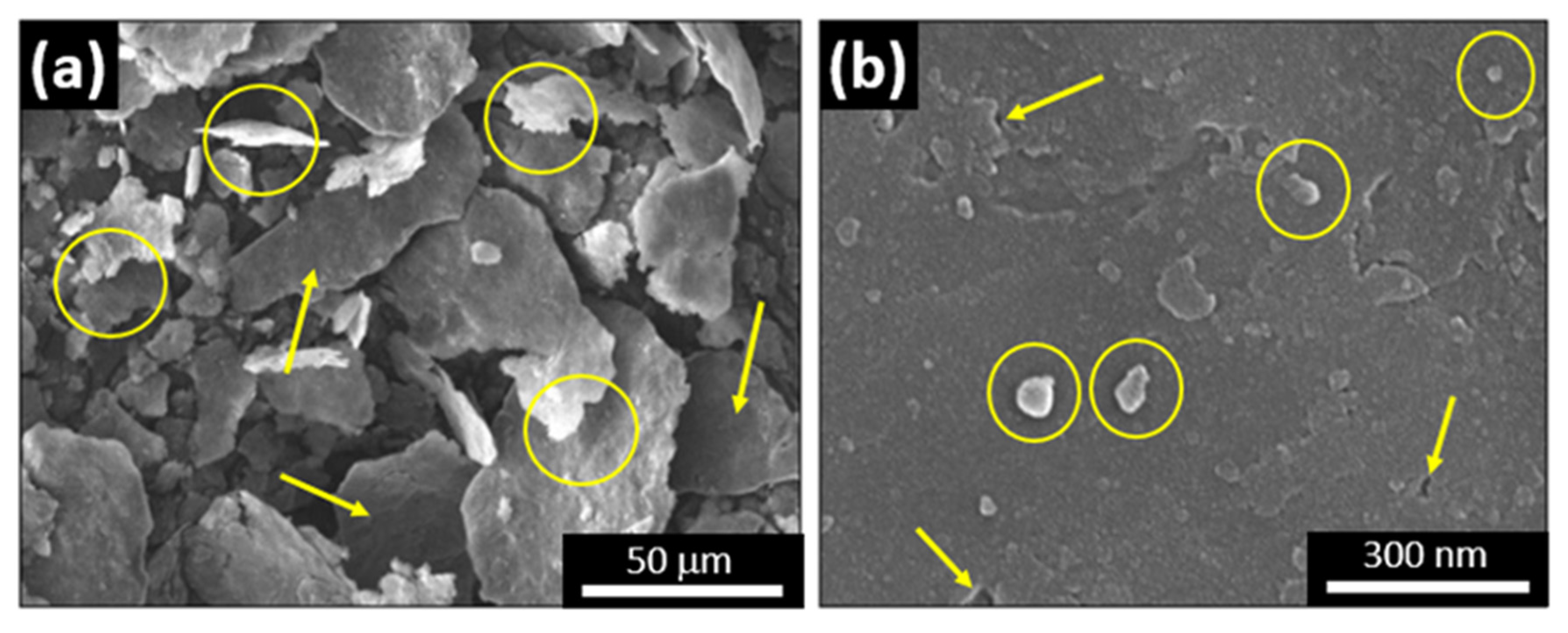
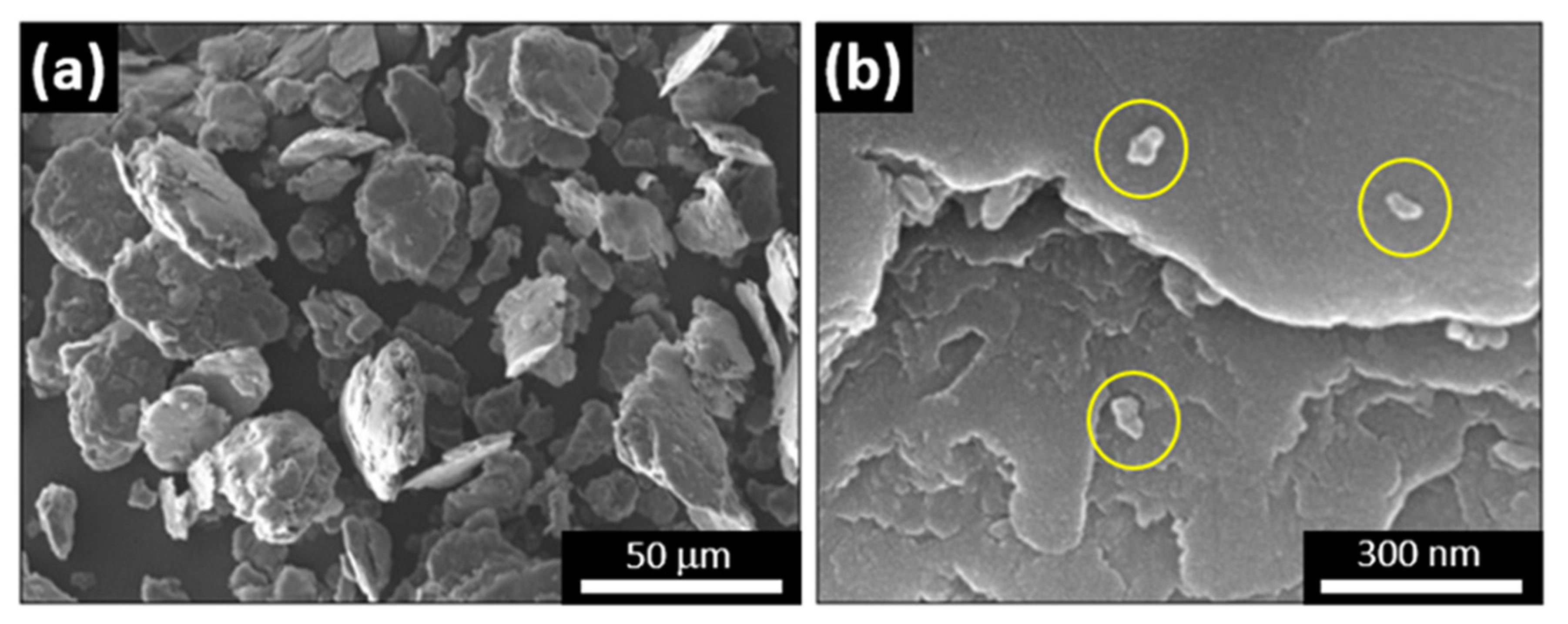
  • The FE-SEM images and the analysis of the synthesized powder have explained the morphological evolution during each ball milling route utilized in this work. This has showed that starting the milling process at low speed can assure the conversion of the spherical particles of the base matrix into flaky ones. These flaky shapes particles have the ability to accommodate the reinforcement nanoparticles in the following stages. Additionally, this showed that increasing the milling speed will allow for the homogeneity of the reinforcement within the matrix. Moreover, increasing the ball milling speed even further will allow for good bonding.
  • It has been found that utilizing different ball milling speeds can produce a different phenomenon. At the beginning of the ball milling process, a low speed is favorable and can be used to control the particle shape and distribute the reinforcement uniformly. Higher speed allows for maintaining the homogeneity of the powder. Additionally, increasing the ball milling speed further will help in achieving a steady state in the powder.
  • A low-cost sustainable material with a 115 hardness, a compressive yield strength of 470 MPa, Young’s modulus of 80 GPa, good ductility, high toughness, coefficient of friction of 0.6, and low specific wear rate was fabricated by utilizing a well-designed novel flake powder metallurgy route.
  • If the designed strategy is capable to reach the steady state between fracturing and rewelding, then the produced powder will result in a nanocomposite with superior mechanical and tribological properties.
This study has shown that utilizing three speeds resulted in a nanocomposite material with optimized mechanical properties including Young’s modulus, yield strength, elongation, and toughness., in addition, having a low friction coefficient and low specific wear rate.

Author Contributions

Conceptualization, S.M.A. and N.H.A.; methodology, S.M.A. and A.M.A.; validation, A.M.A. and S.M.A.; formal analysis, S.M.A. and A.M.A.; investigation, S.M.A. and A.M.A.; resources, N.H.A.; data curation, S.M.A. and N.H.A.; writing—original draft preparation, S.M.A.; writing—review and editing, S.M.A. and A.M.A.; supervision, N.H.A.; project administration, N.H.A.; funding acquisition, N.H.A. All authors have read and agreed to the published version of the manuscript.

Funding

This work is funded by the College of Engineering Research Center, Deanship of Scientific Research at King Saud University, Riyadh, Saudi Arabia.

Institutional Review Board Statement

Not applicable.

Informed Consent Statement

Not applicable.

Data Availability Statement

Not applicable.

Acknowledgments

The corresponding author extends appreciation to the RDO-MOE Postdoctoral Fellowship Program (PFP).

Conflicts of Interest

The authors declare no conflict of interest.

References

  1. Kaczmar, J.W.; Pietrzak, K.; Włosiński, W. The production and application of metal matrix composite materials. J. Mater. Process. Technol. 2000, 106, 58–67. [Google Scholar] [CrossRef]
  2. Wang, Z.; Song, M.; Sun, C.; Xiao, D.; He, Y. Effect of extrusion and particle volume fraction on the mechanical properties of SiC reinforced Al–Cu alloy composites. Mater. Sci. Eng. 2010, 527, 6537–6542. [Google Scholar] [CrossRef]
  3. Prasad, S.V.; Asthana, R. Aluminum Metal–Matrix Composites for Automotive Applications: Tribological Considerations. Tribol. Lett. 2004, 17, 445–453. [Google Scholar] [CrossRef]
  4. Ajagol, P.; Anjan, B.N.; Marigoudar, R.N.; Preetham Kumar, G.V. Effect of SiC Reinforcement on Microstructure and Mechanical Properties of Aluminum Metal Matrix Composite. In IOP Conference Series: Materials Science and Engineering; IOP Publishing: Bristol, UK, 2018; Volume 376, p. 012057. [Google Scholar]
  5. Kumar, P.A.; Rohatgi, P.; Weiss, D. 50 Years of Foundry-Produced Metal Matrix Composites and Future Opportunities. Int. J. Met. 2020, 14, 291–317. [Google Scholar]
  6. Zhang, X. Regulation of interface between carbon nanotubes-aluminum and its strengthening effect in CNTs reinforced aluminum matrix nanocomposites. Carbon 2019, 155, 686–696. [Google Scholar] [CrossRef]
  7. Din, R.U.; Shafqat, Q.A.; Asghar, Z.; Zahid, G.H.; Basit, A.; Qureshi, A.H.; Manzoor, T.; Nasir, M.A.; Mehmood, F.; Hussain, K.I. Microstructural Evolution, Powder Characteristics, Compaction Behavior and Sinterability of Al 6061–B4C Composites as a Function of Reinforcement Content and Milling Times. Russ. J. Non-Ferr. Met. 2018, 59, 207–222. [Google Scholar] [CrossRef]
  8. Thandalam, S.K.; Ramanathan, S.; Sundarrajan, S. Synthesis, microstructural and mechanical properties of ex situ zircon particles (ZrSiO4) reinforced Metal Matrix Composites (MMCs): A review. J. Mater. Res. Technol. 2015, 4, 333–347. [Google Scholar] [CrossRef] [Green Version]
  9. Faisal, N.; Kumar, K. Mechanical and tribological behaviour of nano scaled silicon carbide reinforced aluminium composites. J. Exp. Nanosci. 2018, 13 (Suppl. 1), S1–S13. [Google Scholar] [CrossRef]
  10. Varol, T.; Canakci, A. Synthesis and characterization of nanocrystalline Al 2024–B4C composite powders by mechanical alloying. Philos. Mag. Lett. 2013, 93, 339–345. [Google Scholar] [CrossRef]
  11. Tjong, S.C. Recent progress in the development and properties of novel metal matrix nanocomposites reinforced with carbon nanotubes and graphene nanosheets. Mater. Sci. Engin. Rep. 2013, 74, 281–350. [Google Scholar] [CrossRef]
  12. Lu, L.; Lai, M.O.; Ng, C.W. Enhanced mechanical properties of an Al based metal matrix composite prepared using mechanical alloying. Mater. Sci. Eng. 1998, 252, 203–211. [Google Scholar] [CrossRef]
  13. Lütjering, G.; Williams, J.C. Titanium Matrix Composites. In Titanium; Springer: Berlin/Heidelberg, Germany, 2007; pp. 367–382. [Google Scholar]
  14. Miller, M.K.; Parish, C.M.; Li, Q. Advanced oxide dispersion strengthened and nanostructured ferritic alloys. Mater. Sci. Technol. 2013, 29, 1174–1178. [Google Scholar] [CrossRef]
  15. AlHazaa, A.; Haneklaus, N. Diffusion Bonding and Transient Liquid Phase (TLP) Bonding of Type 304 and 316 Austenitic Stainless Steel—A Review of Similar and Dissimilar Material Joints. Metals 2020, 10, 613. [Google Scholar] [CrossRef]
  16. Selvakumar, N.; Gnanasundarajayaraja, B.; Rajeshkumar, P. Enhancing the Properties of Al–WC Nanocomposites Using Liquid Metallurgy. Exp. Tech. 2016, 40, 129–135. [Google Scholar] [CrossRef]
  17. Liu, J.; Chen, Z.; Zhang, F.; Ji, G.; Wang, M.; Ma, Y.; Ji, V.; Zhong, S.; Wu, Y.; Wang, H. Simultaneously increasing strength and ductility of nanoparticles reinforced Al composites via accumulative orthogonal extrusion process. Mater. Res. Lett. 2018, 6, 406–412. [Google Scholar] [CrossRef] [Green Version]
  18. Ramasubramanian, K.; Arunachalam, N.; Rao, M.S.R. Wear performance of nano-engineered boron doped graded layer CVD diamond coated cutting tool for machining of Al-SiC MMC. Wear 2019, 426, 1536–1547. [Google Scholar] [CrossRef]
  19. Marimuthu, S.; Dunleavey, J.; Liu, Y.; Smith, B.; Kiely, A.; Antar, M. Characteristics of hole formation during laser drilling of SiC reinforced aluminium metal matrix composites. J. Mater. Process. Technol. 2019, 271, 554–567. [Google Scholar] [CrossRef]
  20. Singh, N.; Mir, I.U.H.; Raina, A.; Anand, A.; Kumar, V.; Sharma, S.M. Synthesis and tribological investigation of Al-SiC based nano hybrid composite. Alex. Eng. J. 2018, 57, 1323–1330. [Google Scholar] [CrossRef]
  21. Akbari, M.K.; Rajabi, S.; Shirvanimoghaddam, K.; Baharvandi, H.R. Wear and friction behavior of nanosized TiB2 and TiO2 particle-reinforced casting A356 aluminum nanocomposites: A comparative study focusing on particle capture in matrix. J. Compos. Mater. 2015, 49, 3665–3681. [Google Scholar] [CrossRef]
  22. Almotairy, S.M.; Boostani, A.F.; Hassani, M.; Wei, D.; Jiang, Z.Y. Mechanical Properties of Aluminium Metal Matrix Nanocomposites Manufactured by Assisted-Flake Powder Thixoforming Process. Met. Mater. Int. 2021, 27, 851–859. [Google Scholar] [CrossRef]
  23. Akbari, M.K.; Baharvandi, H.R.; Shirvanimoghaddam, K. Tensile and fracture behavior of nano/micro TiB2 particle reinforced casting A356 aluminum alloy composites. Mater. Des. 2015, 66, 150–161. [Google Scholar] [CrossRef]
  24. Tjong, S.C. Novel Nanoparticle-Reinforced Metal Matrix Composites with Enhanced Mechanical Properties. Adv. Eng. Mater. 2007, 9, 639–652. [Google Scholar] [CrossRef]
  25. Grácio, J.J.; Picu, C.R.; Vincze, G.; Mathew, N.; Schubert, T.; Lopes, A.; Buchheim, C. Mechanical Behavior of Al-SiC Nanocomposites Produced by Ball Milling and Spark Plasma Sintering. Metall. Mater. Trans. A 2013, 44, 5259–5269. [Google Scholar] [CrossRef]
  26. Zhang, Z.; Chen, D.L. Contribution of Orowan strengthening effect in particulate-reinforced metal matrix nanocomposites. Mater. Sci. Eng. 2008, 483, 148–152. [Google Scholar] [CrossRef]
  27. Fan, T.; Xiao, C.L.; Sun, Y.R.; Li, H.B. Microstructure and Properties of SiC Particle Reinforced Aluminum Matrix Composites by Powder Metallurgy Method. Appl. Mech. Mater. 2014, 457, 131–134. [Google Scholar] [CrossRef]
  28. Liu, S.; Yuan, Q.; Sima, Y.; Liu, C.; Han, F.; Qiao, W. Wear behavior of Zn–38Al–3.5Cu–1.2Mg/SiCp composite under different stabilization treatments. Int. J. Miner. Metall. Mater. 2022, 1–10. [Google Scholar] [CrossRef]
  29. Taherzadeh Mousavian, R.; Behnamfard, S.; Heidarzadeh, A.; Taherkhani, K.; Azari Khosroshahi, R.; Brabazon, D. Incorporation of SiC Ceramic Nanoparticles into the Aluminum Matrix by a Novel Method: Production of a Metal Matrix Composite. Met. Mater. Int. 2021, 27, 2968–2976. [Google Scholar] [CrossRef]
  30. Fathy, A.; Sadoun, A.; Abdelhameed, M. Effect of matrix/reinforcement particle size ratio (PSR) on the mechanical properties of extruded Al–SiC composites. Int. J. Adv. Manuf. Technol. 2014, 73, 1049–1056. [Google Scholar] [CrossRef]
  31. Reddy, M.P.; Shakoor, R.A.; Parande, G.; Manakari, V.; Ubaid, F.; Mohamed, A.M.A.; Gupta, M. Enhanced performance of nano-sized SiC reinforced Al metal matrix nanocomposites synthesized through microwave sintering and hot extrusion techniques. Prog. Nat. Sci. Mater. Int. 2017, 27, 606–614. [Google Scholar] [CrossRef]
  32. Hashim, J.; Looney, L.; Hashmi, M.S.J. Metal matrix composites: Production by the stir casting method. J. Mater. Process. Technol. 1999, 92–93, 1–7. [Google Scholar] [CrossRef]
  33. Dey, D.; Chintada, S.K.; Bhowmik, A.; Biswas, A. Evaluation of wear performance of Al2024-SiC ex-situ composites. Mater. Today: Proc. 2020, 26, 2996–2999. [Google Scholar] [CrossRef]
  34. Liu, S.; Yuan, Q.; Gong, Y.; Xu, G.; Qiau, W. Relationship between microstructure and dry wear behavior of compo-cast nano-SiC(p) + micro-Gr(p)/Zn-35Al-1.2Mg-0.2Sr composite under different chilling conditions. Met. Mater. 2020, 58, 49–57. [Google Scholar] [CrossRef]
  35. Akbarpour, M.R.; Pouresmaeil, A. The influence of CNTs on the microstructure and strength of Al-CNT composites produced by flake powder metallurgy and hot pressing method. Diam. Relat. Mater. 2018, 88, 6–11. [Google Scholar] [CrossRef]
  36. Kai, X.Z.; Li, Z.Q.; Fan, G.L.; Guo, Q.; Xiong, D.B.; Zhang, W.L.; Su, Y.S.; Lu, W.J.; Moon, W.J.; Zhang, D. Enhanced strength and ductility in particulate-reinforced aluminum matrix composites fabricated by flake powder metallurgy. Mater. Sci. Eng. 2013, 587, 46–53. [Google Scholar] [CrossRef]
  37. Khan, A.S.; Farrokh, B.; Takacs, L. Effect of grain refinement on mechanical properties of ball-milled bulk aluminum. Mater. Sci. Eng. 2008, 489, 77–84. [Google Scholar] [CrossRef]
  38. Fan, G.; Xu, R.; Tan, Z.; Zhang, D.; Li, Z. Development of Flake Powder Metallurgy in Fabricating Metal Matrix Composites: A Review. Acta Metall. Sin. 2014, 27, 806–815. [Google Scholar] [CrossRef] [Green Version]
  39. Vani, V.V.; Chak, S.K. The effect of process parameters in Aluminum Metal Matrix Composites with Powder Metallurgy. Manuf. Rev. 2018, 5, 7. [Google Scholar] [CrossRef] [Green Version]
  40. Carvalho, O.; Buciumeanu, M.; Soares, D.; Silva, F.S.; Miranda, G. Evaluation of CNT Dispersion Methodology Effect on Mechanical Properties of an AlSi Composite. J. Mater. Eng. Perform. 2015, 24, 2535–2545. [Google Scholar] [CrossRef]
  41. Tan, M.J.; Zhang, X. Powder metal matrix composites: Selection and processing. Mater. Sci. Eng. 1998, 244, 80–85. [Google Scholar] [CrossRef]
  42. Nishida, Y. Introduction to Metal Matrix Composites: Fabrication and Recycling; Springer: Tokyo, Japan, 2013. [Google Scholar]
  43. Sabirov, I.; Kolednik, O.; Valiev, R.Z.; Pippan, R. Equal channel angular pressing of metal matrix composites: Effect on particle distribution and fracture toughness. Acta Mater. 2005, 53, 4919–4930. [Google Scholar] [CrossRef]
  44. Kai, X.Z.; Li, Z.Q.; Zhang, W.L.; Fan, G.L.; Jiang, L.; Lu, W.J.; Zhang, D. A model for volume fraction and/or particle size selection in metal matrix composites. Mater. Sci. Eng. 2011, 530, 574–579. [Google Scholar] [CrossRef]
  45. Lee, I.S.; Hsu, C.J.; Chen, C.F.; Ho, N.J.; Kao, P.W. Particle-reinforced aluminum matrix composites produced from powder mixtures via friction stir processing. Compos. Sci. Technol. 2011, 71, 693–698. [Google Scholar] [CrossRef]
  46. Morsi, K.; Esawi, A. Effect of mechanical alloying time and carbon nanotube (CNT) content on the evolution of aluminum (Al)–CNT composite powders. J. Mater. Sci. 2007, 42, 4954–4959. [Google Scholar] [CrossRef]
  47. Hesabi, Z.R.; Hafizpour, H.R.; Simchi, A. An investigation on the compressibility of aluminum/nano-alumina composite powder prepared by blending and mechanical milling. Mater. Sci. Eng. 2007, 454, 89–98. [Google Scholar] [CrossRef]
  48. Jiang, L.; Li, Z.; Fan, G.; Zhang, D. A flake powder metallurgy approach to Al2O3/Al biomimetic nanolaminated composites with enhanced ductility. Scr. Mater. 2011, 65, 412–415. [Google Scholar] [CrossRef]
  49. Jiang, L.; Li, Z.; Fan, G.; Cao, L.; Zhang, D. The use of flake powder metallurgy to produce carbon nanotube (CNT)/aluminum composites with a homogenous CNT distribution. Carbon 2012, 50, 1993–1998. [Google Scholar] [CrossRef]
  50. Kai, X.; Li, Z.; Fan, G.; Guo, Q.; Tan, Z.; Zhang, W.; Su, Y.; Lu, W.; Moon, W.-J.; Zhang, D. Strong and ductile particulate reinforced ultrafine-grained metallic composites fabricated by flake powder metallurgy. Scr. Mater. 2013, 68, 555–558. [Google Scholar] [CrossRef]
  51. Wei, H.; Li, Z.; Xiong, D.-B.; Tan, Z.; Fan, G.; Qin, Z.; Zhang, D. Towards strong and stiff carbon nanotube-reinforced high-strength aluminum alloy composites through a microlaminated architecture design. Scr. Mater. 2014, 75, 30–33. [Google Scholar] [CrossRef]
  52. Varol, T.; Canakci, A. The effect of type and ratio of reinforcement on the synthesis and characterization Cu-based nanocomposites by flake powder metallurgy. J. Alloys Compd. 2015, 649, 1066–1074. [Google Scholar] [CrossRef]
  53. Rikhtegar, F.; Shabestari, S.G.; Saghafian, H. The homogenizing of carbon nanotube dispersion in aluminium matrix nanocomposite using flake powder metallurgy and ball milling methods. Powder Technol. 2015, 280, 26–34. [Google Scholar] [CrossRef]
  54. Luan, B.-F.; Qiu, R.-S.; Li, C.-H.; Yang, X.-F.; Li, Z.-Q.; Zhang, D.; Liu, Q. Hot deformation and processing maps of Al2O3/Al composites fabricated by flake powder metallurgy. Trans. Nonferrous Metals Soc. China 2015, 25, 1056–1063. [Google Scholar] [CrossRef]
  55. He, W.-J.; Li, C.-H.; Luan, B.-F.; Qiu, R.-S.; Wang, K.; Li, Z.-Q.; Liu, Q. Deformation behaviors and processing maps of CNTs/Al alloy composite fabricated by flake powder metallurgy. Trans. Nonferrous Metals Soc. China 2015, 25, 3578–3584. [Google Scholar] [CrossRef]
  56. Canakci, A.; Varol, T.; Erdemir, F. The Effect of Flake Powder Metallurgy on the Microstructure and Densification Behavior of B4C Nanoparticle-Reinforced Al–Cu–Mg Alloy Matrix Nanocomposites. Arabian J. Sci. Eng. 2016, 41, 1781–1796. [Google Scholar] [CrossRef]
  57. Xu, R.; Tan, Z.; Xiong, D.; Fan, G.; Guo, Q.; Zhang, J.; Su, Y.; Li, Z.; Zhang, D. Balanced strength and ductility in CNT/Al composites achieved by flake powder metallurgy via shift-speed ball milling. Compos. A Appl. Sci. Manuf. 2017, 96, 57–66. [Google Scholar] [CrossRef]
  58. Chen, M.; Fan, G.; Tan, Z.; Xiong, D.; Guo, Q.; Su, Y.; Zhang, J.; Li, Z.; Naito, M.; Zhang, D. Design of an efficient flake powder metallurgy route to fabricate CNT/6061Al composites. Mater. Des. 2018, 142, 288–296. [Google Scholar] [CrossRef]
  59. Jiang, Y.; Tan, Z.; Xu, R.; Fan, G.; Xiong, D.-B.; Guo, Q.; Su, Y.; Li, Z.; Zhang, D. Tailoring the structure and mechanical properties of graphene nanosheet/aluminum composites by flake powder metallurgy via shift-speed ball milling. Compos. A Appl. Sci. Manuf. 2018, 111, 73–82. [Google Scholar] [CrossRef]
  60. Okoro, A.M.; Machaka, R.; Lephuthing, S.S.; Awotunde, M.A.; Oke, S.R.; Falodun, O.E.; Olubambi, P.A. Dispersion characteristics, interfacial bonding and nanostructural evolution of MWCNT in Ti6Al4V powders prepared by shift speed ball milling technique. J. Alloys Compd. 2019, 785, 356–366. [Google Scholar] [CrossRef]
  61. Burmeister, C.F.; Kwade, A. Process engineering with planetary ball mills. Chem. Soc. Rev. 2013, 42, 7660–7667. [Google Scholar] [CrossRef] [PubMed]
  62. Toozandehjani, M.; Matori, K.A.; Ostovan, F.; Abdul Aziz, S.; Mamat, M.S. Effect of Milling Time on the Microstructure, Physical and Mechanical Properties of Al-Al2O3 Nanocomposite Synthesized by Ball Milling and Powder Metallurgy. Materials 2017, 10, 1232. [Google Scholar] [CrossRef] [Green Version]
Figure 1. Morphology of the powder synthesized using a milling process at two speeds (S0 route). (a) 10 k, (b) 50 k and (c) 100 k magnification. Circles around the small particles laminated on the top of the large particles in (a) and around the clusters of SiC in (b).
Metals 12 00323 g001
Figure 2. Morphology of the powder synthesized using milling process at three speeds (S1 route). (a) 10 k, (b) 50 k magnification. Circles around the edge of particles where they are very smooth in (a) and around the clusters of SiC in (b). Arrows pointing to the removal of laminated particles in (a) and cavities in (b).
Metals 12 00323 g002
Figure 3. Morphology of the powder synthesized using milling process at three speeds (S2 route). (a) 10 k, (b) 50 k magnification. Circles around the clusters of SiC in (b).
Metals 12 00323 g003
Figure 4. XRD patterns of the ball milled nanocomposites.
Metals 12 00323 g004
Figure 5. Densities and porosity of the bulk nanocomposites.
Metals 12 00323 g005
Figure 6. Hardness results of the produced nanocomposites.
Metals 12 00323 g006
Figure 7. Young’s Modulus and compressive yield strength.
Metals 12 00323 g007
Figure 8. Shrinkage in length and toughness of the produced nanocomposites.
Metals 12 00323 g008
Figure 9. The real-time friction coefficient of the nanocomposites under a 10 N load.
Metals 12 00323 g009
Figure 10. Specific wear rate of the nanocomposites under 10 N load.
Metals 12 00323 g010
Table 1. Summary of processing routes.
RoutePhase 1Phase 2Phase 3
S0150 rpm (8 h)300 rpm (4 h)------
S1150 rpm (8 h)300 rpm (4 h)150 rpm (2 h)
S2150 rpm (8 h)300 rpm (4 h)450 rpm (1 h)
Publisher’s Note: MDPI stays neutral with regard to jurisdictional claims in published maps and institutional affiliations.

