Article

Surface Hardening Behavior of Advanced Gear Steel C61 by a Novel Solid-Solution Carburizing Process

1
Institute of Special Steels, Central Iron and Steel Research Institute, Beijing 100081, China
2
Unit of 32381 People’s Liberation Army, Beijing 100081, China
*
Author to whom correspondence should be addressed.
Metals 2022, 12(3), 379; https://doi.org/10.3390/met12030379
Submission received: 15 January 2022 / Revised: 15 February 2022 / Accepted: 15 February 2022 / Published: 23 February 2022

Abstract

:
During vacuum carburizing, coarse reticulated carbides tend to precipitate along grain boundaries due to high-carbon-potential conditions. This phenomenon is often one of the main factors in the failure of conventional gear steels. In this paper, a novel solid-solution carburizing process was proposed to achieve nano-carbide formation in the surface of the carburizing layer, and the conventional carburizing process and material thermodynamic calculations were combined to study the carburized layer by changing the parameters of the carburizing process, and to optimize the microstructure and properties of the carburized layer. The results showed that the high carbon potential or the long-time boost carburizing process could easily cause the enrichment of many carbon atoms in the traditional carburization, thus forming a carbide network and decreasing the carburization efficiency. The minor increase in large-sized M7C3 carbides did not significantly improve the surface hardness and wear resistance. However, the presence of small and dispersed M2C carbides was the main factor in improving the microhardness and mechanical properties. The novel solid-solution carburizing process could improve the carburizing efficiency and transform reticulated carbides into nano-dispersed M2C carbides. The surface carbon content and microhardness of 1.07% and 875 HV, respectively, increased 17.7 and 2.4% compared to conventional carburizing processes at 1100 °C. On the other hand, the surface’s ultimate tensile strength was found to be 1900 MPa by mini-tensile testing, and the core had a good match of strength and toughness. It was concluded that the novel solid-solution carburizing process could dissolve the carbon network and thus effectively increase the surface carbon content, achieving fully nanosized carbide on the surface. Modifying the size, morphology, and distribution of the nano-M2C carbides dispersed within the lath-martensite after tempering the test steel was found to be the main factor in improving the mechanical properties.

1. Introduction

The aero-engine is the heart of the aircraft and is a highly complex and precise system. The transmission gear of the main engine shaft is a key component that needs to be subjected to multiple complex stresses, strains, fatigue, and wears under the combined effect of high temperature and a high-speed environment [1,2,3,4,5]. As engine performance and reliability requirements increase, there is a significant need for innovation in a new generation of aerospace gear steel. Currently, the traditional heat treatment process can no longer meet the growing performance needs of the aerospace industry. Advanced surface modification technologies need to be applied to enhance surface wear resistance and fatigue life effectively [6,7,8]. At the same time, the core has high strength and toughness characteristics to suit the various needs in gears and transmissions, and other devices.
Researchers and scholars have been greatly interested vacuum carburizing since its emergence [7,9,10]. Comparatively, other surface treatment technologies may have abrupt changes in their microstructure and properties between the coating and the surface. While the vacuum carburizing process can make its microstructure change with depth, the surface hardening layer can behave as a functional gradient material. The high-temperature vacuum carburizing process can effectively improve its comprehensive mechanical properties. There is no oxidation and decarburization behavior in the carburizing and quenching process [11]. The carburizing layer is more uniform, the deformation after quenching can be negligible, and the production process is less expensive [12].
During high-temperature vacuum carburization, the process parameters such as carburizing temperature, time, and carbon potential greatly affect the microstructure and properties. Wang et al. studied the vacuum carburizing process and found that prolonged boost carburizing will lead to a severe carbon concentration excess and carbon blackening [10,13,14,15,16]. In the conventional vacuum carburizing process, carbon atoms cannot diffuse from the surface to the core area in sufficient time, due to the high carbon potential environment [17]. This phenomenon leads to an enormous enrichment in carbon atoms on the surface of the seepage layer, which easily combines with strong carbide-forming elements such as Cr and Mo, thus forming coarse reticulated carbides and solid carbon layers, challenging to eliminate in the subsequent heat treatment process [18,19]. The diffusion rate of elements such as C and Cr along with grain boundaries is 102~103 times faster than the diffusion rate within the grain boundaries; and its diffusion rate within the grain boundaries is lower than the growth of grains, which is the reason why secondary carbides precipitate and form network carbides at the grain boundaries. Thus, the generation of such coarse carbides hinders the fast diffusion channel of carbon atoms, reducing the carburizing efficiency [20]. In recent years, a large number of scholars have found that a re-austenitizing quenching process is used in order to eliminate reticulated carbides. However, the multiple quenching process tends to generate large thermal and structural stresses, which increase the tendency of deformation and cracking of the workpiece. The study by An et al. found that the formation of reticulated carbides could be suppressed by adjusting process parameters such as carburizing temperature, time, and carbon potential [21]. A mathematical model including time and temperature variables was developed to predict the critical volume fraction of carbon formation, and its critical carbon concentration can be further calculated by this thermodynamic simulation calculation, which enables the prediction of web carbons.
Compared to this coarse reticulated carbide, the smaller and more dispersed carbide particles contribute to the strength of the alloy, and the presence of such diffuse second-phase particles strengthens the matrix [3,22]. It has been found that for contact fatigue performance, dispersed carbide has the best fatigue life, the intermittent reticulated carbide carburizing level is second-best, and the little or no carbide performance is worst; and the intermittent reticulated carbide life dispersion is the largest and most unstable. The presence of dispersed carbide can be 1~2 HRC (Rockwell hardness) higher than conventional carburized steel, with better wear resistance, and the longer the wear time, the more its superiority is revealed, and the contact fatigue life is nearly 20 times higher than that of carbide-free specimens [23,24,25,26].
In this paper, based on the conventional carburizing process and thermodynamic calculations, a novel solid-solution carburizing process is designed for the transformation of coarse reticulated carbides to nanoscale-dispersed carbides in order to achieve the full nanosized surface carbides, to improve their comprehensive performance, and to maintain the strong toughness of the core microstructure matching. Therefore, it is necessary to investigate the surface hardening behavior of advanced gear steels during the novel solid-solution carburizing process.

2. Materials and Methods

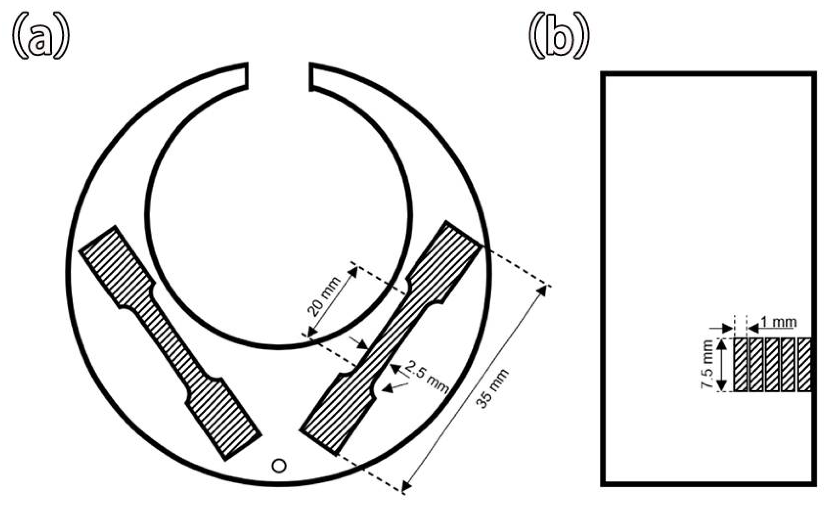
2.1. Experimental Materials and Methods

The C61 (AEROSPACE MATERIAL SPECIFICATION 6517 [2,4,5]) gear steel studied in this paper was melted by the vacuum induction melting and self-consumption remelting (Vacuum induction melting + Vacuum Arc Remelting) process and forged into Φ75 mm bars after high-temperature homogenization. Its main chemical composition is shown in Table 1. In addition, 20 mm × 20 mm × 15 mm square, Φ30 × 100 mm round bar, and C-ring samples (only in the new solid-solution carburizing process) were cut from the forged bar, using the WZST-45 vacuum carburizing quenching furnace (Beijing Research Institute of Mechanical & Electrical Technology, Beijing, China) for boost carburizing + diffusion multi-stage cyclic pulse carburizing treatment. The conventional vacuum carburizing process is shown in Figure 1a, using a mixed carburizing atmosphere made of acetylene and nitrogen at 1000/1100 °C for low-pressure vacuum pulse carburizing, a boost carburizing stage to control its equivalent carbon potential of 1.3%, a carburizing pressure of 300 Pa, a diffusion stage to control its equivalent carbon potential of 0.9%, and a carburizing pressure of 70 Pa, after three cycles of strong carburizing + diffusion, in the furnace for oil quenching. After cooling to room temperature, the specimens were deep-cooled at −196 °C for 1 h using liquid nitrogen as the cooling medium, and then finally tempered at 482 °C for 16 h after the samples returned to room temperature. Such processes were named as process L1, L2, L3, and L4, as shown in Table 2. Figure 1b depicts the novel solid-solution carburizing process, named process N, which elevates the carburizing temperature in the final diffusion stage and can effectively eliminate the reticulated carbides without the need for re-quenching to retreat the carbides, saving the time and cost of process production.

2.2. Performance Testing and Observation

After the carburizing and subsequent heat treatment process, the specimens were cut in half along the longitudinal plane; smoothed and polished with 60, 150, 320, 600, and 1000 mesh; and then etched with 4% nitric acid alcohol. The microstructure of the carburized layer was observed using an Olympus GX51 optical microscope (Olympus, Japan) and a Quanta 650 field emission scanning electron microscope (FEI Company, Hillsboro, American), and the Shimadzu EPMA-1720H instrument (Shimadzu, Japan) was used to analyze the distribution of each element by electron probe (EPMA) surface scanning. To prepare TEM samples, the sample thickness was reduced to 50 μm using mechanical polishing. The electrolytic solution was 6% (by volume) perchloric acid ethanol solution for electrolytic double spraying. The polishing temperature was −25 °C, the polishing voltage was 38 V, the current was 55 mA, and the microstructure of the carburized layer was analyzed by a Talos F200X transmission electron microscope (FEI Company, Hillsboro, American).
The X-ray diffraction specimens were 10 mm × 10 mm × 5 mm after electrolytic polishing, the carburized surface layers of samples with different carburizing processes were analyzed by a PHILIPS PD-10 X-ray diffractometer (Philips, Japan) (Co target, 30 kV voltage, 30 mA current, and scanning 20–115 °C), and the austenite content in the specimens was calculated according to Chinese national standard GB/T 8362-1987.
The iron chips were obtained by turning layer by layer on the carburized round bar at a depth of 0.1 mm per layer to measure their carbon content at different carburization depths using a Combustion Master CS carbon and sulfur analyzer (NCS Testing Technology GmbH, Neuss, Germany). Using an FM-300 digital microscope hardness tester (FUTURE- TECH Corp., Kawasaki, Japan), (load of 500 gf), points were taken vertically along the edge of the specimen at 100 μm intervals. The microhardness of 3 points per carburizing depth was measured and averaged to obtain the microhardness curve of the carburizing layer.
Mini-tensile specimens were fabricated from the C-carburized specimens shown in Figure 2, and two small-size tensile parallel specimens were removed at 1 mm intervals from the carburized surface to reduce the experimental error. Hand grinding processing was applied to the standard specimen and the error was controlled to 0.02 mm. Using an Instron 5565 tensile tester (Instron, Shanghai, China), mini-tensile specimens were tested at a strain rate of 0.0005/s, and the elongation and area shrinkage of the specimens were recorded during the experiment.

3. Results and Discussion

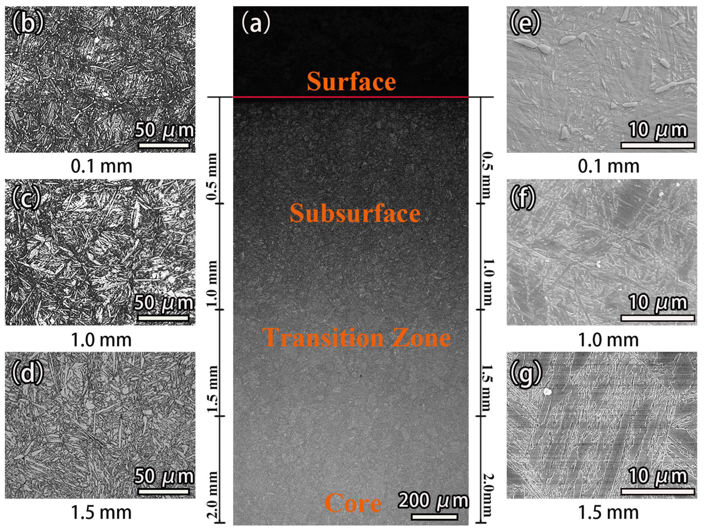
3.1. Microstructure of the Carburized Layer

The vacuum carburizing process will cause the microstructure of the test steel to change with the change in depth of the carburizing layer. Therefore, the microstructure evolution of the carburized layer under process L2 was observed by optical microscopy (OM) and scanning electron microscopy (SEM). Obviously, the microstructure gradually changed from the surface layer to the core area of the specimen, as shown in Figure 3a. After carburization, the specimen could be divided into three regions: the surface layer, the transition zone, and the core zone. Figure 3b,e show the morphology of the carburized surface layer at 0.1 mm, mainly characterized by the high-carbon needle-like martensite accompanied by the precipitation of carbide along with the grain boundary of block austenite remaining between the martensite. With the change in depth of the carburizing layer, the precipitation of carbide in the transition zone reduced, and the needle-like martensite transformed into lath-martensite. When the carburizing layer of 1.5 mm was reached at the heart of the specimen, the high-carbon acicular martensite disappeared, and the lamellar martensite showed a directional bundle arrangement, as shown in Figure 3d,g. The study of the carburizing process can effectively regulate the carbon content gradient in the carburizing process, which has a crucial impact on the matching of the C61 carburized steel properties.

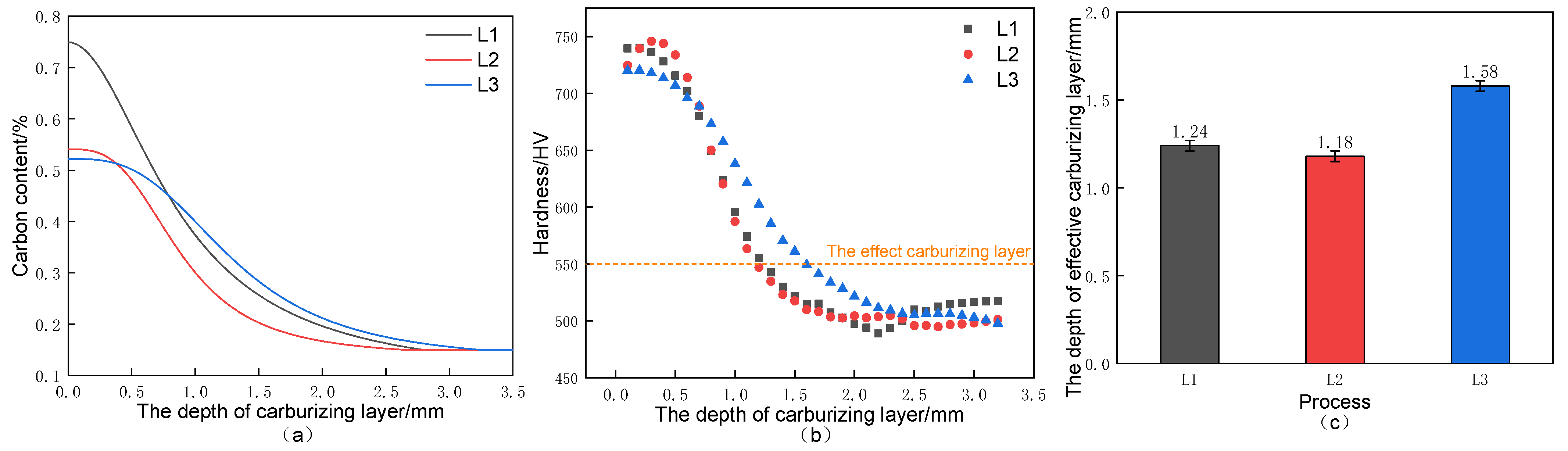
3.2. Carbon Concentration Gradient and Hardness Distribution

To investigate the effect of different boost carburizing/diffusion times on the carbon content under the vacuum carburizing condition at 1000 °C, the carbon content variation curves were measured using a carbon and sulfur analyzer, as shown in Figure 4a. The carburized surface layer was the highest point of carbon concentration, and the carbon concentration showed a gradual decrease with the increase in carburizing depth. Process L1 with a boost carburizing time of 30 min had the best carbon concentration curve, and the surface carbon content reached 0.75%. In contrast, for process L2, with a constant total carburizing time, when the boost carburizing time was increased to 60 min, the increase in the boost carburizing time reduced the surface carbon concentration to only 0.56%, and the depth of the carburized layer was also smaller than that in process L1. The diffusion time was extended to 420 min in the L3 process so that the carbon atoms on the surface had sufficient time to diffuse to the core of the specimen, and the carbon concentration gradient was smoother, which significantly increased the carburization depth and stabilized the carbon content to 0.15% at about 3 mm from the surface. However, the extension of diffusion time did not effectively increase the surface carbon content, and the surface carbon content did not change much to 0.54%.
The microhardness curve, Figure 4b, was basically consistent with the trend of the carbon content curve; with the increase in the carburizing depth, the microhardness value showed an overall decreasing trend, and finally, the microhardness value of the core was stabilized at about 500 HV. At the boost carburizing time of 30 min, the highest carbon content on the surface of L1 corresponded to its microhardness value of 740 HV. The effective carburization layer is defined as the vertical distance from the surface to the depth of 550 HV on the Vickers hardness according to the Chinese national standard GB/T 9450-2005. Its effective carburization layer depth was 1.24 mm. The carbon atoms enriched on the surface at the boost carburizing stage were enough to form a more significant carbon content gradient, which made the surface layer of carbon atoms transfer to the interior of the material, which not only made the surface carbon content higher but also effectively increased the carburization layer depth. However, too long a boost carburizing stage will lead to large-sized reticulated carbides, and solid carbon layers on the surface will hinder the carburization efficiency. This phenomenon can be observed in process L2, and the surface hardness decreased compared with process L1. Its hardness peak also shifted to the right, showing a trend of first increasing and then decreasing. The microhardness reached a maximum value of 745 HV at the carburization layer depth of 0.3 mm instead, and the effective carburization layer depth was 1.17 mm. The hardness curve was smoother with the extension of diffusion time in process L3, and the maximum effective carburizing depth reached 1.58 mm. Still, the surface hardness did not increase significantly to 720 HV.

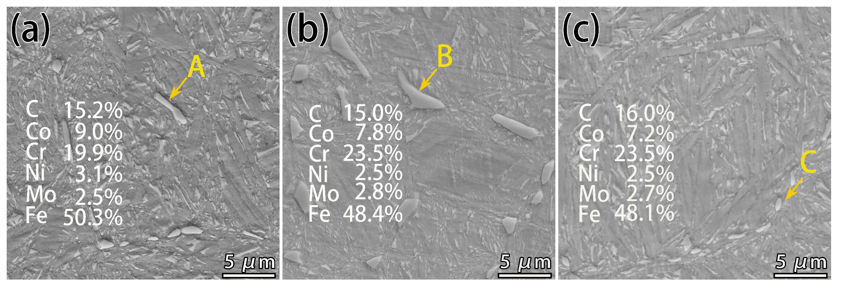
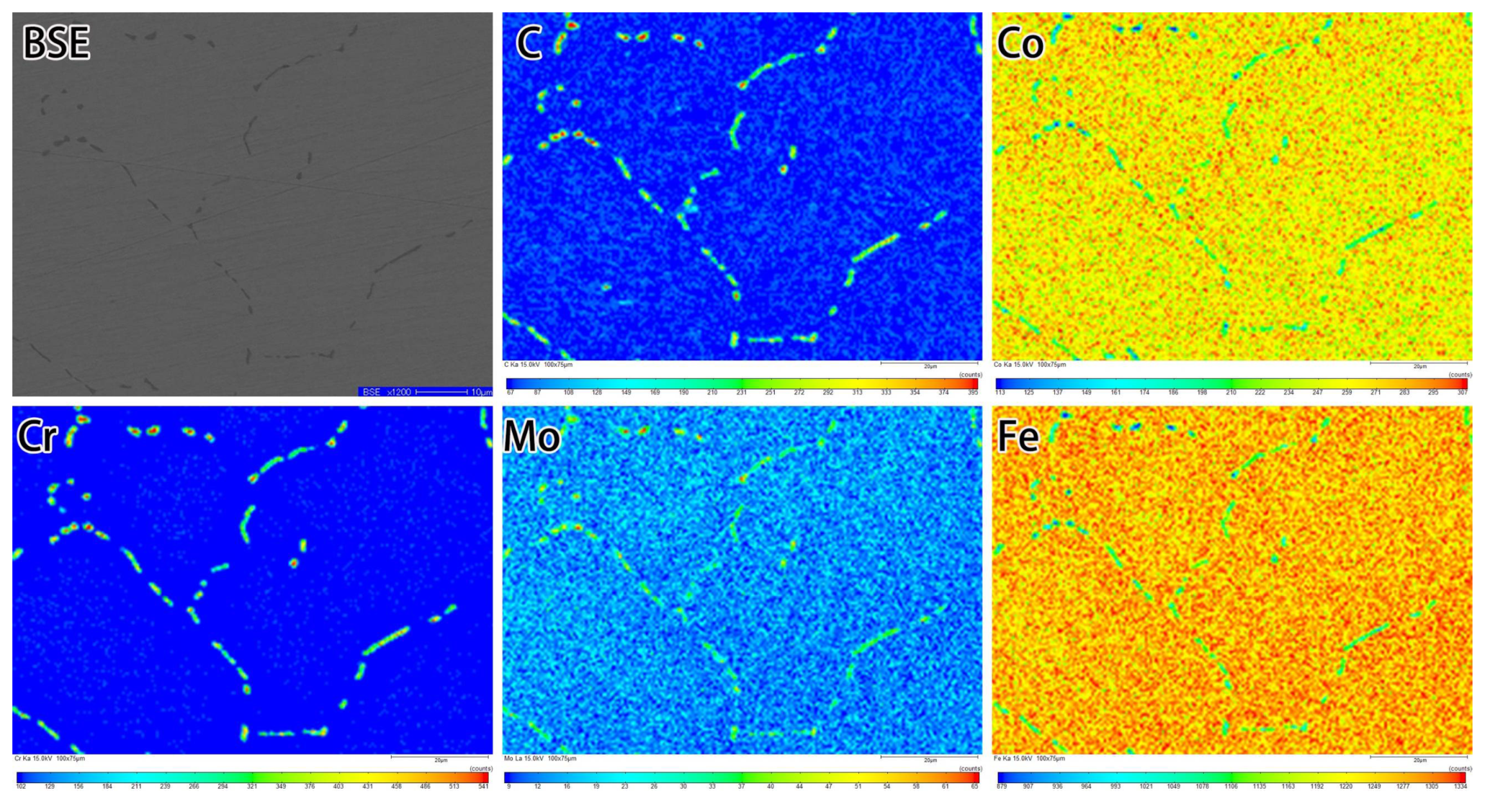
3.3. Formation of Network Carbides during the Conventional Carburizing Process

Under the high-temperature vacuum carburizing condition at 1000 °C, the microstructure of the surface layer of the specimen was observed by different boost carburizing/diffusion times, as shown in Figure 5. Many carbides were found to precipitate along the prior austenite grain boundaries at 0.1 mm of the carburizing layer under processes L1, L2, and L3 using SEM. According to the Energy Dispersive Spectroscopy (EDS) at points A, B, and C, the atomic ratio of alloying elements to carbon elements was close to 7:3, and the precipitated phase was presumed to be a Cr-rich M7C3 carbide. Figure 6 shows the Electron Microprobe (EPMA) mapping analysis performed on the carbide-enriched area to analyze this along-grain carbide further. The backscattering electron (BSE) images and alloying element sweep profiles of C61 steel in process L2 showed the carbide-forming elements, which easily form carbides and expel other elements from their carbide positions [27]. Cr elements were less abundant within the grain boundaries, while Mo elements and C elements remained in a diffuse distribution, indicating the presence of dispersed Mo-rich carbides within the lath-martensitic. Such large-sized precipitated phases affected the mechanical properties such as wear resistance and hardness of the test steel and impacted the carburization efficiency.
An extensive statistical analysis of the M7C3 carbides in the carburized surface layer was performed, as shown in Figure 7. The maximum volume fraction of M7C3 carbides was 4.73% in process L2, and the presence of carbides exceeding 1400 nm was only observed in L2. The excessive duration of intense carburization led to an increase in the volume fraction and size of the precipitated phase but did not increase the carbon concentration and carburization depth. Excess carbon atoms preferentially diffused through the grain boundaries, while combining with strong carbide formed elements such as Cr and Mo to form large-size M7C3 carbides, which hindered the carburizing process to some extent. It is necessary to modify the carbon concentration gradient by adjusting the carburizing process and to then improve the regulation of M7C3 carbides.
The results of XRD data analysis at 0.1 mm of the surface layer for different carburizing process regimes are shown in Figure 8. The matrix organization was found to be mainly martensitic and austenitic, and the martensitic 110 peak was its strongest peak, while the effect of different carburizing processes on the XRD pattern was small. The XRD data were used to calculate the austenite content by the direct comparison method [28], as shown in Table 3. The maximum residual austenite value existed in process L1 due to its maximum carbon content, while carbon atoms were austenite-forming elements, and residual austenite tended to be more stable at higher carbon contents. At low temperatures and low carbon conditions, the phase transformation of residual austenite was more driven [16]. Combined with the empirical equation for the martensitic phase transformation Ms point given by Ishida [29], the calculation results are shown in Table 1. The highest carbon content in process L1 was when the Ms point was lowest at 245.05 °C. The larger the carbon content, the lower the phase transformation point, and the volume fraction of austenite also decreased with the decrease in carbon content. Table 1 shows that although the soft phase austenite was highest in process L1, it still exhibited the highest microhardness value, indicating that the change in hardness of the martensite matrix determined by the carbon content had a much more significant effect on the hardness of the carburized layer than the effect of the transformation of residual austenite to martensite [17,30].

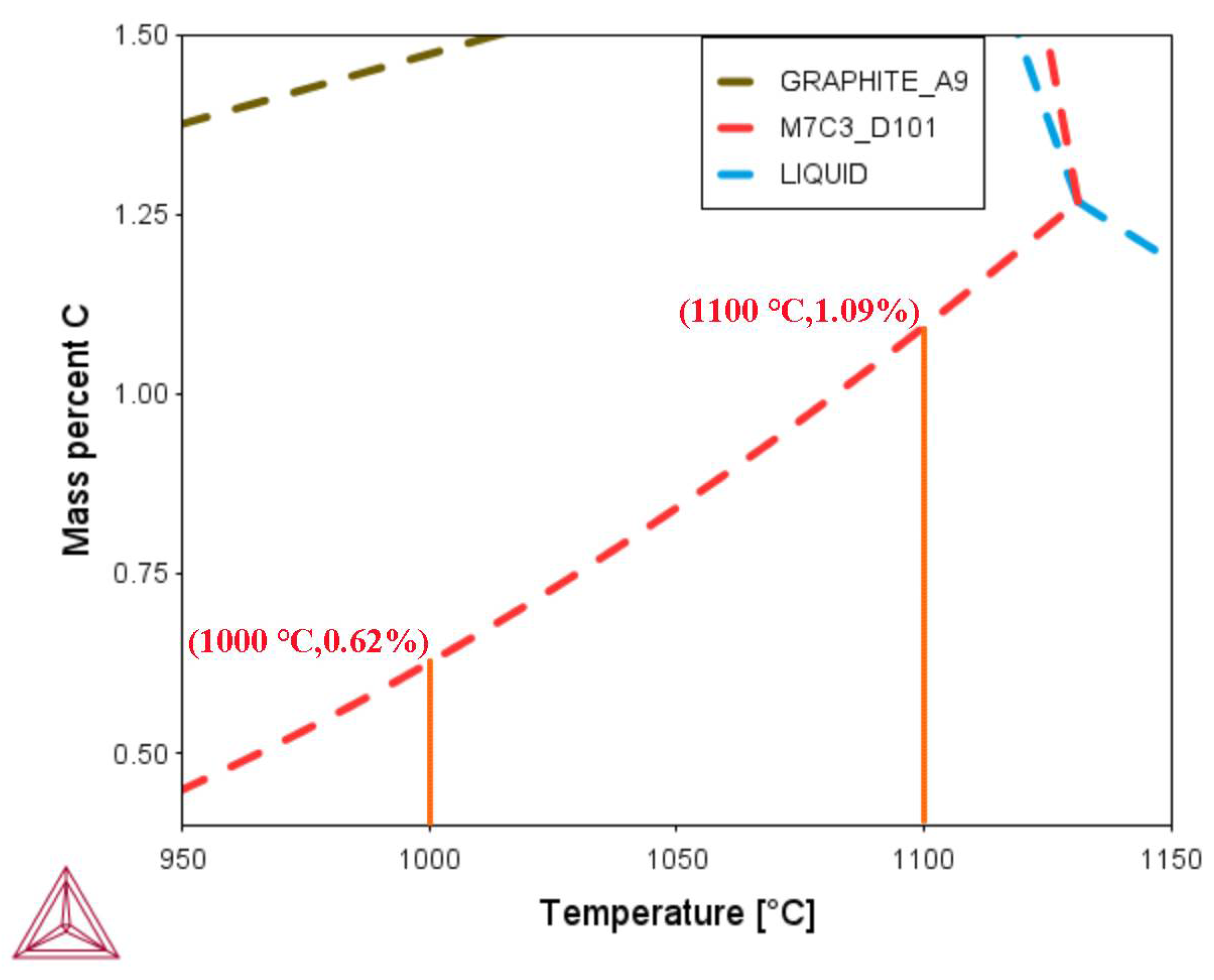
3.4. Effect of Carburizing Temperature during the Conventional Carburizing Process

During the conventional carburizing process, the surface and near-surface regions of the specimen are prone to coarse reticulated carbides distributed along the grain boundaries, which, to a certain extent, disrupt the continuity of the matrix, increasing the brittleness and reducing the fatigue strength of the test steel. On the other hand, in the absence of reticulated carbides, the test steel will have better carburizing efficiency in a high-carbon-potential environment, so preventing the formation of reticulated carbides by adjusting the carburizing process is an effective and low-cost method. According to the literature, the formation conditions of reticulated carbides are related to their saturation carbon content and grain growth behavior. The formation of reticulated carbides can be reasonably suppressed by adjusting the carburizing temperature time and carbon concentration. The results of the thermodynamic calculation software Thermo-Calc (TCEF 10, Thermo-Calc Software, Solna, Sweden) are shown in Figure 9. The increase in carburizing temperature could effectively increase the precipitation point of M7C3 carbide from (1000 °C, 0.62%) to (1100 °C, 1.09%). It could effectively improve the saturated carbon content of martensite, thus reducing the precipitation of reticulated carbides.
When the carburizing temperature was increased to 1100 °C in process L4, the carbon content trend is shown in Figure 10. The carbon content increased significantly, and the surface carbon concentration reached 0.88%, which did not reach the M7C3 carbide precipitation point at this time. The carbon content was not much different from the equivalent carbon potential of 0.9% in the diffusion stage, indicating that it could maintain high efficiency in the carburizing process. In contrast, the coarse along-grains in the carburizing layer in process L2 hindered the carburizing process, resulting in a maximum carbon concentration of 0.54%, which was much lower than the carbon potential in the diffusion stage. However, the surface carbon content was lower than the precipitation point, which indicates that the M7C3 carbides were precipitated at the boost carburizing stage under the carbon potential of 1.3% and could not be ablated during the subsequent heat treatment. Comparing the microhardness values at different carburizing temperatures, the surface hardness of the carburized layer was as high as 854 HV in process L4. In comparison, it was only 740 HV at a carburizing temperature of 1000 °C, and the effective carburized layer was also significantly improved. The higher the carburizing temperature, the higher the diffusion efficiency of carbon elements, and the deeper the effective carburizing layer depth obtained. This indicates that increasing the carburizing temperature in a limited range can improve the surface carbon concentration and microhardness and increase the saturated carbon content, improving the co-precipitation point of M7C3 and effectively eliminating the reticulated carbide.
The carbon content and microhardness accompanied the carburizing temperature. Still, the change in carburizing process will also affect the type of precipitated phase, which will directly affect the tissue properties of the test. To further the evolution of carbides at different carburizing temperatures, the surface layers in processes L2 and L4 were analyzed by TEM. As shown in Figure 11a, precipitates of about 1 μm were observed under process L2, as with the SEM analysis results. Such large-sized carbides had a more significant influence on the carbon diffusion process. As shown in Figure 11b,c, more long strip precipitates were observed between the lath-martensite. Combined with SAED (selected area electron diffraction) map calibration analysis, it was inferred that the long strip carbide at about 200 nm was also M7C3, which followed the following orientation relationship with martensite [ 0 2 ¯ 2 ] M7C3 [ 060 ] M, ( 10 2 ¯ ) M7C3 ( 2 ¯ 11 ) M and ( 202 ) M7C3 ( 0 1 ¯ 1 ) M. According to the comparative observation under the bright- and dark-field phases in Figure 11d,e, the presence of rod-shaped precipitation phases of 10–20 nm size was dispersed through the matrix. Further analyzed by the EDS energy spectrum, the elements of Cr, Mo, and W were much higher than the matrix composition, and all three elements were strong carbide M2C-forming elements. The presence of this precipitated phase is a key factor in improving the structural properties of ultra-high strength steel. This diffuse precipitation was presumed to be (Cr, Mo, and W)2C carbide, and it was in good agreement with the martensite matrix. The orientation of M2C carbide was the same in the whole area, following the following orientation relations [ 2 ¯ 21 ] M2C‖ [ 12 1 ¯ ] M and ( 1 1 ¯ 1 ¯ ) M2C‖ ( 0 1 ¯ 2 ) M. The number and size of M2C were lower, because the main carbon atoms formed aggregates at the grain boundaries, resulting in less secondary precipitation phase during tempering. Elimination of the M7C3 carbide network can provide sufficient carbon atoms for the formation of secondary precipitation phases during tempering.
In the surface layer in process L4, the carbon concentration reached 0.88%. Still, it did not reach the co-precipitation point of M7C3 carbide, and the precipitation of large size along the crystalline carbide was not observed in SEM and TEM. According to the bright- and dark-field phase observation in Figure 12a,b, rod carbides were mainly distributed diffusely within the lath-martensitic. The size of such diffusions was mostly around 20 nm, which was more uniform and diffuse than that of process L2, increasing quantity. EDS surface mapping analysis was performed to further analyze the rod-like precipitates relative to the region in Figure 12c. The corresponding region was mainly Mo- and Cr-aggregated phases. Further, High-Resolution Transmission Electron Microscopy (HRTEM) analysis of this carbide-enriched region was performed to obtain Figure 12d. It was found that the regions shown by yellow and red arrows in the figure had apparent boundaries. The red region observed in magnification, as shown in Figure 12e,g, was obtained by fast Fourier transform (FFT) of the FFT-1 region; the martensitic matrix was Z = [ 2 ¯ 00 ] . M ( 00 2 ¯ ) = 0.1493 nm, belonging to an orthorhombic system, with lattice constants a = b = 0.2754 nm, c = 0.2986 nm, and α = β = γ = 90. The same analysis of the FFT-2 in the yellow arrow region showed that this region was the mixed region of M2C and martensite, as shown in Figure 12i,h, and the lattice spacing d of M2C(110) was 0.1276 nm. Following the orientations [ 001 ] M2C‖ [ 002 ] M, ( 010 ) M2C‖ ( 2 ¯ 01 ) M, and ( 110 ) M2C‖ ( 2 ¯ 00 ) M, it can also be observed that the M2C orientation of the aggregated state under this region had the characteristic of short-range ordering, which indicates that the martensitic matrix maintained a better uniformity. This M2C belonged to the hexagonal crystal system with lattice constants a = b = 0.2994 nm, c = 0.4772 nm, and α = β= 90, γ = 120°.
The surface layer of process L2 under the carburizing condition at 1000 °C was mainly composed of large-sized M7C3 carbides precipitated along the grain boundaries and M2C carbides dispersed in the lath-martensite with a size of about 10 nm. With the increase in carburizing temperature to 1100 °C, along-grain carbides were not observed in the surface layer under process L4. The size of M2C carbides grew to about 20 nm with the increase in carburizing temperature, the dispersion was strong, and most of the M2C carbides in the carbide-enriched area were 5 nm in size in the budding state. The carbides in the ultra-high-strength steel were usually Cr2C, Mo2C, or W2C. M2C carbides were initially nucleated as clusters smaller than 2 nm before they grew into rod or needle carbides of about 20 nm [3,31]. The increase in carburizing temperature effectively eliminated the coarse reticulated carbides. In the process of carburizing with high carbon concentration, the carbon diffusion rate increased significantly, maintaining a high carbon concentration gradient. The trace increase in the volume of M7C3 carbide was not effective in improving the microhardness of the test steel. The increase in carbon content and the size and number of M2C carbides dispersed within the lath-martensite were the main factors in improving its high hardness. Moreover, the dispersed M2C carbides were more beneficial in improving their strength and contact fatigue performance [26].

3.5. Advantages of the Novel Solid-Solution Carburizing Process

Figure 13 compares the fitted images of grain size under different carburizing process conditions, and the Prior Austenite grain sizes were analyzed and counted with OM and Image-Pro Plus 6.0 software, respectively. It was found that the average grain size on the surface was 42 ± 1 μm after carburizing at 1000 °C for 4 h. Due to the smaller grain size, it was easy to form the carbide network, which reduced the carburizing efficiency. When the carburizing temperature was increased to 1100 °C, the grains coarsened during carburizing was noticeable, and the average grain size was about 90 ± 2 μm. Although the carbide network could be eliminated effectively, the larger grain size would affect the strength of the specimen and the strength and toughness matching of the core. Therefore, the novel solid-solution carburizing process was proposed in this paper, which only raised the temperature of the final diffusion stage by 50 °C and effectively reduced the average grain size of the specimen to 68 ± 2 μm, thus ensuring a better match of strength and toughness.
In the novel solid-solution carburization process, as shown in Figure 14a, due to its high carbon potential environmental conditions, the surface carbon atoms gradually enriched and rapidly reached saturation, resulting in the precipitation of the intermittent along-grain carbide network, which, to a certain extent, will cause the carburization efficiency to decrease. Furthermore, the carbides gradually dissolved with the temperature rise in the final diffusion stage due to enriched carbon atoms and an intermittent carbide network. However, the along-crystal quick diffusion channel of carbon atoms was still partially blocked, and the saturation of austenite rose, resulting in the preferential diffusion of sufficient carbon atoms to the inner grain boundaries, as shown in Figure 14b. The carbon content of process N was tested by a carbon and sulfur analyzer. It found that the carbon content with the new solid-solution carburizing process was higher than the surface carbon content at 1100 °C, with a surface carbon concentration of 1.07%. In combination with Thermo-Calc (TCEF 10, Thermo-Calc Software, Solna, Sweden) analysis, Figure 8, it was found that the carbon content was lower than the co-precipitation point of M7C3 carbide, which indicated that there was no presence of carbide along with the crystal at this time, as shown in Figure 14c. Under the conventional carburizing process at 1100 °C, the two stages a and b shown in Figure 14 did not exist; they directly crossed to stage c, where the carbon atoms mainly diffused rapidly along the grain boundaries. The surface carbon atoms were relatively less enriched and could only maintain a deeper carburizing layer depth because the carburizing process was under high-temperature conditions, and there was no precipitation of reticulated carbides.
It was observed in Figure 15b that due to the increase in carbon content on the surface of the novel solid-solution carburizing, the surface hardness also showed a positive correlation and increased to 875 HV, which was 21 HV higher than that of the conventional carburizing process at 1100 °C, and the effective carburizing layer depth also reached 2.4 mm. It was found that the Ultimate Tensile Strength at the surface of the specimens reached 1900 MPa, maintaining high strength and hardness. This was mainly attributed to the full nanosized carbide achieved on the surface, as shown in Figure 16, where the second-phase particles provided high dispersion strengthening, and the increased carbon content maintained a high solid solution strengthening effect. With the depth of the carburized layer, the carbon content, carbide density, and size gradually decreased, the strength of the test steel gradually decreased, and finally, the core region was stabilized at about 1550 MPa; core area A and Z gradually increased to 8 and 25%, respectively. At the same time, the core had a better match of strength and toughness.
The presence of large-sized carbides was not found in the TEM test, and a large number of long needle-like precipitated phases were found inside the lath-martensite, with similar orientation patterns and sizes ranging from 50 to 100 nm, which were analyzed by SAED and EDS, as shown in Figure 16, and found to be probably Cr-rich M2C carbides. Due to the increase in carbon content, the carbide grew compared to the conventional carburization at 1100 °C, showing a long needle-like and dispersed distribution. The novel solid-solution carburizing process effectively dissolved the large carbides along the grain and allowed the preferential diffusion of carbon atoms into the grain boundaries, thus increasing the carbon content in the surface layer. Within the lath-martensite were dispersed nano-M2C carbides, which effectively improved the microhardness and strength of the surface layer. Core A and Z had been significantly enhanced with excellent strong plasticity matching.

4. Conclusions

(1)
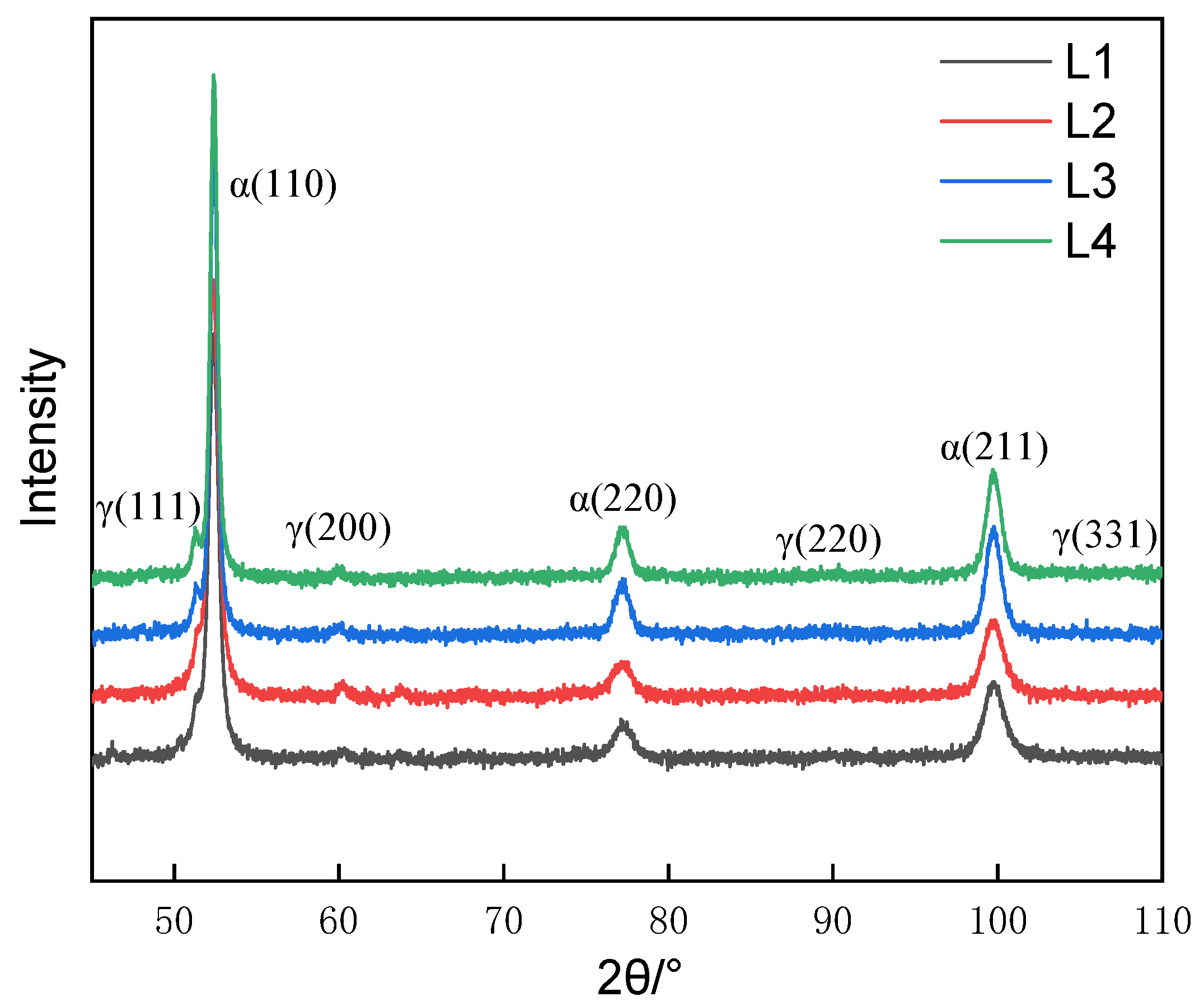
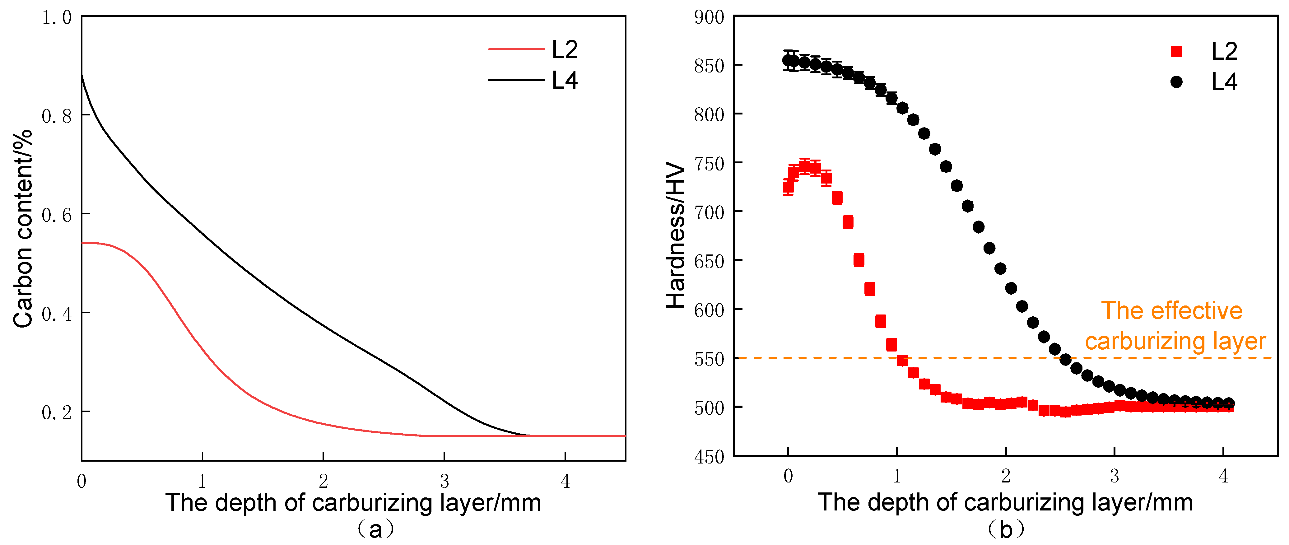
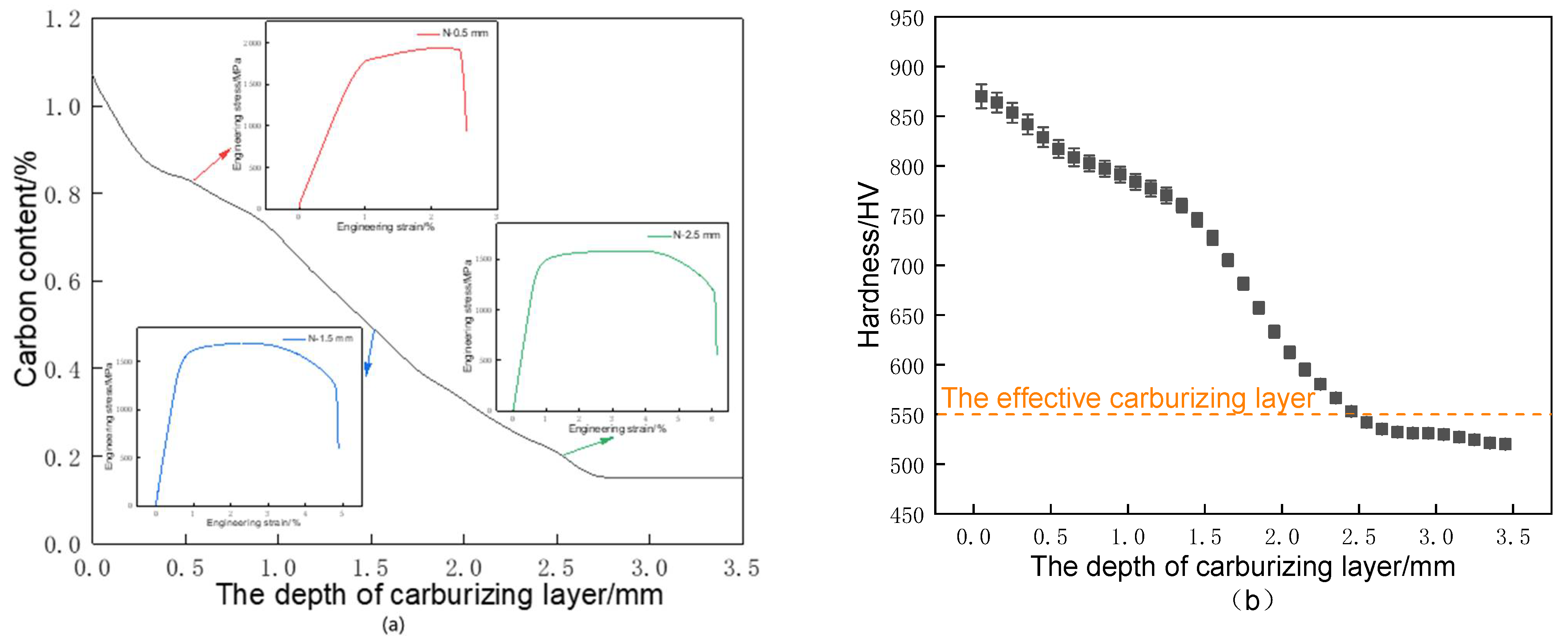
After high-temperature vacuum carburizing heat treatment of C61 steel, the carburized surface layer was mainly high-carbon needle martensite with carbide, while the carbide gradually decreased with the depth of the carburized layer, and the core was mainly low-carbon lath-martensite. Both the carbon concentration and hardness decreased progressively with the depth of the carburized layer and then stabilized.
(2)
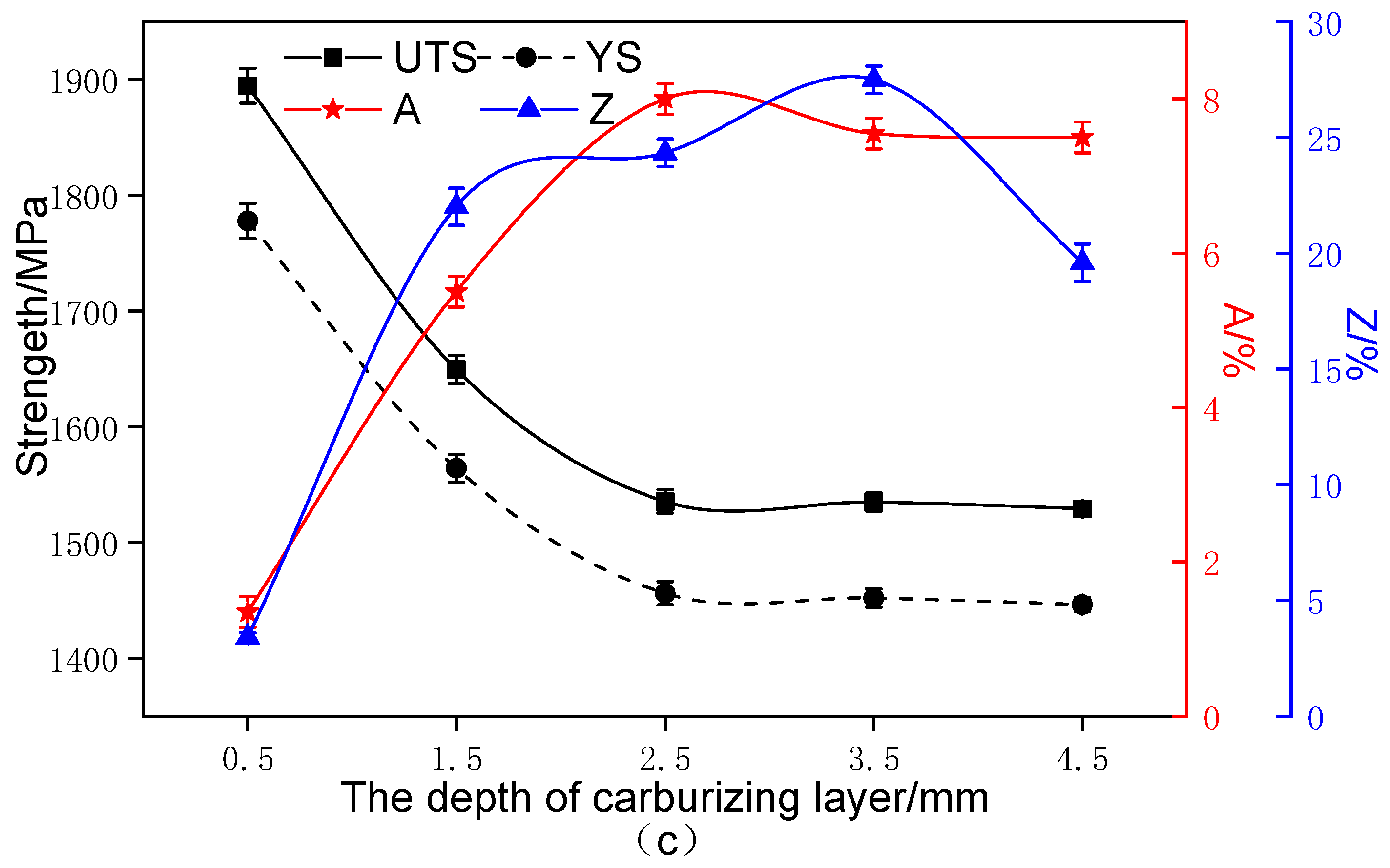
Compared with the conventional carburizing process, the carburized layer’s surface hardness and carbon concentration were significantly increased by the novel solid-solution carburizing process, reaching 875 HV and 1.07%, respectively. The tensile strength of the carburized surface layer was 1900 MPa, and the strength gradually decreased with the depth of the carburized layer, but the plastic toughness gradually increased, and the tensile strength was 1550 MPa in the core region to maintain a better match of strength and toughness.
(3)
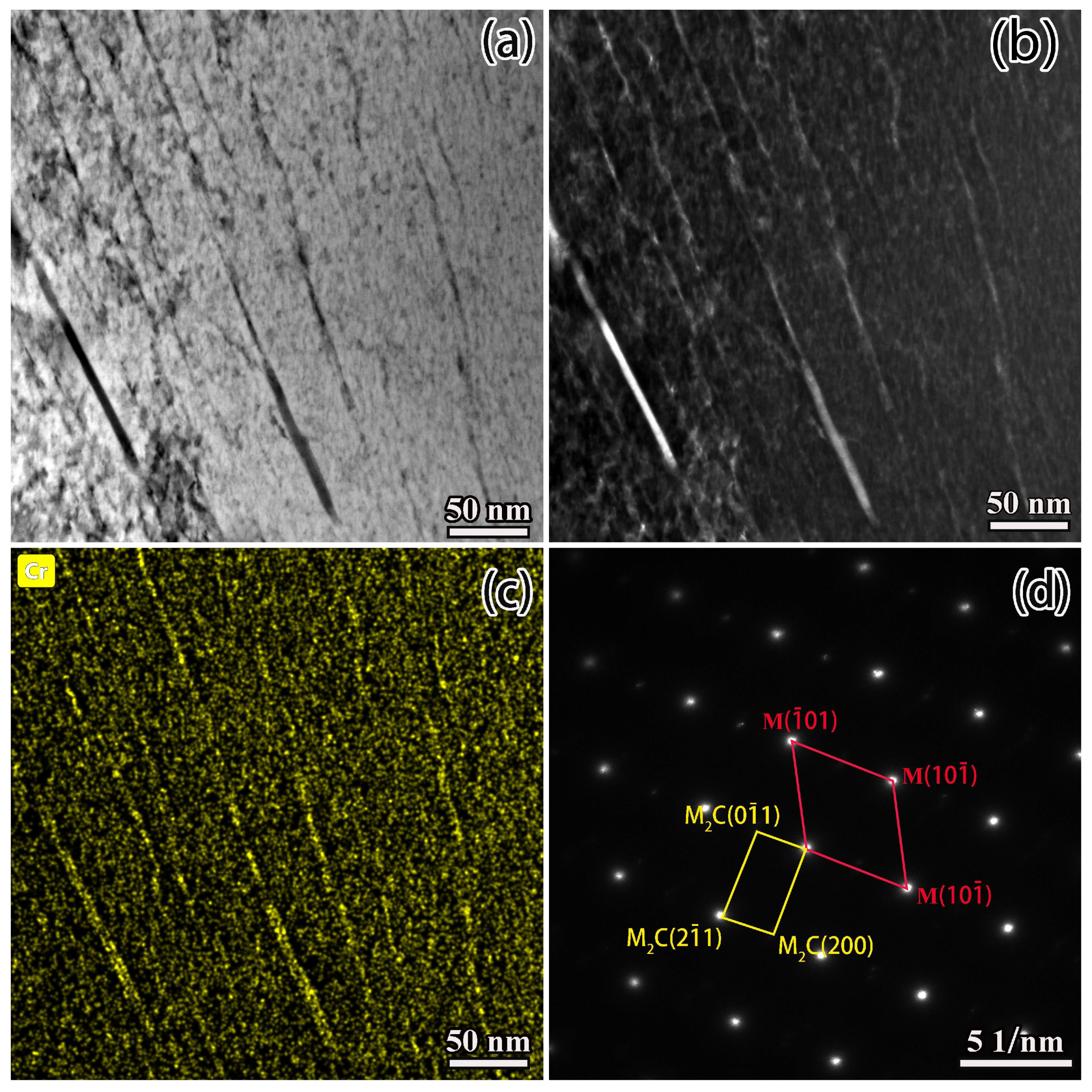
During the conditions of the conventional carburizing process, there was usually a large amount of precipitation of carbide along the grain due to the long boost carburizing time or high carbon potential. This reticulated carbide was eliminated in the final diffusion process with the novel solid-solution carburizing process. However, a large number of carbon atoms improved to diffuse inside the lattice, and the carbon content in the carburized surface layer improved compared with the conventional carburizing process.
(4)
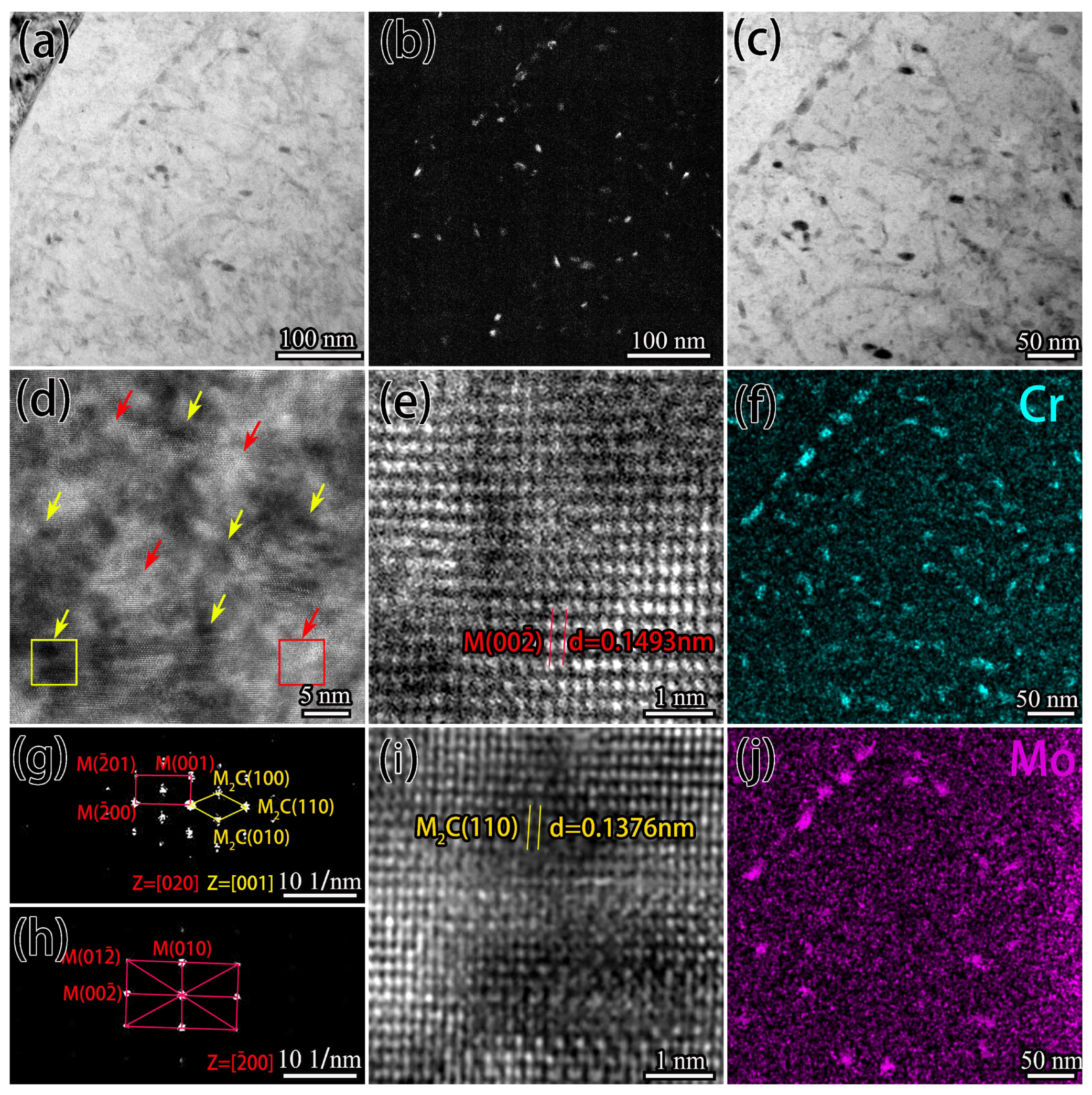
The rise in carburizing temperature could eliminate the reticulated carbides, but grain growth was noticeable, and the strength and toughness match was poor. On the other hand, the novel solid-solution carburizing process could effectively transform micron-carbides along the grain to nano-carbides, achieving full nanosized carbides on the surface with a size of 50–100 nm and good dispersion. Modifying the size, morphology, and distribution of M2C was found to be the main factor in improving the comprehensive mechanical properties such as microhardness and wear resistance.

Author Contributions

Conceptualization, C.W., L.K. and Y.L. (Yong Li); methodology, Y.D. and S.H.; software, Y.D. and Y.L. (Yu Liu); investigation, resources and writing—original draft preparation, Y.D.; writing—review and editing, Y.D., C.W. and S.L. All authors have read and agreed to the published version of the manuscript.

Funding

This research received no external funding.

Institutional Review Board Statement

Not applicable.

Informed Consent Statement

Not applicable.

Data Availability Statement

Data are contained within the article.

Conflicts of Interest

The authors declare no conflict of interest.

References

  1. Teng, B. New Material for Aeroengine—16Cr3NiWMoVNbE Gear Steel. Aeroengine 2003, 2, 34–37. [Google Scholar]
  2. Sebastian, J.; Llc, Q.; Krantz, T.; Center, N.; Shen, T.; Company, T.B. Advanced Gear Alloys for Ultra High Strength Applications. 2011. Available online: https://www.semanticscholar.org/paper/Advanced-Gear-Alloys-for-Ultra-High-Strength-Shen-Krantz/a92917b4ad23e2209e9e8cd04dc32ecb26bc741b (accessed on 1 January 2022).
  3. Morris, J.W., Jr. Making steel strong and cheap. Nat. Mater. 2017, 16, 787–789. [Google Scholar] [CrossRef] [PubMed]
  4. Sebastian, J.; Olson, G.; Snyder, D. QuesTek’s Integrated Computational Materials Engineering (ICME) Approach to the Design and Development of New Materials for Aerospace and Additive Manufacturing Applications. Available online: https://drc.uc.edu/bitstream/handle/2374.UC/745759/ISABE2015_CS%26A_Jason%20Sebastian%20Ph.D._227_MANUSCRIPT_20181.pdf?sequence=2 (accessed on 1 January 2022).
  5. Sebastian, J. New Highly-Processable, High-Strength, High-Durability, Temperature-Resistant Gear Steels. 2011. Available online: https://www.researchgate.net/publication/267900798_New_Highly-Processable_High-Strength_High-Durability_Temperature-Resistant_Gear_Steels (accessed on 1 January 2022).
  6. Wang, Y.; Yang, Z.; Zhang, F.; Wu, D. Microstructures and mechanical properties of surface and center of carburizing 23Cr2Ni2Si1Mo steel subjected to low-temperature austempering. Mater. Sci. Eng. A 2016, 670, 166–177. [Google Scholar] [CrossRef]
  7. Gorockiewicz, R.; Adamek, A.; Korecki, M. Steels for Vacuum Carburizing and Structure of the Carburizing Layer after Low Pressure Carburizing. Ind. Heat. Int. J. Therm. Technol. 2007, 1–16. [Google Scholar]
  8. Gorockiewicz, R. The Benefits of Using 3 Gas Mixture Low Pressure Carburizing (LPC) for High Alloy Steels. 2007. Available online: https://www.researchgate.net/profile/Maciej-Korecki/publication/268376948_The_benefits_of_using_3_Gas_Mixture_Low_Pressure_Carburizing_LPC_for_high_alloy_steels/links/56b08a3b08ae8e37214f8abf/The-benefits-of-using-3-Gas-Mixture-Low-Pressure-Carburizing-LPC-for-high-alloy-steels.pdf (accessed on 1 January 2022).
  9. Heintzberger, P.J. Influence of the Temperature of Vacuum Carburizing on the Thickness of the Carburized Layer and Properties of Steel Parts. Met. Sci. Heat Treat. 2020, 62, 279–284. [Google Scholar] [CrossRef]
  10. Wang, H.; Zhai, Y.; Zhou, L.; Liu, B.; Hao, G. Study on the Process of Vacuum Low Pressure Carburizing and High Pressure Gas Quenching for Carburizing Steels. J. Phys. Conf. Ser. 2020, 1624, 042076. [Google Scholar] [CrossRef]
  11. Kula, P.; Pietrasik, R.; Dybowski, K. Vacuum carburizing—Process optimization. J. Mater. Process. Technol. 2005, 164, 876–881. [Google Scholar] [CrossRef]
  12. Di, C.; Yan, X.; Lv, X.; Yan, C.; Li, D. Effect of Vacuum Carburizing Time on Microstructure and Mechanical Properties of Tantalum Carbide Layer. Met. Mater. Int. 2021, 27, 5008–5016. [Google Scholar] [CrossRef]
  13. Asi, O.; Can, A.C.; Pineault, J.; Belassel, M. The effect of high temperature gas carburizing on bending fatigue strength of SAE 8620 steel. Mater. Des. 2009, 30, 1792–1797. [Google Scholar] [CrossRef]
  14. Tibbetts, G.G. Diffusivity of carbon in iron and steels at high temperatures. J. Appl. Phys. 1980, 51, 4813–4816. [Google Scholar] [CrossRef]
  15. Goldstein, J.I.; Moren, A.E. Moren Diffusion modeling of the carburization process. Metall. Trans. A 1978, 9, 1515–1525. [Google Scholar] [CrossRef]
  16. Ivanov, A.S.; Greben’kov, S.K.; Bogdanova, M.V. Bogdanova Optimization of the Process of Carburizing and Heat Treatment of Low-Carbon Martensitic Steels. Met. Sci. Heat Treat. 2016, 58, 116–119. [Google Scholar] [CrossRef]
  17. Wang, B.; He, Y.; Liu, Y.; Tian, Y.; You, J.; Wang, Z.; Wang, G. Mechanism of the Microstructural Evolution of 18Cr2Ni4WA Steel during Vacuum Low-Pressure Carburizing Heat Treatment and Its Effect on Case Hardness. Materials 2020, 13, 2352. [Google Scholar] [CrossRef]
  18. Trillo, E.A.; Murr, L.E. A TEM investigation of M23C6 carbide precipitation behaviour on varying grain boundary misorientations in 304 stainless steels. J. Mater. Sci. 1998, 33, 1263–1271. [Google Scholar] [CrossRef]
  19. Peng, Y.; Zhang, M.; Xiao, J.; Dong, J.; Du, C. Investigations on carburizing mechanisms of Cr35Ni45Nb subjected to different service conditions in a high-temperature vacuum environment. J. Mater. Res. 2015, 30, 841–851. [Google Scholar] [CrossRef]
  20. Huo, X.; Ning, Y.; LI, L.; Lv, Z.; Chen, S. Research and control of network carbide in GCr15 bearing steel. Mater. Res. Express 2019, 7, 016559. [Google Scholar] [CrossRef]
  21. An, X.; Tian, Y.; Wang, B.; Jia, T.; Wang, Z. Prediction of the formation of carbide network on Grain boundaries in Carburizing of 18CrNiMo7-6 steel alloys. Surf. Coat. Technol. 2021, 421, 127348. [Google Scholar] [CrossRef]
  22. Dou, B.; Zhang, H.; Zhu, J.H.; Xu, B.Q.; Wu, J.L. Uniformly Dispersed Carbide Reinforcements in the Medium-Entropy High-Speed Steel Coatings by Wide-Band Laser Cladding. Acta Metall. Sin. (Engl. Lett.) 2020, 33, 1145–1150. [Google Scholar] [CrossRef]
  23. Zheng, C.; Lv, B.; Zhang, F.; Yang, Z.; Kang, J.; She, L.; Wang, T. A novel microstructure of carbide-free bainitic medium carbon steel observed during rolling contact fatigue. Scr. Mater. 2016, 114, 13–16. [Google Scholar] [CrossRef]
  24. Zheng, C.; Rui, D.; Zhang, F.; Bo, L.; Yan, Z.; Shan, J.; Long, X. Effects of retained austenite and hydrogen on the rolling contact fatigue behaviours of carbide-free bainitic steel. Mater. Sci. Eng. A 2014, 594, 364–371. [Google Scholar] [CrossRef]
  25. Wang, Y.; Zhang, F.; Yang, Z.; Bo, L.; Zheng, C. Rolling Contact Fatigue Performances of Carburized and High-C Nanostructured Bainitic Steels. Materials 2016, 9, 960. [Google Scholar] [CrossRef] [PubMed] [Green Version]
  26. Wang, J.; Zheng, F.; Zhou, J. Effect of the Morphology of Carbides in the Carburizing Case on the Wear Resistance and the Contact Fatigue of Gears. J. Mater. Eng. China 1989, 6, 35–40. [Google Scholar]
  27. Wang, H.; Liu, J.; Tian, Y.; Wang, Z.; An, X. Mathematical Modeling of Carbon Flux Parameters for Low-Pressure Vacuum Carburizing with Medium-High Alloy Steel. Coatings 2020, 10, 1075. [Google Scholar] [CrossRef]
  28. Gregory, N.W. Elements of X-Ray Diffraction. Contemp. Phys. 1957, 20, 87–88. [Google Scholar] [CrossRef]
  29. Ishida, K. Calculation of the effect of alloying elements on the M s temperature in steels. J. Alloys Compd. 1995, 220, 126–131. [Google Scholar] [CrossRef]
  30. Su, S.; Wang, L.; Chen, C.; Wang, Y.; Li, J. Gradient microstructure evolution and hardening mechanism of carburized steel under novel heat treatment. Mater. Lett. 2020, 280, 128486. [Google Scholar] [CrossRef]
  31. Zhang, Y.; Zhan, D.; Qi, X.; Jiang, Z. Effect of tempering temperature on the microstructure and properties of ultrahigh-strength stainless steel. J. Mater. Sci. Technol. 2019, 35, 1240–1249. [Google Scholar] [CrossRef]
Figure 1. Schematic diagram of carburizing process: (a) conventional carburizing process; (b) novel solid-solution carburizing process.
Metals 12 00379 g001
Figure 2. The mini-tensile specimens were fabricated out of the heat-treated C-rings’ core: (a) vertical sampling position; (b) specimen thickness and sampling distance from carburizing surface depth.
Metals 12 00379 g002
Figure 3. Microstructure of process L2: (a) carburizing layer; (bd) OM images of the morphology of the carburized layer at 0.1, 1.0, and 1.5 mm, respectively; (eg) SEM images of the morphology of the carburized layer at 0.1, 1.0, and 1.5 mm, respectively.
Metals 12 00379 g003
Figure 4. Comparison of different carburizing processes at 1000 °C: (a) carbon concentration profile; (b) microhardness profile; (c) the depth of effective carburizing layer.
Metals 12 00379 g004
Figure 5. SEM of surface layer 0.1 mm: (a) process L1; (b) process L2; (c) process L3.
Metals 12 00379 g005
Figure 6. EMPA at 0.1 mm on the surface of process L2.
Metals 12 00379 g006
Figure 7. M7C3 carbide statistics under different carburizing processes: (a) volume percent of carbide; (b) carbide size distribution.
Metals 12 00379 g007
Figure 8. XRD pattern at 0.1 mm of the carburized surface layer.
Metals 12 00379 g008
Figure 9. Thermo-Calc phase diagram of C61 steel.
Metals 12 00379 g009
Figure 10. Under different carburizing temperature conditions: (a) carbon concentration profile; (b) microhardness profile.
Metals 12 00379 g010
Figure 11. Carbides at 0.1 mm in the surface layer under L2 process: (a,b) M7C3-type carbide; (c) calibration of (b,d) bright-field image of M2C; (e) dark-field image of M2C; (f) calibration of M2C.
Metals 12 00379 g011
Figure 12. Carbides at 0.1 mm in the surface layer under L4 process: (a,b) bright- and dark-field image of carbides; (c,f,j) carbide-enriched areas and corresponding Cr and Mo elemental mapping analysis; (d) HRTEM of carbide-enriched areas; (e,i) HRTEM for the red and yellow regions of (d); (g) the FFT corresponding to figure; (e,h) the FFT corresponding to figure (i).
Metals 12 00379 g012
Figure 13. Fitted image of grain size: (a) process L2; (b) process L4; (c) process N.
Metals 12 00379 g013
Figure 14. Simulation of new solid-solution carburization: (a) in the presence of network carbide conditions; (b) the dissolution process of network carbides; (c) rapid diffusion of carbon atoms along grain boundaries.
Metals 12 00379 g014
Figure 15. Comprehensive performance of the novel solid-solution carburizing process: (a) carbon content; (b) microhardness; (c) mechanical properties.
Metals 12 00379 g015aMetals 12 00379 g015b
Figure 16. Carbides in 0.1 mm depth of carburizing layer for novel solid-solution carburizing process: (a,b) bright- and dark-field image of carbides; (c) Cr elemental mapping analysis; (d) calibration of (a).
Metals 12 00379 g016
Table 1. Elemental content (mass fraction) of the C61 steel.
ElementCCrNiCoMoVFe
Content0.153.59.5181.10.08bal
Table 2. Carburizing process.
ProcessCarburizing (Divided into Three-Stage)QuenchingSub-Zero CoolingTempering
TemperatureBoosting (C = 1.3%)Diffusing (C = 0.9%)
L11000 °C 30 min210 minOQ−196 °C × 1 h482 °C × 16 h
L21000 °C60 min180 min
L31000 °C 60 min420 min
L41100 °C 60 min180 min
N1050 °C 60 min180 min
1100 °C
Table 3. Comparison of microstructure and property parameters of the different carburizing processes.
ProcessCarbon ContentMs PointMartensite AusteniteM7C3 CarbideSurface Hardness
L10.75%245.05 °C 93.98%4.65%1.37%740 HV
L20.54%314.35 °C90.69%4.58%4.73%725 HV
L30.52%320.95 °C98.23%4.31%1.71%720 HV
L40.88%202.15 °C98.92%1.08%-854 HV
Publisher’s Note: MDPI stays neutral with regard to jurisdictional claims in published maps and institutional affiliations.

