Article

Effect of Shortened Post Weld Heat Treatment on the Laser Welded AA7075 Alloy

1
Institute for Production Engineering and Forming Machines—PtU, The Technical University (TU) of Darmstadt, Otto-Berndt-Str. 2, 64287 Darmstadt, Germany
2
Department for Cutting and Joining Manufacturing Processes, The University of Kassel, Kurt-Wolters-Str. 3, 34125 Kassel, Germany
*
Author to whom correspondence should be addressed.
Metals 2022, 12(3), 393; https://doi.org/10.3390/met12030393
Submission received: 18 January 2022 / Revised: 10 February 2022 / Accepted: 22 February 2022 / Published: 24 February 2022

Abstract

:
The present study provides an overview of previous studies on the welding of the AA7075-T6 aluminum alloy, followed by an investigation of the influence of short-time solution annealing on the mechanical properties of the weld. Conventional laser welding of Al-Zn-alloys leads to a low weld strength, which makes a post weld heat treatment (PWHT) favorable. The PWHT includes solution annealing, quenching and subsequent aging. For solution annealing, different holding times and cooling rates are investigated in this study. The focus of the investigation is on a short solution annealing time, which on the one hand is ecological and economically favorable and on the other hand offers great potential for inline heat treatments. The shortest solution annealing time of 10 s shows a significant increase in weld strength (joint efficiency of 72%), compared to the non-heat treated weld (joint efficiency of 52%). The microstructural analysis reveals that the cooling rate after solution heat treatment affects the formation of precipitates in the microstructure of the welded AA7075 alloy. Moreover, the enhancement of mechanical properties is related to the formation of Mg-Al-Cu and Mg-Zn rich precipitates.

1. Introduction

Lightweight structures are of great interest in industry. A recent example is the need for high strength lightweight bicycle frames for e-bikes to reduce overall weight and increase the payload. Another aspect is more than ever the careful use of resources and the reduction of CO2 by the reduction of material usage and saving energy in the use phase of transport devices. One way to reduce the weight of structures is the use of high strength lightweight materials, such as the AA7075 aluminum alloy. A major problem is the poor weldability of Al-Zn-alloys, such as the AA7075 alloy in general [1]. Most data sheets mention AA7075 as a “non-weldable” alloy. Particularly in the aerospace industry, where the AA7075 alloy is widely used, joining technologies like riveting and bolding are used with all their disadvantages. For that reason, many attempts have been made in the past to weld the alloy using various processes, as illustrated in the following section.
Laser welding offers many advantages such as high processing speed, high energy density, non-contact energy input, high quality and a high degree of automation due to high flexibility [1]. For this reason, laser welding is now widely used in industry [2]. Laser welding of high strength aluminum alloys with a high Zn content is not widely used in industry due to insufficient properties of the welding seam [2]. The poor weldability is a result of keyhole-induced porosity, temperature dependent hydrogen solubility, and hot cracking tendency [3]. The different vapor pressures of the individual alloying elements lead to instabilities of the vapor capillary and thus to keyhole-induced porosity [4]. In the following section, the previous investigations on the welding of the high strength Al-Zn-aluminum alloy AA7075 are described in terms of the joint efficiency (Z) achieved. Joint efficiency is defined by the ratio of the ultimate tensile strength (UTS) of the welding seam to the UTS of the base material for laser welded joints [5,6]:
Z = R m ,   Welding   seam R m ,   Base   material .
Liu and Northwood [7] investigated two different welding processes for welding a high strength AA7075-T6 aluminum sheet with a thickness of 9.5 mm. It is interesting to note that the specimens were aged at 120 °C for 26 h after welding, without prior solution annealing and quenching. For the tungsten arc (GTA) welding process, the joint efficiency is 71% without and 74% with subsequent heat treatment. For the CO2 laser beam welding process, the joint efficiency is 83% without heat treatment and 91% with heat treatment. It was found that fracture occurs in the fusion zone rather than the heat-affected zone as magnesium and zinc vaporize, leading to a reduction in precipitation strengthening in this region. Holzer et al. [8] compared a single-beam laser welding process to a dual-beam laser welding process (wave disc laser) on 2 mm thick AA7075-T6 sheets at different welding speeds. They recommend the lower welding speed in order to obtain high strength values, as a higher welding velocity leads to the formation of hot cracks in the structure. They performed a heat treatment, consisting of a sequence of solution annealing (30 min at 480 °C), water quenching and artificial aging (24 h at 125 °C), to reduce the softening effect in the weld seam and heat-affected zone. Single beam laser welding results in a UTS of the welding seam of 375 MPa without heat treatment and 520 MPa with heat treatment. By using dual laser beam welding, the UTS is increased to 400 MPa without heat treatment and 540 MPa with heat treatment. No information is given on the strength of the base material. As a result of this investigation, higher process stability and also higher joint efficiency were obtained.
Laser beam welding processes using an ytterbium fiber laser and a Nd:YAG laser were investigated in detail by Enz [9], and [6] Enz et al. [9] present a process in which the AA7075 aluminum alloy is welded with a filler wire (AA5087) and a vanadium foil. Increasing keyhole stability is one of the keys to achieve a good welding seam when welding Al-Zn-alloys, such as the AA7075 alloy [6]. The approach to improve the keyhole stability and thus the welding seam is to defocus the laser beam. Defocusing results in lower keyhole pressure and thus improved degassing behavior and lower porosity in the weld. Enz et al. achieved a joint efficiency of 69% when welding AA7075-T6 sheets with a thickness of 2 mm without subsequent heat treatment [6].
Due to the poor weldability of the AA7075 alloy and the need for special laser welding techniques to weld the alloy to high quality, several welding processes have been investigated in the past. In particular, many tests have been carried out for friction stir welding (FSW). Rajakumar et al. [5] achieved a joint efficiency of 77% in a friction stir welding process without subsequent heat treatment. The UTS of the base material of 485 MPa is low compared to the common BLS of the AA7075 alloy of 550–610 MPa. Bayazid et al. [10] performed a special heat treatment procedure after friction stir welding. The heat treatment is characterized by a cyclic solution heat treatment (CST) of three heating and cooling cycles between the temperature of 400 °C and 480 °C with subsequent water quenching and aging (24 h at 130 °C). They showed that the FSW process deteriorated the mechanical properties, while the CST improved the mechanical properties by retaining the fine grain structure and propagating fine, stable MgAlCu precipitates. The joint efficiency of the FSW process without heat treatment is 82% and with heat treatment 109%, which means that the weld is even stronger than the base material.
Sajadifar et al. [11] investigated the effect of a post weld heat treatment (PWHT) on the friction stir welded AA7075 alloy. The PWHT was conducted with different quenching media (air and water) after solution annealing for 30 min. After solution annealing, the aging process is conducted at 120 °C for 20 h. The authors claimed that slower cooling rates after PWHT lead to the separation of large precipitates along the grain boundaries, resulting in the formation of a precipitate-free zone (PFZ). The mechanical properties of AA7075 alloy reduce due to the PFZs in the specimens, which cool less after solution heat treatment. Therefore, the higher cooling rate, that is, water quenching, is recommended to enhance the mechanical properties of welded AA7075 alloys. Moreover, the joint efficiency without heat treatment is 85%, with water quenching 95% and with air quenching only 38%. Another approach is a GTA welding process for AA7075 sheets with a TiC nanoparticles containing filler rod by Sokoluk et al. [12]. The TiC nanoparticles enhance crack-free fusion zone formation by altering grain morphologies during gas tungsten arc welding of AA7075 alloy. The achievable joint efficiency is 64% without heat treatment and 90% with a solution annealing process (1 h at 480 °C) and subsequent aging process (19 h at 120 °C). In summary, subsequent heat treatment after the welding process recovers the mechanical properties, that is, strength, of the weld by homogenizing the microstructure.
In the current literature, there are only a limited number of studies on the short solution annealing time for PWHT. Therefore, it is of great interest for inline heat treatment within seconds. One application for short-time solution annealing is roll forming and welding of a high strength AA7075 tube with subsequent induction heating and quenching, as illustrated in Figure 1. Roll forming is suitable for integrating further processes, such as welding, punching or milling into the process chain. Some investigations in the past also focused on in-line heat treatment to achieve tailored properties [13] or on heat treatment of the welding seam [14]. Solution annealing time is variable within the process and depends on the process speed but is still limited due to the endless length of the induction coil or continuous furnace. Fast heating is possible by inductive heating of the tube. Tailored mechanical properties of the tube can be achieved by targeted quenching of the tube. Targeted quenching of the welding seam is also possible within the process chain.
One of the main objectives of the present study is to understand the effect of PWHT on the mechanical properties of the weld zone. In this context, laser welded AA7075 alloys were heat treated in various quenching media, that is, water, oil, air, with different cooling rates. In addition, the mechanical properties of the various heat treated welded samples were characterized by tensile tests and hardness measurements. The fracture surface of standard (non-PWHT), water and air quenched samples was also investigated. In addition, the presence of precipitates in the weld seam was investigated by microstructural analysis.

2. Experimental Setup

2.1. Material and Welding Experiments

In the experiments, a butt joint welding process of two AA7075 sheets with a thickness of 1.5 mm was conducted. The tensile strength of the BM in T6-condition is 590 MPa and the Vickers hardness is 202 HV. Table 1 illustrates the chemical composition of the “as-received” AA7075-T6 alloy. The main alloying elements are zinc, magnesium and copper.
The laser welding tests were carried out using an ytterbium fiber laser (IPG YLS-3000-S2T, IPG Laser GmbH, Burbach, Germany) and fixed focal length optics of type MWO44 (Reis Lasertec, Würselen, Germany), which has an imaging ratio of 2:1. Due to the imaging ratio, the experiments resulted in a focus diameter of 400 µm when using a 200 µm fiber optic cable. The standard parameters of the welding process were obtained from the pretests with variation of the welding speed (Table 2). In preliminary studies, the defocusation of +14 mm showed the best welding results due to the highest keyhole stability. Compared to other measures for increasing the quality of the welding seam, defocusing is easy to apply in existing laser welding processes. The defocusing leads to a larger laser spot diameter. This requires a laser power of 3 kW for the experiments. To avoid critical deflection of the laser beam, the welding angle is set to 6°. The shielding gas cover with argon is located on the top of the welding seam.
The length of the welding seam is 300 mm and the specimens are prepared by milling to achieve a zero gap for the welding process. Immediately before welding, the specimens are cleaned with acetone. Figure 2 illustrates the experimental setup for laser welding. The orientation of the tensile specimen is 90° to the rolling direction of the BM. Methods for evaluating the welds include a uniaxial tensile test with a Zwick Roell 100 kN material-testing machine (ZwickRoell GmbH & Co. KG, Ulm, Germany) with optical strain measurement. Vickers Hardness is measured with a KB30S-FA hardness tester (KB Prueftechnik GmbH, Hochdorf-Assenheim, Germany). A Leica Z16 APO and a Leica DM2700 (Leica Microsystems GmbH, Wetzlar, Germany) are used for microscopic examinations.
The morphology and chemical composition of the precipitates in the welded AA7075 alloy samples were studied by SEM (Zeiss REM Ultra Plus Gemini, Carl Zeiss Microscopy Deutschland GmbH, Oberkochen, Germany), EBSD analysis (Bruker e-Flash, Bruker Corporation, Billerica, USA) and EDS analysis (Bruker XFlash 6|60, Bruker Corporation, Billerica, MA, USA). In addition, the fracture surfaces of standard, water-quenched and air-quenched samples were investigated by SEM analysis using a JEOL JSM 6610LV SEM (JEOL Ltd., Akishima, Japan). Moreover, grain size analysis was conducted by the line intercept method using the ImageJ image processing program [15].

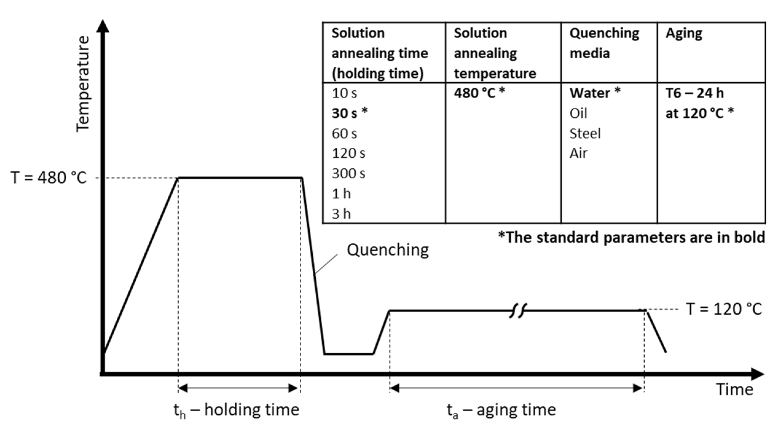
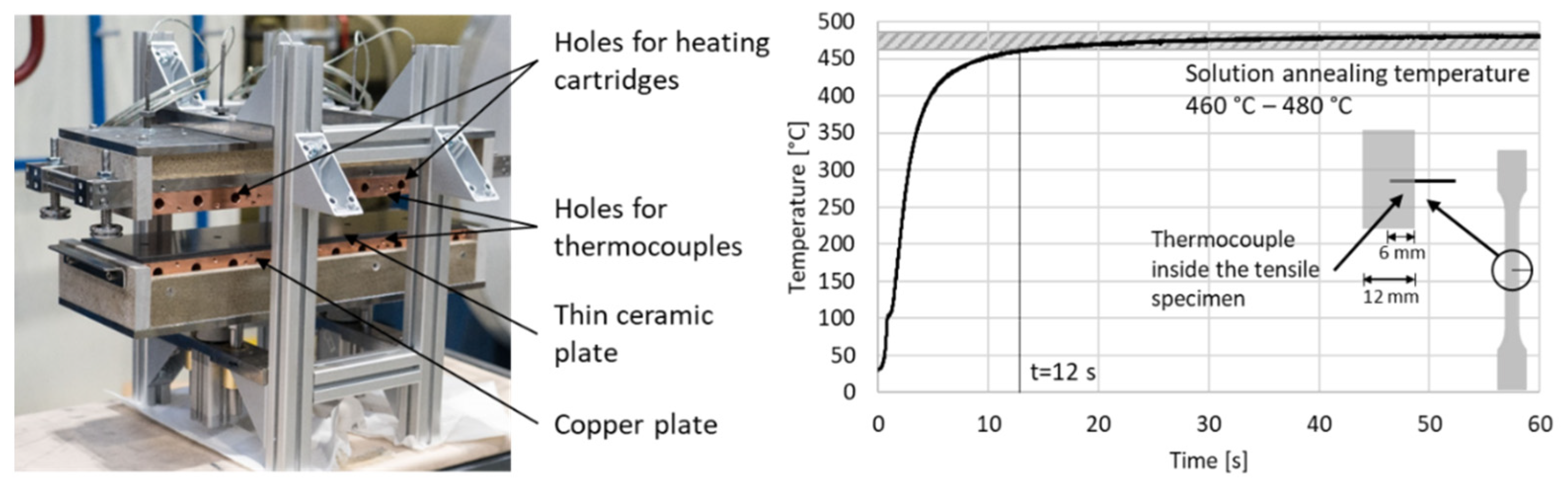
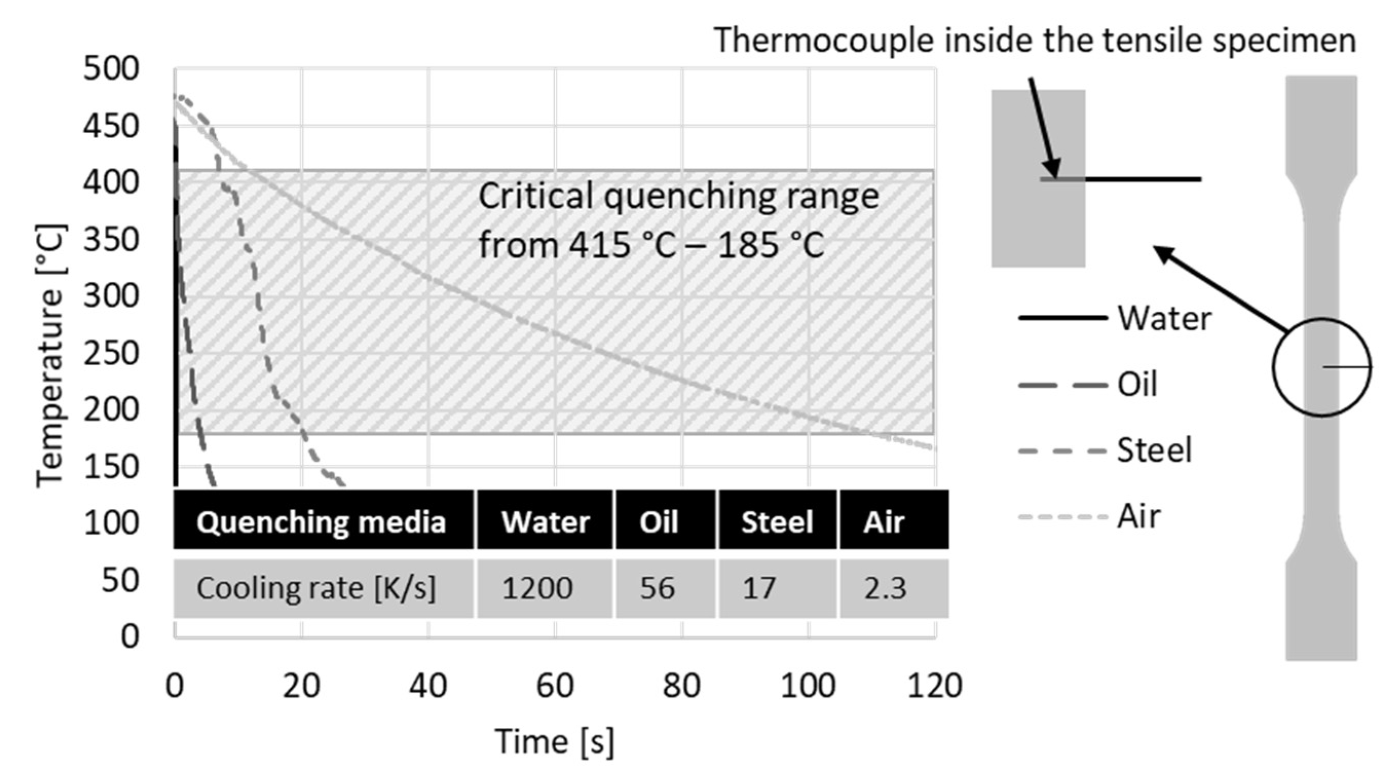
2.2. Post Weld Heat Treatment

In this publication, the influence on different PWHT on the mechanical and metallurgical properties of the weld is investigated in the frame of inline heat treatment. To understand the influence of the PWHT on the welding seam, a heat treatment with different annealing times and various cooling rates for the quenching was performed after the welding process. In accordance with inline heat treatment, the focus is on short solution annealing times and a high heating rate. Figure 3 shows the parameters for PWHT, with the standard parameters in bold. After laser welding, the tensile specimens, used for heat treatment, were cut from the sheet with a width of 12 mm and a thickness of 1.5 mm. The geometry of the tensile specimen, which is also shown in Figure 2, is according to DIN EN ISO 4136 [16].
Figure 4 illustrates the heating device and a heating curve for the short-time solution annealing process. The solution annealing process was performed in a contact-heating device and aging in a Binder FDL 115 convection furnace (BINDER GmbH, Tuttlingen, Germany). During the solution annealing process, the temperature was measured by a thermocouple (type K), placed in a 6 mm deep hole inside the tensile specimen. The heat transfer to the tensile specimen is conductive, so the heating device heats the specimen to solution annealing temperature faster than a convection furnace with a heating rate of approx. 1.7 K/s [17]. The fast heating rate of approx. 36 K/s in the temperature range from 20 °C to 460 °C makes the process comparable to the process conditions of an inline heat treatment by induction heating. According to Zou et al. and [18], the solution annealing temperature of the AA7075 alloy is in the range of 460 °C–480 °C. After 12 s, the specimen is heated to 460 °C. The contact (copper) plates of the heating device have a temperature of 480 °C. According to the definition, the solution annealing time starts from the moment the sample has reached the temperature of 460 °C.

3. Results and Discussion

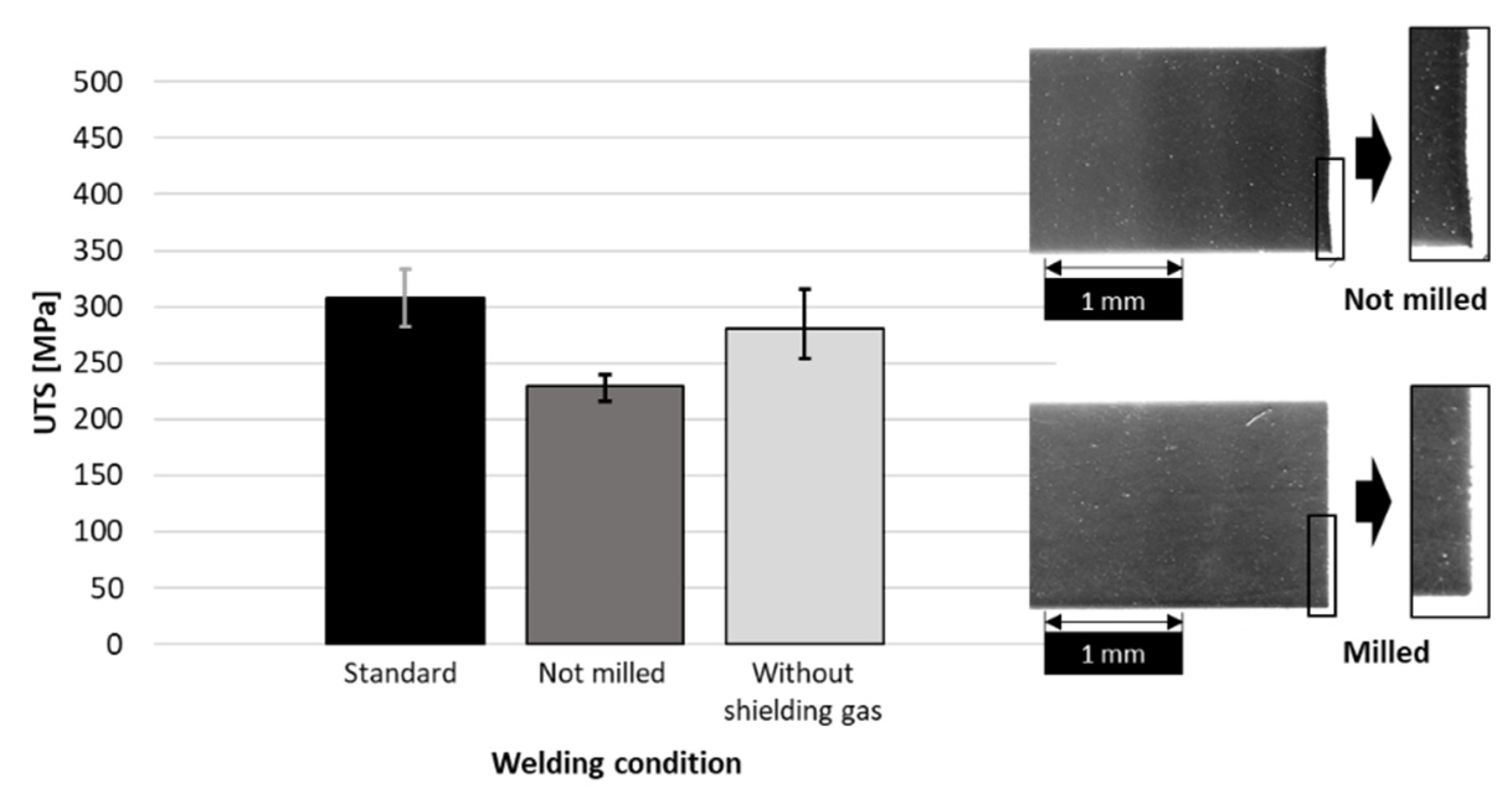
3.1. Influence of the Welding Parameters

The first series of tests focused on the influence of the seam edge preparation and the shielding gas. Before welding, the plates were prepared in three conditions. The standard specimen was milled before welding and was welded with shielding gas. If the specimen is not milled before welding, the seam edge of the plate is not perfectly vertical to the top of the sheet and the welding gap is undefined. Oxide inclusions reduce the mechanical strength of the welding seam. The use of shielding gas prevents the penetration of the weld with oxide or hydrogen. Both lead to defects, such as hydrogen induced porosity or oxide inclusions in the welding seam. Figure 5 shows the influence of specimen preparation and shielding gas on the UTS of the welding seam. Error bars for the tensile tests refer to the minimum and maximum values of the UTS.
The second parameter investigated in the experiments was the welding speed. Excessive heat input at a low welding speed leads to an undercut and to an enlargement of the heat-affected zone (HAZ) and thus to an increasing risk of a keyhole collapse. Although higher welding speed reduce the possibility of an undercut, the lower material cohesion, as well as incomplete weld penetration, lead to a reduction in joint efficiency.
Figure 6 shows the influence of welding speed on the UTS of the welding seam. The laser power was 3 kW for all experiments. The highest joint efficiency of 52% (308 MPa) was achieved at a welding speed of 1.76 m/min, which applies to all further investigations. This results in an energy input of 1020 J/cm.
Figure 7 shows a characteristic welding seam for the standard welding condition. The weld metal (WM), fusion zone (FZ), heat-affected zone (HAZ) and the base material (BM) can be identified. An undercut of the welding seam can be detected. The presence of small pores could arise from hydrogen penetration due to the missing shielding gas cover on the bottom side. Nevertheless, the weld is suitable for subsequent investigations regarding the presence of pores, also according to DIN EN ISO 13919-2 [19]. Furthermore, the metallurgical phases relevant to the investigation of the influence of PWHT on the welding seam are not affected by the pores.

3.2. Influence of the Post Weld Heat Treatment

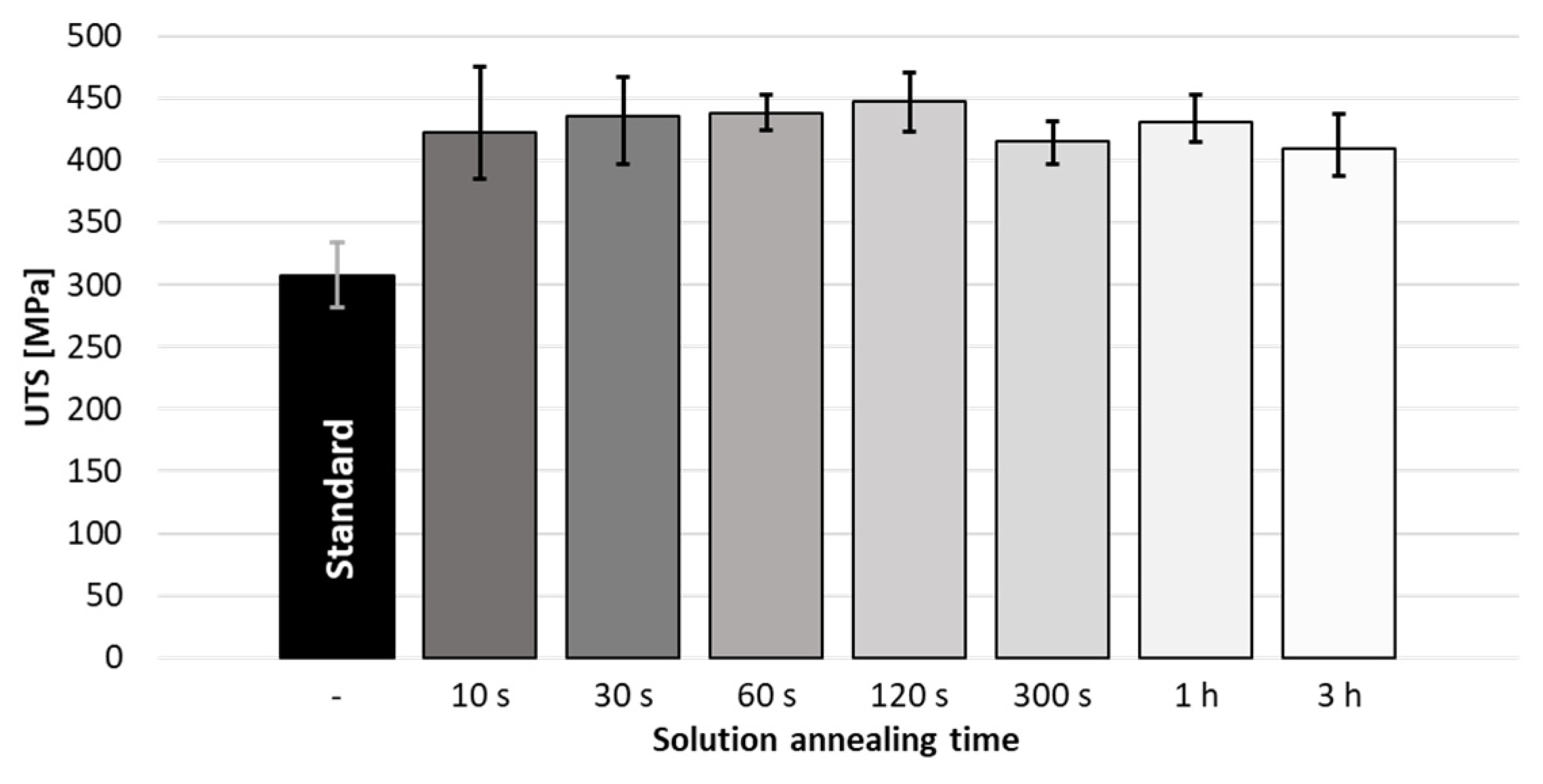
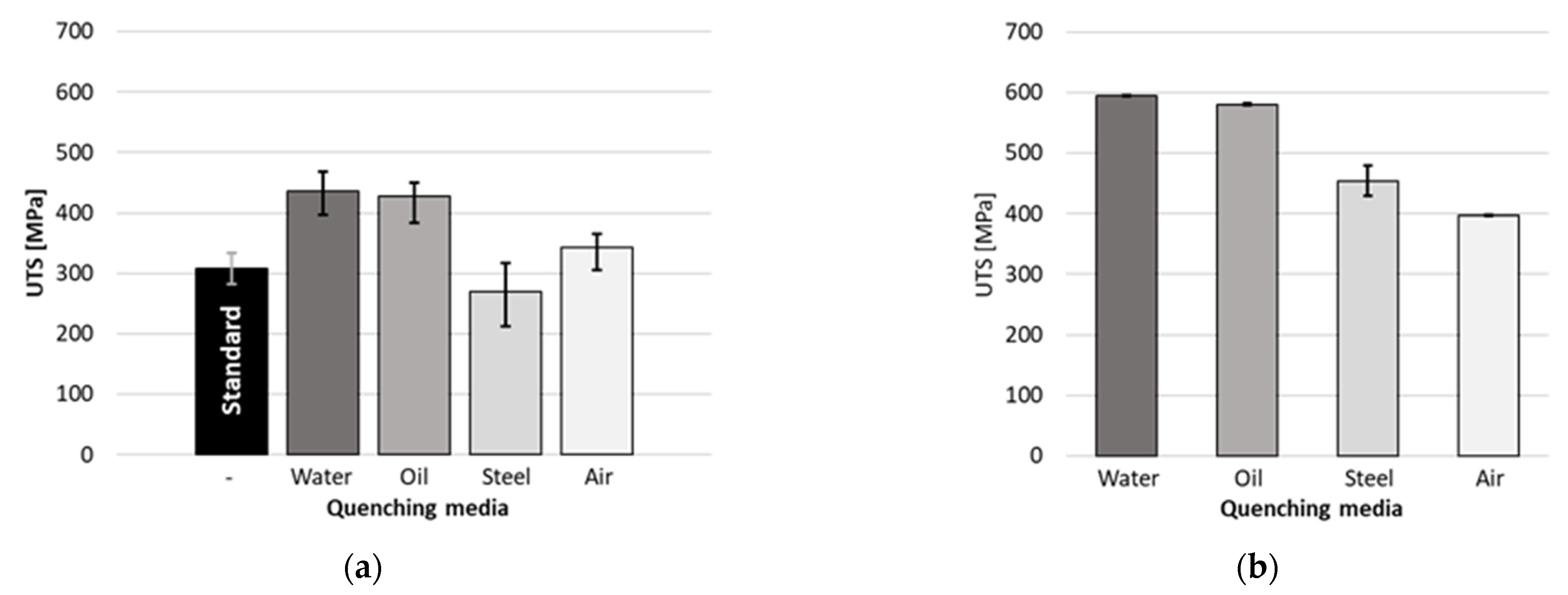
3.2.1. Mechanical Properties from Tensile Tests

In the following section, the influence of the solution annealing time on the welding seam is investigated. Theoretically, a sufficiently long solution annealing time leads to the complete dissolution of the alloying elements in the aluminum [20]. According to DIN 29850 [21], the time required to dissolve the alloying elements is strongly dependent on the initial state of the alloy. For the T6-condition, a short-time solution annealing is sufficient to achieve good mechanical properties after fast quenching and an aging process of 24 h at 120 °C. Nevertheless, the solution annealing time should not be less than five minutes. For the soft annealed O-condition or the F-condition (as fabricated), longer solution annealing times are required to achieve high strength after artificial aging. According to DIN 29850, the solution annealing time for a sheet with a thickness of 1.5 mm is 6 min for the T6- and 10 min for the O- or F-condition in a salt bath.
On the other hand, the short annealing times, that is, 10, 30, 60 and 120 s, are preferred in this study because there are no detailed studies on the WM and the FZ in the welded specimen in terms of structure and distribution of precipitations [22], which means that there is no recommended solution annealing time according to a standard. Figure 8 shows the influence of solution annealing time on the mechanical properties. The results show a significant positive effect of heat treatment in general, but only a small dependence of the mechanical properties of the welding seam on the solution annealing time. There is no advantage to annealing the samples longer than 120 s, when the maximum UTS of 448 MPa (joint efficiency of 76%) is achieved. The shorter solution annealing times lead to a remarkable increase in the UTS compared to the standard non-heat treated specimen, Figure 8. At a solution annealing time of 30 s, the UTS is 435 MPa, which corresponds to a joint efficiency of 74% and even at a 10 s solution annealing time, the joint efficiency is still 72%.
After the solution annealing time, the influence of the cooling rate on the welding seam was investigated. According to Liu et al. [23], the cooling rate in the temperature range of 415 °C to 185 °C should be at least 300 K/s to avoid unintended precipitations during the quenching process of Al-Mg-Zn-Cu alloys. Figure 9 shows cooling curves for different quenching media and cooling rates for the various quenching processes at the critical quenching temperature of 415 °C to 185 °C. The temperature of tensile test samples was measured by thermocouples (type K), placed inside the tensile specimens. Apparently, water quenching has the highest cooling rate, followed by oil and steel quenching, while air quenching has the lowest cooling rate. During steel quenching, the specimen was placed on a steel plate at a temperature of 25 °C.
The investigations aim to show whether high cooling rates have a positive effect on the mechanical properties of the welding seam. Figure 10a illustrates the influence of the quenching speed during the PWHT on the properties of the welding seam. The oil-quenched specimen has a joint efficiency of 73% (428 MPa). The quenching speed of 17 K/s, reached after steel quenching is not beneficial for the material properties, as the UTS (270 MPa) of the welding seam is lower than the untreated “standard” welded sample. On the other hand, the UTS increases to 343 MPa when the quenching speed is reduced by air quenching.
The behavior of the overall mechanical properties of the welds reflects the behavior of the BM. Water-quenched tensile specimens have a UTS of 595 MPa, while the oil-quenched specimens have a UTS of 581 MPa, Figure 10b. The values for the BM were obtained from samples solution annealed in a Nabertherm N41/H furnace at 480 °C for 300 s and aged at 120 °C for 24 h.
After comparing the UTS values of PWHT samples in various conditions, the stress-strain diagram of standard, water and air-quenched specimens are compared in Figure 11. The water-quenched sample has the highest mechanical strength compared to the other samples. The air-quenched specimen, on the other hand, shows plastic elongation above 3%. For subsequent processes, such as rotatory swaging or tube drawing, the formability of the material is required. After quasi-static tensile tests, the fracture of the standard specimens occurs in the weakest welded zone (Figure 12a). The same behavior is also observed in the welded zone of air-quenched and water-quenched samples after subsequent heat treatment (Figure 12b,c), which means that PWHT has no significant effect on the fracture location.

3.2.2. Hardness Measurement

For the evaluation of the influence of PWHT on the welding seam, hardness tests are performed to measure Vickers hardness HV 0.3 perpendicular to the welding direction. The PWHT has an influence on the BM, the HAZ, the FZ and the WM of the material. The hardness distribution of the welding seams of AA7075 alloy is illustrated in dependence on solution annealing time, quenching media in the Figure 13 and Figure 14. The hardness in the BM of non-heat treated standard specimens is measured as 202 HV. In the welding seam, a significant decrease in the hardness values of the HAZ, 170 HV, towards the region of the WM, 103 HV, can be observed (Figure 13). As can be seen, the WM zone is the weakest zone in terms of hardness and that could be the reason for the fracture of the standard sample in this area.
Moreover, subsequent heat treatment with different annealing times enhanced the hardness values. Almost all water-quenched specimens exhibited a similar hardness profile throughout the welding seam. The 10 s solution-annealed specimen has the lowest hardness values of about 185 HV. On the other hand, longer solution annealing times lead to higher hardness values, corresponding to the tensile test results in Figure 8. With a solution annealing time of 30 s, the hardness increases slightly to values of about 220 HV. A further increase of the solution annealing time does not lead to significant changes of the hardness curves. In summary, it can be said that with higher solution annealing times, the influence of time becomes smaller.
Figure 14 reveals the influence of the cooling rate on the hardness profile. The hardness of the oil-quenched specimen, similar to that of the water-quenched specimen, varies across the cross-section of the weld. The minimum hardness level in the middle of the WM of the oil-quenched specimen, about 185 HV, is lower than that of the water-quenched sample, 200 HV. The reason for this could be related to the microstructure, which will be discussed in the following section. Although the maximum hardness of 190 HV is about 1 mm from the center of the WM, a sharp decrease of 100 HV, is observed in the middle of the WM of the steel-quenched specimen. When approaching the HAZ, the hardness drops to a level of 160 HV. The hardness drop agrees well with the tensile test results, as the steel-quenched specimen has the lowest UTS according to the tensile test results (Figure 10). The hardness curve of the air-quenched specimen is inverse to that of the non-heat treated specimen, with the lowest hardness observed around 120 HV. Due to the relatively slow cooling rate, it is assumed that a coarse grain structure could be formed in the HAZ, resulting in a reduction of the hardness. On the contrary, the hardness of the WM is similar to that of the other heat treated specimens.

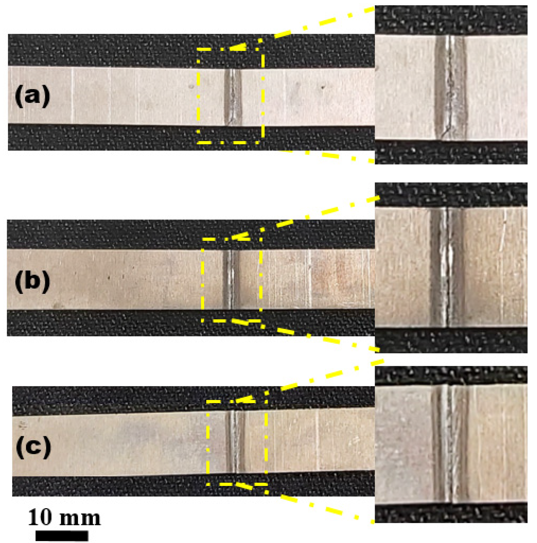
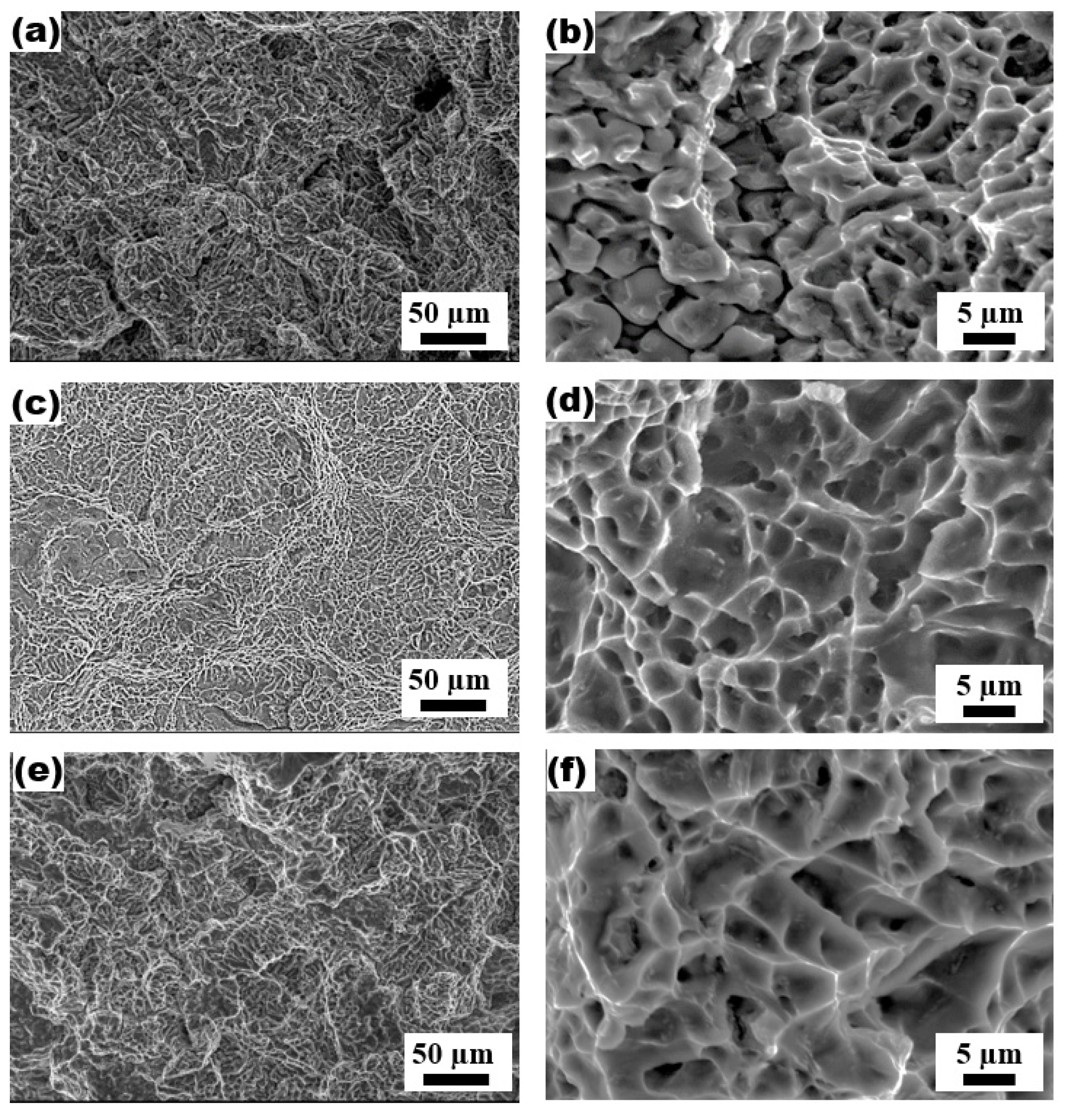
3.2.3. Fracture Surface Analysis

The fracture surfaces are observed after the tensile test to compare the effects of various conditions on the ductility of laser-welded joints. Figure 15 shows the fractured surfaces of the standard (no heat treatment), air-quenched, and water-quenched specimen. SEM images reveal that the fracture surfaces are covered with dimples, indicating that the dominant fracture mechanism for welded-specimen is microvoid coalescence [24,25,26]. The microvoids start to initiate at the interface of the matrix. With increasing load, the growing and changing of the voids leads to coalescence of the voids and subsequently to the final fracture.
The fracture surface of the standard welded sample after the tensile test exhibits less obvious features of ductile fracture compared to the other two conditions. The fracture mode is observed as a combination of transgranular and intergranular fractures, with intergranular failure dominating, Figure 15a,b. Moreover, these results are consistent with the observed brittle mechanical behavior in the stress-strain diagram in Figure 11. Zhang et al. also found the predominant intergranular fracture at the FZ of the aluminum alloy after the tensile test. In contrast, the fracture surfaces of air-quenched and water-quenched PWHT-samples consist of regions that display relatively larger and homogenously distributed dimples (Figure 15c–f). The dimples in the surface of the water-quenched samples (Figure 15c,d) are rather smaller than those of the air-quenched samples, which reveals that the ductility of the water-quenched samples is slightly worse. On the other hand, the presence of many fine dimples on the fracture surface shows the higher ductility of the air-quenched specimen (Figure 15e,f). The fracture analysis is also consistent with the observed ductile behavior during the quasi-static tensile test (Figure 11), indicating that the air-quenched laser-welded Al-alloys exhibit the best ductility test in comparison with the water-quenched laser-welded specimen.

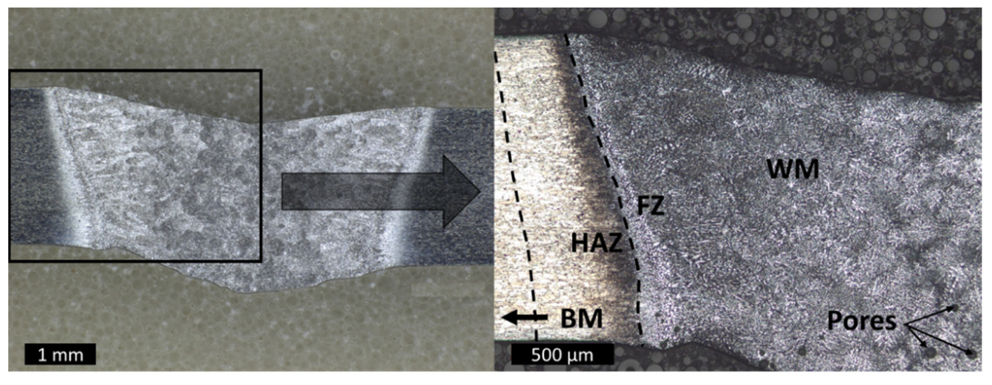
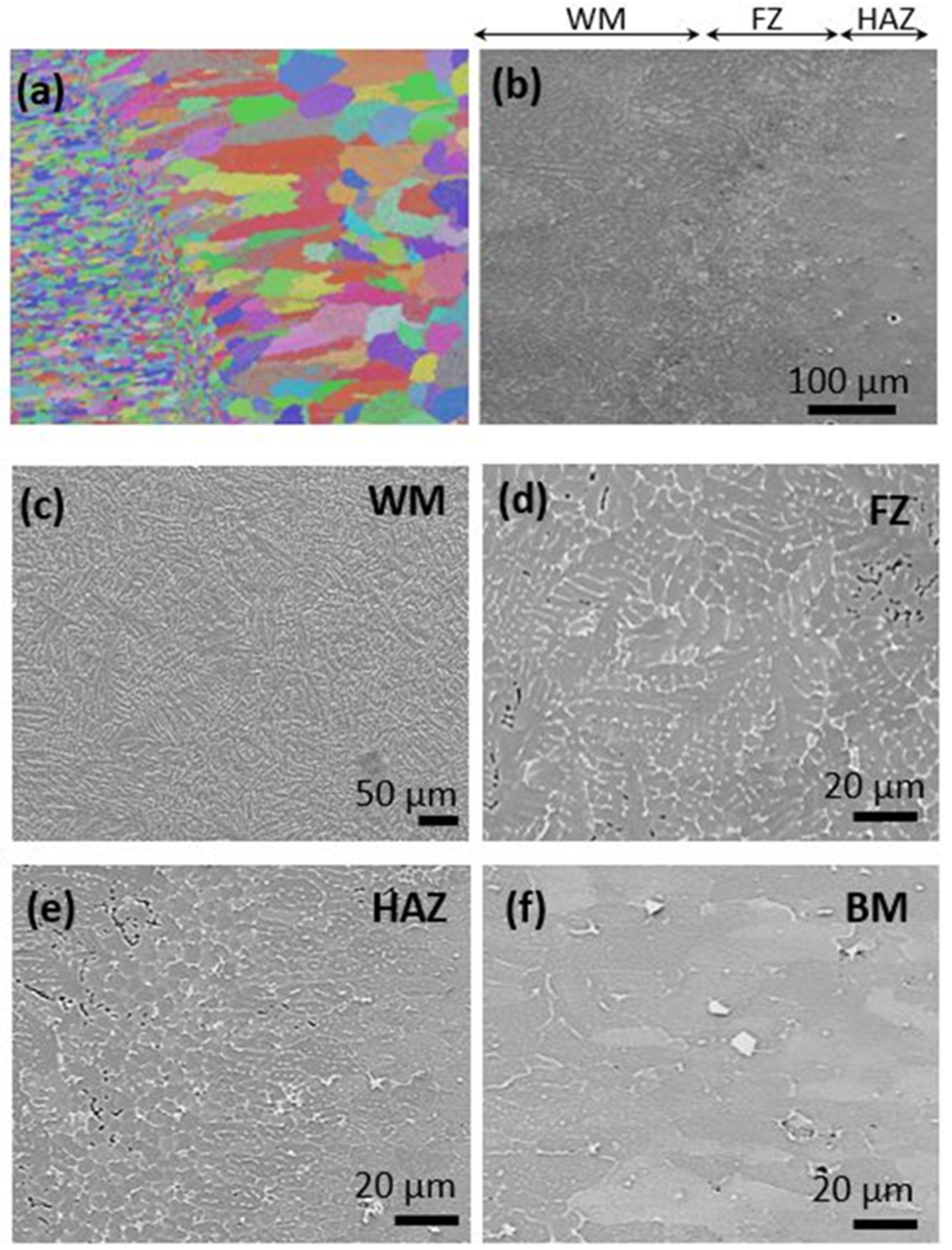
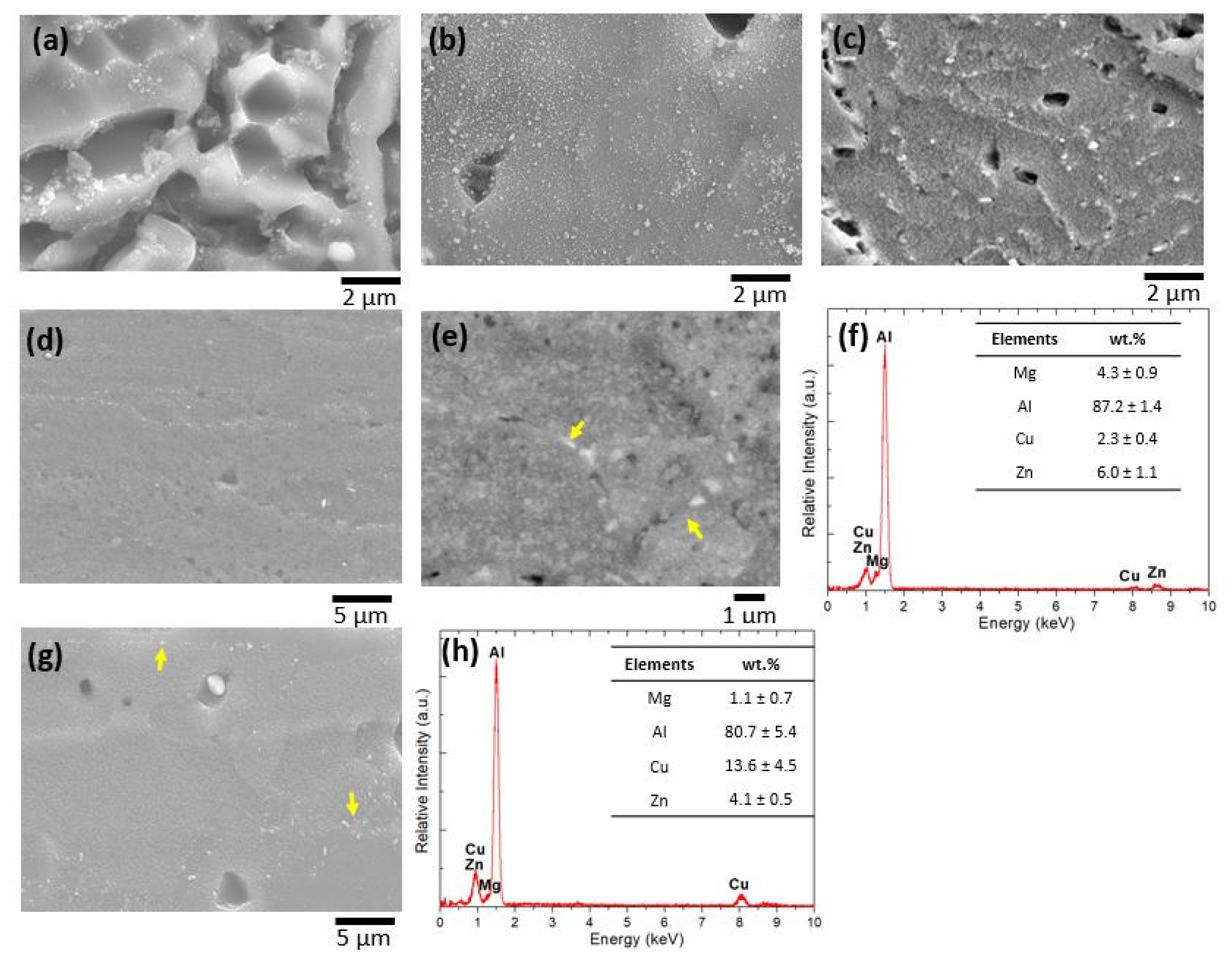
3.2.4. Microstructural Analysis

It is found that the cooling rate related to the quenching media after the PWHT has a significant effect on the mechanical properties. For this reason, the microstructural changes in the welding seam of standard, water-quenched, and air-quenched samples are investigated. In order to understand the microstructural changes in the weld zone, standard samples without heat treatment are investigated first. Figure 16 illustrates the combination of EBSD and SEM images (a,b), showing the microstructural variations along the weld joint of the standard welded sample. The welded zone includes four different typical welding regions, named as weld metal (WM), fusion zone (FZ), heat-affected zone (HAZ) and base material (BM). The enlarged SEM images within WM, FZ, HAZ and BM areas are shown in higher magnification in Figure 16c–f. The predominant microstructure in the WM is the equiaxed dendritic structure. The columnar dendrites, growing along the direction of the temperature gradient, are observed in the FZ. Moreover, the microstructure observed in the HAZ varies from the zone of columnar grains to equiaxed structure in the BM. The detailed investigation of precipitates is described in the following paragraphs.
Figure 17 compares the microstructure of the weld seam for standard, water- quenched and air-quenched samples. It can be seen that the columnar grain structure formed predominantly in the FZ and that equiaxed grains are detected in the WM in all samples. The structure and size of the grains in the WM did not change significantly after the subsequent heat treatment. On the other hand, the columnar grains observed in the FZ of the PWHT sample are more distinguishable compared to the standard sample. As the cooling rate increases, the columnar grain becomes thinner. Moreover, an analysis of the average grain size is performed to understand the effects of PWHT and cooling rate on the mechanical properties of the specimens. The average grain sizes of the WM before and after PWHT are measured by the line intercept method via ImageJ program from EBSD images, Figure 17. It was found that the average grain sizes of standard, water-quenched and air-quenched samples were 93.6 ± 3.2 µm, 74.6 ± 2.2 µm, and 90.8 ± 3.6 µm, respectively. There is a slight difference between the grain size of standard and air-quenched samples although the grain growth is expected to occur after solution annealing. Hassan et al. [27] found that PWHT caused the grain coarsening in the welding zone of high strength Al alloys. On the other hand, in the present study, the short time interval for solution annealing prevents the grain structure from changing. The grain size of the WM of the water-quenched sample decreases by 20% compared to that of the air-quenched sample. The change of the grain size leads to an increase in hardness and strength of the water-quenched sample. These results are consistent with the mechanical test results (Figure 10).
Detailed microstructural analysis is performed by SEM and back-scattered electron (BSE) images taken from the weld zone for standard and PWHT samples (Figure 18). In the WM of the standard sample (Figure 18a) Cu-Zn-Al rich (18.6% Cu, 2.3% Zn, 1.9% Mg, balance Al) coarser structures are encountered. On the other hand, the water-quenched samples contain fine homogenous precipitates (6.2% Cu, 4.3% Zn, 2.6% Mg, balance Al) in the grain. On the contrary, the precipitates in the WM of the air-quenched samples settled along the grain boundaries, which could be the reason for the lower mechanical properties of the air-quenched specimens compared to the water-quenched samples.
In addition, the structure and chemical composition of precipitations in the BM of water-quenched and air-quenched samples are also given in Figure 18. The relatively high number of fine precipitates including Al, Zn, and Mg elements is observed at the grain boundaries of the air-quenched sample indicated with yellow arrows in Figure 18d,e. It is assumed that these precipitates could be MgZn2 phases, as shown by the elemental analysis given in Figure 18f. Bayazid et al. [10] found the MgZn2 phase as precipitates at the grain boundaries of welded AA7075 alloy after aging. Moreover, Zhang et al. [24] found that the precipitates in the BM of the welded sample are mainly ƞ’ (Mg-Zn) phase, which is related to the main hardening phase in the 7XXX aluminum alloy. On the other hand, random precipitated particles were detected in the BM of the water-quenched sample either at the grain boundaries or in the grain, Figure 18g. The evidence of Mg-Al-Cu precipitates can be seen from the EDS results in Figure 18h. Bayazid et al. also found metastable MgAlCu phase precipitating on the welded areas of a cyclic solution-treated AA7075 alloy after aging for 24 h [10]. Therefore, the reason for the higher UTS and hardness of the water-quenched samples (Figure 10 and Figure 14) could be the formation of fine MgAlCu precipitates in the microstructure. It is known that detailed characterization is required to determine the type and morphology of the precipitates in the microstructure, which will be in the scope of future studies. Therefore, it can be concluded that the cooling rate after the PWHT process can influence the formation of precipitates in the microstructure of the welded AA7075 alloy.

4. Conclusions

In this paper, the influence of a short-time solution annealing and aging process after welding of the high strength AA7075 alloy is investigated in terms of mechanical properties and microstructural analysis. Without PWHT, the joint efficiency of the laser welded AA7075 alloy is 52%. PWHT leads to a significant improvement in mechanical properties of laser welded AA7075-T6 alloy. The highest joint efficiency of 76% was achieved after 120 s PWHT with subsequent water-quenching and then aging at 120 °C for 24 h. Even for the solution annealing time of 10 s, the joint efficiency is 72%, showing the potential of short-time solution annealing for inline processes. Besides, it can be concluded that the quenching media directly affects the mechanical properties, with the highest cooling rate required to achieve the highest strength.
Although the short time interval for solution annealing prevents grain growth in the WM, the change in the columnar grain is observed in the FZ of the air-quenched and water-quenched specimens. The water-quenched specimens with a lower grain size compared to the air-quenched and standard specimens exhibit higher strength, which is in good agreement with the results of the hardness and tensile tests. After PWHT, the formation of Mg-Al-Cu and Mg-Zn rich phases along the grain boundaries enhanced the mechanical properties of air-quenched and water-quenched specimens, respectively. Moreover, fracture surface analysis revealed that the PWHT leads to the development of ductile fracture for water- and air quenching.

Author Contributions

Conceptualization, T.S., S.V., S.B. and P.G.; methodology, T.S., S.V., E.B.Ö., M.G., S.B. and P.G.; investigation, T.S., S.V., E.B.Ö., M.G., S.B. and P.G.; data curation, T.S., S.V., E.B.Ö., M.G.; writing—original draft preparation, T.S., S.V., E.B.Ö.; writing—review and editing, T.S., S.V., E.B.Ö., M.G., S.B. and P.G.; visualization, T.S., S.V., E.B.Ö., M.G., S.B. and P.G.; supervision, S.B. and P.G. All authors have read and agreed to the published version of the manuscript.

Funding

The authors are grateful for the support from the Hessen State Ministry for Higher Education, Research and the Arts—Initiative for the Development of Scientific and Economic Excellence (LOEWE) towards conducting ALLEGRO project (Subprojects A1, A2 and A3).

Institutional Review Board Statement

Not applicable.

Informed Consent Statement

Not applicable.

Data Availability Statement

Not applicable.

Acknowledgments

We acknowledge support by the Deutsche Forschungsgemeinschaft (DFG—German Research Foundation) and the Open Access Publishing Fund of Technical University of Darmstadt.

Conflicts of Interest

The authors declare no conflict of interest.

References

  1. Hügel, H.; Rapp, J. Laserschweißeignung von Aluminiumwerkstoffen für Anwendungen im Leichtbau; Vieweg+Teubner Verlag: Wiesbaden, Germany, 1996; ISBN 978-3-519-06226-4. [Google Scholar]
  2. Enz, J. Laser Beam Welding of High-Alloyed Aluminium-Zinc Alloys. Ph.D. Thesis, Technische Universität, Hamburg-Harburg, Germany, 2017. [Google Scholar]
  3. Enz, J.; Riekehr, S.; Ventzke, V.; Kashaev, N. Laser Weldability of Different Al-Zn Alloys and its Improvement. MSF 2015, 828, 389–394. [Google Scholar] [CrossRef] [Green Version]
  4. Verhaeghe, I.G. Achieving Aerospace Standard Porosity Levels When Welding Thin and Thick-Section Aluminium Using Fibre-Delivered Lasers: Executive Summary. Eng.D. Thesis, University of Warwick, Coventry, UK, 2008. [Google Scholar]
  5. Rajakumar, S.; Muralidharan, C.; Balasubramanian, V. Influence of friction stir welding process and tool parameters on strength properties of AA7075-T6 aluminium alloy joints. Mater. Des. 2011, 32, 535–549. [Google Scholar] [CrossRef]
  6. Enz, J.; Riekehr, S.; Ventzke, V.; Huber, N.; Kashaev, N. Fibre laser welding of high-alloyed Al-Zn-Mg-Cu alloys. J. Mater. Processing Technol. 2016, 237, 155–162. [Google Scholar] [CrossRef]
  7. Liu, C.; Northwood, D.O.; Bhole, S.D. Tensile fracture behavior in CO2 laser beam welds of 7075-T6 aluminum alloy. Mater. Des. 2004, 25, 573–577. [Google Scholar] [CrossRef]
  8. Holzer, M.; Zapf, K.; Kroberger, S.; Henkelmann, M.; Mann, V.; Hofmann, K.; Roth, S.; Schmidt, M. Influence of Dual Beam on Process Stability in Laser Beam Welding of High Strength Aluminum Alloy AA 7075. In Proceedings of the Lasers in Manufacturing Conference 2017, Munich, Germany, 26–29 June 2017. [Google Scholar]
  9. Enz, J.; Riekehr, S.; Ventzke, V.; Sotirov, N.; Kashaev, N. Laser Welding of High-strength Aluminium Alloys for the Sheet Metal Forming Process. Procedia CIRP 2014, 18, 203–208. [Google Scholar] [CrossRef] [Green Version]
  10. Bayazid, S.M.; Farhangi, H.; Asgharzadeh, H.; Radan, L.; Ghahramani, A.; Mirhaji, A. Effect of cyclic solution treatment on microstructure and mechanical properties of friction stir welded 7075 Al alloy. Mater. Sci. Eng. A 2016, 649, 293–300. [Google Scholar] [CrossRef]
  11. Sajadifar, S.V.; Moeini, G.; Scharifi, E.; Lauhoff, C.; Böhm, S.; Niendorf, T. On the Effect of Quenching on Postweld Heat Treatment of Friction-Stir-Welded Aluminum 7075 Alloy. J. Mater. Eng. Perform. 2019, 28, 5255–5265. [Google Scholar] [CrossRef]
  12. Sokoluk, M.; Cao, C.; Pan, S.; Li, X. Nanoparticle-enabled phase control for arc welding of unweldable aluminum alloy 7075. Nat. Commun. 2019, 10, 98. [Google Scholar] [CrossRef] [PubMed] [Green Version]
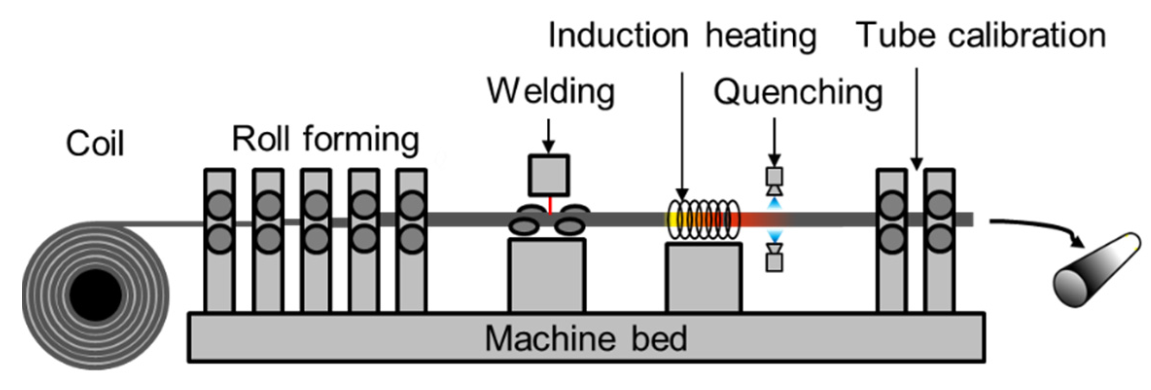
  13. Illia, H.; Viacheslav, B.; Dmytro, R.; Florian, N. Manufacturing of Tailored Tubes with a Process Integrated Heat Treatment. In AIP Conference Proceedings, Proceedings of the 20th International ESAFORM Conference on Material Forming, Dublin, Ireland, 26–28 April 2017; AIP Publishing LLC: Dublin, Ireland, 2017. [Google Scholar]
  14. Nikanorov, A.; Baake, E.; Neumeyer, J. Numerical Simulation and Investigation of High Frequency Tube Welding Process. AMM 2014, 698, 245–250. [Google Scholar] [CrossRef]
  15. Schneider, C.A.; Rasband, W.S.; Eliceiri, K.W. NIH Image to ImageJ: 25 years of image analysis. Nat. Methods 2012, 9, 671–675. [Google Scholar] [CrossRef]
  16. Deutsches Institut für Normung—DIN. Zerstörende Prüfung von Schweißverbindungen an Metallischen Werkstoffen—Querzugversuch; DIN EN ISO 4136; Beuth Verlag GmbH: Berlin, Germany, 2013. [Google Scholar]
  17. Günzel, J.; Hauβ, J.; Groche, P. Temperature-controlled tools for multi-stage sheet metal forming of high-strength aluminium alloys. IOP Conf. Ser. Mater. Sci. Eng. 2021, 1157, 12086. [Google Scholar] [CrossRef]
  18. Tekeli, S.; Simsek, I.; Simsek, D.; Ozyurek, D. Effects of Different Solid Solution Temperatures on Microstructure and Mechanical Properties of the AA7075 Alloy After T6 Heat Treatment. High Temp. Mater. Processes 2019, 38, 892–896. [Google Scholar] [CrossRef]
  19. DIN EN ISO 13919-2; Welding—Electron and Laser Beam Welded Joints—Guidance on Quality Levels for Imperfections—Part 2: Aluminium and Its Weldable Alloys. International Organization for Standardization: Geneva, Switzerland, 2001.
  20. Zou, X.-L.; Yan, H.; Chen, X.-H. Evolution of second phases and mechanical properties of 7075 Al alloy processed by solution heat treatment. Trans. Nonferrous Met. Soc. China 2017, 27, 2146–2155. [Google Scholar] [CrossRef]
  21. Deutsches Institut für Normung—DIN. Wärmebehandlung von Aluminium-Knetlegierungen; DIN 29850; Beuth Verlag GmbH: Berlin, Germany, 1989. [Google Scholar]
  22. Kerstens, N. Nd:YAG Laser Welding of AA7075 High Strength Aluminium; Delft University of Technology: Delft, The Netherlands, 2002. [Google Scholar]
  23. Liu, S.; Zhong, Q.; Zhang, Y.; Liu, W.; Zhang, X.; Deng, Y. Investigation of quench sensitivity of high strength Al–Zn–Mg–Cu alloys by time–temperature-properties diagrams. Mater. Des. 2010, 31, 3116–3120. [Google Scholar] [CrossRef]
  24. Zhang, L.; Li, X.; Nie, Z.; Huang, H.; Sun, J. Microstructure and mechanical properties of a new Al–Zn–Mg–Cu alloy joints welded by laser beam. Mater. Des. 2015, 83, 451–458. [Google Scholar] [CrossRef]
  25. Zhou, M.; Lin, Y.C.; Deng, J.; Jiang, Y.-Q. Hot tensile deformation behaviors and constitutive model of an Al–Zn–Mg–Cu alloy. Mater. Des. 2014, 59, 141–150. [Google Scholar] [CrossRef]
  26. Ashby, M.F. Mechanisms of Deformation and Fracture. In Advances in Applied Mechanics; Elsevier: Amsterdam, The Netherlands, 1983; Volume 23, pp. 117–177. ISBN 9780120020232. [Google Scholar]
  27. Hassan, K.A.A.; Norman, A.F.; Price, D.A.; Prangnell, P.B. Stability of nugget zone grain structures in high strength Al-alloy friction stir welds during solution treatment. Acta Mater. 2003, 51, 1923–1936. [Google Scholar] [CrossRef]
Figure 1. Tube forming process chain with an inline heat treatment process.
Metals 12 00393 g001
Figure 2. Schematic illustration of the experimental setup.
Metals 12 00393 g002
Figure 3. Standard heat treatment parameters for the PWHT.
Metals 12 00393 g003
Figure 4. Heating device and heating curve for a tensile specimen.
Metals 12 00393 g004
Figure 5. Influence of specimen preparation and shielding gas on the UTS of the welding seam.
Metals 12 00393 g005
Figure 6. Influence of welding speed on the UTS of the welding seam.
Metals 12 00393 g006
Figure 7. Optical microscope (OM) image of a welding seam (standard parameters—without heat treatment).
Metals 12 00393 g007
Figure 8. Influence of solution annealing time during PWHT on the UTS of the welding seam.
Metals 12 00393 g008
Figure 9. Cooling rates of different quenching media.
Metals 12 00393 g009
Figure 10. (a) Influence of quenching speed during PWHT on the UTS of the welding seam; (b) Influence of quenching speed on the UTS of the BM.
Metals 12 00393 g010
Figure 11. Stress-strain-curves of the welded and PWHT tensile specimen.
Metals 12 00393 g011
Figure 12. Representative AA7075-T6 welded samples after tensile test: (a) standard sample without heat treatment; (b) water-quenched; (c) air-quenched.
Metals 12 00393 g012
Figure 13. Hardness distribution of the welding seam. Variation of solution annealing time during PWHT.
Metals 12 00393 g013
Figure 14. Hardness distribution of the welding seam. Variation of quenching media during PWHT.
Metals 12 00393 g014
Figure 15. Fracture surfaces of welded AA7075-T6 samples under condition (a,b) standard (no heat treatment); (c,d) water-quenched; (e,f) air-quenched.
Metals 12 00393 g015
Figure 16. (a) EBSD, and (b) SEM images of weld zone of the standard sample, and enlarge SEM images of (c) WM, (d) FZ, (e) HAZ, and (f) BM regions.
Metals 12 00393 g016
Figure 17. Optical microscope and EBSD images of (a,b) standard sample, (c,d) water-quenched, and (e,f) air-quenched samples.
Metals 12 00393 g017
Figure 18. (ac) SEM images of the WM in standard, water-quenched and air-quenched samples, respectively, (d,e) BSE images, and (f) EDS analysis of precipitates detected in the BM of air-quenched, and (g) BSE images and (h) EDS analysis of precipitates detected in the BM water-quenched samples.
Metals 12 00393 g018
Table 1. Chemical composition of the AA7075-T6 alloy.
ElementSiFeCuMnMgCrZnTiZr
Weight [%]0.080.121.60.042.70.195.90.050.04
Table 2. Standard welding parameters.
LaserLaser PowerLaser Spot DiameterBeam Parameter ProductDefocusationWelding AngleShielding Gas
Ytterbium fiber laser3.0 kW400 µm (in focus)8.0 mm × mrad+14 mmArgon
Publisher’s Note: MDPI stays neutral with regard to jurisdictional claims in published maps and institutional affiliations.

