Abstract
Coaxial Laser Metal Deposition with wire (LMD-w) is a valuable complement to the already established Additive Manufacturing processes in production because it allows a direction-independent process with high deposition rates and high deposition accuracy. However, there is a lack of knowledge regarding the adjustment of the process parameters during process development to build defect-free parts. Therefore, in this work, a process development for coaxial LMD-w was conducted using an aluminum wire AlMg4,5MnZr and a stainless steel wire AISI 316L. At first, the boundaries for parameter combinations that led to a defect-free process were identified. The proportion between the process parameters energy per unit length and speed ratio proved crucial for a defect-free process. Then, the influence of the process parameters on the height and width of single beads for both materials was analyzed using a regression analysis. It was shown that linear models are suitable for describing the correlation between the process parameters and the dimensions of the beads. Lastly, a material-independent formula is presented to calculate the height increment per layer needed for an additive process. For future studies, the results of this work will be an aid for process development with different materials.
1. Introduction
1.1. Directed Energy Deposition Processes
In recent years, Directed Energy Deposition (DED) processes have contributed to expand the application fields of metal Additive Manufacturing (AM) [1]. Exemplary applications are coating surfaces by depositing thin material layers, repairing damaged parts by reapplying missing material, and producing freeform parts by gradually depositing multiple layers [2]. Among the distinct advantages of DED processes is the ability to produce large parts at high material deposition rates [3]. The process involves the controlled melting of material fed to the process zone as wire or powder. Using a wire as feedstock offers various advantages over powder use like a facilitated handling, an easy access to standardized feedstock, a higher material usage, higher deposition rates, and an increased operational safety [4,5]. Different systems can be utilized to melt the wire. Wire and Arc Additive Manufacturing (WAAM) processes have the advantage of high deposition rates and are frequently used to build large structures. However, laser-based and electron-based processes allow for a more focused energy supply and are preferably used to manufacture near net shape parts [6]. Laser-based processes, also called Laser Metal Deposition (LMD), with the capacity to accommodate the wire coaxially to the laser beam, provide the additional advantage of a direction-independent process that facilitates their use for AM purposes [7].
Two different solutions have been developed to achieve the coaxial alignment of the supplied feedstock and the laser. Either multiple laser beams are focused on the process zone [8,9,10,11,12], or optical elements are used to form a hollow laser beam with a ring-shaped profile [13,14,15]. All set-ups aim for an almost uniform distribution of the laser radiation around the wire in the process zone to provide the same process conditions for any movement direction. Compared to the process variant with lateral wire feeding, these set-ups contribute to a higher stability and robustness of the process [16].
1.2. State of the Art
1.2.1. Process Development for LMD with Lateral Wire Feeding
In AM, near net shape parts are desired to reduce post-processing efforts [17]. This requires a defect-free process. Studies regarding process development for the Laser Metal Deposition (LMD) with lateral wire feeding can be found in the literature. The processability of different steel [18,19,20,21] and aluminum alloys [22,23,24] was demonstrated through cross-sectional analyses that showed defect-free beads. Within the scope of parameter studies, the influence of different process parameters on the geometry of the bead was evaluated. It was concluded that the laser spot size, the laser power, the wire speed, and the traverse speed have the strongest influence on the geometry of the deposition [19,25]. Further works studied the correlation between several of the mentioned process parameters and the dimensions of the bead through empirical or numerical models [26,27,28,29,30,31,32]. Although the identified correlations show similarities, comparisons and general conclusions are difficult to draw since different systems and parameter ranges were used.
1.2.2. Process Development for LMD with Coaxial Wire Feeding
Researchers also studied the process development for LMD with coaxial wire feeding. The formation mechanisms of the typical process defects—stubbing and dripping—during the coaxial process were analyzed using high-speed imaging [33]. Process defects that occur at the critical stage of the process start could be reduced by placing the wire tip at the beginning of the process directly on the surface of the substrate [34]. Furthermore, it was shown that analogous to the process with lateral wire feeding, the laser power, the traverse speed, and the wire speed have a significant influence on the geometry [35]. Analytical models have been proposed to predict the width and the height of the beads based on the mentioned process parameters [36]. The influence of the unique laser spot shape on the process has also been studied. By changing the focal offset, a positive correlation between an increased size of the laser spot and a wider melt pool could be identified [37,38]. Studies also show that the size of the ring-shaped laser spot can be deliberately used to partially or fully hit the wire before it enters the melt pool when a smaller inner diameter than the diameter of the wire is chosen [39]. Consequently, an additional process parameter, the workpiece illumination proportion (WIP), was proposed to characterize the distribution of the energy applied to the part and the wire [40]. The height of the part plays a crucial role for a defect-free multi-layer process [41] since a non-conformity between the height increment used in the path planning and the actual growth rate of the part would alter the WIP and would lead to process failures. Therefore, closed-loop control solutions have been proposed to adjust the process parameters actively to compensate for height deviations [42,43,44].
1.3. Problem Statement
The review of the relevant literature reveals that a suitable combination of parameters is essential to successfully build parts with coaxial Laser Metal Deposition with wire (LMD-w). Accordingly, dependencies between the process parameters and the resulting deposition were examined. However, the studies were limited to single materials, small parameter ranges, and individual systems. The parameter combinations that led to visibly defect-free test specimens or parts can only restrictively be used for process developments with new materials. A study on the transferability of the findings as an aid for process development is missing. Additionally, the existing approaches considered the height increment during the multi-layer process more as a fixed value rather than an additional process parameter that influences the geometry of the deposition. A more profound knowledge of the dependency between the process parameters and the geometry of the produced part would contribute to improve the quality of the parts [45]. By analyzing these correlations for materials with significantly different properties like the melting temperature, basic trends could be identified that would help during process development with new materials. Furthermore, using the height increment as an additional parameter would assist in understanding the process better and complement the previous studies.
1.4. Objectives and Approach
This contribution aims (i) to investigate correlations between the process boundaries for a coaxial LMD-w process with aluminum and stainless steel, (ii) to develop models through linear regression that allow assessing the influence of the process parameters on the height and width of the beads, and (iii) to investigate the influence of the height increment for each consecutive layer for multi-layer processes. Initially, different parameter combinations were systematically varied to develop process maps that visualized the boundaries of a defect-free process. Then, the dimensions of the successfully deposited beads were measured. This data was subsequently used to perform a regression analysis of the dependence of the bead width and the bead height on the process parameters. Lastly, a formula was developed to calculate the needed height increment for a defect-free multi-layer deposition, and the determined height increment was experimentally tested.
2. Materials, Systems and Methods
2.1. Materials
For the experiments with stainless steel, AISI 304 substrate plates and AISI 316L wire were used. The size of the substrate plates was 100 mm × 100 mm × 10 mm, and the diameter of the wire was 1 mm. The experiments with aluminum were conducted using AlSi1MgMn substrate plates and AlMg4,5MnZr wire with a diameter of 1 mm. The sizes of the substrate plates were 100 mm × 100 mm × 3 mm and 60 mm × 20 mm × 3 mm. The different sizes of the substrate plates for the respective materials resulted from the standard dimensions of the parts provided by the manufacturer. The chemical composition of all the materials is shown in Table 1. Henceforth, the material combinations will be abbreviated as stainless steel and aluminum.

Table 1.
Chemical composition of the materials used within the investigations.
2.2. Systems
2.2.1. Laser Metal Deposition System
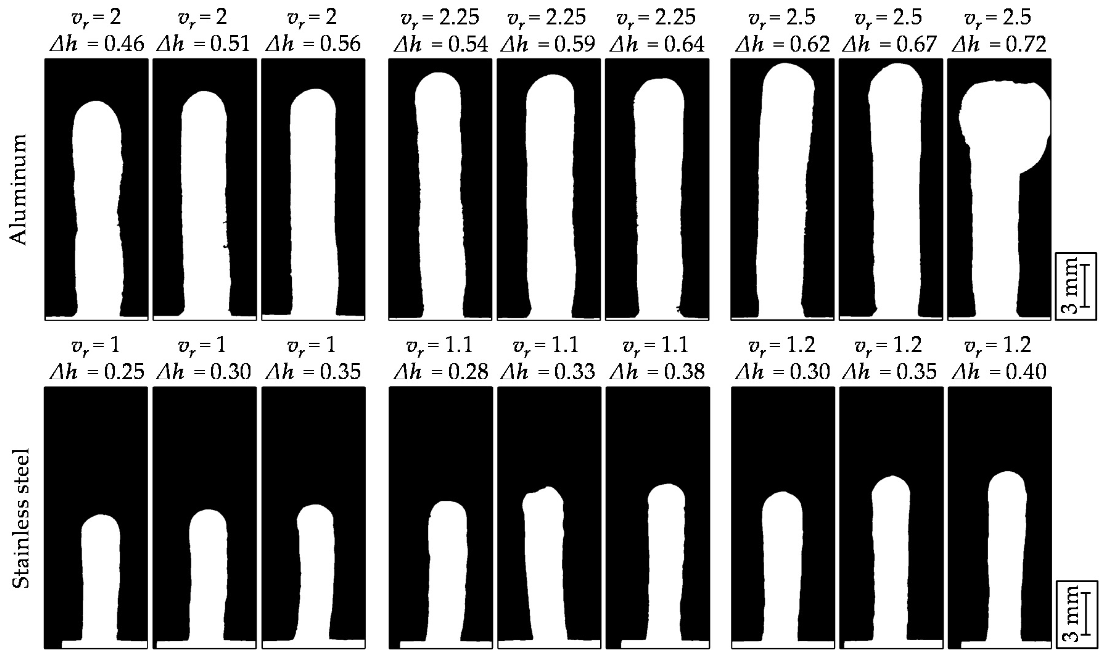
The main system component was the coaxial deposition head (CoaxPrinter, Precitec GmbH & Co. KG, Gaggenau, Germany) that reshaped the laser beam through a combination of axicons to obtain a hollow laser beam which results in a ring-shaped beam profile. The hollow laser beam was then split into two halves allowing the wire to be guided in between. Once the wire and the laser beam were parallelly aligned, the two beam halves were consolidated and focused on the wire. The caustic of the hollow laser beam after the deposition head is depicted in Figure 1a. The focal offset describes the distance between the focal plane and the process plane (surface of the substrate plate). A focal offset of −6 mm with the focus below the surface of the substrate plate was chosen, which resulted in a ring-shaped laser spot with an inside diameter of 1.2 mm and an outside diameter of 2.6 mm at the process plane. A 4-kW disc laser (TruDisk 4001, TRUMPF GmbH & Co. KG, Ditzingen, Germany) generated the laser beam with a wavelength of 1030 nm. The experimental set-up is depicted in Figure 1b. The wire was fed through the deposition head by a wire feeding unit (DIX FDE-PN 100 L, DINSE GmbH, Hamburg, Germany). This unit provided an automatic wire positioning at the beginning and a wire retreat at the end of the process, contributing to the repeatability of the starting and the ending conditions. A 6-axis robot (KR-60, KUKA AG, Augsburg, Germany) with a maximum load capacity of 60 kg and a maximum radial workspace of 2 m was used to carry and move the deposition head. The manufacturer specifies the position repeatability to be 60 µm.
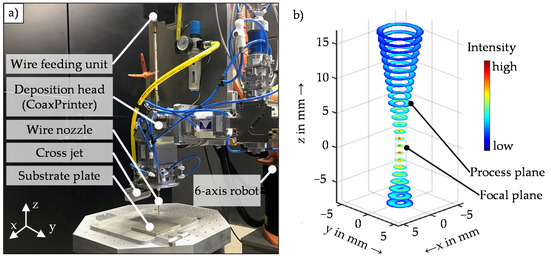
Figure 1.
Experimental set-up: (a) main system components and (b) caustic of the hollow laser beam near the process.
2.2.2. Optical Measurement
A 3-D profilometer (VR 3100, Keyence Corporation, Osaka, Japan) was used for a three-dimensional measurement of the topography of the samples [46]. Multiple images with a 38-fold magnification were taken and automatically stitched together to scan the entire surface of the specimens via the light-section method. The manufacturer indicates a measurement accuracy of 6 µm. The software provided by the manufacturer and a MATLAB script were used to compensate for the thermal distortions of the substrate plates and no additional filters were used [47].
2.3. Methods
2.3.1. Theoretical Considerations
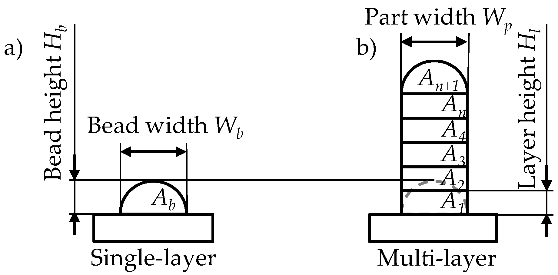
When using LMD-w to fabricate additive parts, the distance between every successively deposited layer and the substrate increases. Therefore, a height increment per layer Δh is needed for path planning. The following assumptions and theoretical equations have been used to calculate the height increment in this work.
The geometry of the cross-section of a weld bead is described by the bead height Hb, the bead width Wb, and the cross-sectional area of a bead Ab (see Figure 2a). The idealized geometry of the cross-section of a part produced by LMD-w consists of a stack of rectangles (see Figure 2b).
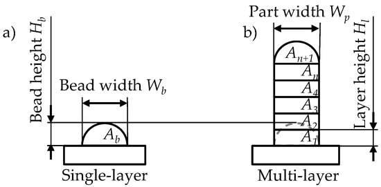
Figure 2.
Schematic cross-sectional geometry of (a) a single-layer (bead) and (b) a multi-layer part.
The idealized width of the part wall Wp was assumed to be equal to Wb. Due to the volume constancy Ab = An, with An being the cross-sectional area of a single layer within the part wall, the height of each layer Hl within the part had to differ from Hb due to the geometry. To calculate Hl, a formula was derived by using the following equations:
The volume of a bead Vb can be calculated using the length of the bead l and the cross-sectional area of a bead Ab by
With the traverse speed vt and the time t, the bead volume deposition rate can be calculated as
The volume of additional material fed to the process VA is equal to the wire volume feeding rate, which can be expressed as
with the diameter of the wire Dw, the wire speed vw, and the cross-sectional area of the wire Aw. Assuming volume constancy, the following equation can be set up:
Using Equations (2) and (3), Equation (4) can be written as
Taking the initial assumption of Ab = An into account, Ab can be replaced by
The resulting equation
can be solved for the variable Hl as
with the speed ratio vr between the wire speed and the traverse speed. In this work, Hl is used as the height increment per layer Δh.
2.3.2. Experimental Procedure
Process Window
First, a process window for single beads was identified. The process was characterized by the laser power (P), the wire speed, and the traverse speed due to the strong influence that these parameters have on the process stability [19,35]. The laser power was kept constant during the experiments at three different levels, and the traverse speed and the wire speed were varied. All the parameter settings are summarized in Table 2. The parameter limits were chosen based on preliminary studies and on literature references [33,42]. For the experiments with aluminum, the highest possible laser power of 3700 W after the optical system was reached due to typical radiation losses, and the maximal wire speed level was set to 8 m min−1 to stay within the range of a reliable wire feeding speed of the wire feeding unit. A shielding gas flow rate of 18 L min−1 was used during the experiments with aluminum and no shielding gas was used in the experiments with stainless steel.
Table 2.
Parameter combinations of the full factorial design used to identify the process window.
Regression Analysis
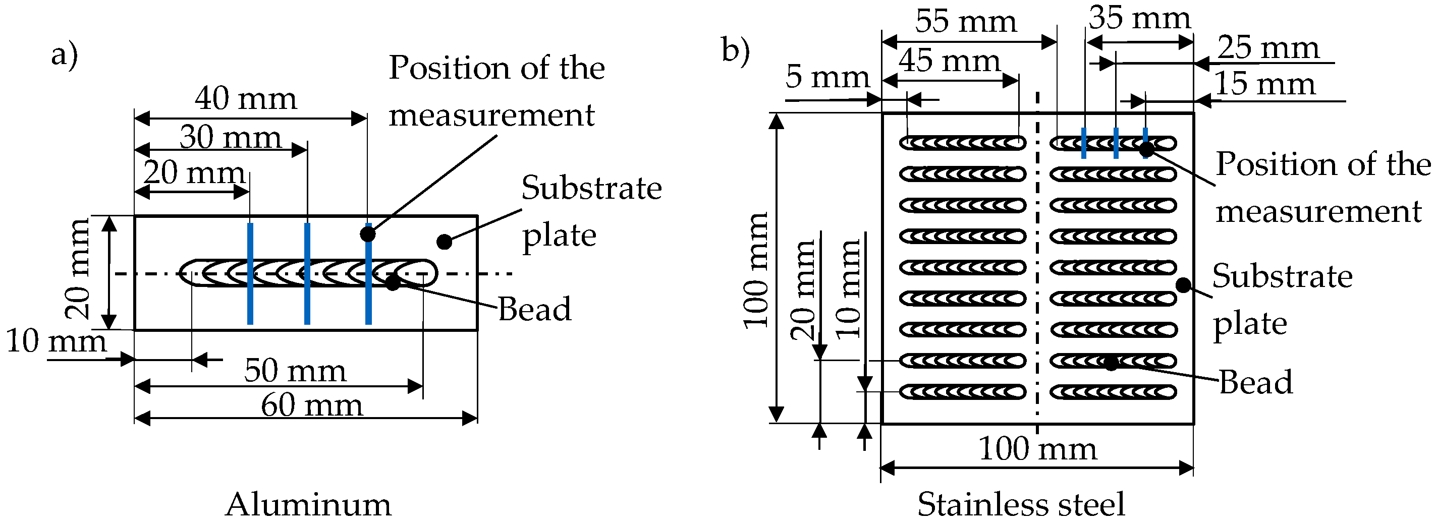
The produced weld beads were evaluated by a visual inspection. The parameter combinations of the defect-free beads were then used to determine the limits for a subsequent parameter study within the process window. A full factorial experimental design was chosen to provide the data for a regression analysis with the dependent variables bead width Wb and bead height Hb, as well as the independent variables laser power, wire speed, and traverse speed. All the parameter settings are summarized in Table 3. In the studies with aluminum, each independent variable was examined on five levels and in the experiments with stainless steel on three. The normalized independent variable values of −1.0, 0, and 1.0 were introduced to compare the results. The natural values of the levels −1.0 and 1.0 were set at the boundary of each process window to examine the most extensive range of the parameter values. The independent variable levels 0 for each parameter of the experiments with aluminum and stainless steel were set in the middle of the inspected process window, which for the aluminum experiments were P = 3400 W, vw = 4 m min−1, vt = 2 m min−1, and for the stainless steel experiments P = 1700 W, vw = 1 m min−1, vt = 1 m min−1. The length of all the beads for the parameter study was 40 mm, and the bead height and width were measured at three positions (see Figure 3).
Table 3.
Process parameters of the full factorial design for the deposition of single beads with subsequent height and width measurement.
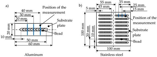
Figure 3.
Schematic visualization of the specimens for the experiments with (a) aluminum and (b) stainless steel.
Height Increment
Lastly, the formula derived in Section 2.3.1 was used to calculate the height increment for the multi-layer processes. All the parameter settings for the experiments can be found in Table 4. Three different speed ratios for each material were examined. The calculated height increment was varied by −0.05 mm and +0.05 mm to analyze the effects of different height increments on the height of the produced cylindrical parts. For all parts, 30 consecutive layers were applied. To avoid an overheating of the parts, a power decay strategy depending on the number of the current layer was chosen based on previous studies and on literature [33,42]. The sample geometries are indicated in Figure 4. In the end, the final height of the produced parts was compared with the theoretically calculated height for the last layer.
Table 4.
Process parameters for the build-up of cylinders.
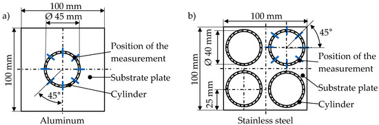
Figure 4.
Schematic depiction of the cylindrical specimens produced with (a) aluminum and (b) stainless steel.
2.3.3. Bead Analysis
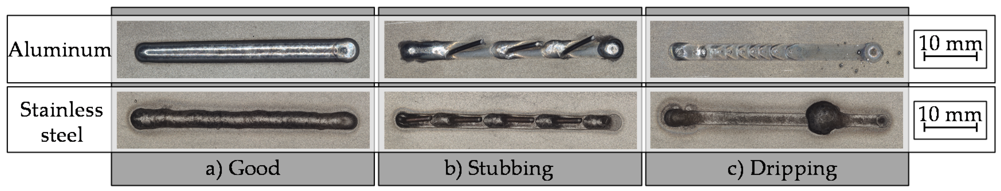
In the visual inspection, the beads were classified into the commonly used categories stubbing, dripping, and good [18,33], as shown by examples for both materials in Figure 5. Stubbing describes the process defect that leads to beads with protuberant short pieces of unmolten wire and is mainly due to an insufficient energy input. Dripping occurs when the induced heat causes the melting of the wire before it hits the surface of the substrate. This is either caused by excessive energy input, an insufficient wire speed, or an inadequate focal offset. If neither of the two errors occurred, the beads were assigned to the category good.
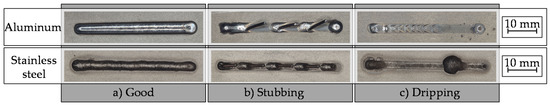
Figure 5.
Categories for the classification using aluminum examples on the upper row and stainless steel examples on the bottom row: (a) good, (b) stubbing, and (c) dripping.
3. Results and Discussion
3.1. Process Windows
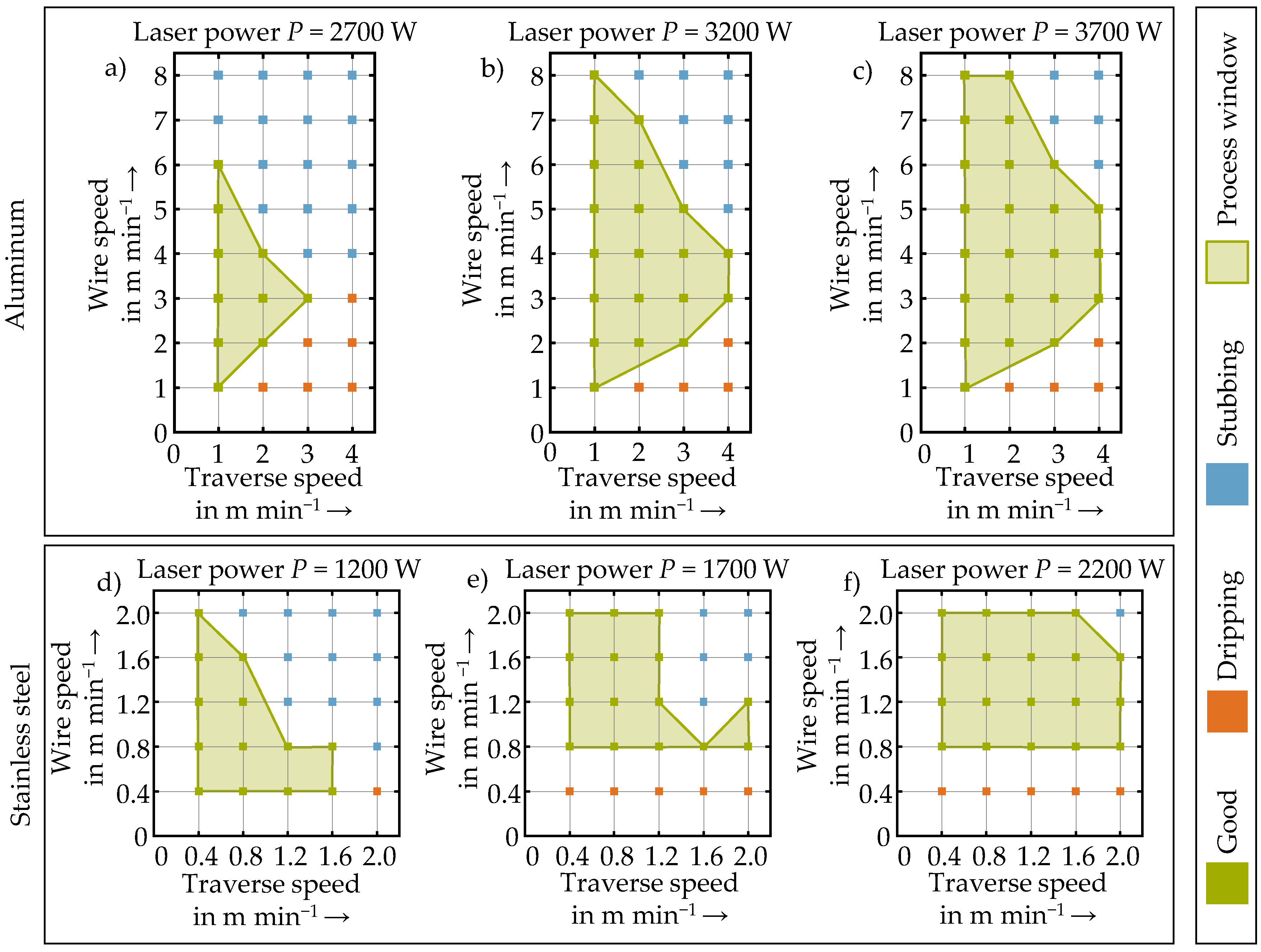
Through experiments, suitable parameter windows for LMD-w with aluminum and stainless steel were identified. The results are summarized in process maps shown in Figure 6. For the inspected ranges of the parameter variations, it can be observed that an increase of the laser power enlarged the process window regarding the variation of the other parameters. Since more energy was applied, either larger quantities of supplied wire could be molten, or higher traverse speeds could be used, especially for aluminum. The processes with a high wire speed and a high traverse speed resulted in stubbing. The higher amount of energy needed to melt the increasing amount of wire was not provided since higher traverse speeds lowered the energy input. Therefore, the unmolten wire was bent due to the traverse movement and eventually mechanically detached, resulting in the remaining stubs [33]. The combination of a low wire speed and a high traverse speed led to dripping. This defect was caused by the melting of the wire above the surface of the substrate plate. Lower wire speeds lead to a prolonged exposure of the wire to both the laser beam and the reflected radiation on the melt pool. Therefore, the wire was more prone to reach the melting temperature above the melt pool. The established bond between molten wire and melt pool broke and a droplet was formed at the tip of the wire due to surface tension [33,40]. The increased traverse speeds reduced the energy input, but they also led to more bending of the wire tip at the initial phase of the process, especially in the experiments with aluminum. This increased the exposed surface of the wire to the laser beam and contributed to a premature melting and, again, the formation of a drop.
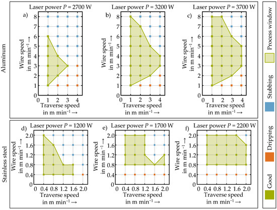
Figure 6.
Determined process maps for aluminum (a–c) and stainless steel (d–f); the values of the fixed laser powers are indicated on top of the respective diagrams.
To compare the process windows for aluminum and stainless steel, a different evaluation is proposed, where the three parameters laser power, wire speed, and traverse speed are combined into the two parameters of the speed ratio and the energy per unit length El (see Figure 7). Based on the diagrams, it can be deduced that for both materials, an adequate ratio between the energy per unit length and the speed ratio was crucial to avoid the defects of dripping and stubbing. This is in accordance with comparable findings in the literature [38]. A higher energy per unit length was required for higher speed ratios to avoid stubbing for both materials. However, it can be noticed that defect-free processes were achieved for higher speed ratios with aluminum than with stainless steel when using the same amount of energy per unit length. For example, with 100 J mm−1 a speed ratio of 3.5 still led to a defect-free process with aluminum, while the maximal speed ratio with this energy per unit length with stainless steel was 2.2. The lower melting temperature of aluminum compared to stainless steel allowed to melt the larger quantities of material that resulted from higher speed ratios with the same amount of energy. However, the higher melting temperature of stainless steel allowed defect-free processes for lower speed ratios than aluminum since the wire had to be heated up more before it melted. For aluminum, speed ratios below 1 mostly led to dripping, while for stainless steel parameter combinations with a speed ratio of 0.5 were found that resulted in good beads. The process maps depicted in Figure 7 are helpful when adjusting the process parameters effectively during process development. For a given speed ratio, the chosen traverse speed can be used to calculate the laser power needed to provide the right amount of energy per unit length to stay within the process window.
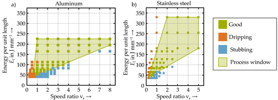
Figure 7.
Determined process maps using the parameters speed ratio and energy per unit length for (a) aluminum and (b) stainless steel.
3.2. Regression Analysis
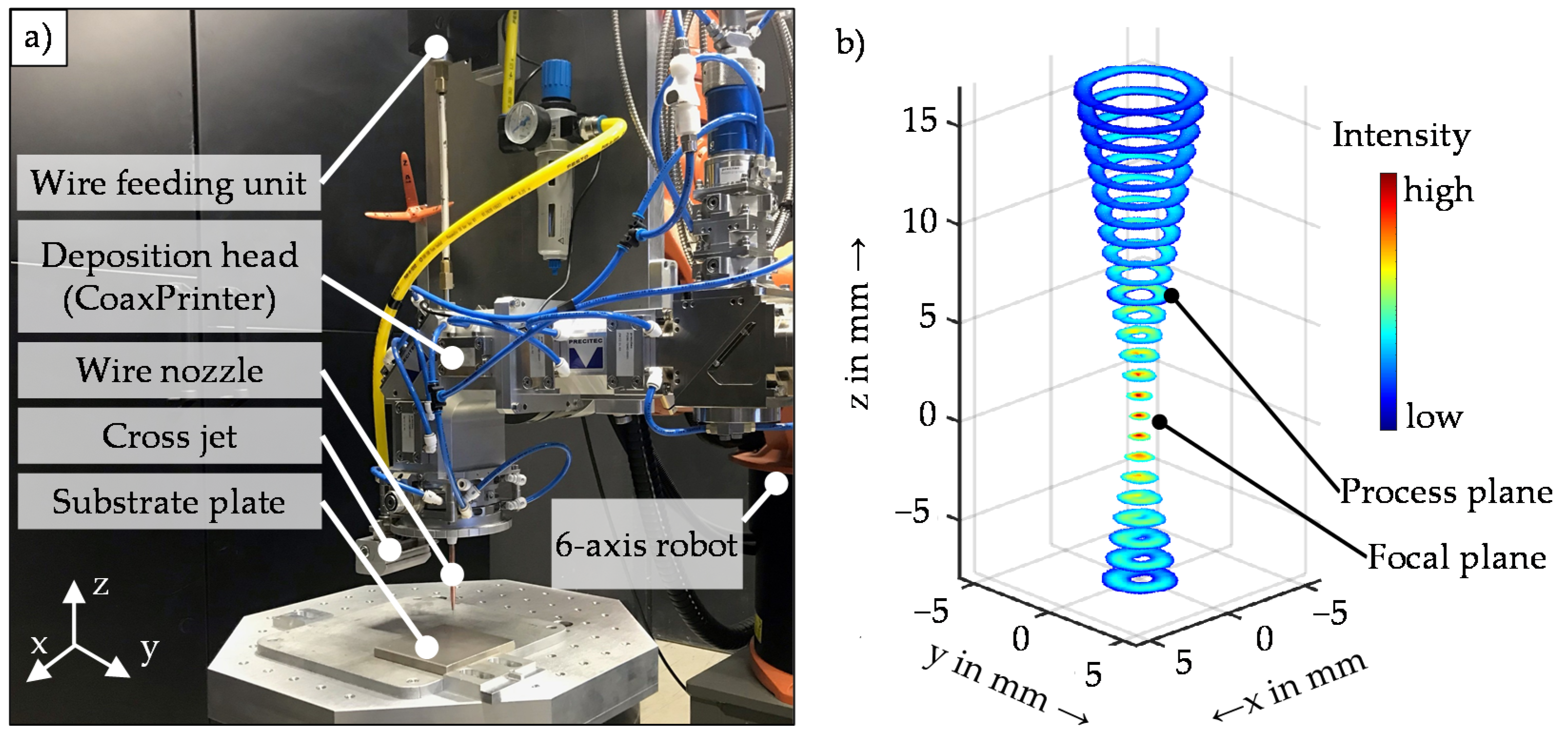
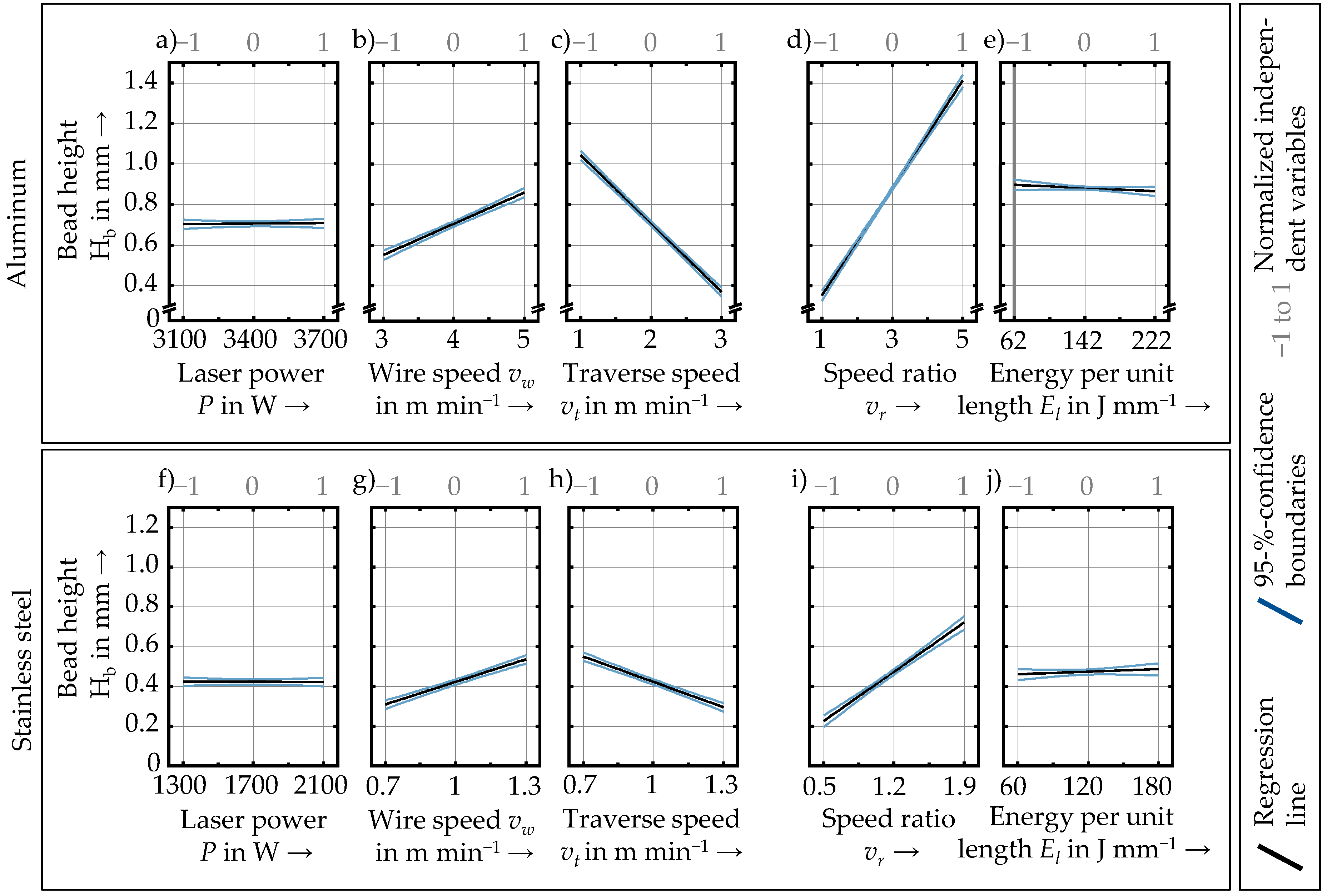
The influence of the process parameters on the bead width and bead height was assessed through a multiple linear regression analysis. In Figure 8, the relationship between the process parameters and the height of the beads for each material is shown. The model coefficients and the results of the analysis of variance (ANOVA) can be found in the Appendix A. Similar trends for the influence of all individual parameters on the bead height for both materials are visible in the diagrams. The influence of the laser power on the bead height was considered statistically insignificant (p-value above 0.05) and was therefore not further analyzed. The increase of the wire speed led to higher beads, while increasing the traverse speed reduced their height by up to 0.6 mm. For both materials, the speed ratio, which combines the two parameters, had the most decisive influence on bead height. The small influence of the laser power on the bead height is also visible in the minor influence of the energy per unit length on the bead height. An adjusted coefficient of determination R2 above 0.9 was calculated for all the models. Comparable R2-values resulted for both the models that used the parameters speed ratio and energy per unit length, as well as the models that used the laser power, the traverse speed, and the wire speed. It was concluded that the bead height could be modeled using either one of both combinations.
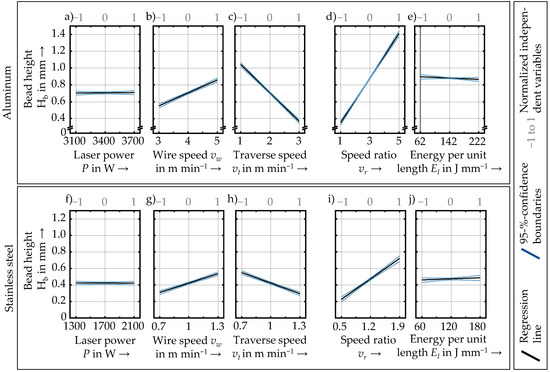
Figure 8.
Main effects of the process parameters on the bead height of aluminum (upper row) and stainless steel (bottom row) samples; the single linear models used the independent variables power, wire speed, and traverse speed (a–c) and (f–h), as well as the independent variables speed ratio and energy per unit length (d,e) and (i,j).
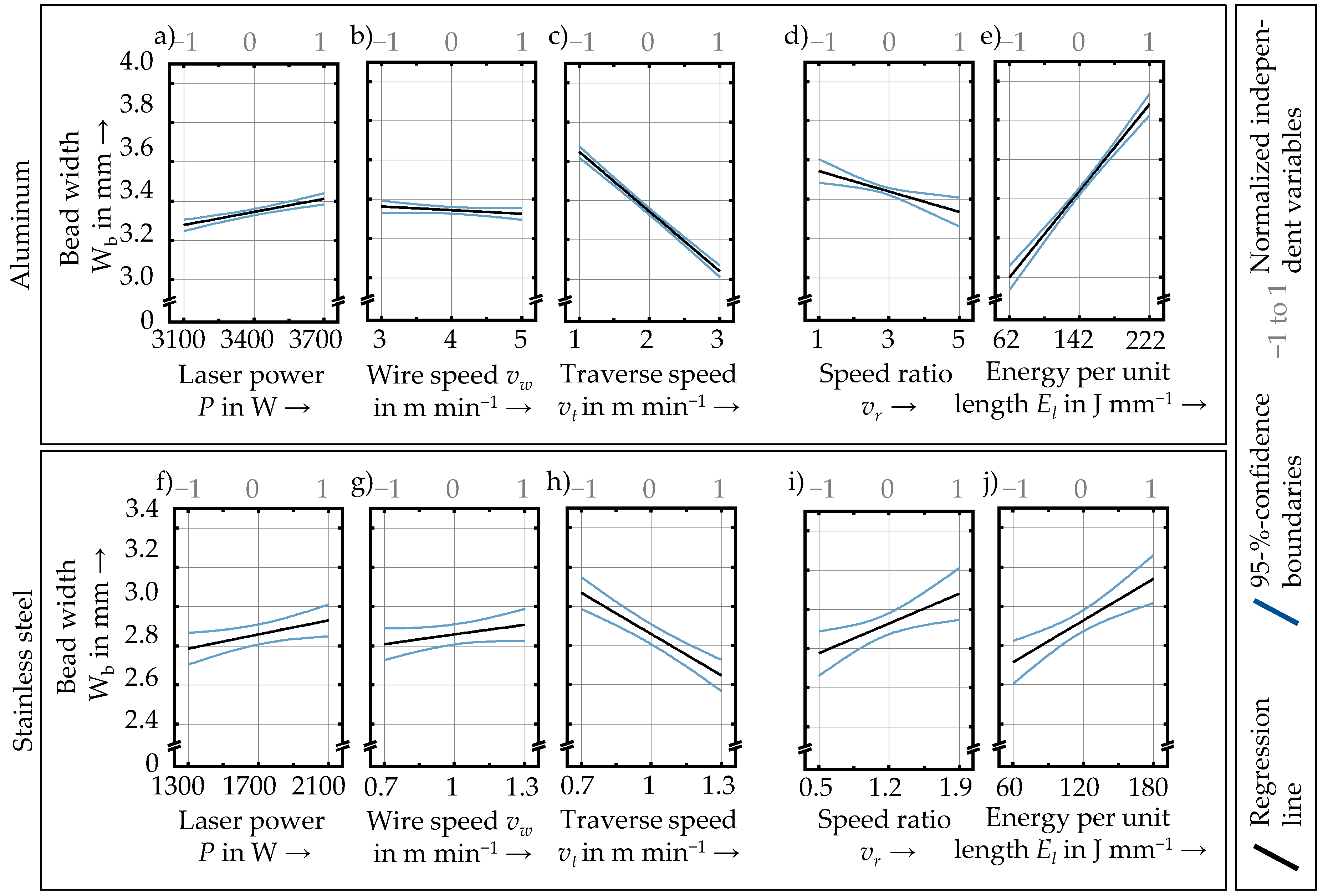
The relationships between the process parameters and the width of the beads for each material are visualized in Figure 9. The diagrams for both materials show similar trends, except for the wire speed and the speed ratio. According to the p-values above 0.05, the influence of the wire speed was considered statistically insignificant and was therefore not further analyzed. The diagrams that visualize the influence of the speed ratio on the bead width show a negative correlation for aluminum and a positive correlation for steel. This deviance in the trends could be due to the different material properties, such as the surface tension, but also due to the different parameter levels chosen for each material. According to the process windows, a speed ratio from 1 to 5 for aluminum and from 0.5 to 1.9 for stainless steel was chosen. Thus, different amounts of material were fed to the process. The energy provided by the laser beam either flows into melting the wire or into melting the substrate. So, for high wire volume feeding rates, such as in the experiments with aluminum, more energy was used for melting the increasing amounts of wire volume, and less energy was available for the melt pool on the substrate. Therefore, the melt pool and bead width decreased. However, for smaller amounts of additional material, especially below a speed ratio of 1, an increase of the wire volume feed rate increased the melt pool volume and led to wider beads [36]. The increased bead width for higher laser power levels and higher levels of energy per unit length could also be explained by changes in the energy balance. The models that described the dependency of the bead width on the process parameters had an acceptable R2 of above 0.84 for aluminum, and for steel above 0.67.
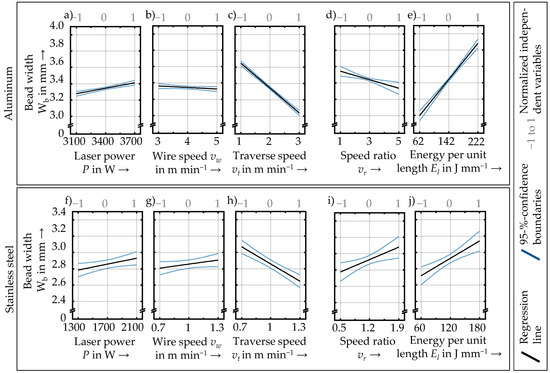
Figure 9.
Main effects of the process parameters on the bead width of aluminum (upper row) and stainless steel (bottom row) samples; the single linear models used the independent variables laser power, wire speed, and traverse speed (a–c) and (f–h) or the independent variables speed ratio and energy per unit length (d,e) and (i,j).
3.3. Height Increment
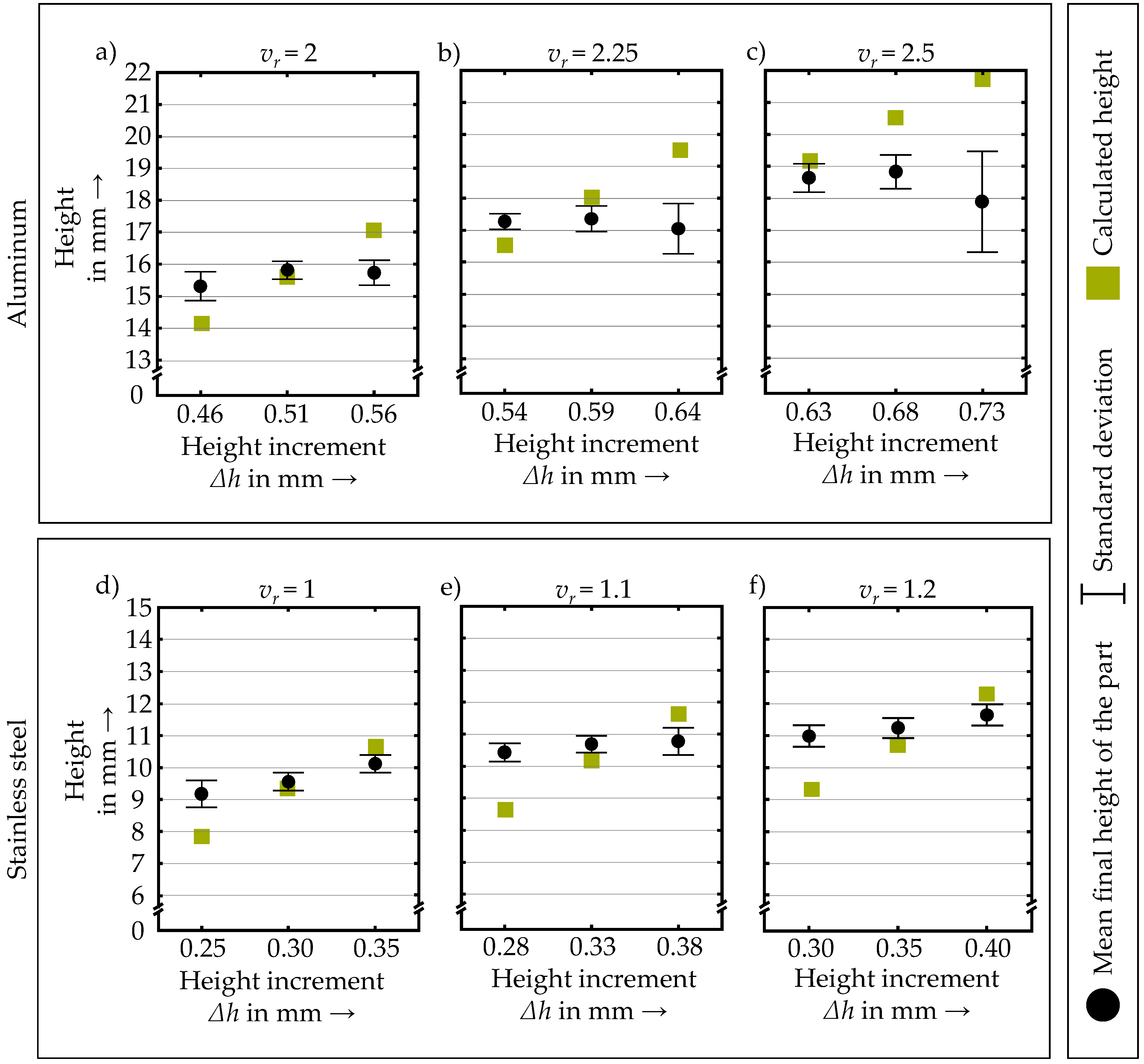
The z-position of the process plane (see Figure 1) must be adjusted by a specific height increment with every successive layer to obtain a constant laser spot size throughout a multi-layer process. To calculate the needed height increment, the formula developed in Section 2.3.1 was used. In Figure 10, the final heights of the cylindrical parts produced with the calculated height increment and the parts produced with the varied height increments of +0.05 mm and −0.05 mm are visualized. The diagrams show that the calculated height of the part is below the measured final height when a smaller height increment than calculated is used. On the contrary, the calculated height of the part is above the measured height when the height increment is greater than the calculated value. In both cases, the deposition of consecutive layers would eventually lead to a process failure due to the discrepancy between the height of the part and the adjusted height of the process plane. Using the theoretically calculated height increment, parts were produced for which the final height closely matched the height of the last process plane, especially with the two lower speed ratios for both materials. The close match means that the height increment was adequate, leading to a defect-free multi-layer process. However, larger deviations were visible at higher speed ratios, especially for the aluminum parts. The deviations could be due to a heat accumulation that resulted from an unsuitable power decay strategy and the different material properties. Since heat accumulation is influenced by the height and the volume of the parts [42], the thermal conditions also changed for the different speed ratios. Higher speed ratios led to more material deposition and more heat accumulation, resulting in a progressively thicker wall [48]. The contour shapes of the cross-sections of the parts are shown in the Appendix A.

Figure 10.
Height of the produced cylinders with a fixed speed ratio as indicated at the top of the respective diagrams and three different height increments for aluminum (a–c) and stainless steel (d–f).
4. Conclusions and Outlook
In this study, the process development for coaxial Laser Metal Deposition with wire was investigated using a stainless steel material combination of AISI 304 substrate plates with AISI 316L wire and an aluminum material combination of AlSi1MgMn substrate plates and AlMg4,5MnZr wire. First, a process window was identified for both material combinations. Then, the influence of the process parameters laser power, wire speed, and traverse speed on the geometry of the depositions was studied. Lastly, the influence of the height increment per layer on the produced parts was analyzed to use the process for Additive Manufacturing purposes. The following conclusions were drawn based on the results of the investigations conducted:
- A suitable combination between the speed ratio and the energy per unit length plays a crucial role in establishing a defect-free process. Therefore, these parameters offer a material-independent valid alternative to the more widely used parameters of the laser power, wire speed, and traverse speed for process development. For both materials, the minimal amount of energy per unit length for a defect-free process was 50 J mm−1. Due to the lower melting temperature of aluminum, a defect-free process could only be achieved using speed ratios above 1, while lower speed ratios resulted in a defect-free process with stainless steel.
- The correlation between process parameters and the bead width and height for both investigated materials can be approximated by linear models.
- Independent of the used material, the following observations regarding the influence of parameter variations within the respective process windows on the bead height and width were made:
- ○
- The bead height increases with higher wire speeds and speed ratios, decreases for higher traverse speeds, and is not affected by the laser power nor the energy per unit length.
- ○
- The bead width increases with a higher laser power and energy per unit length, decreases with higher traverse speeds, and is marginally affected by the wire speed. A higher speed ratio leads to narrower beads for aluminum and wider beads for stainless steel.
- The height increment required for a layer-wise additive process can be chosen based on the presented formula that uses the dimensions of the wire, the speed ratio, and the width of single beads.
In future research, the identified process windows will be further studied to enhance the production efficiency of the process. Based on the presented correlations, the process parameters will be deliberately adapted to improve and to optimize the quality of the produced parts. To further qualify the process for a broad industrial application, an in-depth study of the mechanical and microstructural properties of the parts produced will be conducted in future work. Moreover, thermal models will be developed to predict the temperature fields that result from the process and thus help better comprehend the effects of the process on the produced parts. Furthermore, the production of more complex geometries requires attention. For example, a constant traverse speed is often not given at turning points. Therefore, solutions are needed to cope with the effects that abrupt changes in the traverse speed have on the resulting geometry of the part.
Author Contributions
Conceptualization, A.Z. and C.B.; methodology, A.Z. and C.B.; validation, A.Z.; formal analysis, A.Z.; investigation, A.Z.; resources, M.F.Z.; data curation, A.Z.; writing—original draft preparation, A.Z.; writing—review and editing, A.Z., C.B., C.S., C.G.K. and M.F.Z.; visualization, A.Z.; supervision, M.F.Z.; project administration, A.Z.; funding acquisition, M.F.Z. All authors have read and agreed to the published version of the manuscript.
Funding
This research was funded by the German Federal Ministry of Education and Research (BMBF) and supervised by the Projektträger Karlsruhe (PTKA) within the KORESIL project with the grant number 02P20Z002. We thank both institutions for their support and their confidence in us.
Data Availability Statement
Data sharing is not applicable.
Acknowledgments
This study was carried out using systems provided by the Precitec GmbH & Co. KG and the DINSE GmbH. We thank both partners for entrusting us with the systems as well as the great cooperation.
Conflicts of Interest
The authors declare no conflict of interest.
Appendix A
Table A1.
Results of the ANOVA for the individual regression models.
Table A1.
Results of the ANOVA for the individual regression models.
| Dependent Variable | Material | R2 of the Model | SSR | SSE | Independent Variable | Variable Value | Standard Error | p-Value |
|---|---|---|---|---|---|---|---|---|
| Height | Aluminum | 0.92 | 8.57 | 0.69 | P | 7.75 × 10⁻⁶ | 3.17 × 10⁻⁵ | 0.81 |
| vt | −0.34 | 9.51 × 10⁻³ | 1.06 × 10−65 | |||||
| vw | 0.15 | 9.51 × 10⁻³ | 4.61 × 10⁻³² | |||||
| 0.98 | 9.10 | 0.15 | vr | 0.26 | 6.77 × 10⁻³ | 6.39 × 10−71 | ||
| El | −0.19 × 10⁻³ | 0.14 × 10⁻³ | 0.18 | |||||
| Stainless steel | 0.94 | 0.53 | 0.02 | P | −2.25 × 10⁻⁶ | 1.96 × 10⁻⁵ | 0.90 | |
| vt | −0.42 | 0.03 | 3.97 × 10⁻¹⁴ | |||||
| vw | 0.38 | 0.03 | 4.42 × 10⁻¹³ | |||||
| 0.95 | 0.53 | 0.02 | vr | 0.35 | 0.02 | 1.65 × 10⁻¹⁵ | ||
| El | 0.21 × 10⁻³ | 0.21 × 10⁻³ | 0.33 | |||||
| Width | Aluminum | 0.84 | 6.10 | 1.11 | P | 0.22 × 10⁻³ | 4.04 × 10⁻³ | 1.53 × 10⁻⁷ |
| vt | −0.30 | 0.01 | 7.62 × 10−50 | |||||
| vw | −0.018 | 0.01 | 0.14 | |||||
| 0.87 | 6.30 | 0.91 | vr | −0.05 | 0.02 | 1.87 × 10⁻³ | ||
| El | 5.53 × 10⁻³ | 0.35 × 10⁻³ | 3.18 × 10⁻³ | |||||
| Stainless steel | 0.67 | 0.93 | 0.37 | P | 0.17 × 10⁻³ | 7.56 × 10⁻⁵ | 0.03 | |
| vt | −0.70 | 0.10 | 4.41 × 10⁻⁷ | |||||
| vw | 0.17 | 0.10 | 0.11 | |||||
| 0.68 | 0.93 | 0.38 | vr | 0.22 | 0.07 | 8.92 × 10⁻³ | ||
| El | 3.50 × 10⁻³ | 0.83 × 10⁻³ | 0.27 × 10⁻³ |
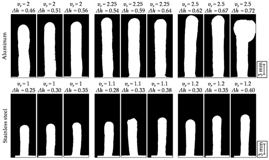
Figure A1.
Cross-sectional profiles of the parts produced with different speed ratios and different height increments.
Figure A1.
Cross-sectional profiles of the parts produced with different speed ratios and different height increments.
References
- Sames, W.J.; List, F.A.; Pannala, S.; Dehoff, R.R.; Babu, S.S. The metallurgy and processing science of metal additive manufacturing. Int. Mater. Rev. 2016, 61, 315–360. [Google Scholar] [CrossRef]
- Gu, D.D.; Meiners, W.; Wissenbach, K.; Poprawe, R. Laser additive manufacturing of metallic components: Materials, processes and mechanisms. Int. Mater. Rev. 2012, 57, 133–164. [Google Scholar] [CrossRef]
- DebRoy, T.; Wei, H.L.; Zuback, J.S.; Mukherjee, T.; Elmer, J.W.; Milewski, J.O.; Beese, A.M.; Wilson-Heid, A.; De, A.; Zhang, W. Additive manufacturing of metallic components—Process, structure and properties. Prog. Mater. Sci. 2018, 92, 112–224. [Google Scholar] [CrossRef]
- Ding, D.; Pan, Z.; Cuiuri, D.; Li, H. Wire-feed additive manufacturing of metal components: Technologies, developments and future interests. Int. J. Adv. Manuf. Technol. 2015, 81, 465–481. [Google Scholar] [CrossRef]
- Maderieta, M.; Leunda, J.; Garmendia, I.; Soriano, C. Compartive study of laser metal deposition (LMD) of coaxial wire and powder in the manufacture of Ti-6AL-4V structures. DYNAII 2020, 95, 376–379. [Google Scholar] [CrossRef]
- Dass, A.; Moridi, A. State of the Art in Directed Energy Deposition: From Additive Manufacturing to Materials Design. Coatings 2019, 9, 418. [Google Scholar] [CrossRef] [Green Version]
- Syed, W.U.H.; Li, L. Effects of wire feeding direction and location in multiple layer diode laser direct metal deposition. Appl. Surf. Sci. 2005, 248, 518–524. [Google Scholar] [CrossRef]
- Shakhverdova, I.; Nowotny, S.; Thieme, S.; Kubisch, F.; Beyer, E.; Leyens, C. Coaxial Laser Wire Deposition. J. Phys. Conf. Ser. 2018, 1109, 12026. [Google Scholar] [CrossRef]
- Pajukoski, H.; Näkki, J.; Thieme, S.; Tuominen, J.; Nowotny, S.; Vuoristo, P. High performance corrosion resistant coatings by novel coaxial cold- and hot-wire laser cladding methods. J. Laser Appl. 2016, 28, 12011. [Google Scholar] [CrossRef]
- Bambach, M.; Sizova, I.; Silze, F.; Schnick, M. Comparison of laser metal deposition of Inconel 718 from powder, hot and cold wire. Procedia CIRP 2018, 74, 206–209. [Google Scholar] [CrossRef]
- Du, F.; Zhu, J.; Ding, X.; Zhang, Q.; Ma, H.; Yang, J.; Cao, H.; Ling, Z.; Wang, G.; Duan, X.; et al. Dimensional characteristics of Ti-6Al-4V thin-walled parts prepared by wire-based multi-laser additive manufacturing in vacuum. Rapid Prototyp. J. 2019, 25, 849–856. [Google Scholar] [CrossRef]
- Lammers, M.; Biester, K.; Schwarz, N.; Hermsdorf, J.; Kaierle, S.; Ahlers, H. Automatic changing of weld deposit for additive manufacturing of hybrid metal-glass components using direct laser deposition. In Proceedings of the Lasers in Manufacturing Conference 2021, Munich, Germany, 21–24 June 2021. [Google Scholar]
- Kelbassa, J.; Gasser, A.; Bremer, J.; Pütsch, O.; Poprawe, R.; Henrich Schleifenbaum, J. Equipment and process windows for laser metal deposition with coaxial wire feeding. J. Laser Appl. 2019, 31, 22320. [Google Scholar] [CrossRef]
- Kuznetsov, A.; Jeromen, A.; Levy, G.; Fujishima, M.; Govekar, E. Annular Laser Beam Cladding Process Feasibility Study. Phys. Procedia 2016, 83, 647–656. [Google Scholar] [CrossRef] [Green Version]
- Liu, S.; Kong, F.; Shi, S.; Kovacevic, R. Study of a hollow laser beam for cladding. Int. J. Adv. Manuf. Technol. 2014, 73, 147–159. [Google Scholar] [CrossRef]
- Govekar, E.; Jeromen, A.; Kuznetsov, A.; Kotar, M.; Kondo, M. Annular laser beam based direct metal deposition. Procedia CIRP 2018, 74, 222–227. [Google Scholar] [CrossRef]
- Nowotny, S.; Scharek, S.; Beyer, E.; Richter, K.-H. Laser Beam Build-Up Welding: Precision in Repair, Surface Cladding, and Direct 3D Metal Deposition. J. Therm. Spray. Tech. 2007, 16, 344–348. [Google Scholar] [CrossRef]
- Abioye, T.E.; Medrano-Tellez, A.; Farayibi, P.K.; Oke, P.K. Laser metal deposition of multi-track walls of 308LSi stainless steel. Mater. Manuf. 2017, 32, 1660–1666. [Google Scholar] [CrossRef]
- Medrano, A.; Folkes, J.; Segal, J.; Pashby, I. Fibre laser metal deposition with wire: Parameters study and temperature monitoring system. In Proceedings of the XVII International Symposium on Gas Flow, Chemical Lasers, and High-Power Lasers, Lisboa, Portugal, 15–19 September 2008. [Google Scholar]
- Oliari, S.H.; D’Oliveira, A.S.C.M.; Schulz, M. Additive Manufacturing of H11 with Wire-Based Laser Metal Deposition. Soldag. Insp. 2017, 22, 466–479. [Google Scholar] [CrossRef] [Green Version]
- Akbari, M.; Ding, Y.; Kovacevic, R. Process Development for a Robotized Laser Wire Additive Manufacturing. In Proceedings of the ASME 2017, Los Angeles, CA, USA, 3–9 November 2017. [Google Scholar]
- Silva, A.D.; Wang, S.; Volpp, J.; Kaplan, A.F.H. Vertical laser metal wire deposition of Al-Si alloys. Procedia CIRP 2020, 94, 341–345. [Google Scholar] [CrossRef]
- Froend, M.; Riekehr, S.; Kashaev, N.; Klusemann, B.; Enz, J. Process development for wire-based laser metal deposition of 5087 aluminium alloy by using fibre laser. J. Manuf. Process. 2018, 34, 721–732. [Google Scholar] [CrossRef]
- Valentin, M.; Arnaud, C.; Kling, R. Additive manufacturing by wire based laser metal deposition. In Proceedings of the Laser 3D Manufacturing VI, San Francisco, CA, USA, 5–7 February 2019. [Google Scholar]
- Barroi, A.; Hermsdorf, J.; Kaierle, S.; Overmeyer, L. Influence of scan width and wire feed speed on seam geometry and the substrate surface in laser wire cladding. In Proceedings of the International Congress on Applications of Lasers & Electro-Optics ICALEO®, San Diego, CA, USA, 16–20 October 2016. [Google Scholar]
- Hu, R.; Luo, M.; Liu, T.; Liang, L.; Huang, A.; Trushnikov, D.; Karunakaran, K.P.; Pang, S. Thermal fluid dynamics of liquid bridge transfer in laser wire deposition 3D printing. Sci. Technol. Weld. Join. 2019, 24, 401–411. [Google Scholar] [CrossRef]
- Shaikh, M.O.; Chen, C.-C.; Chiang, H.-C.; Chen, J.-R.; Chou, Y.-C.; Kuo, T.-Y.; Ameyama, K.; Chuang, C.-H. Additive manufacturing using fine wire-based laser metal deposition. Rapid Prototyp. J. 2019, 26, 473–483. [Google Scholar] [CrossRef]
- Caiazzo, F. Additive manufacturing by means of laser-aided directed metal deposition of titanium wire. Int. J. Adv. Manuf. Technol. 2018, 96, 2699–2707. [Google Scholar] [CrossRef] [Green Version]
- Mok, S.H.; Bi, G.; Folkes, J.; Pashby, I. Deposition of Ti–6Al–4V using a high power diode laser and wire, Part I: Investigation on the process characteristics. Surf. Coat. Technol. 2008, 202, 3933–3939. [Google Scholar] [CrossRef]
- Huang, W.; Chen, S.; Xiao, J.; Jiang, X.; Jia, Y. Laser wire-feed metal additive manufacturing of the Al alloy. Opt. Laser Technol. 2021, 134, 106627. [Google Scholar] [CrossRef]
- Demir, A.G. Micro laser metal wire deposition for additive manufacturing of thin-walled structures. Opt. Lasers Eng. 2018, 100, 9–17. [Google Scholar] [CrossRef]
- Mbodj, N.G.; Abuabiah, M.; Plapper, P.; El Kandaoui, M.; Yaacoubi, S. Bead Geometry Prediction in Laser-Wire Additive Manufacturing Process Using Machine Learning: Case of Study. Appl. Sci. 2021, 11, 11949. [Google Scholar] [CrossRef]
- Motta, M.; Demir, A.G.; Previtali, B. High-speed imaging and process characterization of coaxial laser metal wire deposition. Addit. Manuf. 2018, 22, 497–507. [Google Scholar]
- Kotar, M.; Fujishima, M.; Levy, G.; Govekar, E. Initial transient phase and stability of annular laser beam direct wire deposition. CIRP Ann. 2019, 68, 233–236. [Google Scholar] [CrossRef]
- Wang, Y.K.; Shi, S.H.; Fu, G.Y.; Li, C.S. Research on the Key Process Parameters in Direct Laser Deposition Using Coaxial Inside-Beam Wire Feeding. Appl. Mech. Mater. 2010, 43, 401–404. [Google Scholar]
- Shi, J.; Zhu, P.; Fu, G.; Shi, S. Geometry characteristics modeling and process optimization in coaxial laser inside wire cladding. Opt. Laser Technol. 2018, 101, 341–348. [Google Scholar] [CrossRef]
- Kelbassa, J.; Biber, A.; Wissenbach, K.; Loosten, J.H.; Gasser, A.; Pütsch, O.; Loosen, P.; Schleifenbaum, J. Influence of focal length on the laser metal deposition process with coaxial wire feeding. In Proceedings of the High-Power Laser Materials Processing: Applications, Diagnostics, and Systems VIII, San Francisco, CA, USA, 2–7 February 2019. [Google Scholar]
- Ji, S.; Liu, F.; Shi, T.; Fu, G.; Shi, S. Effects of Defocus Distance on Three-Beam Laser Internal Coaxial Wire Cladding. Chin. J. Mech. Eng. 2021, 34, 1–22. [Google Scholar] [CrossRef]
- Govekar, E.; Kuznetsov, A.; Jerič, A. Drop on demand generation from a metal wire by means of an annular laser beam. J. Mater. Process. Technol. 2016, 227, 59–70. [Google Scholar] [CrossRef] [Green Version]
- Kotar, M.; Govekar, E. The influence of the workpiece illumination proportion in annular laser beam wire deposition process. Procedia CIRP 2018, 74, 228–232. [Google Scholar] [CrossRef]
- Donadello, S.; Motta, M.; Demir, A.G.; Previtali, B. Coaxial laser triangulation for height monitoring in laser metal deposition. Procedia CIRP 2018, 74, 144–148. [Google Scholar] [CrossRef]
- Becker, D.; Boley, S.; Eisseler, R.; Stehle, T.; Möhring, H.-C.; Onuseit, V.; Hoßfeld, M.; Graf, T. Influence of a closed-loop controlled laser metal wire deposition process of S Al 5356 on the quality of manufactured parts before and after subsequent machining. Prod. Eng. Res. Dev. 2021, 15, 489–507. [Google Scholar] [CrossRef]
- Garmendia, I.; Pujana, J.; Lamikiz, A.; Madarieta, M.; Leunda, J. Structured light-based height control for laser metal deposition. J. Manuf. Process. 2019, 42, 20–27. [Google Scholar] [CrossRef]
- Wu, M.J.; Shi, S.H.; Fu, G.Y.; Liu, Y. Process Parameters Control of Deposition of Hollow Cylindrical Part with Internal Wire Feeding through a Hollow Laser Beam. Appl. Mech. Mater. 2013, 419, 305–309. [Google Scholar] [CrossRef]
- Leyens, C.; Beyer, E. Innovations in laser cladding and direct laser metal deposition. In Laser Surface Engineering; Lawrence, J., Waugh, D.G., Eds.; Woodhead Publishing: Sawston, Cambridge, UK, 2015; pp. 181–192. [Google Scholar]
- Townsend, A.; Senin, N.; Blunt, L.; Leach, R.K.; Taylor, J.S. Surface texture metrology for metal additive manufacturing: A review. Precis. Eng. 2016, 46, 34–47. [Google Scholar] [CrossRef] [Green Version]
- Nagalingam, A.P.; Vohra, M.S.; Kapur, P.; Yeo, S.H. Effect of Cut-Off, Evaluation Length, and Measurement Area in Profile and Areal Surface Texture Characterization of As-Built Metal Additive Manufactured Components. Appl. Sci. 2021, 11, 5089. [Google Scholar] [CrossRef]
- Flores, J.O.N.; Garmendia Saez, I.; Cabanes Axpe, I. Thermal monitoring and control by infrared camera in the manufacture of parts with laser metal deposition. DYNAII 2020, 95, 360–364. [Google Scholar] [CrossRef]


Publisher’s Note: MDPI stays neutral with regard to jurisdictional claims in published maps and institutional affiliations. |
© 2022 by the authors. Licensee MDPI, Basel, Switzerland. This article is an open access article distributed under the terms and conditions of the Creative Commons Attribution (CC BY) license (https://creativecommons.org/licenses/by/4.0/).