
Casting Defects in Sand-Mold Cast Irons—An Illustrated Review with Emphasis on Spheroidal Graphite Cast Irons


Abstract
:1. Introduction
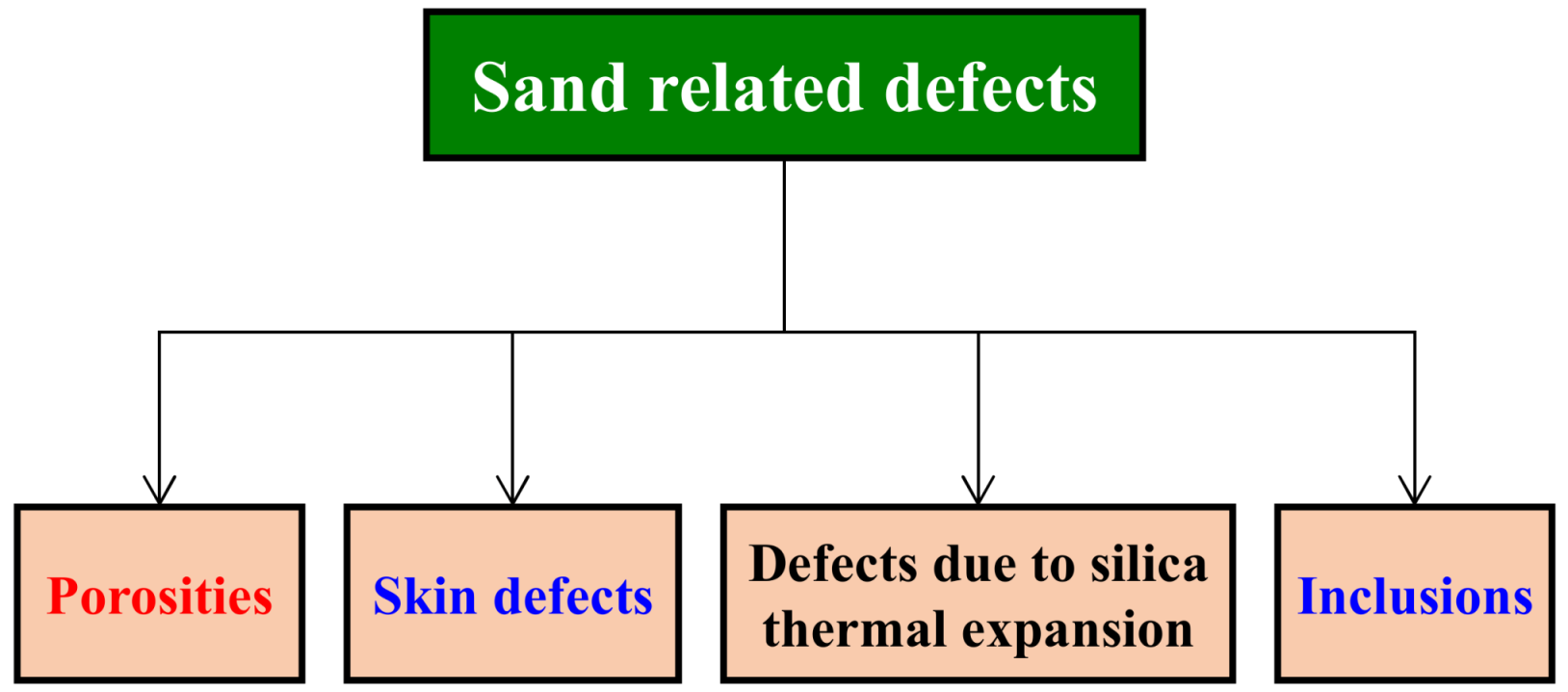
2. Sand-Related Defects
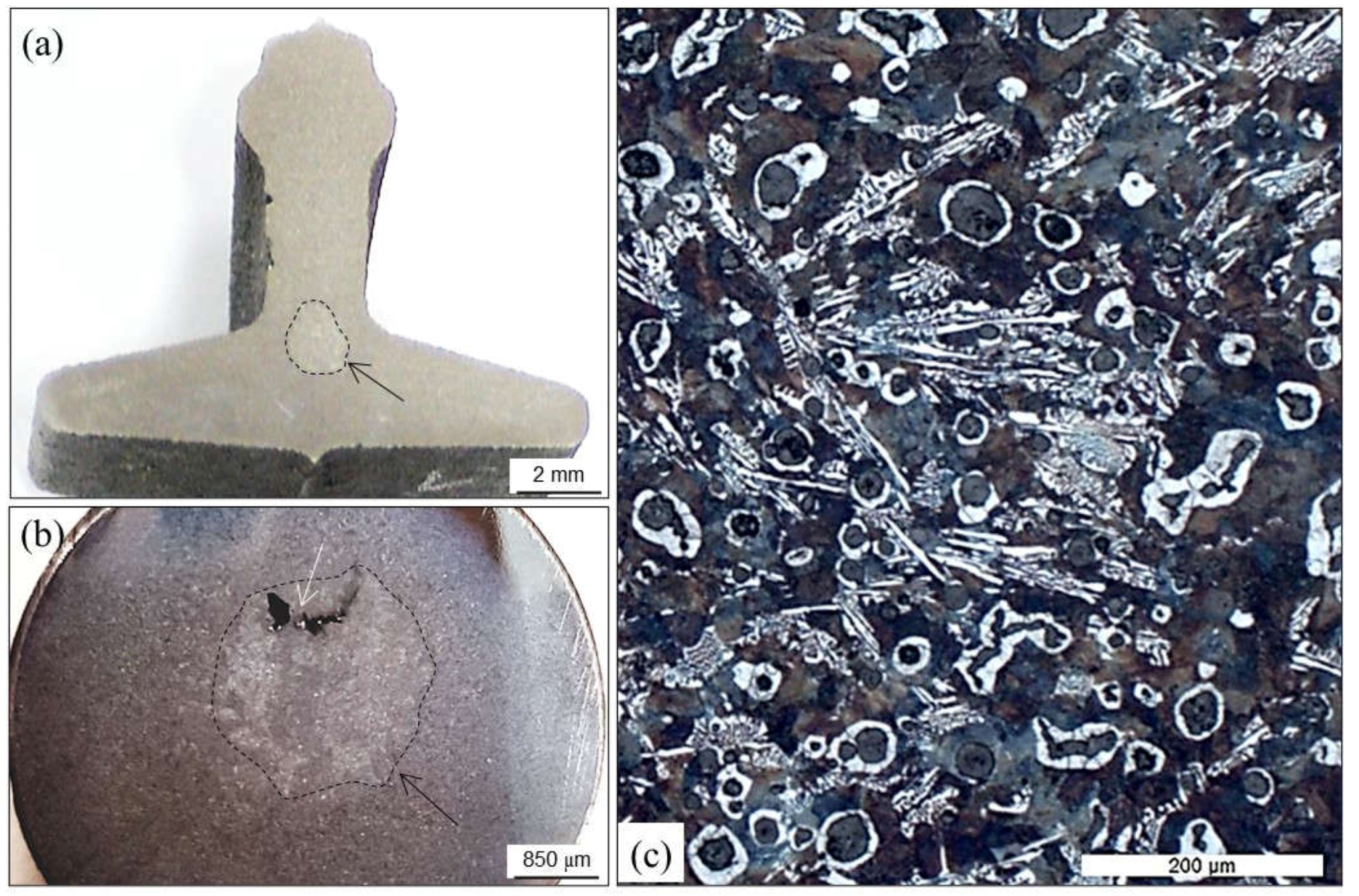
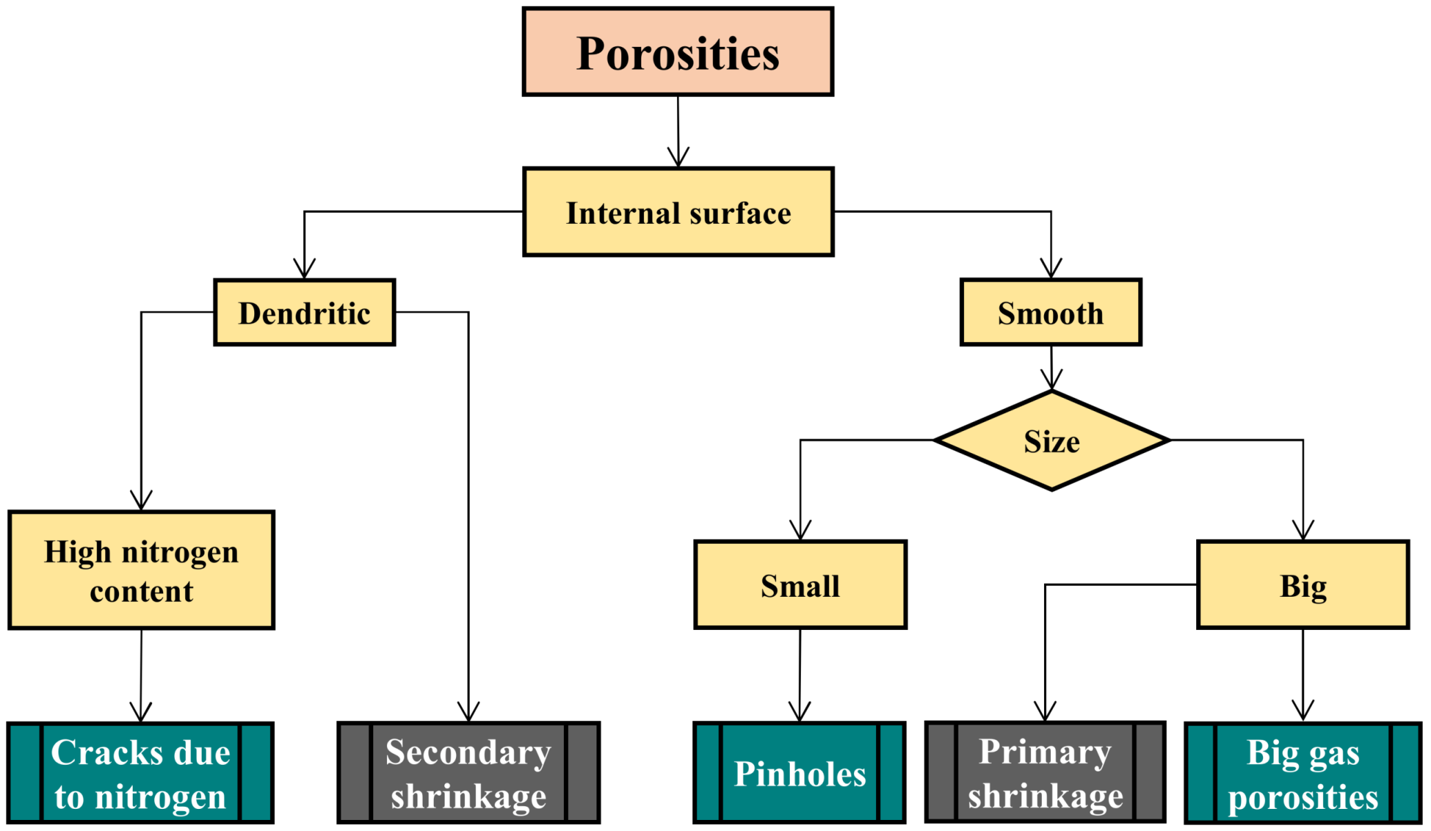
2.1. Porosities
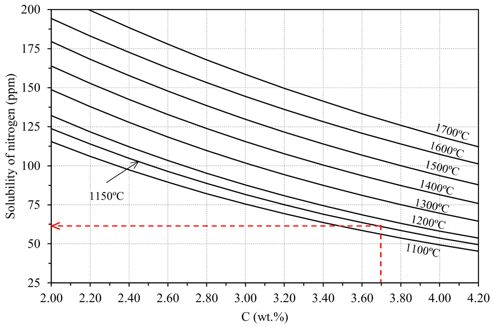
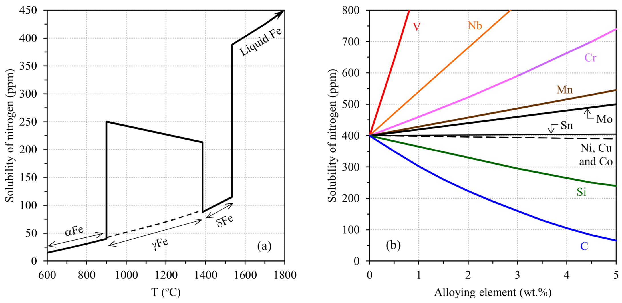
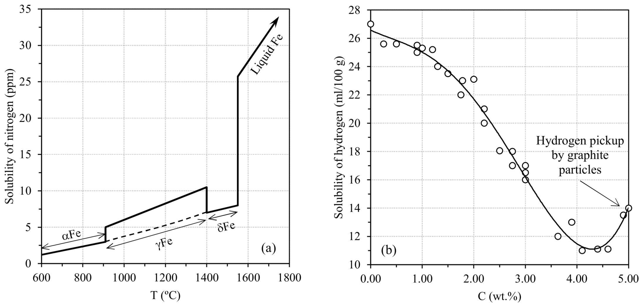
2.1.1. Gases in Cast Iron Melts

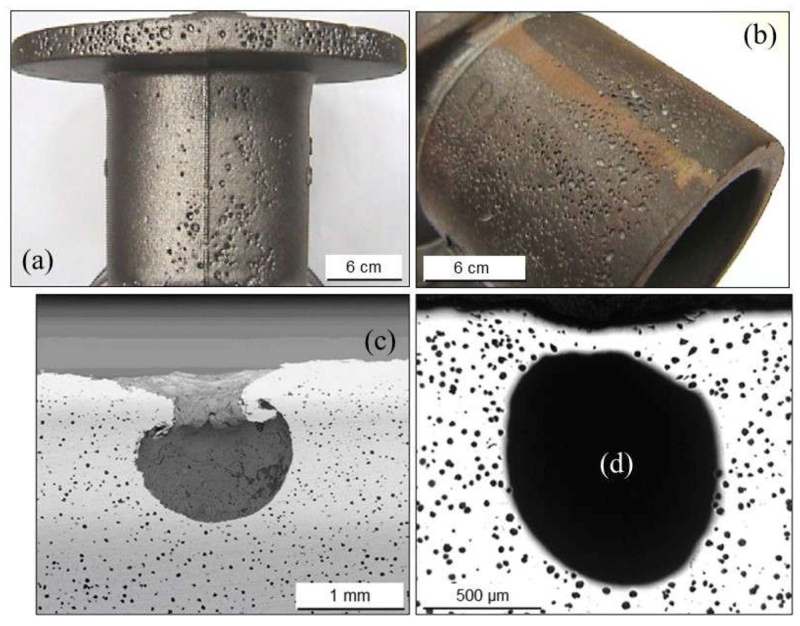
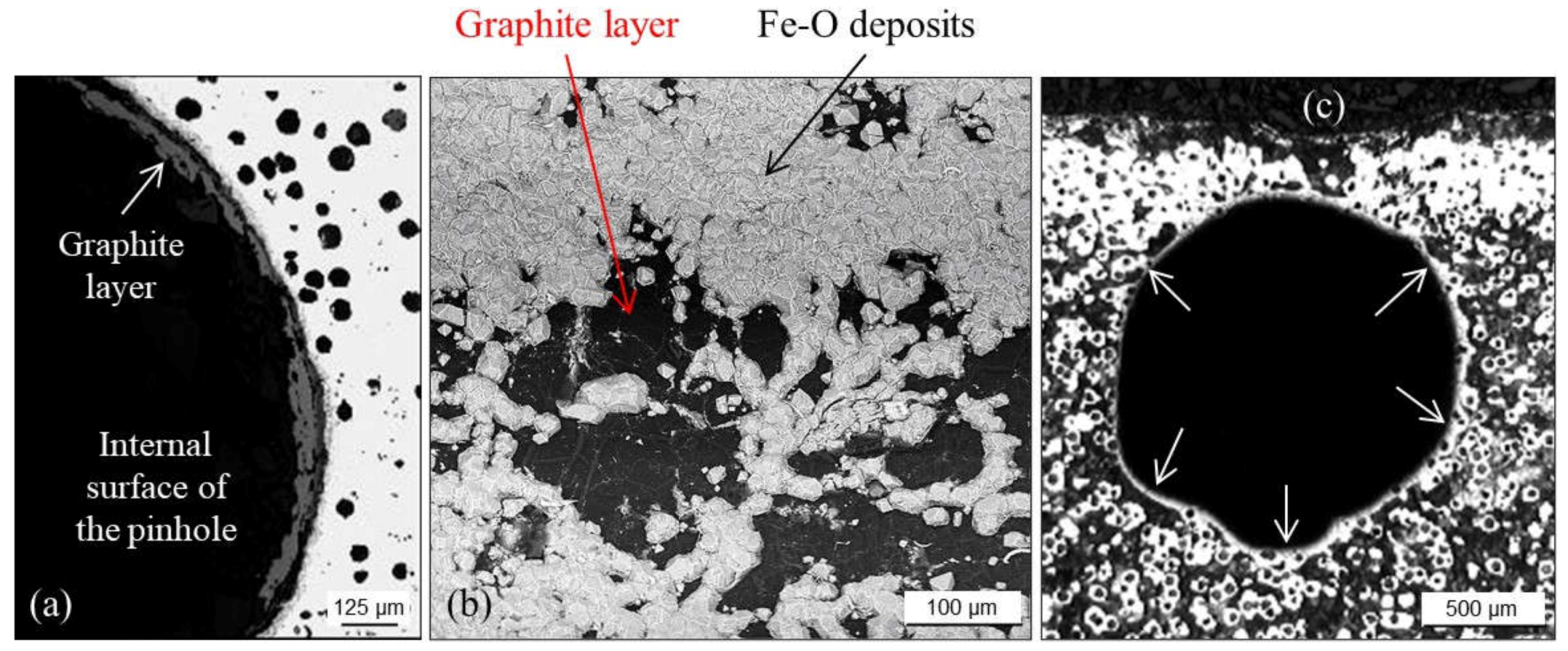
2.1.2. Pinholes: Small Gas Porosities

2.1.3. Blowholes: Big Gas Porosities
2.1.4. Cracks or Fissures Due to Nitrogen
2.1.5. Remedying against Gas Porosities
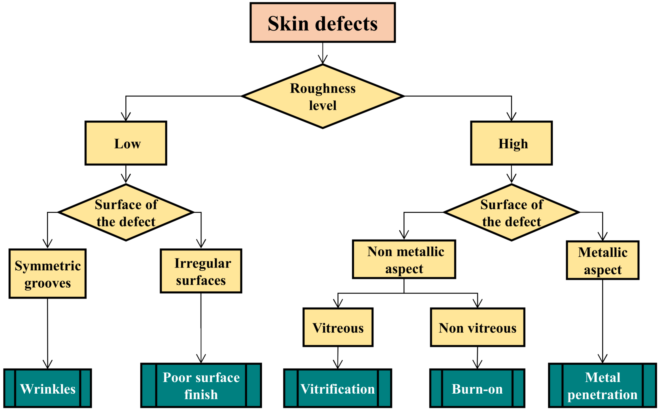
2.2. Skin Defects
- Minor defects such as wrinkles or high roughness are essentially aesthetic problems with no or little incidence on the casting soundness.
- Severe defects result from important thermal interactions between the cast melt and the compacted sand which forms the mold cavities (vitrification, burn-on and penetrations). These defects are associated with high roughness that can affect the coating quality and fatigue properties of finished parts.
2.2.1. Wrinkles
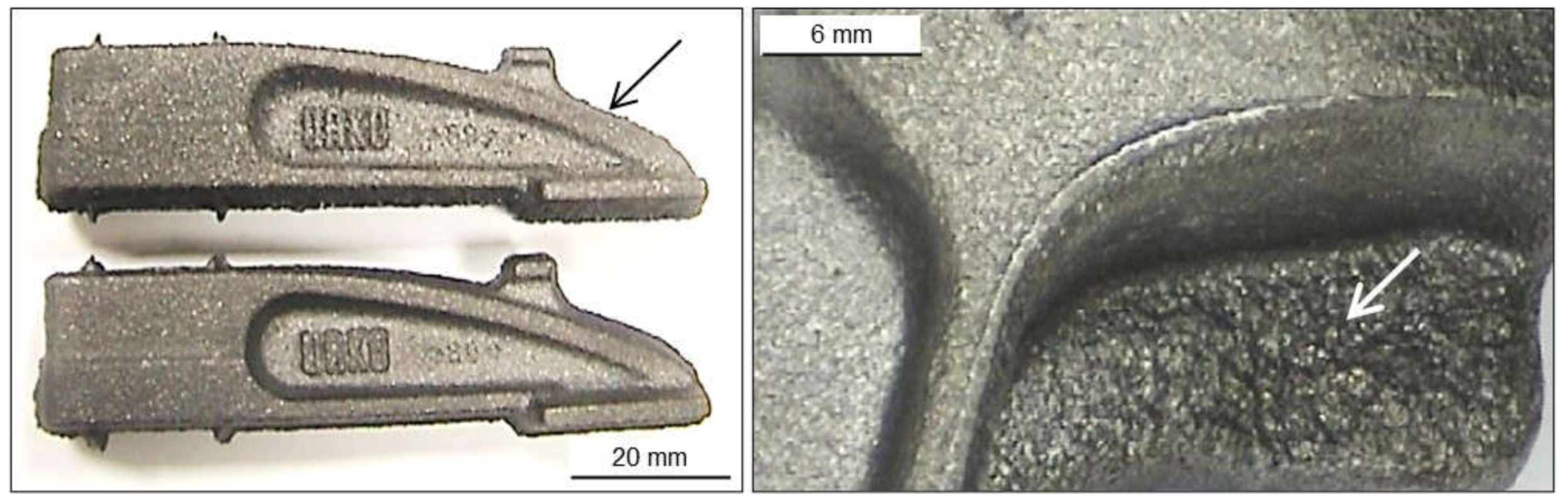
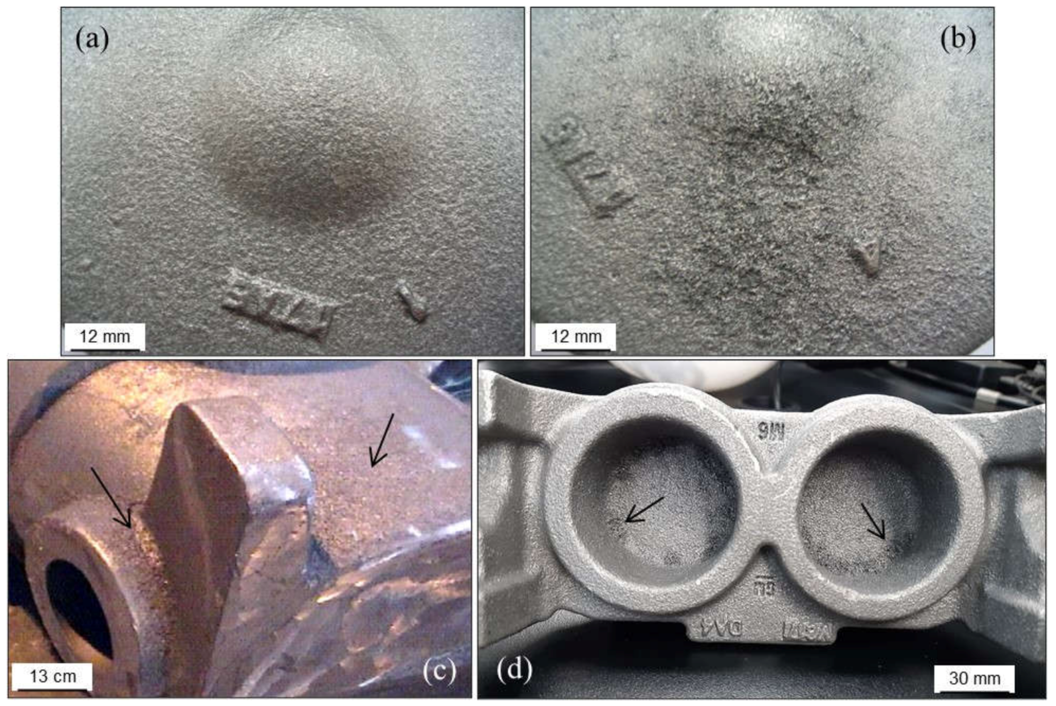
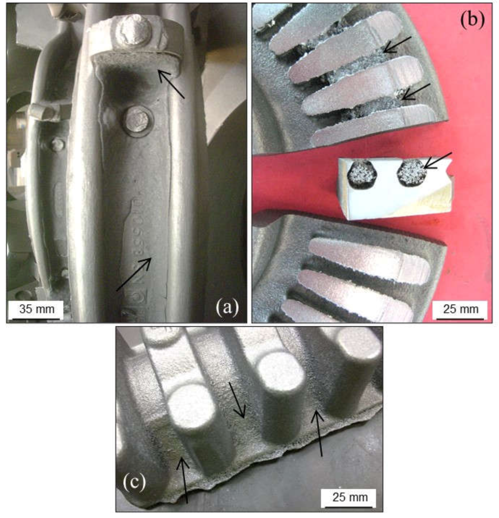
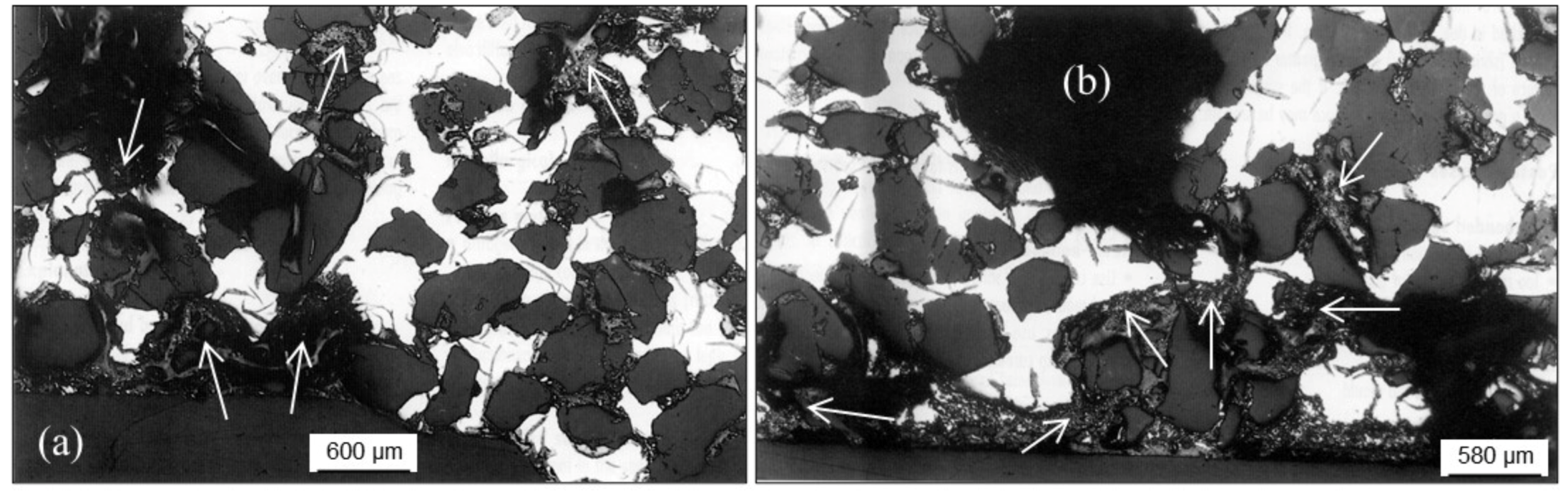
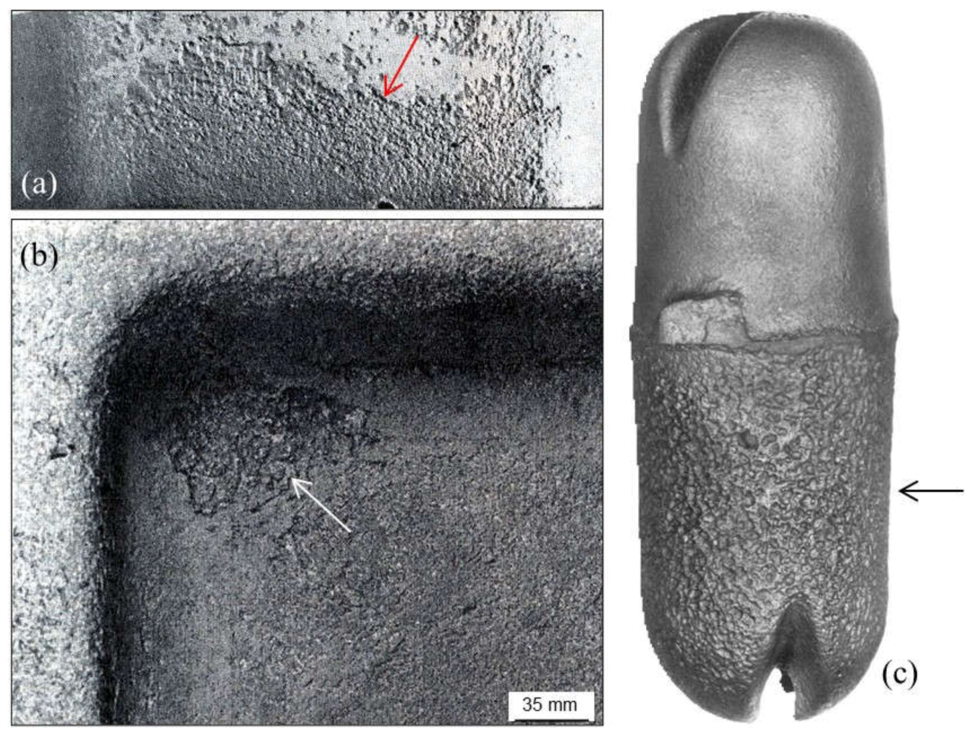
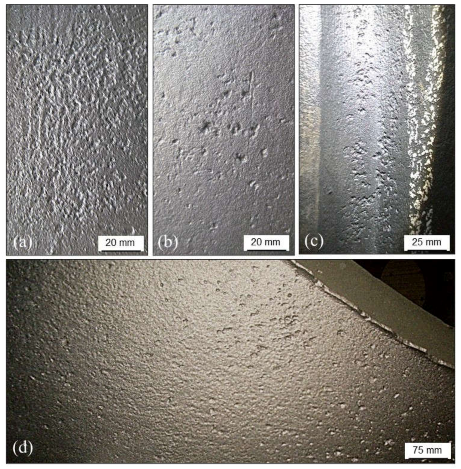
2.2.2. Poor Surface Finish
- The use of return or/and new sand grains with low AFS index (coarse grains).
- High compactability and permeability of the sand mixtures (low fluidity of the sand mixtures during molding process).
- Low loss on ignition value (low content of coal in the green sand mixtures). Keep this parameter in the range 4.0–6.0 wt.%.
- Low contents of silica sand grains in the green sand mixtures.
- Deficient mixing process (low mixing time or operative problems when mixing) which originate heterogeneous mixtures (comparative wet and dry fractions or even presence of “free” water in the mixtures).
- Low fines (particles size lower than 20 µm) content in the sand mixtures that leads to an increase in mold permeability.
- Inadequate (low) compaction of sand mixtures during molding step leading to molds with excessive permeability.
- Low strength of the prepared green sand mixtures (damaged molds).
- The use of inappropriate or damaged resins for core making.
- Excess of demolding liquids on the surfaces of molds (these liquids are used to ease the separation of molds from the patterns after squeezing step).
- Melt related and other common causes of poor surface finish are:
- High pouring temperatures (increase of melt fluidity and time before solidification) and low pouring times.
- The use of layouts with areas where metallostatic and/or dynamic pressure of the melt is high.
- Overheating of any part of the molds or cores (layout design).
- Inadequate coating of cores and/or molds.
- Lack of proper venting (problems when evacuating gases formed when filling the molds), which originates overpressures and promotes the interaction between the melt and compacted sand grains. Coated prints in cores, closed vents due to sand wash and/or other tools on.
- Phosphorous content lower than 0.050 wt.% in grey cast irons increases the risk of metal penetration in castings.
2.2.3. Burned-In Sand: Calcination
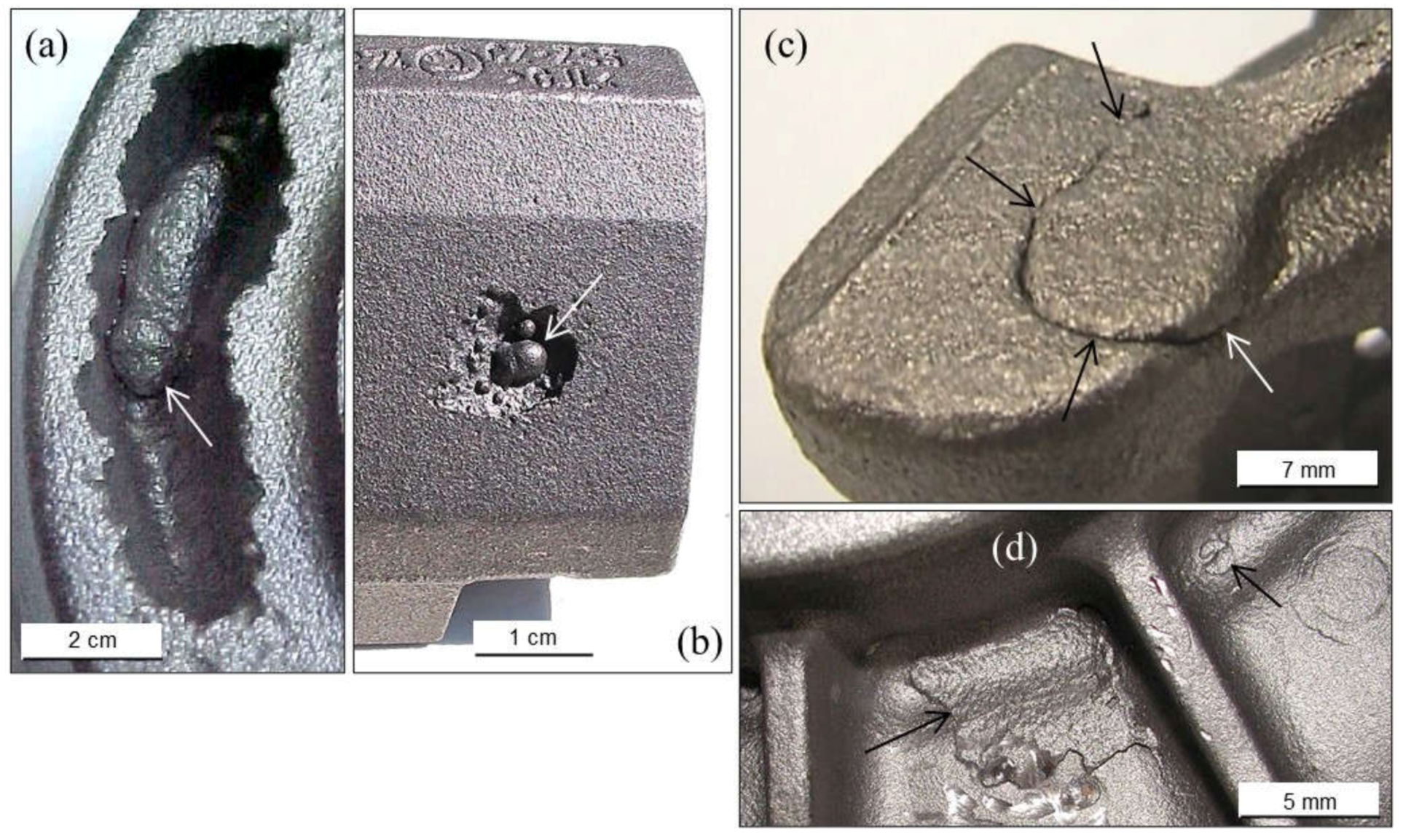
2.2.4. Metal Penetration
Metal Penetration without Chemical Reaction
Metal Penetration with Chemical Reaction
Explosive Penetration
2.2.5. Vitrification
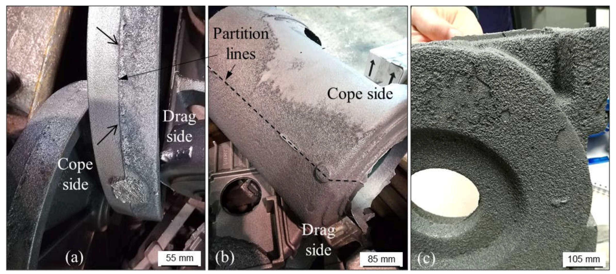
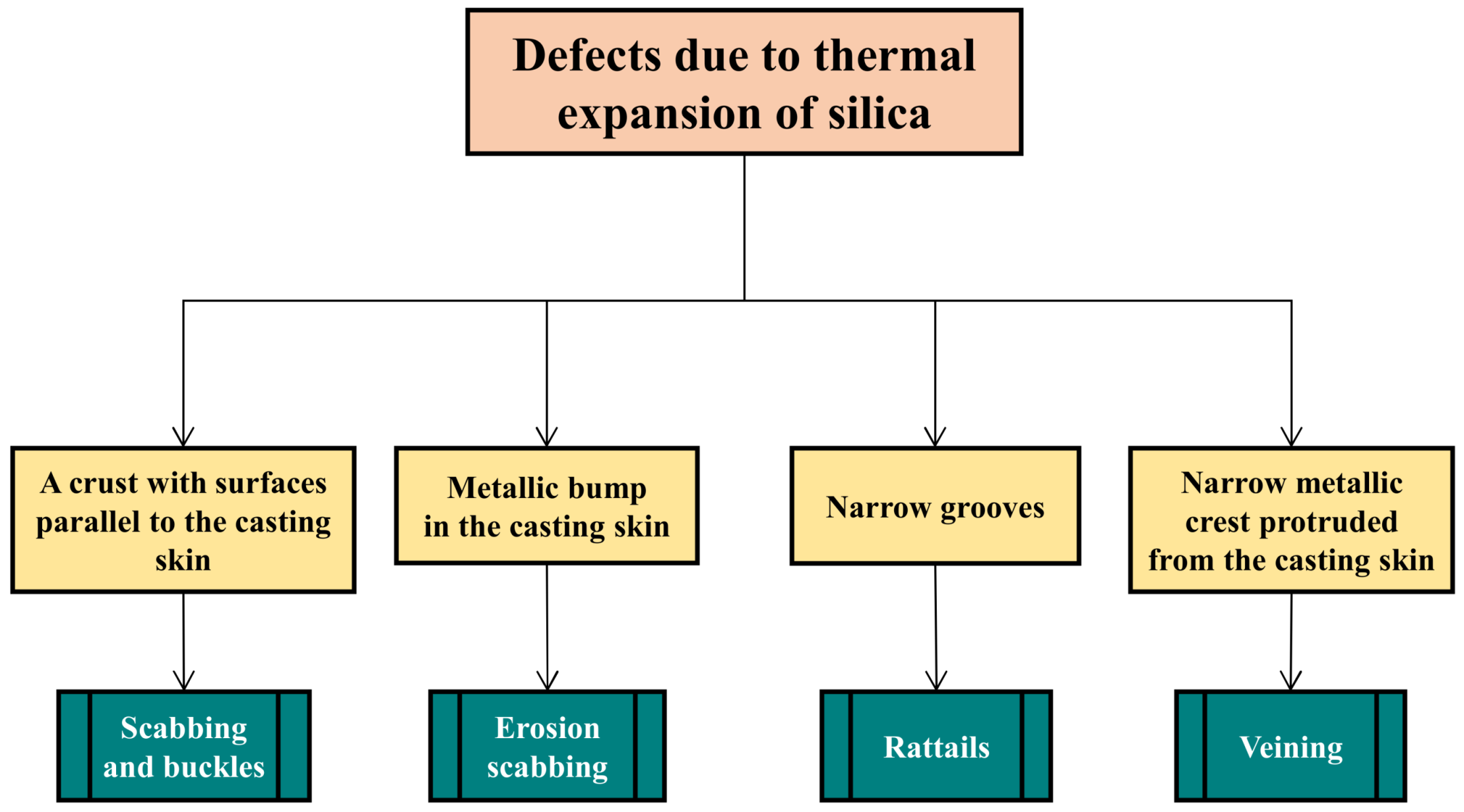
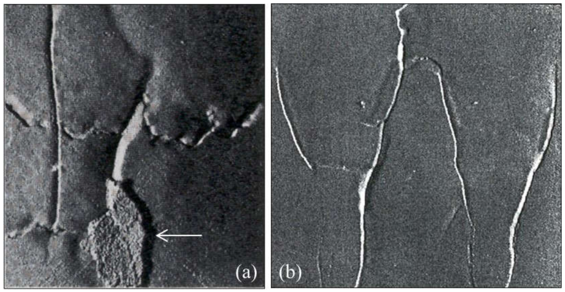
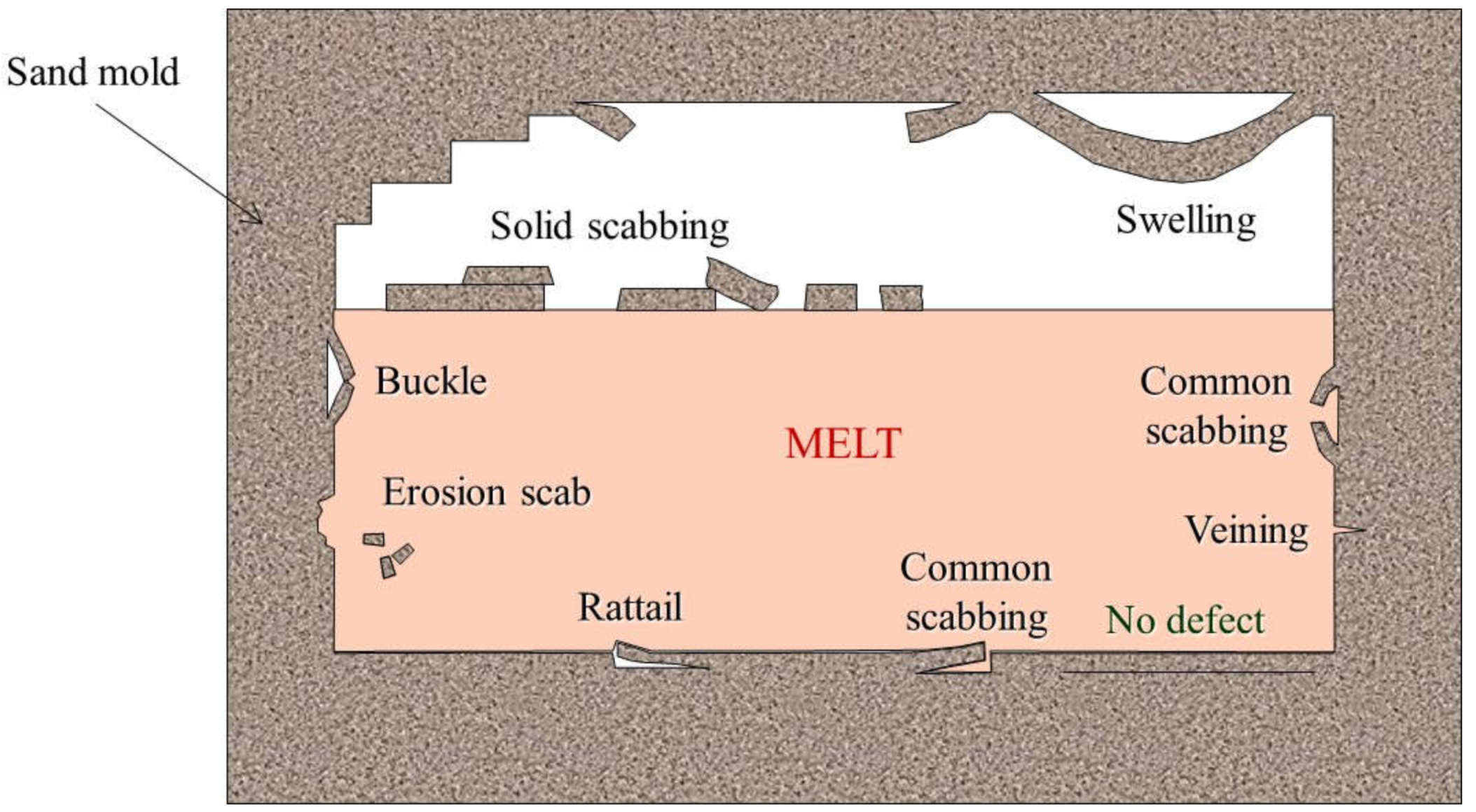
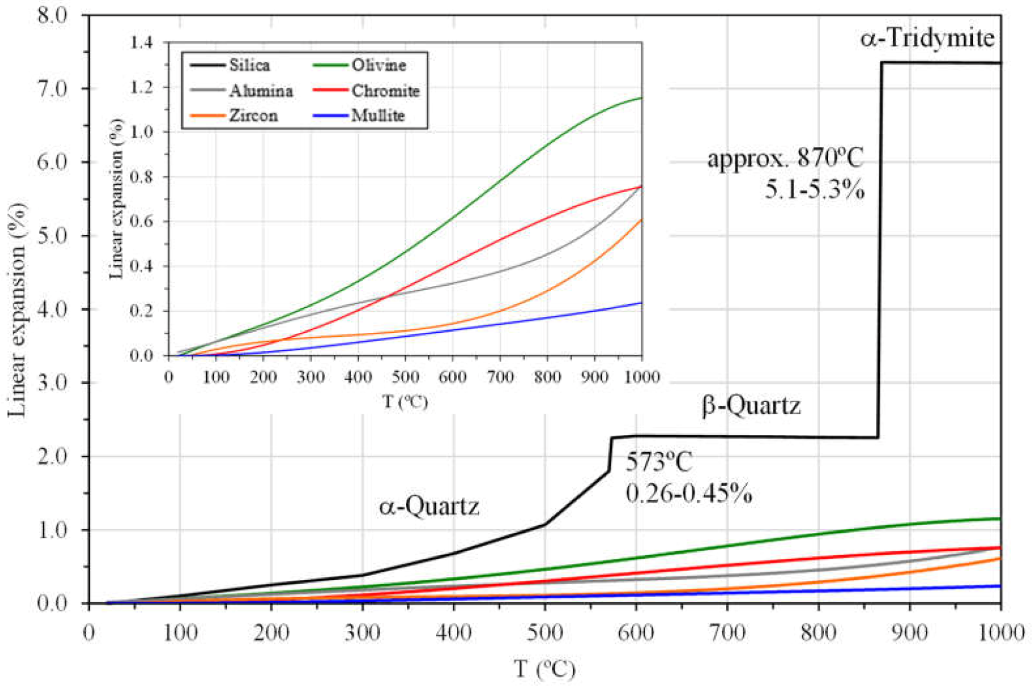
2.3. Defects Due to Silica Thermal Expansion

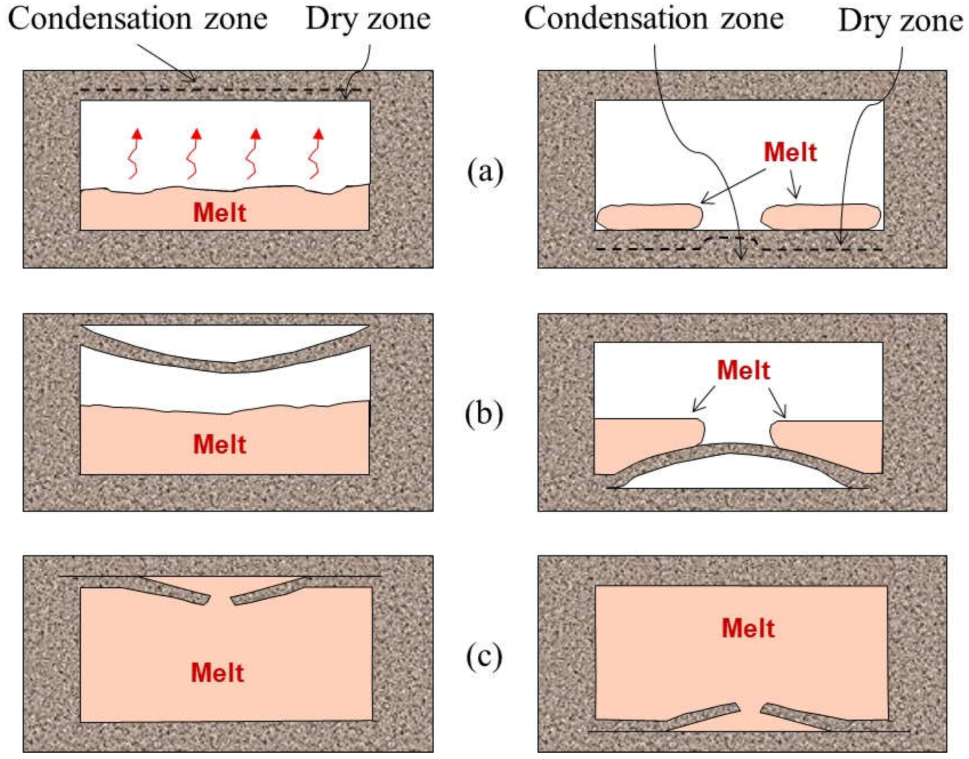
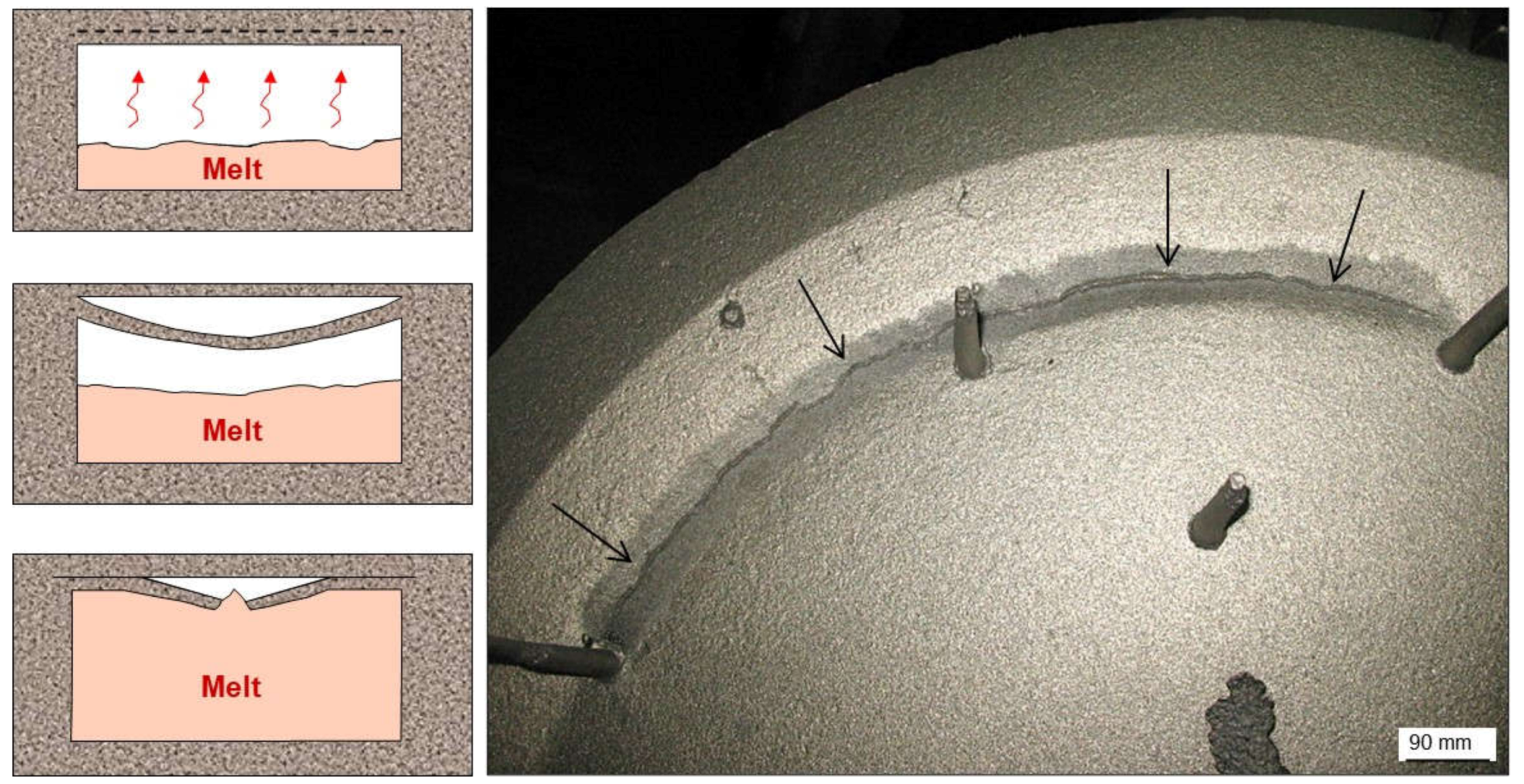
2.3.1. Scabs and Buckles
2.3.2. Erosion Scabs
2.3.3. Rattail
2.3.4. Solid Scabs
2.3.5. Veining
2.3.6. Remedying Defects Due to Silica Expansion
- Effective control of silica grain sizes avoiding coarse and rounded ones.
- Use of sand distributions in which a minimum of three sieves must contain more than 10 wt.% of the total weight in a tested sand sample (compensated grain distributions to minimize cooperative expansion effects).
- Keep satisfactory contents of bentonite, coal (high enough loss on ignition values) and fines in the green sand mixtures to cover all grains with enough coating and to compensate for expansion efforts.
- Keep adequate strength values in the green sand with proper bentonite and water contents.
- Avoid the use of low-quality bentonites, contaminated water and/or ineffective mixing processes.
- Minimize pouring temperatures to limit possible overheating effects in any area of the cavities.
- In case of coated molds or cores, assure a proper adsorption of the product to guarantee that sand grains are correctly surrounded and also protected against intense radiation.
- The tendency of a given green sand mixture to scabbing is evaluated with the parameter “wet tensile strength” that should be kept higher than 0.20–0.25 N/cm2.
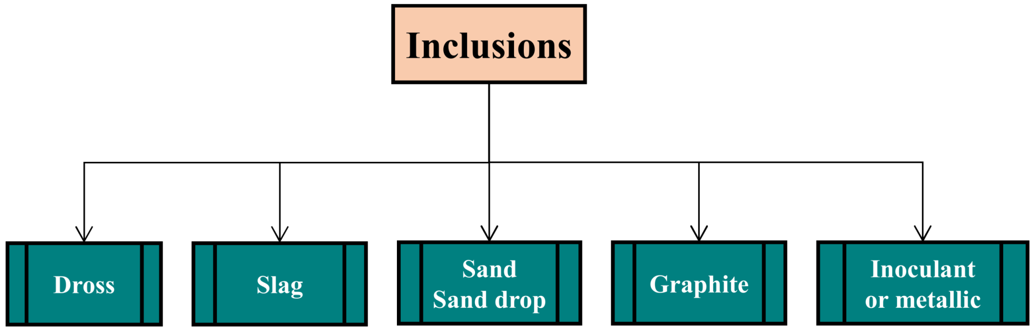
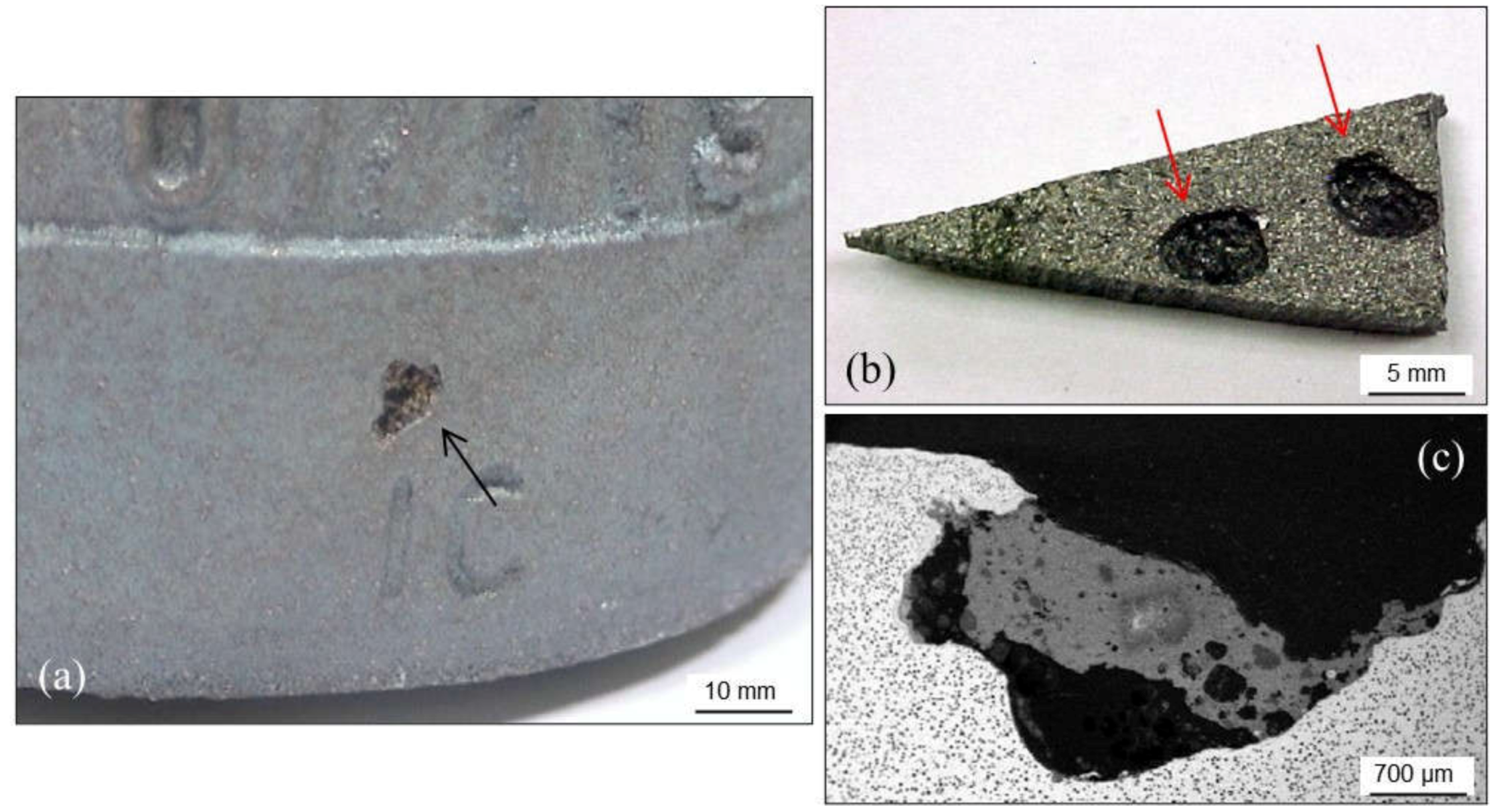
2.4. Inclusions
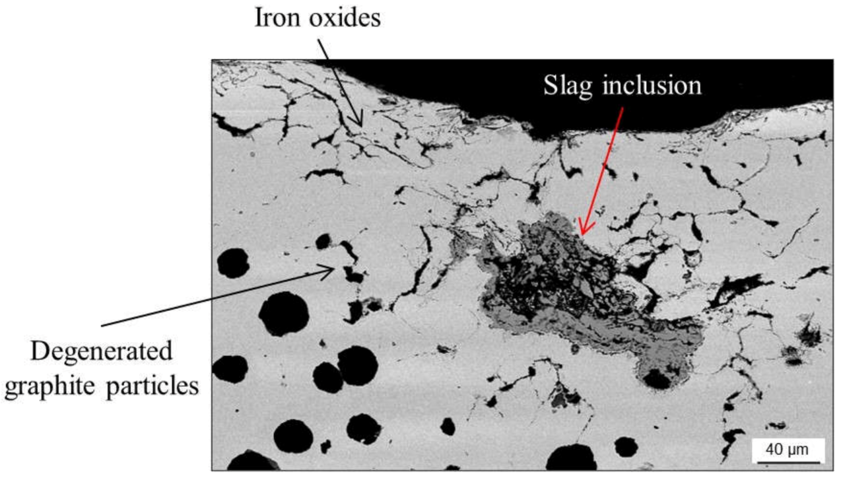
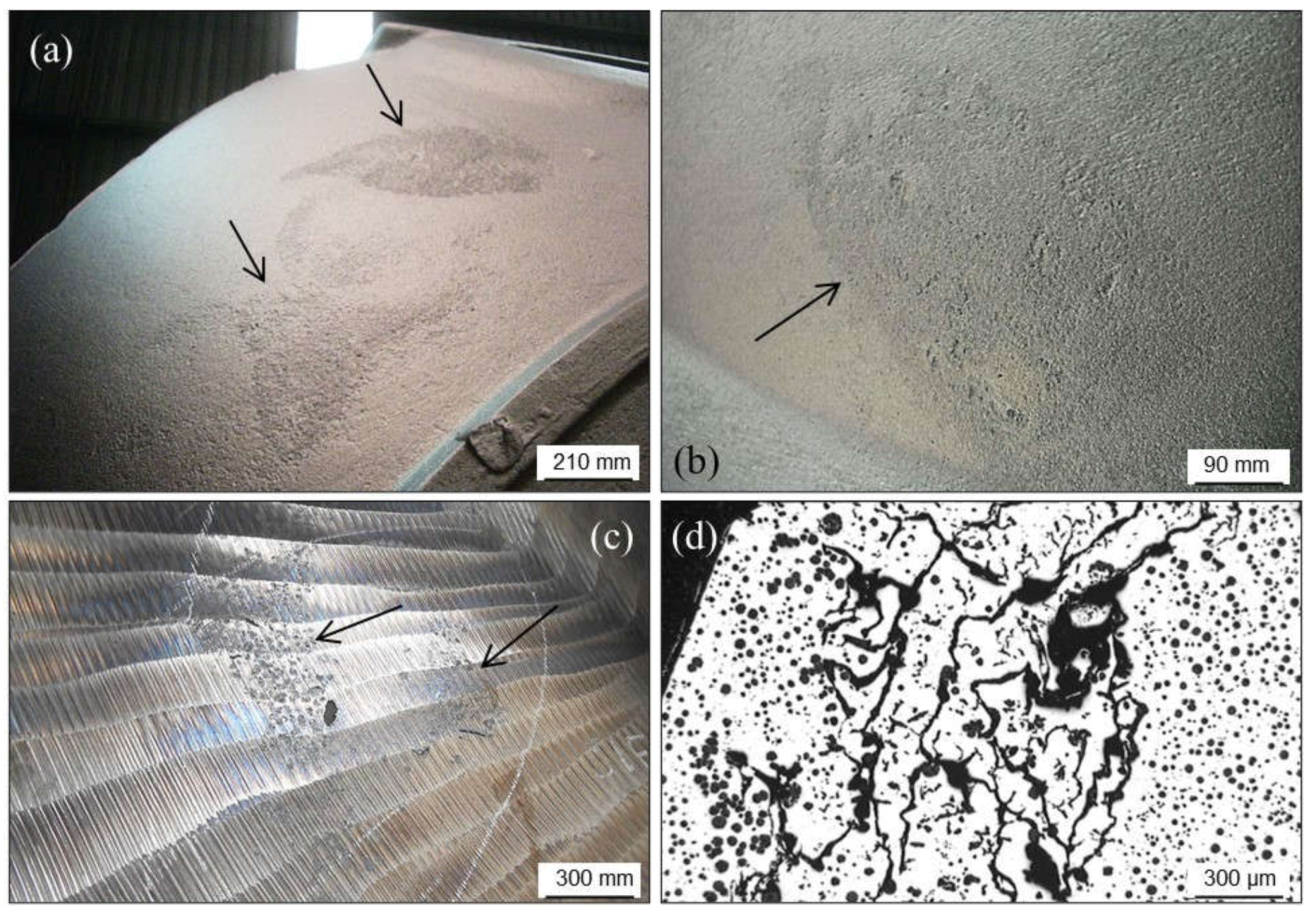
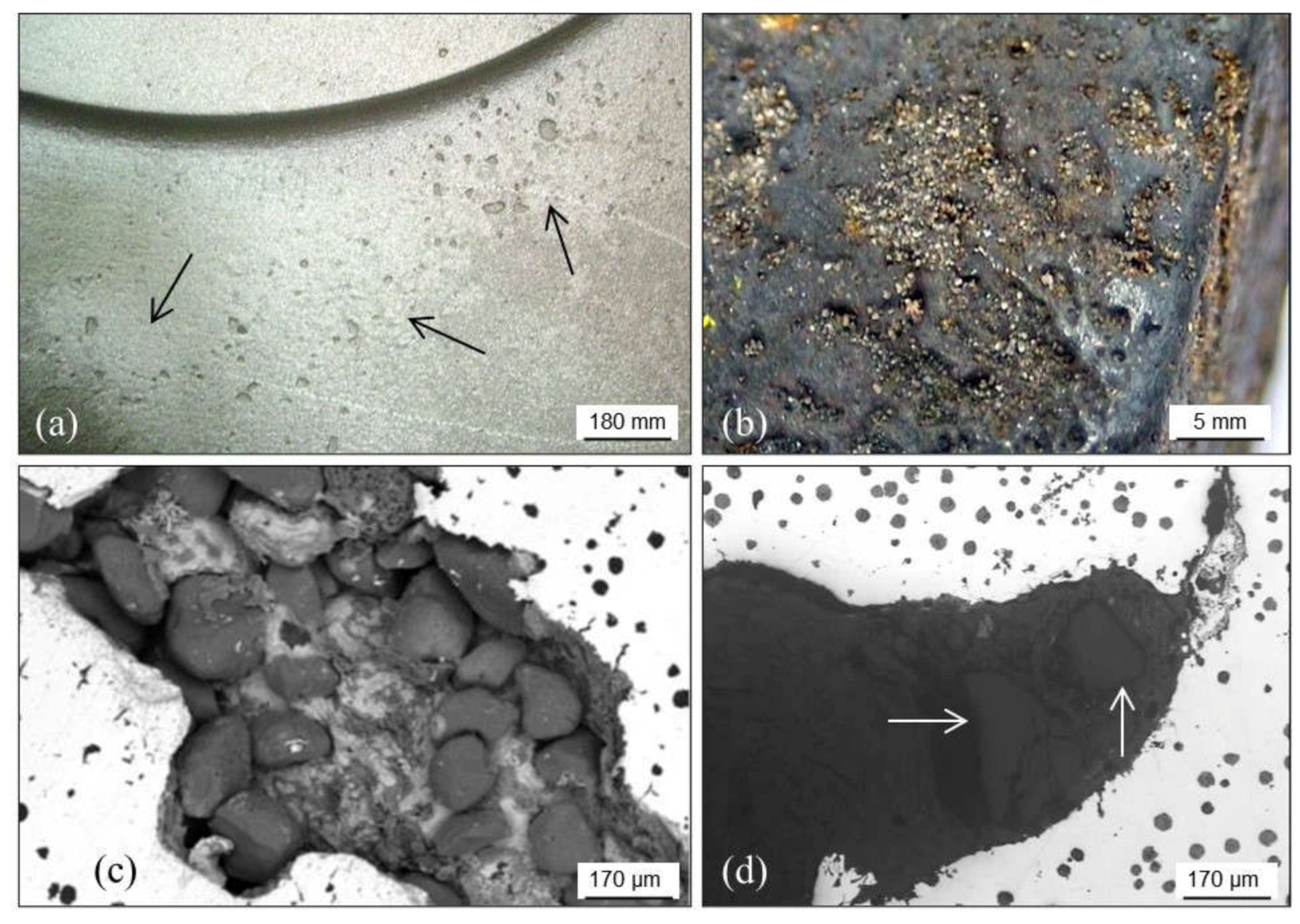
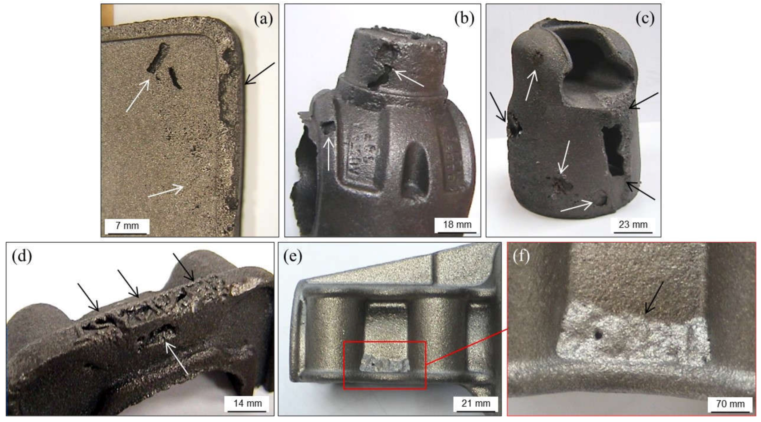
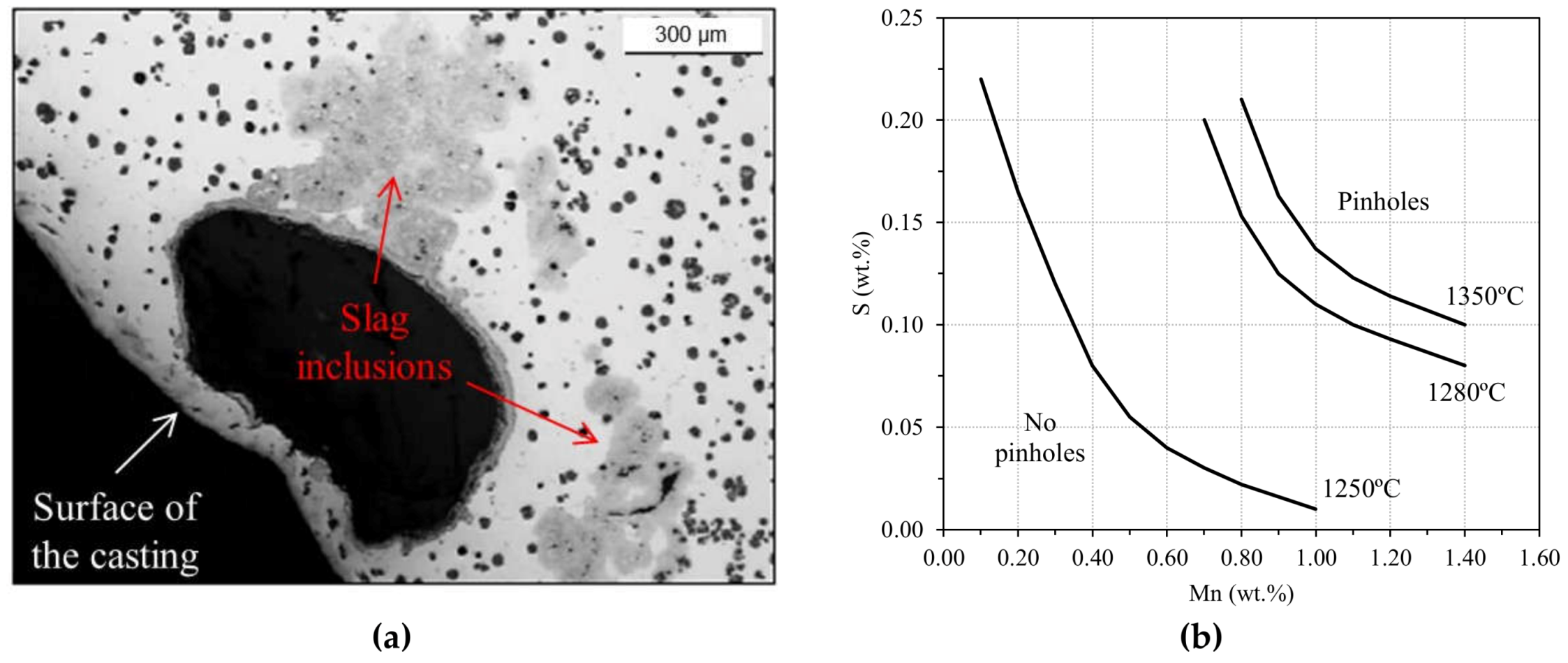
2.4.1. Slag Inclusions
- Reduce the amount of oxides present in the metallic charges used for preparing base melts.
- Increase the pouring temperature (slag inclusions can be easily trapped in the alloy when increasing cooling rate). Temperature-controlled pouring systems show lower risk than manual pouring ladles. Note that it is the pouring temperature of the last molds that you should pay attention to.
- Avoid long time periods between melt preparation and the pouring step.
- Keep proper S vs. Mn ratio in the melts. For grey irons, the optimal ratio is given by Mn (wt.%) = 1.7·S (wt.%) + 0.2.
- Assure satisfactory deslagging of melt batches before pouring.
- Use refractory materials in casting tools with low reactivity at high temperature.
- Pouring practice must guarantee that cup and down sprue are totally full and that the filling is not interrupted.
- Slag inclusions formed into molds are quite related to turbulence. Check if improvements could be made to the layout to smooth filling, that the section changes in runners and ingates are appropriate, if filters or slag trapping shapes can be added, etc.
- Avoid contaminations and excessive contents of not refractory constituents in the green sand mixtures. This means that a proper regeneration level is needed, adding new silica sand.
- Assure a correct compaction of sand grains during molding processes for minimizing interactions with the melts.
- Keep high enough loss on ignition values in the green sand mixtures (reduction of reactive oxygen level in molds).
2.4.2. Dross
2.4.3. Sand Inclusions (Sand Drops, Sand Cuts and Sand Washes)
- The use of green sand mixtures with low moisture or compactability. Water makes bentonite play its necessary role of bonding the sand grains so as to maintain effective compaction. Low water content, thus, originates high erosion risk in molds both before pouring and when filling the molds (friability).
- Poor mixing, which leads to irregular absorption of water by bentonite and other constituents of the mixtures, leading to fractions with low humidity and high friability.
- Low bentonite content in the sand mixtures (bentonite originates strength in the compacted molds).
- The use of sand mixtures with high contents of coarse grains (low AFS index values) and of silica grains (highly regenerated mixtures).
- High carbon content, capable of absorbing most of the water intended for mixing with bentonite.
- Poor compaction of sand mixtures during the molding step (free grains or groups of grains).
- Pouring molds produced long time ago (drying effect is always present).
- Turbulent and/or aggressive filling of molds which increase the risk of erosion.
- Damages produced on any part of molds and cores as a result of bad practice during molding step (not correct closing of drag and cope, inefficient core prints which allow some core shaking and erosion in the touching areas, molds and cores damaged during handling or being transported, etc.).
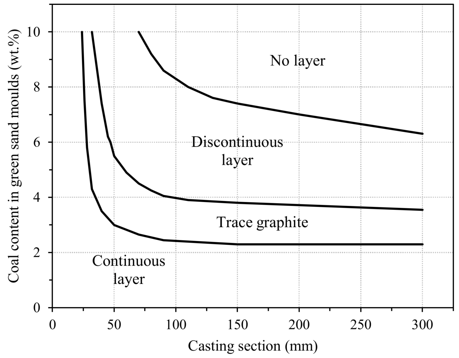
2.4.4. Lustrous Carbon Inclusions
- The use of low pouring temperatures and high pouring times and/or of long runners, which promotes relevant temperature losses in melts.
- If blue shades are detected close to the defect, the most probable cause is the high content of coal in the green sand mixtures used to produce the molds.
- Organic resins used for hardening cores are also burned when pouring the molds, increasing the lustrous carbon deposited.
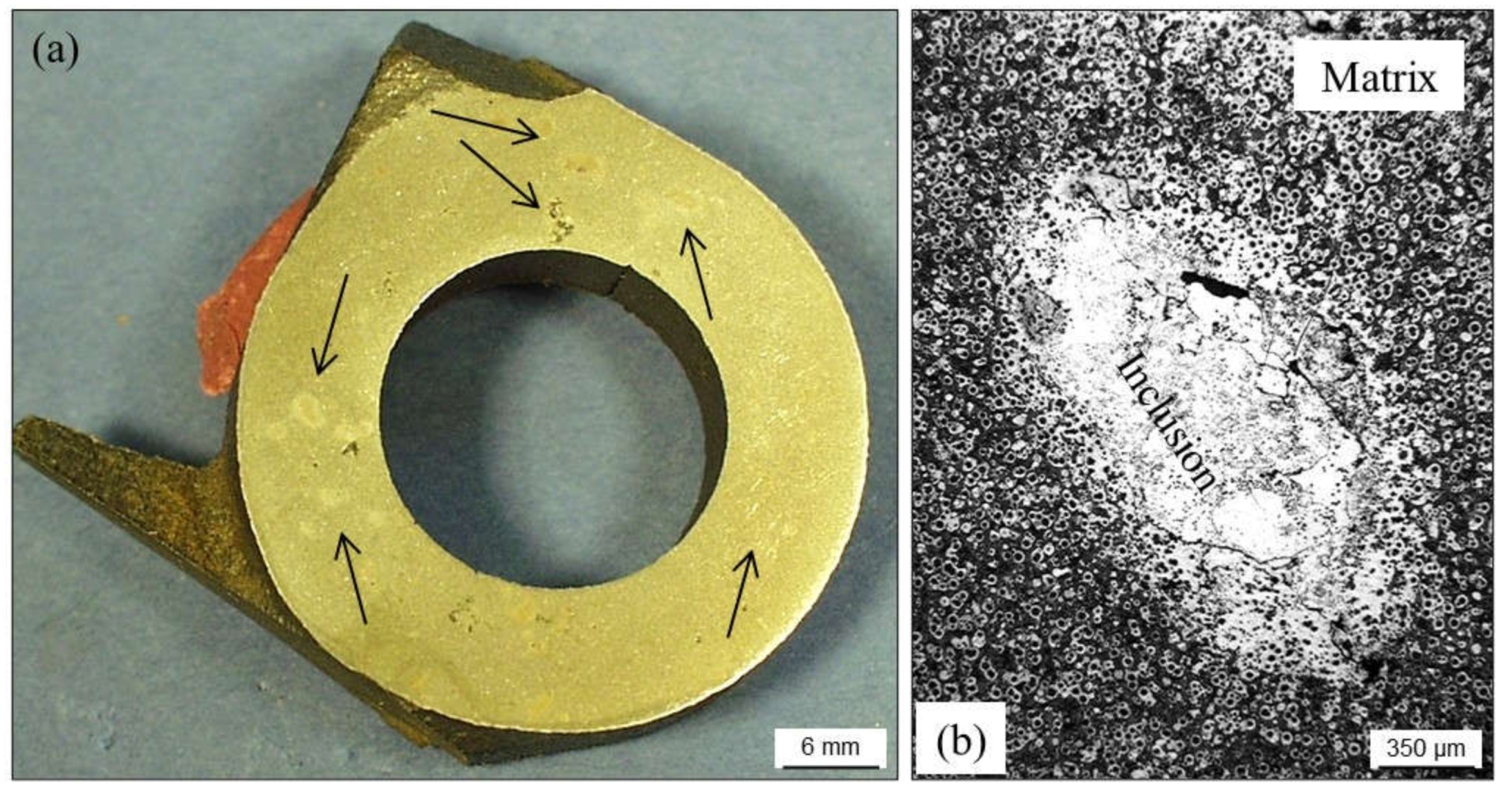
2.4.5. Inoculant and Metallic Inclusions
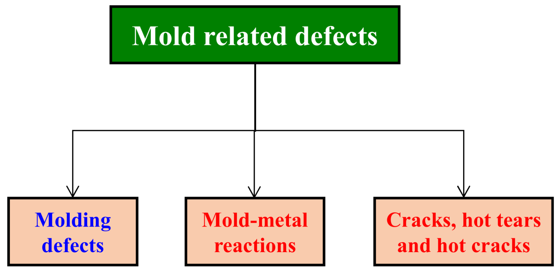
3. Mold-Related Defects
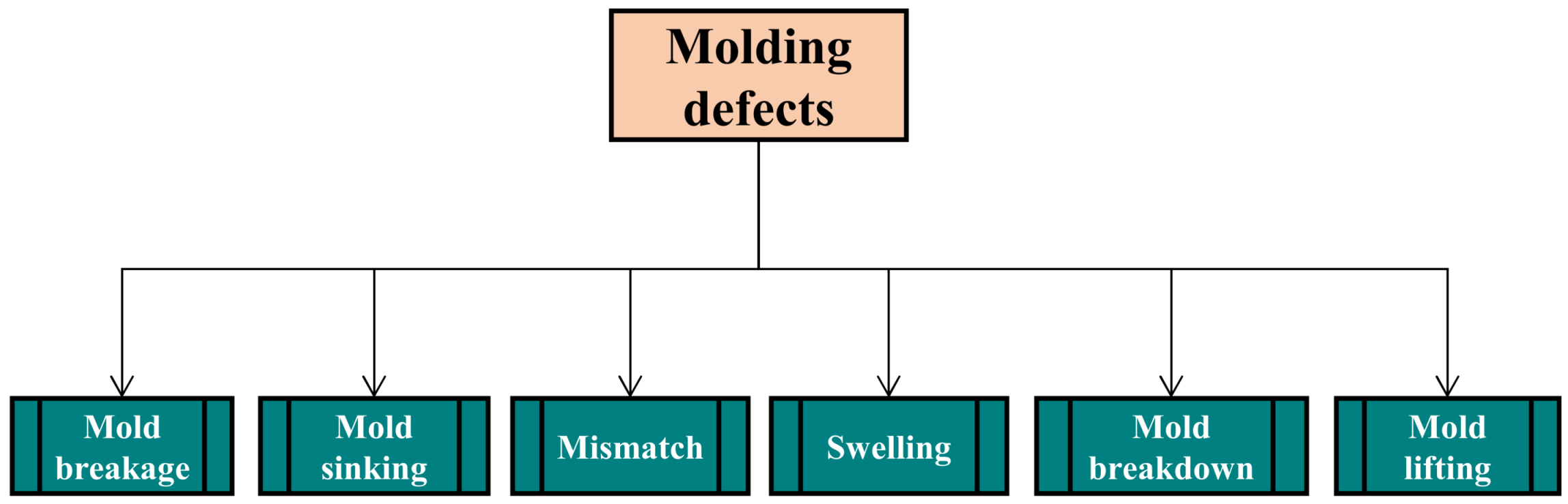
3.1. Molding Defects
3.1.1. Mold Breakage
- Too high moisture and/or compactability of green sand mixtures, often leading to low strength and high deformability of the molds.
- Too low moisture and/or compactability of green sand mixtures, which makes the compacted sand dry-rigid and friable with high risk of mold cracking. This can be related to the use of hot sand mixtures that get quickly dry and friable.
- Low homogeneity of sand mixtures due to low mixing time, malfunction of mixers, irregular additions of essential constituents, etc.
- Low temperature of pattern plates, which originates local condensation of water in those areas of sand mixtures in contact with the model. These areas remain stuck to the model when separating drag or cope from the patterns. Good venting of pattern plates and an effective control of separation speed can prevent this problem.
- Insufficient demolding angles in models that make difficult separations of drags and copes from pattern plates.
- Low or irregular compaction of molds due to errors in the molding facilities, lack of demolding liquid, use of pattern plates without previous warming, wrong molding practices, etc.
- Closing molds carelessly and with impacts between drags and copes.
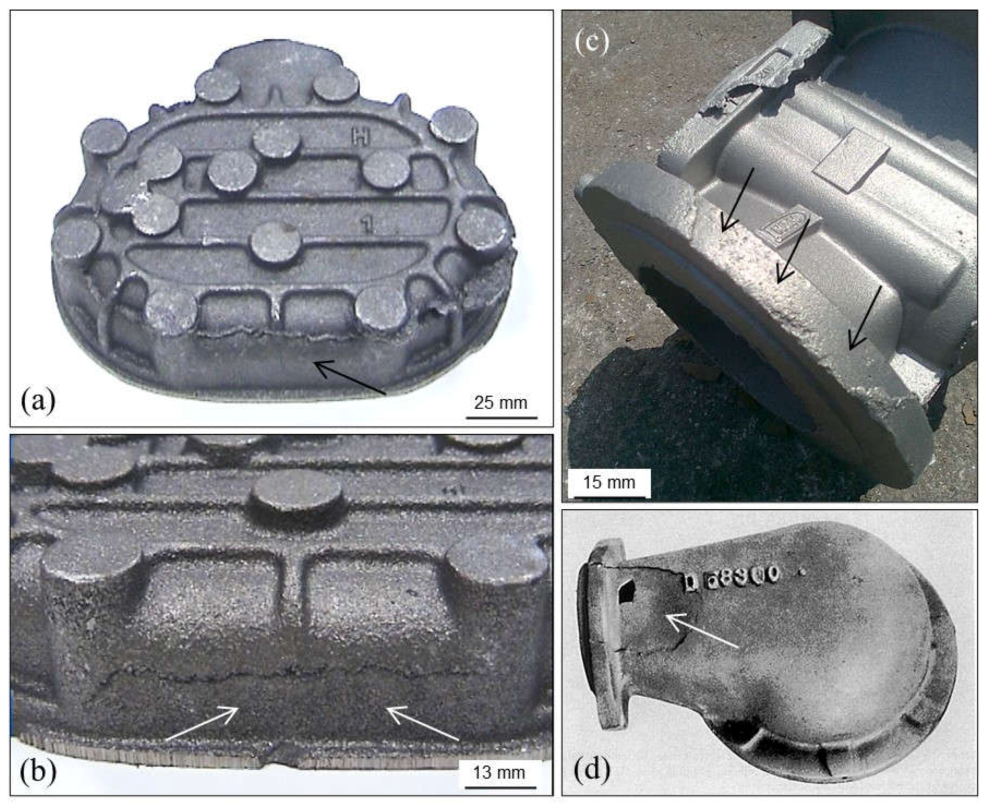
3.1.2. Mold Sinking
3.1.3. Mold Failure or Collapse
3.1.4. Swelling
3.1.5. Mismatch
- Any external action which provokes deviations of matching between drags and copes.
- In horizontal molding lines, too much clearance of the lugs and pins, which does not guarantee a correct match of drags and copes.
- Malfunction of molding operations and/or of molds transport systems in automatic vertical molding lines.
- Too high dynamic and metallostatic pressure in the molds, which can push cores out from their correct locations.
- Too high dimensional tolerance of core prints.
- Inadequate locking of horizontal partitioned molds (low and/or unbalanced clamping of closed molds). Incorrect location of counterweights on molds.
3.1.6. Mold Lifting or Mold Separation
- The use of copes with large heights with respect to drags heights, leading to high pressure on the areas close to the partition line.
- Insufficient counterweighting on horizontal molds or inefficient clamping.
- Accumulation of gas into molds (lack of venting), which can separate the two half-molds.
- Long distances between pouring cups and nozzles (long melt streams which originate high dynamic pressure of melts) and long down sprues can also lead to this effect.
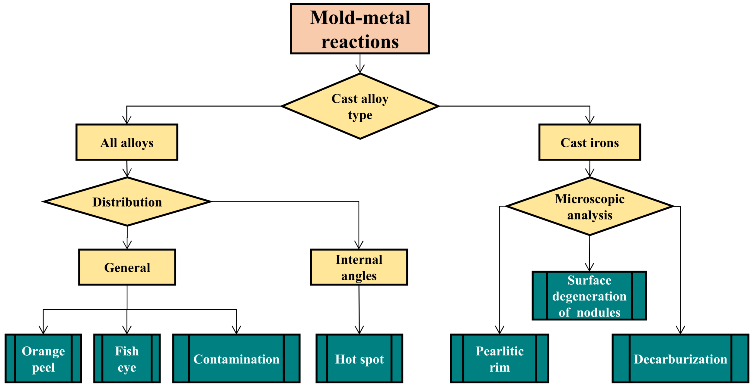
3.2. Mold–Metal Reactions
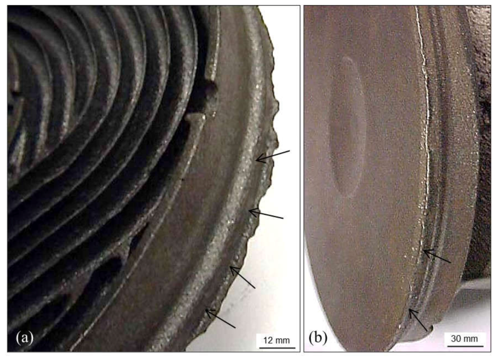
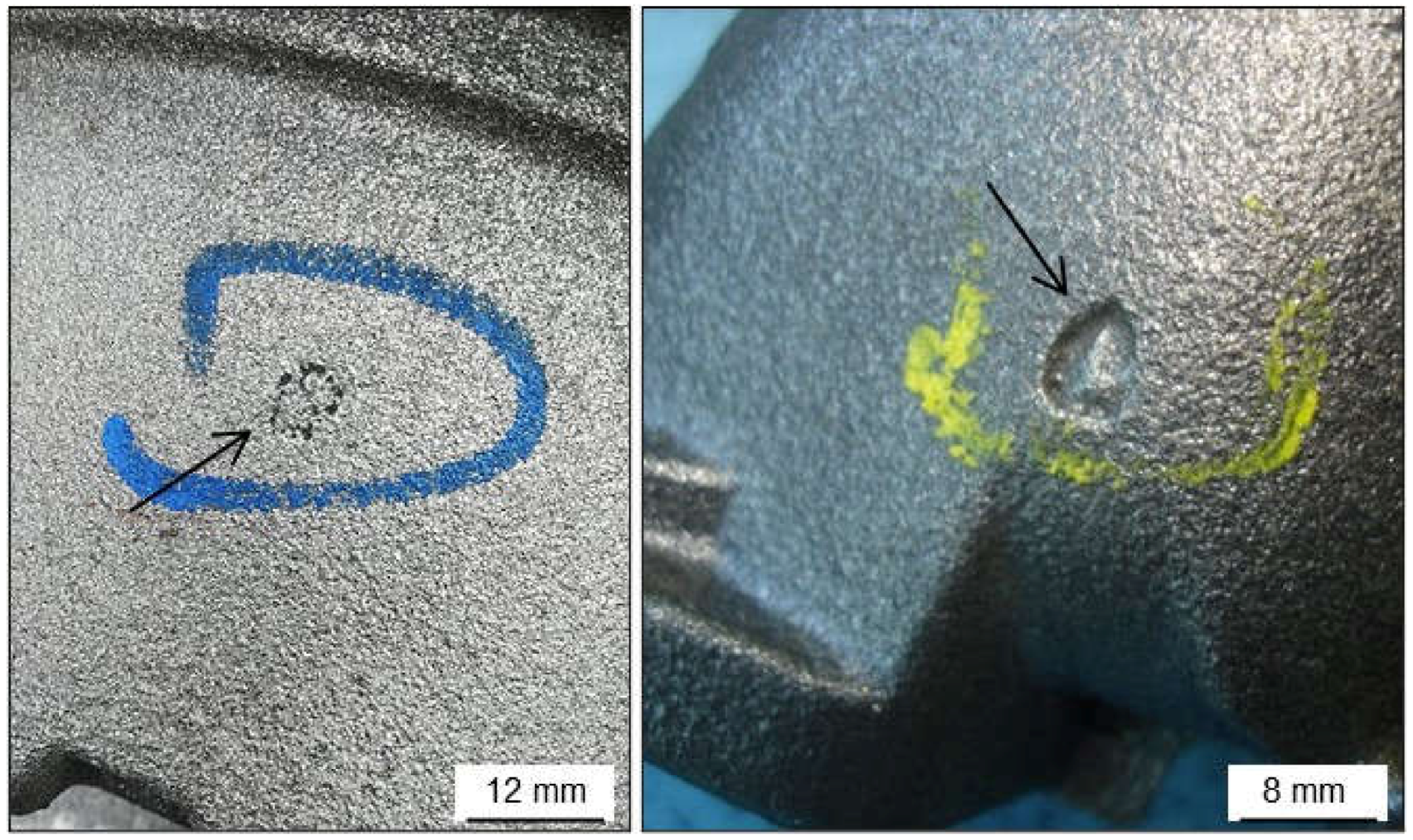
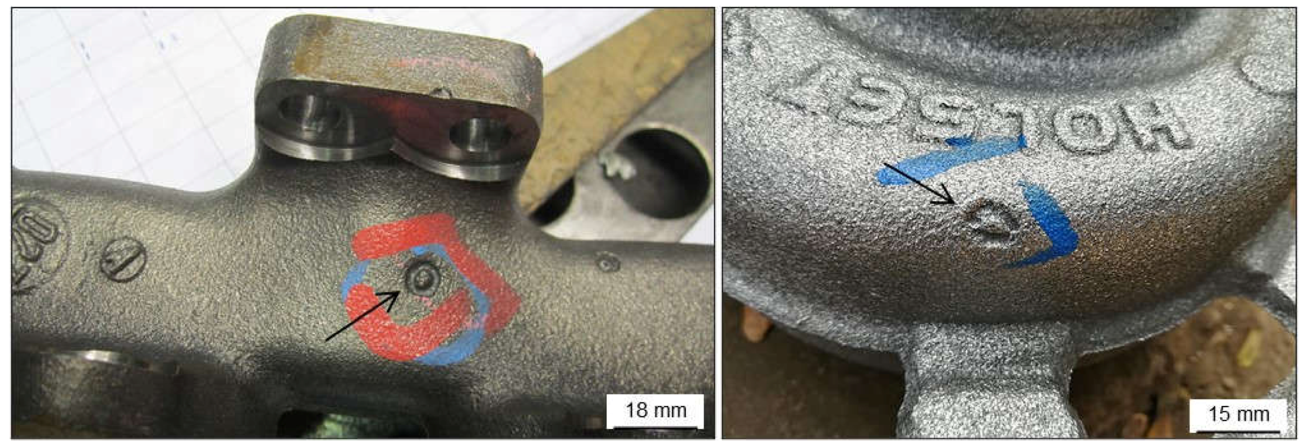
3.2.1. Pitting or “Orange Peel”
- High silicon, magnesium and aluminum contents in the cast alloys.
- High or even intermediate contents of any compound with low refractory in chemically bonded sand mixtures used for mold making (resins, ashes, additives, catalysts, etc.).
- Low pouring temperatures (slag formation is promoted and these compounds promote reactions between melts and sand molds).
- High pouring temperatures which promote oxidations in the mold–metal interface.
- Low quality of silica sands (low refractoriness).
- Low additions of new sand to prepare green sand mixtures.
- Low loss on ignition values in green sand mixtures.
- The use of complex layouts with high number of hot spots in castings.
- Insufficient protective coating or low quality of the coating products used.
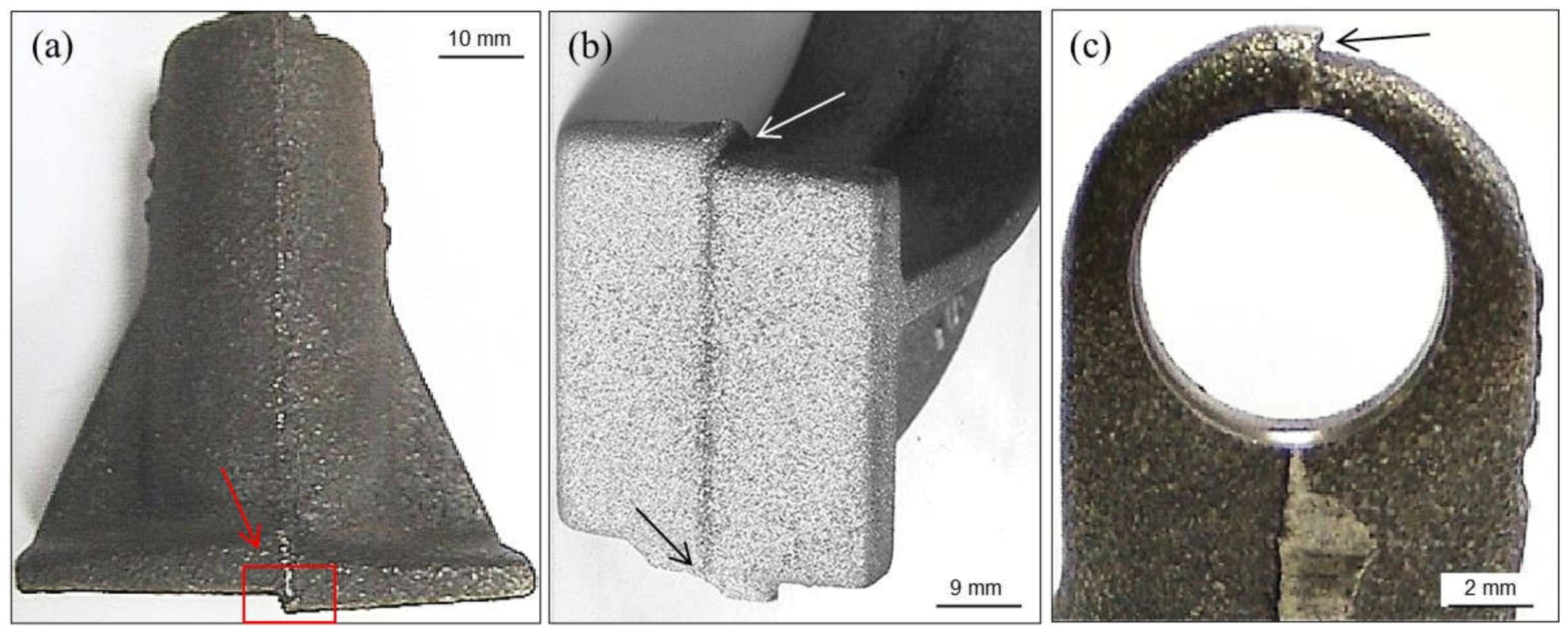
3.2.2. Fish-Eye Defect
- Use of proper bentonites for preparing the green sand mixtures.
- Avoid the use of any exothermic sleeve with a fluorine content greater than 0.10 wt.%.
- Ensure proper regeneration levels in green sand mixtures (regular additions of new silica sand). This defect also occurs when using other types of sand than silica (chromite, olivine, zirconium, etc.), as fluorine reacts with magnesium containing oxides.
- Avoid hot spot areas in castings and high casting temperatures.
- Maintain appropriate loss on ignition levels to minimize oxidation reactions.
- Optimize the sand mixing stage to reduce the moisture content required to achieve sufficient compactability of the prepared mixtures.
- Reduce fluorine contamination of sand blends when the fluorine content is greater than 0.030 wt.%.
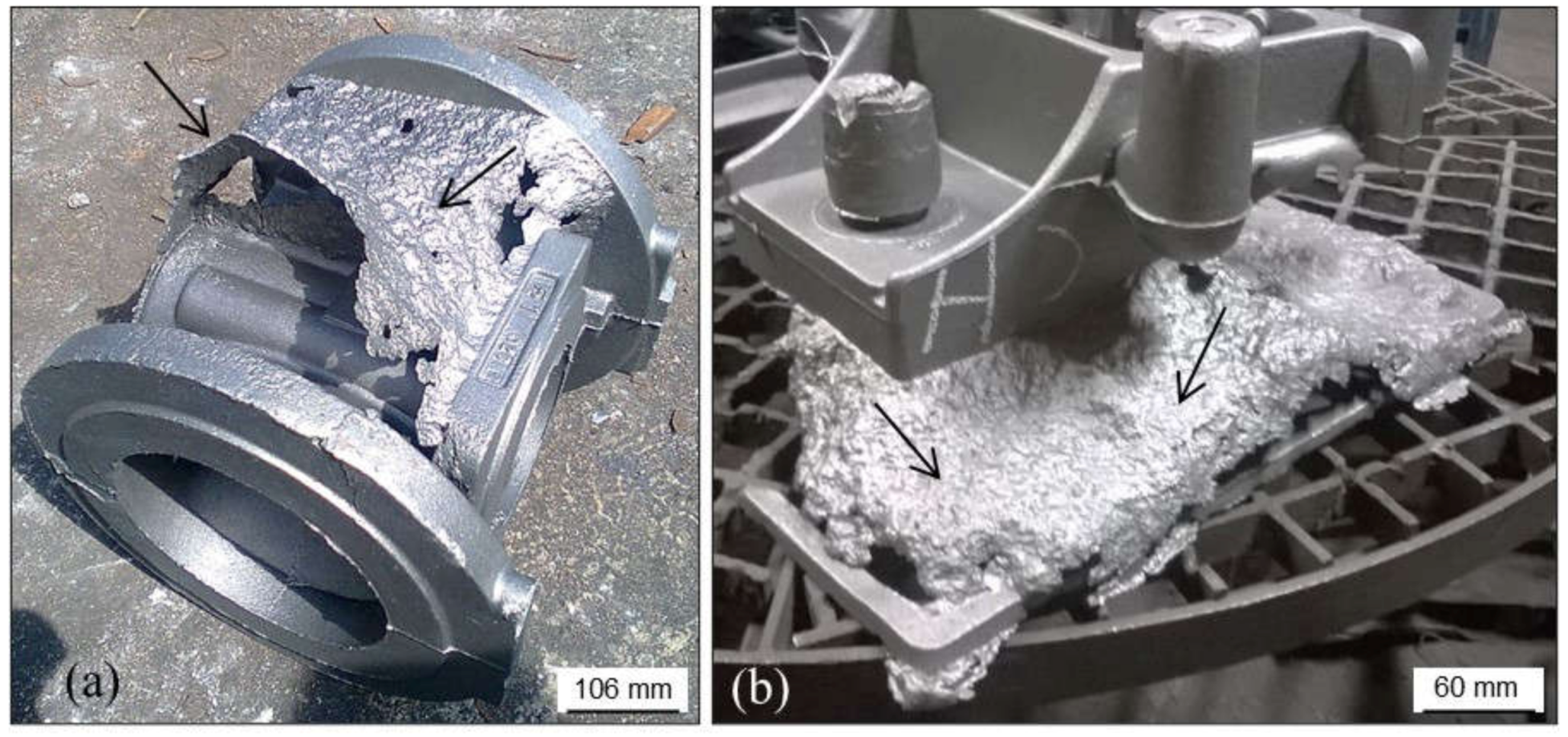
3.2.3. Surface Defect Due to Massive Contamination of the Sand
3.2.4. Hot Spot
3.2.5. Pearlitic Rim
3.2.6. Decarburization
3.2.7. Surface Degeneration of Spheroidal Graphite
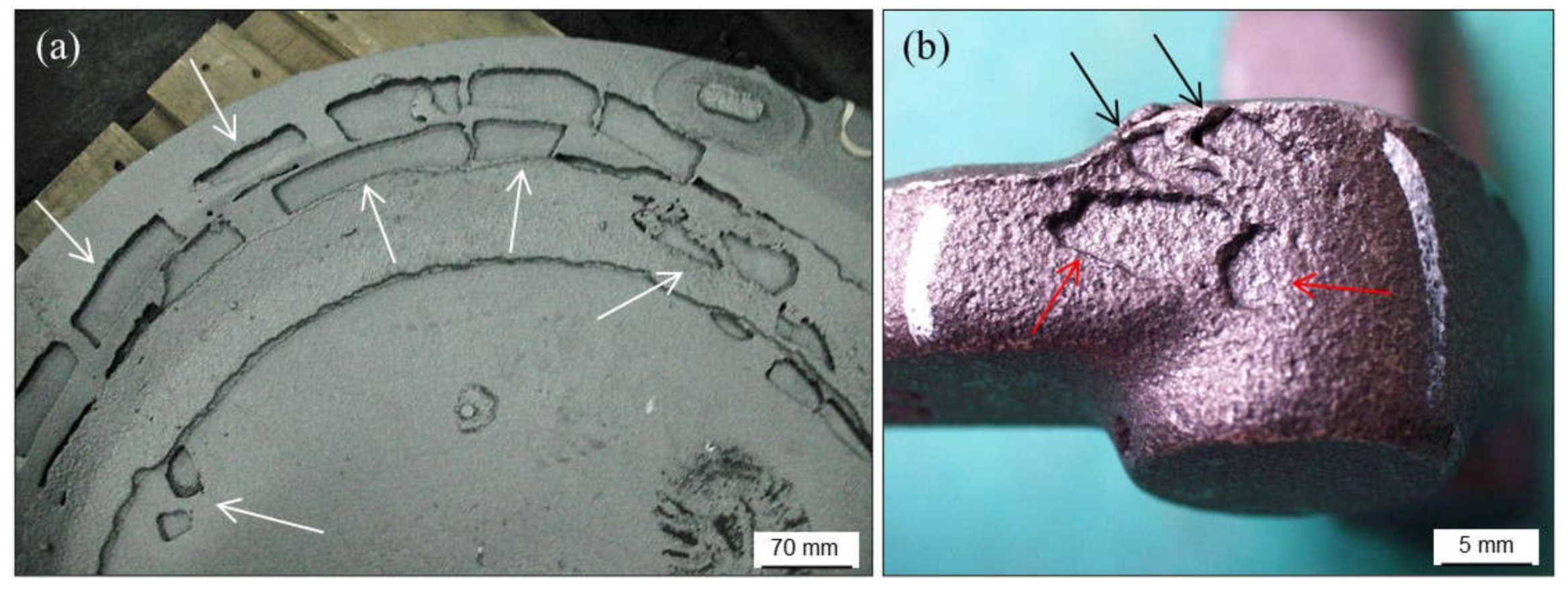
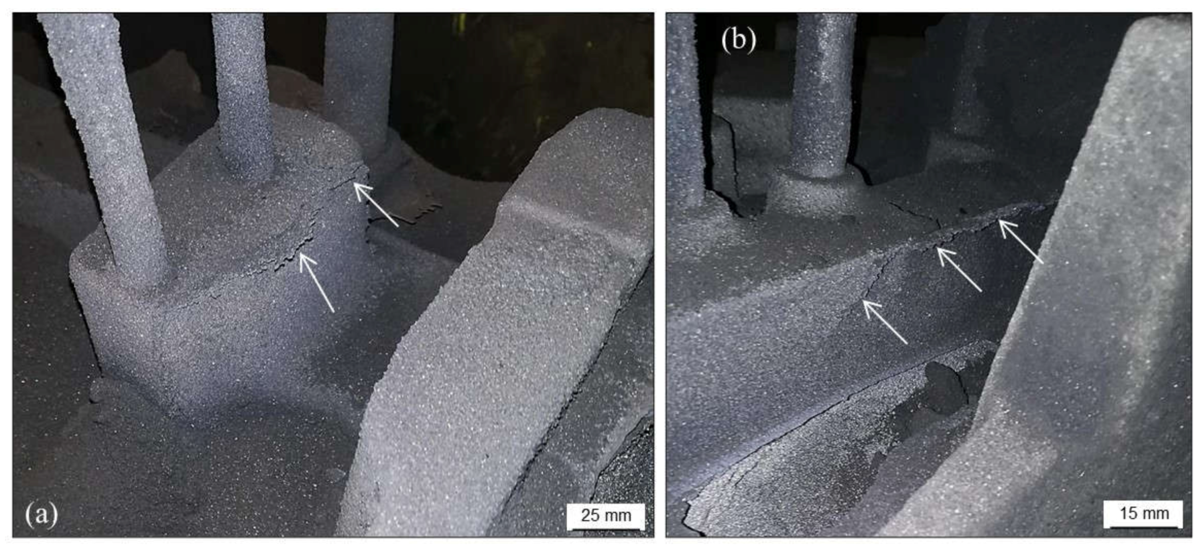
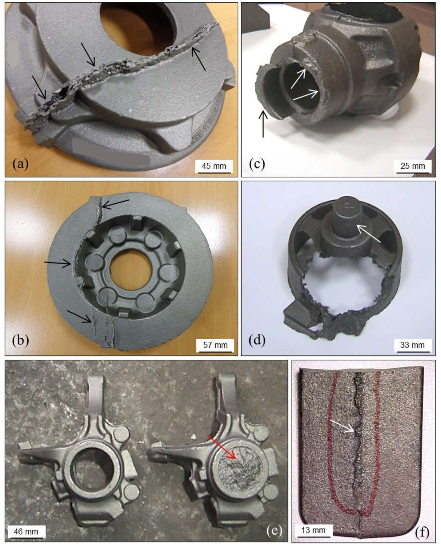
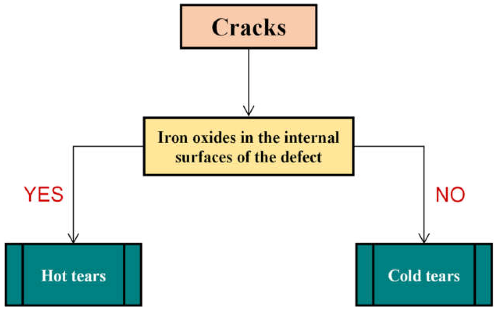
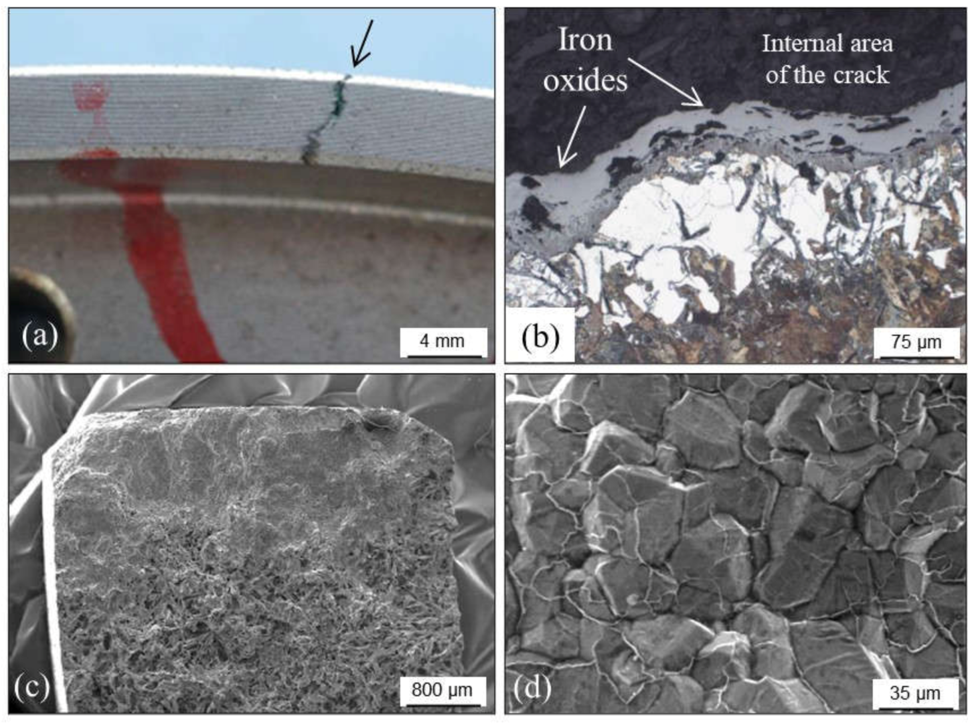
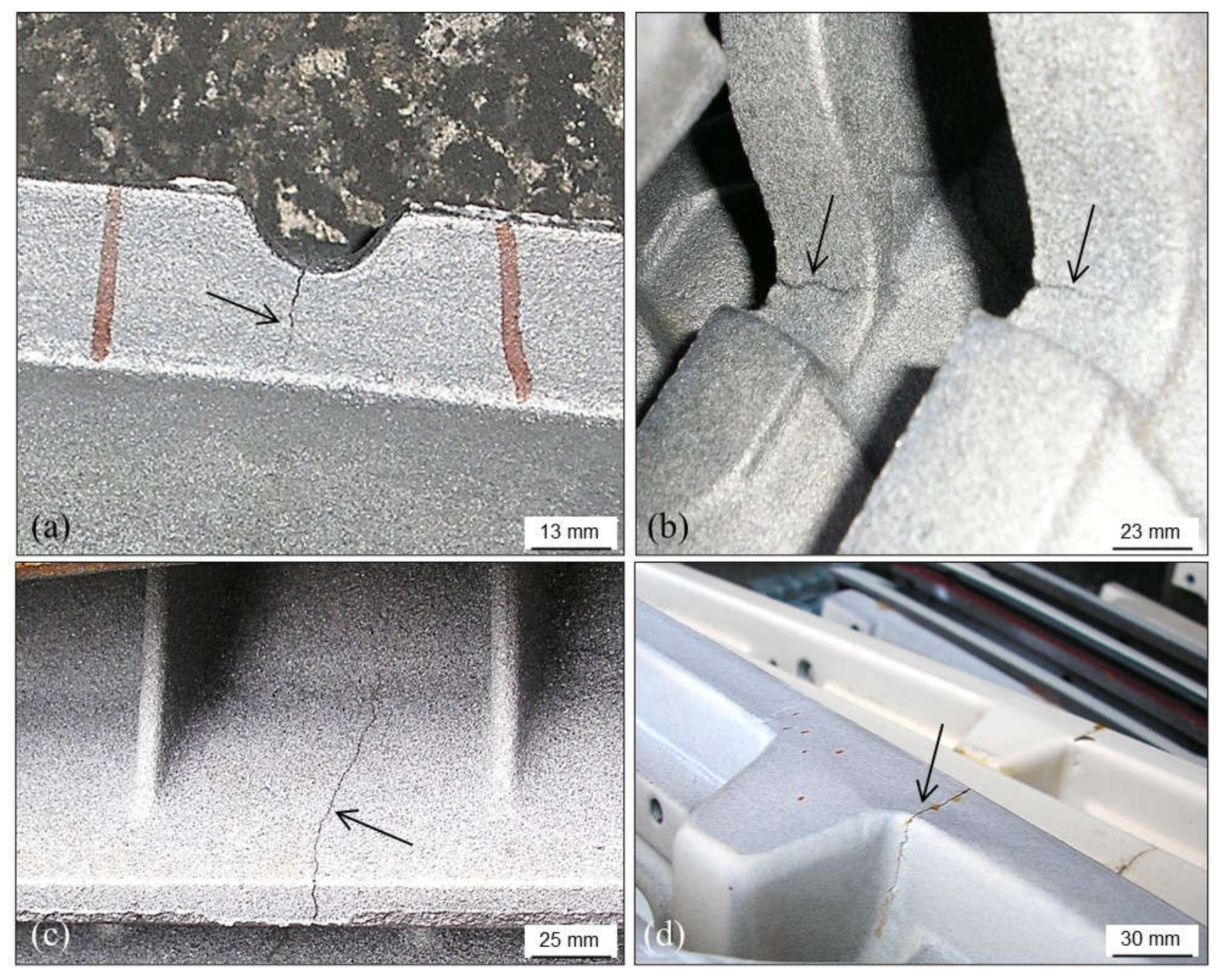
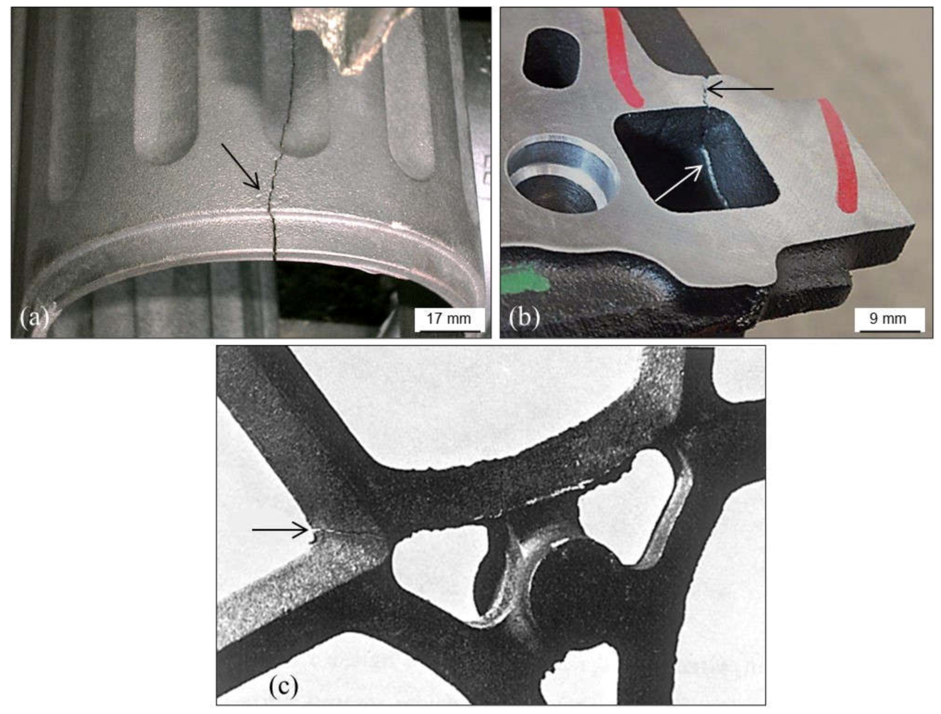
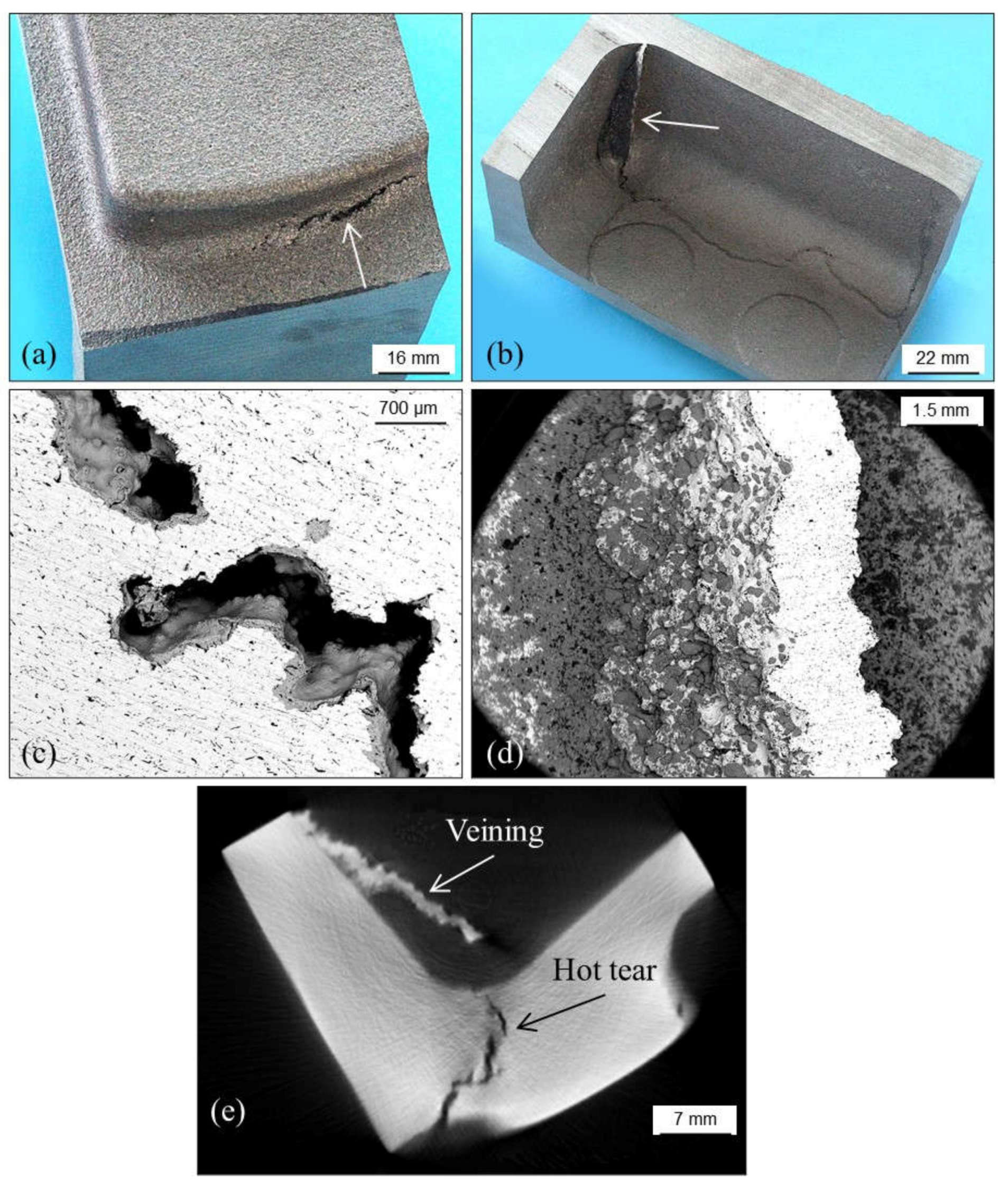
3.3. Cracks, Hot Tears and Cold Tears (Hot Cracks)
3.3.1. Hot Tears
- →
- Sulfur and phosphorus that delay solidification. Sulfur can be counteracted with manganese additions.
- →
- Chromium, when higher than 0.1 wt.%, leading to carbides in thin casting sections.
- →
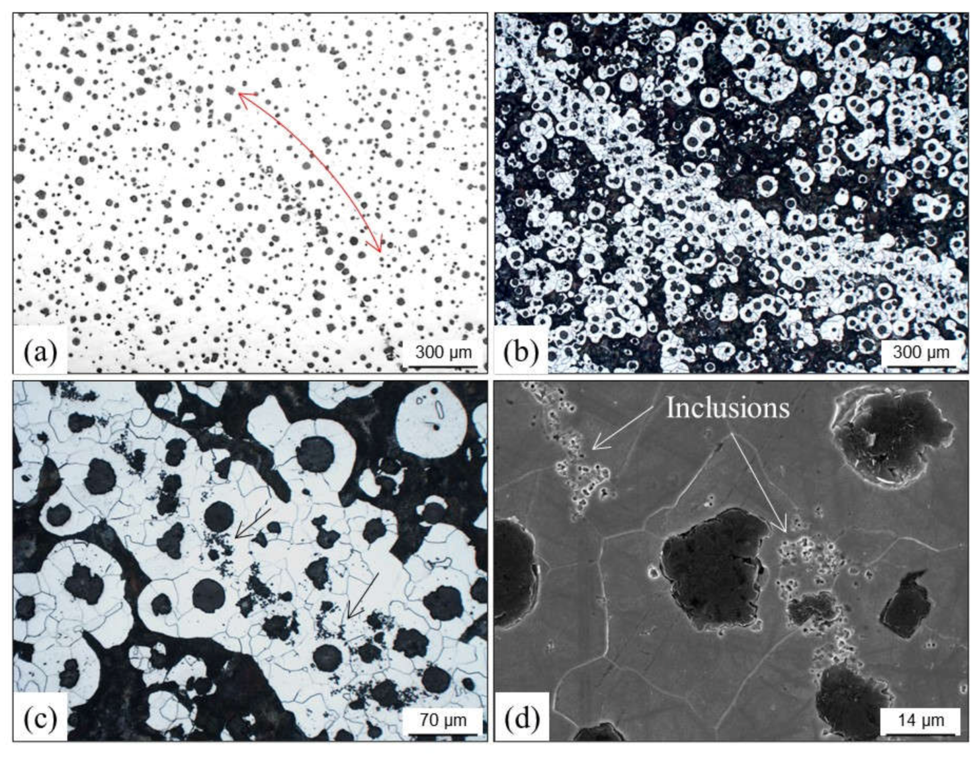
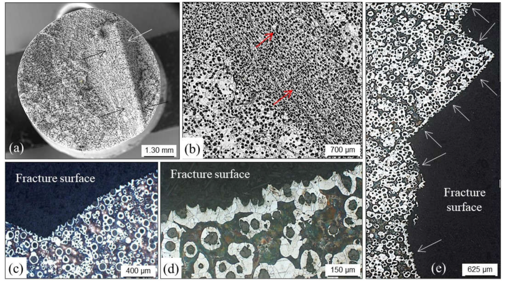
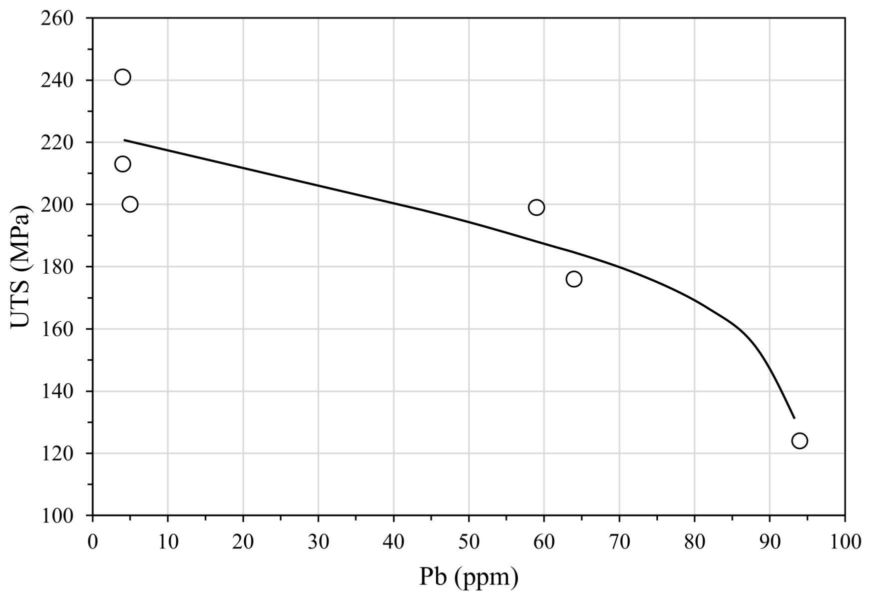
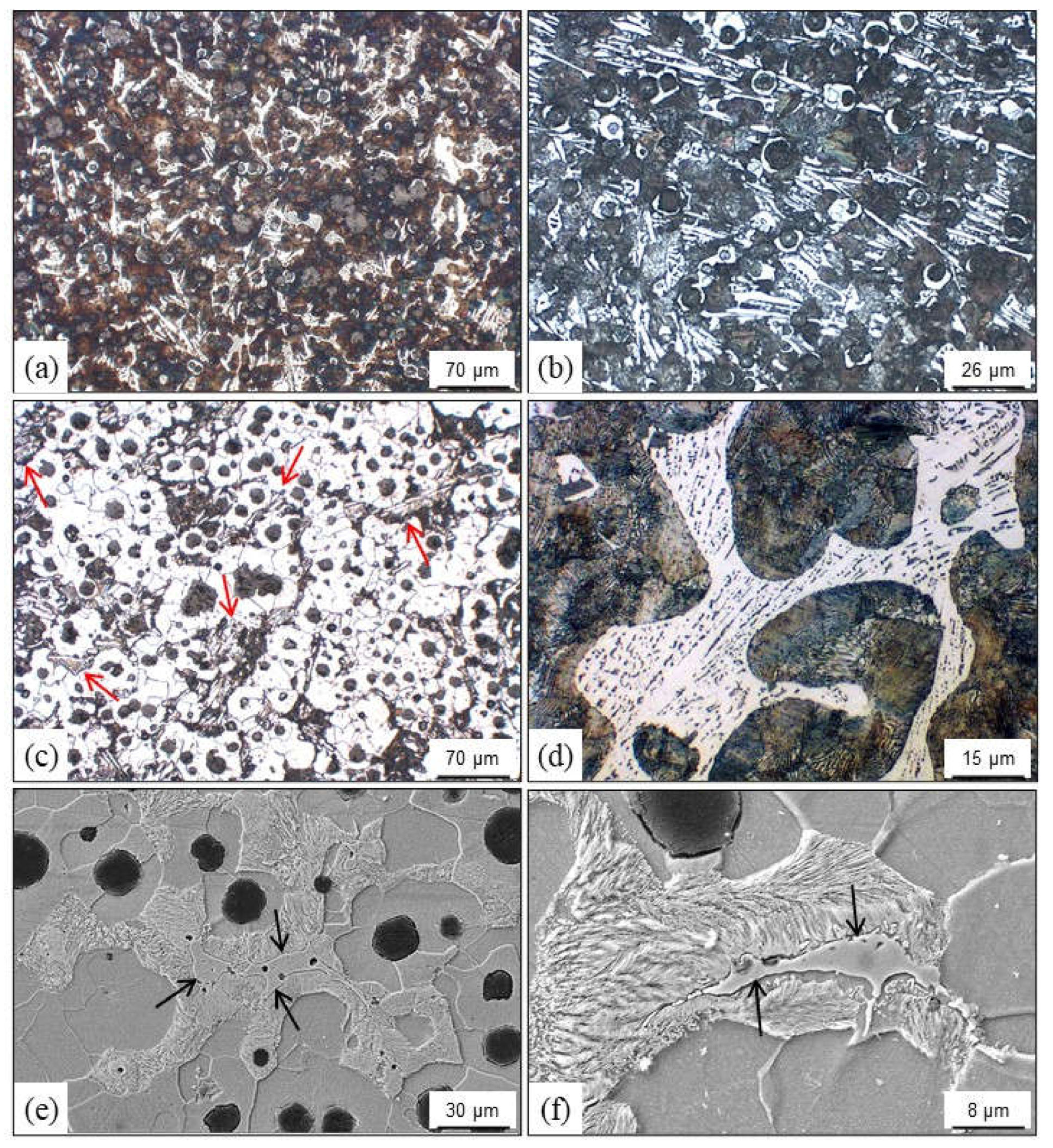
- Lead, when higher than 4 ppm, coming from non-ferrous scrap and coatings used in steel components.
- →
- Tin, when higher than 0.1 wt.%.
- →
- Antimony and boron together with lead that come from enameled scrap.
3.3.2. Cold Tears
4. Metal-Related Defects
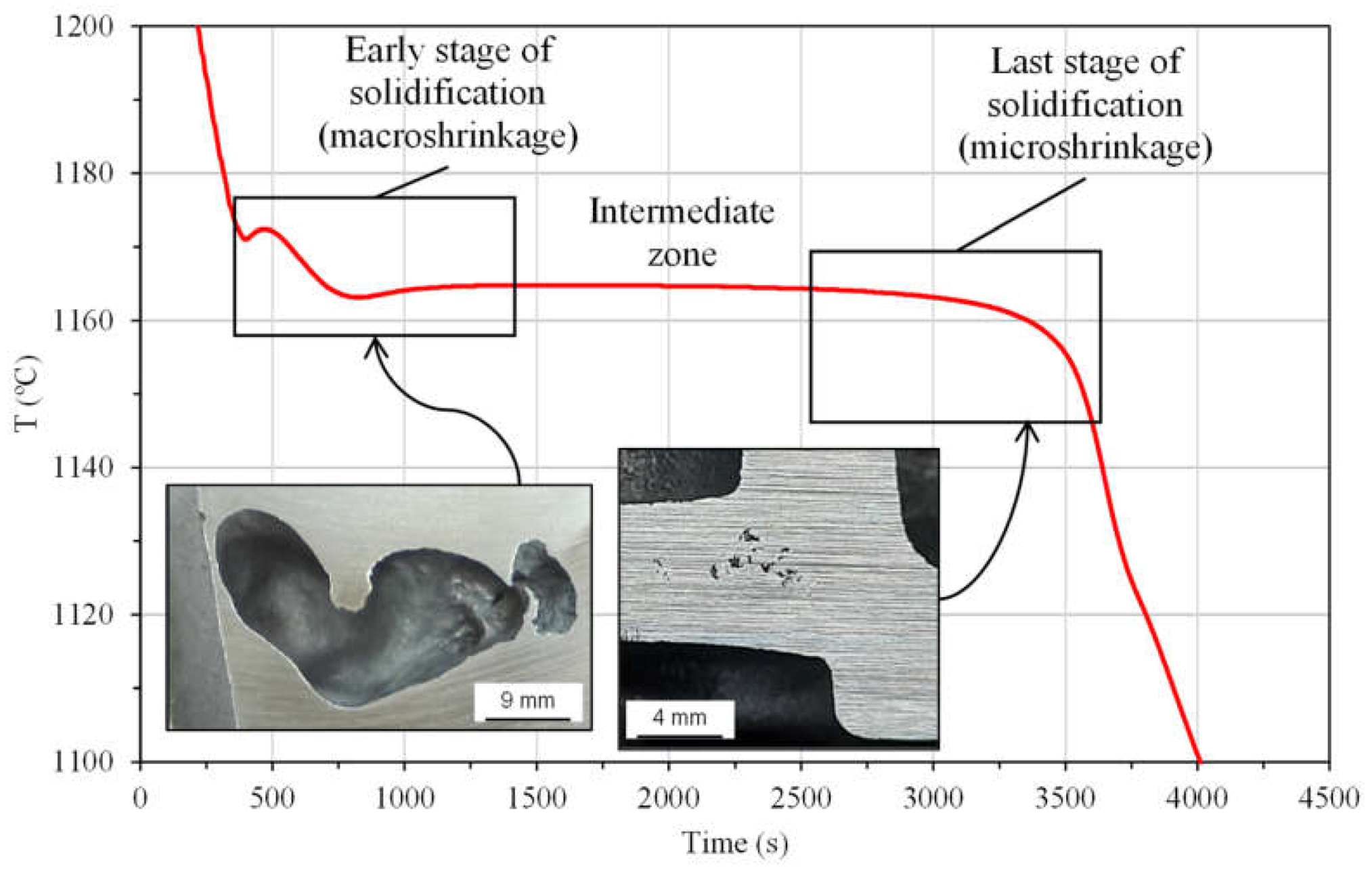
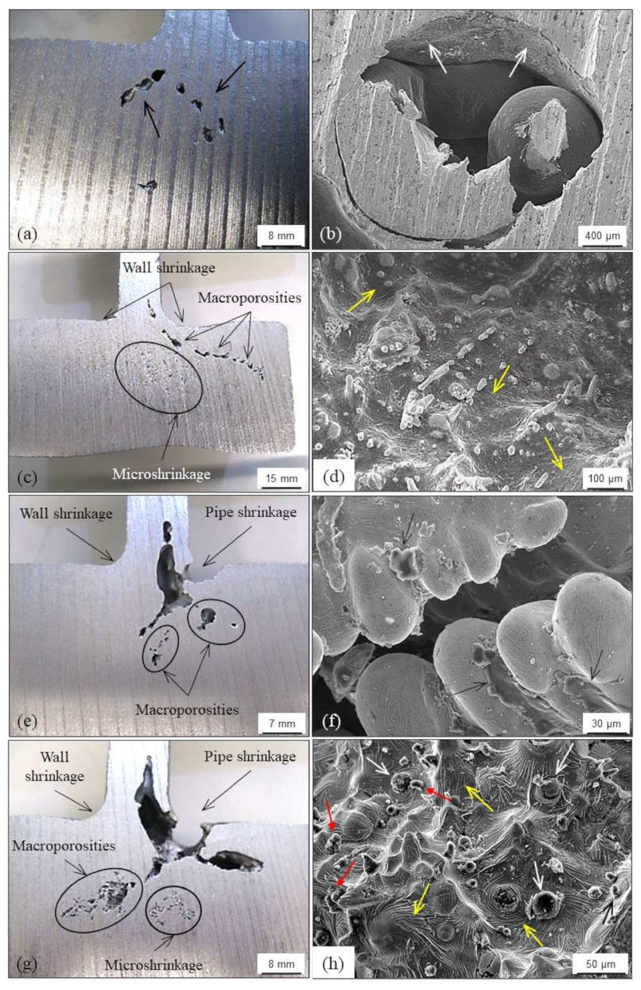
4.1. Shrinkage Porosities
4.1.1. Primary Shrinkage or Macroshrinkage
4.1.2. Secondary Shrinkage or Microshrinkage
4.1.3. False Shrinkage
4.2. Graphite Precipitation (White Cast Irons)
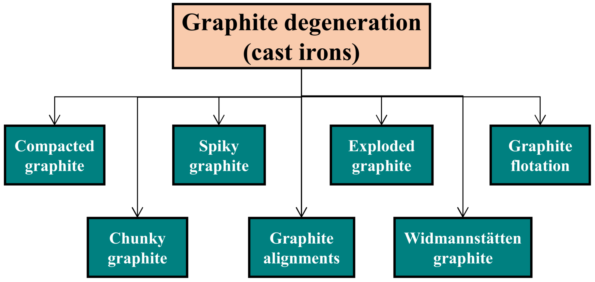
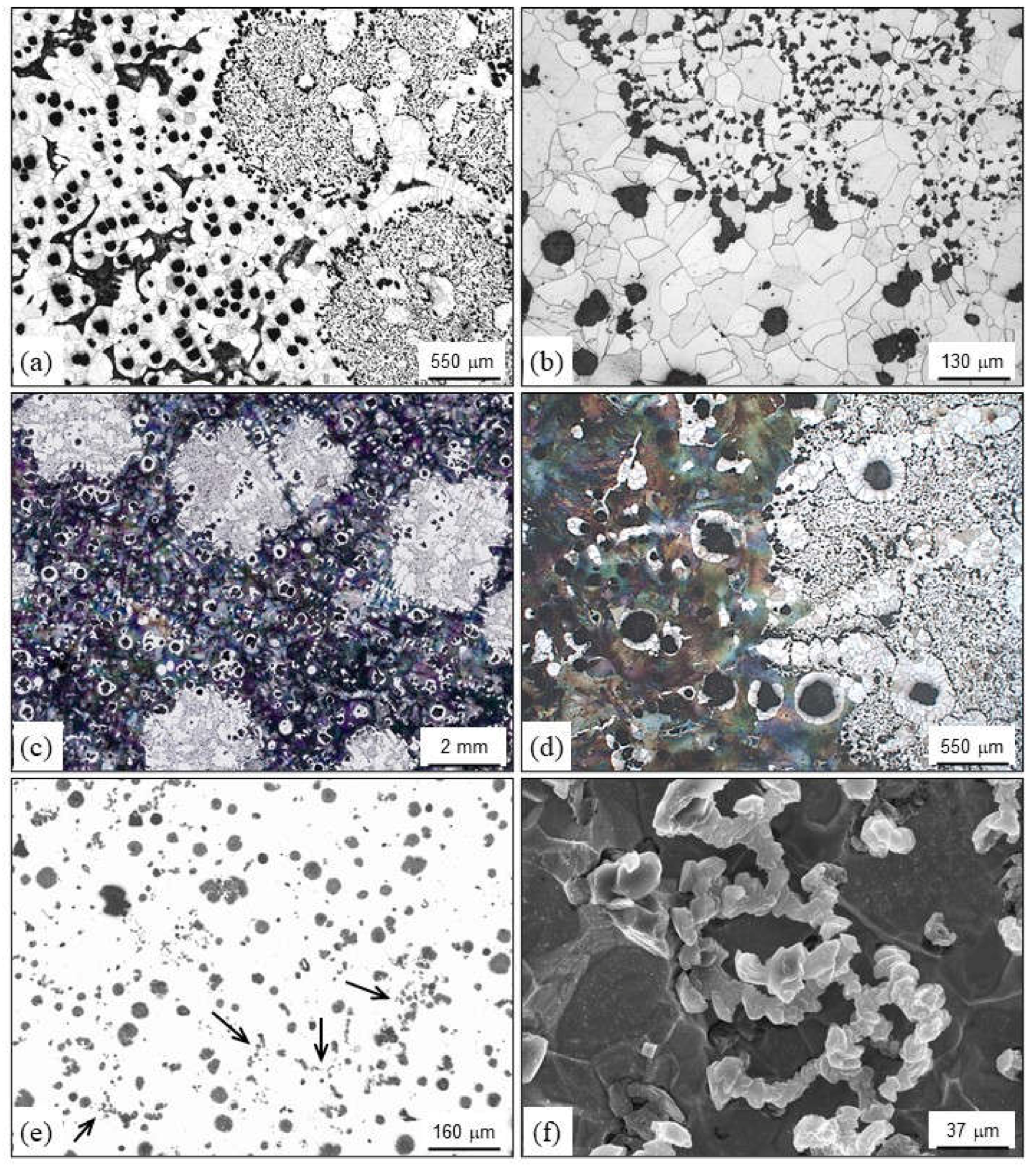
4.3. Graphite Degeneration
4.3.1. Compacted Graphite
4.3.2. Exploded Graphite
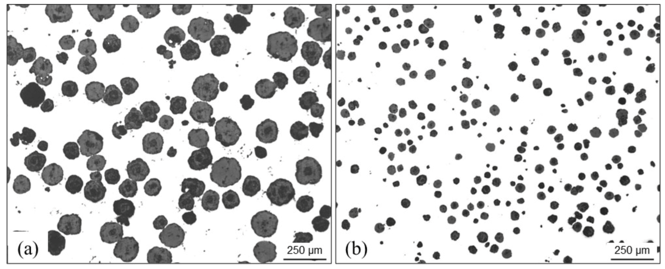
4.3.3. Graphite Flotation
4.3.4. Spiky Graphite
4.3.5. Chunky Graphite
4.3.6. Graphite Alignments
- High solidification rates in thin section castings in which the eutectic undercooling is increased.
- Delayed effects of inoculation, giving more time to austenite dendrites to develop.
4.3.7. Widmanstätten Graphite
4.4. Carbides and Inverse Chill
4.4.1. Carbide Precipitation: Chilling
- High solidification rates (small casting sections, use of chills and/or die molds), casting sections located close to important burrs, etc.
- High contents of those alloying elements considered as carbide formers (chromium and vanadium) or carbide promoters because of limiting graphite growth (tellurium, magnesium, bismuth and rare earth elements).
- Melts of low graphite nucleation potential because of the use of highly oxidized metallic charges, long holding times in ladles and/or in melting furnaces, intense magnesium treatments and insufficient post-inoculation or a lack of it.
- Low carbon equivalent hypoeutectic alloys for which the silicon content plays an important role for graphite nucleation.
4.4.2. Inverse Chill
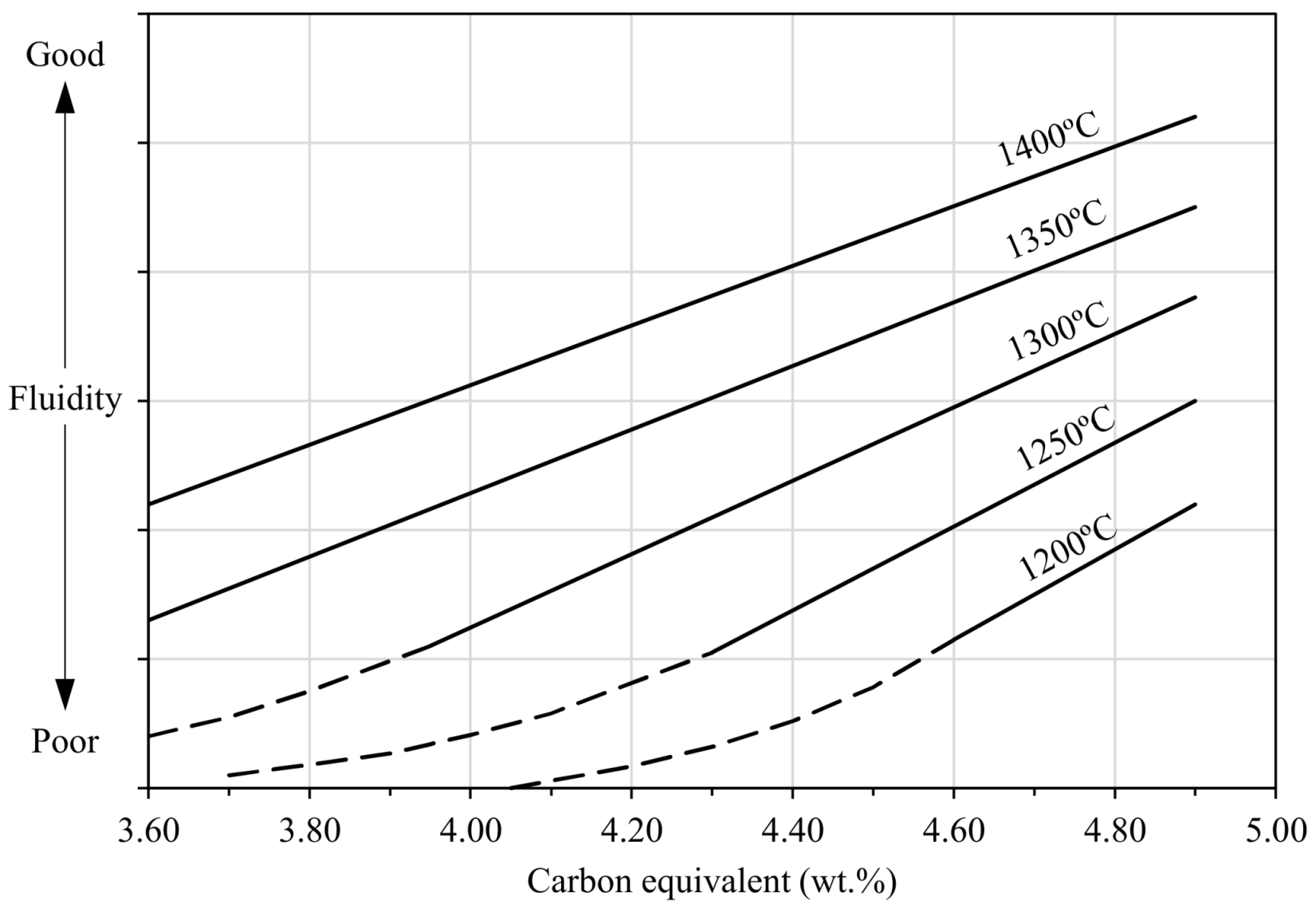
4.5. Cold Shut, Cold Lap
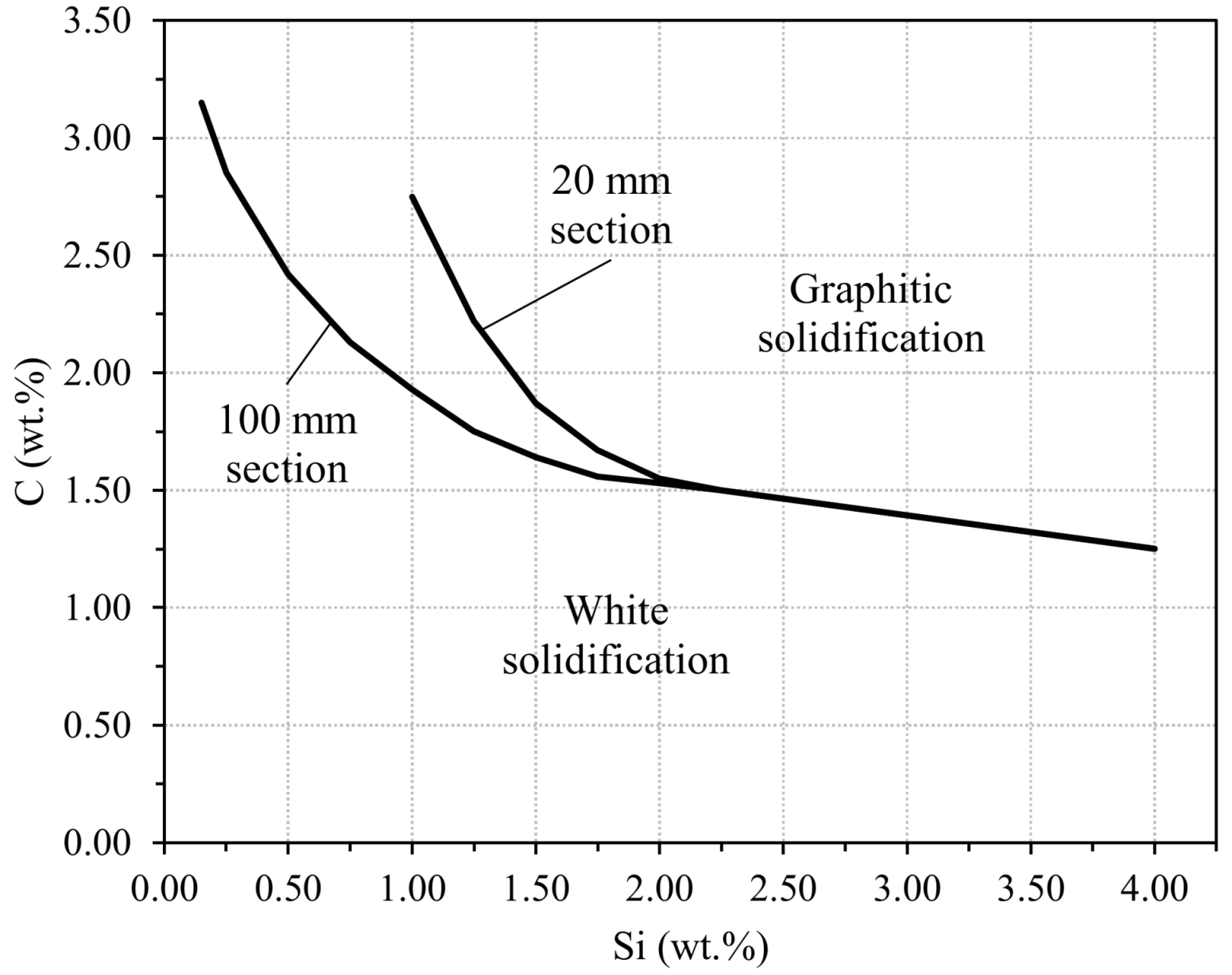
- Low pouring temperature, very low or very high carbon equivalent contents (see Figure 92) and high viscosity of melts due to the effect of alloying elements such as aluminum, phosphorus, etc., i.e., all those aspects which limit melt castability.
- High pouring time (too small sections in runners and ingates).
- The use of casting designs with small and large sections, which remove heat quickly from melts.
- Interrupted pouring steps (long pouring times and different parts of liquid metal entering in mold cavities).
- Low height difference between the top level of melts in the pouring cups when filling the molds and the top area of filling cavities (low dynamic and static pressure to correctly fill the entire cavities).
- Filling problems due to internal gas, which cannot be evacuated quickly to open air.
- In case of die molds, low temperature in any part of them.
5. Conclusions
Author Contributions
Funding
Acknowledgments
Conflicts of Interest
References
- ASM International. Casting, Metals Handbook, 9th ed.; ASM International: Almere, The Netherlands, 1988; Volume 15. [Google Scholar]
- Campbell, J. Castings; Butterworth-Heinemann: Oxford, UK, 1997; reprinted. [Google Scholar]
- Elliott, R. Cast Iron Technology; Butterworths: Petersburg, VA, USA, 1988. [Google Scholar]
- Hecht, M. La Santé des Pieces en Fontes à Graphite Spheroidal; ETIF: Sèvres, France, 2008. [Google Scholar]
- Farquhar, J.D. Nitrogen in ductile iron–A literature review. AFS Trans. 1979, 87, 433–438. [Google Scholar]
- Darken, L.S.; Gurry, R.W. Physical Chemistry of Metals; McGraw-Hill: New York, NY, USA, 1953. [Google Scholar]
- Johnson, B.D.; Heine, R.W. Nitrogen in molten iron processing and its effects. AFS Trans. 2000, 108, 163–169. [Google Scholar]
- Parent-Simonin, S.; Guyot, J. L’azote et l’hydrogène dans les fontes à graphite nodulaire. Fonderie 1983, 22, 15–28. [Google Scholar]
- BCIRA. Hydrogen Pinholing. In Control and Prevention of Casting Defects; BCIRA: Vancouver, BC, Canada, 1992. [Google Scholar]
- Gas Defects. In Analysis of Casting Defects; AFS: New York, NY, USA, 1966; Chapter 11; pp. 42–51.
- Meehanite. Example nº 28. In Manual of Casting Defects; International Meehanite Metal Company Limited: Reigate, Surrey, UK, 1978. [Google Scholar]
- IKO-Erbslöh. Manual of Casting Defects; IKO-Erbslöh: Gelsenkirchen, Germany, 1994; Pinholes; p. 63. [Google Scholar]
- AFS. Scar Seam Plates and Fusion. In Analysis of Casting Defects; AFS: New York, NY, USA, 1966; Chapter 10 and Chapter 25; pp. 38–41. [Google Scholar]
- Parkes, W.B. Clay Bonded Foundry Sand; Elsevier: Amsterdam, The Netherlands, 1971; p. 268. [Google Scholar]
- Levelink, H.G.; Vanden Berg, H. Water explosion as a cause of casting defects. AFS Trans. 1968, 76, 241–250. [Google Scholar]
- BCIRA. Surface Defects. In Control and Prevention of Casting Defects; BCIRA: Vancouver, BC, Canada, 1992. [Google Scholar]
- Rowley, M.T. International Atlas of Casting Defects; American Foundry Society: New York, NY, USA, 1999; p. 202. [Google Scholar]
- Thiel, J. Thermal expansion of chemically bonded silica sand. AFS Trans. 2011, 119, 369–378. [Google Scholar]
- St. Kowalski, J. Thermal aspects of temperature transformations in silica sand. Arch. Foundry Eng. 2010, 10, 111–114. [Google Scholar]
- Svidró, J.; Diószegi, A.; Tóth, L.; Svidró, J.T. The influence of thermal expansion of unbonded foundry sands on the deformation of resin bonded cores. Arch. Metall. Mater. 2017, 62, 795–798. [Google Scholar] [CrossRef] [Green Version]
- Svidró, J.; Svidró, J.T.; Diószegi, A. The role of purity level in foundry silica sand on its thermal properties. J. Phys. Conf. Ser. 2020, 1527, 012039. [Google Scholar] [CrossRef]
- Parkes, W.B. Clay Bonded Foundry Sand; Elsevier: Amsterdam, The Netherlands, 1971; p. 283. [Google Scholar]
- Meehanite. Example nº 14. In Manual of Casting Defects; International Meehanite Metal Company Limited: Reigate, Surrey, UK, 1978. [Google Scholar]
- Taylor, H.F.; Fleming, M.C.; Wulff, J. Foundry Engineering; John Wiley & Sons: Hoboken, NJ, USA, 1967; p. 231. [Google Scholar]
- Meehanite. Example nº 3. In Manual of casting defects; International Meehanite Metal Company Limited: Reigate, Surrey, UK, 1978. [Google Scholar]
- BCIRA. Inclusions from moulds, cores, metal treatment and handling. In Control and Prevention of Casting Defects; BCIRA: Vancouver, BC, Canada, 1992. [Google Scholar]
- BCIRA. Broadsheet 20. In Prevention of Dross Defects in Nodular (SG) Iron Casting; BCIRA: Vancouver, BC, Canada, 1987. [Google Scholar]
- Meehanite. Example nº 30. In Manual of Casting Defects; International Meehanite Metal Company Limited: Reigate, Surrey, UK, 1978. [Google Scholar]
- Parkes, W.B. Clay Bonded Foundry Sand; Elsevier: Amsterdam, The Netherlands, 1971; p. 275. [Google Scholar]
- Bindernagel, I.; Kolorz, A.; Orths, A. Controlled additions of hydrocarbon components to molding sand mixtures improve casting surface finish. AFS Trans. 1975, 83, 557–560. [Google Scholar]
- BCIRA. Broadsheet 222. In Lustrous-Carbon Defects in Castings; BCIRA: Vancouver, BC, Canada, 1987. [Google Scholar]
- Campbell, J.; Naro, R.L. Lustrous carbon on gray iron. AFS Trans. 2010, 118, 10–136. [Google Scholar]
- Jezierski, J.; Jureczko, M.; Dojka, R. The Impact of process factors on creating defects, mainly lustrous carbon, during the production of ductile iron using the lost-foam casting (LFC) method. Metals 2020, 10, 1022. [Google Scholar] [CrossRef]
- Comité Internacional de las Asociaciones Técnicas de Fundición. Mejora de la Calidad de las Piezas Fundidas; Luis Cárcamo: Madrid, Spain, 1974. [Google Scholar]
- Dirt, slag and other inclusions. In Analysis of Casting Defects; AFS: New York, NY, USA, 1966; Chapter 6; pp. 16–22.
- Meehanite. Example nº 19. In Manual of Casting Defects; International Meehanite Metal Company Limited: Reigate, Surrey, UK, 1978. [Google Scholar]
- Swells, strains and sags. In Analysis of Casting Defects; AFS: New York, NY, USA, 1966; Chapter 30; pp. 120–124.
- Parkes, W.B. Clay Bonded Foundry Sand; Elsevier: Amsterdam, The Netherlands, 1971; p. 266. [Google Scholar]
- Shifts (also core raise). In Analysis of Casting Defects; AFS: New York, NY, USA, 1966; Chapter 26; pp. 104–107.
- Meehanite. Example nº 29. In Manual of CASTING defects; International Meehanite Metal Company Limited: Reigate, Surrey, UK, 1978. [Google Scholar]
- Aufderheide, R.C.; Showman, R.E.; Close, J.; Zins, E.J. Eliminating fish-eye defects in ductile casting. AFS Trans. 2002, 110, 2–47. [Google Scholar]
- BCIRA. Broadsheet 155. In Avoiding Graphite-Free Surface Layers on Grey Iron Castings Made in Greensand Moulds; BCIRA: Vancouver, BC, Canada, 1987. [Google Scholar]
- The Soremetal Book of Ductile Iron; Rio Tinto Iron & Titanium Inc.: Montréal, QC, Canada, 2004.
- Meehanite. Example nº 27. In Manual of CASTING Defects; International Meehanite Metal Company Limited: Reigate, Surrey, UK, 1978. [Google Scholar]
- IKO-Erbslöh. Manual of Casting Defects; IKO-Erbslöh: Gelsenkirchen, Germany, 1994; Graphite Degeneration; pp. 32–35. [Google Scholar]
- Golovan, N.A.; Dudni, K.J.A.; Dubrov, V.V. Bildung von Lamellengraphit in der Oberflächenzone von Gußstücken aus GGG. Lit. Proizv. 1977, 7, 35–36. [Google Scholar]
- Meehanite. Example nº 25. In Manual of Casting Defects; International Meehanite Metal Company Limited: Reigate, Surrey, UK, 1978. [Google Scholar]
- BCIRA. Broadsheet 64. In Cracking in Grey Iron Casting; BCIRA: Vancouver, BC, Canada, 1987. [Google Scholar]
- Regordosa, A. Influència dels Paràmetres de Procès Sobre la Formació D’escòria i Dels Defectes de Contracció en les Foses de Ferro Amb Grafit Esferoïdal. Ph.D. Thesis, Universitat de Barcelona, Barcelona, Spain, May. 2017. [Google Scholar]
- Parkes, W.B. Clay Bonded Foundry Sand; Elsevier: Amsterdam, The Netherlands, 1971; p. 267. [Google Scholar]
- AFS. Shrinkage cavities and depressions. In Analysis of Casting Defects; AFS: New York, NY, USA, 1966; Chapter 28. [Google Scholar]
- BCIRA. Broadsheet 164-2. In Mottle in Malleable Irons; BCIRA: Vancouver, BC, Canada, 1987. [Google Scholar]
- Reynaud, A. Oligo-Éléments et Fontes; ETIF: Sèvres, France, 2005. [Google Scholar]
- Internal Report Fundación Azterlan; Azterlan: Durango, Spain, 2018.
- AFS. Carbon flotation (kish) and other gross segregation. In Analysis of Casting Defects; AFS: New York, NY, USA, 1966; Chapter 3; pp. 6–8. [Google Scholar]
- Sertucha, J.; Artola, G.; de La Torre, U.; Lacaze, J. Chunky graphite in low and high silicon spheroidal graphite cast irons–occurrence, control and effect on mechanical properties. Materials 2020, 13, 5402. [Google Scholar] [CrossRef] [PubMed]
- González-Martínez, R.; de la Torre, U.; Lacaze, J.; Sertucha, J. Effects of high silicon contents on graphite morphology and room temperature mechanical properties of as-cast ferritic ductile cast irons. Part I–Microstructure. Mater. Sci. Eng. A 2018, 712, 794–802. [Google Scholar] [CrossRef] [Green Version]
- BCIRA. Broadsheet 138-2. In Abnormal Graphite Forms in Cast Iron; BCIRA: Vancouver, BC, Canada, 1987. [Google Scholar]
- Internal Report Fundación Azterlan; Azterlan: Durango, Spain, 2012.
- BCIRA. Broadsheet 50. In Harmful Effects of Trace Amounts of Lead in Flake Graphite Cast Irons; BCIRA: Vancouver, BC, Canada, 1987. [Google Scholar]
- BCIRA. Broadsheet 224. In Avoiding White Iron Formation or “Chill” in Grey Irons; BCIRA: Vancouver, BC, Canada, 1987. [Google Scholar]
- BCIRA. Broadsheet 55. In Inverse Chill in Flake Graphite Cast Iron; BCIRA: Vancouver, BC, Canada, 1987. [Google Scholar]
- BCIRA. Broadsheet 159. In Factors Affecting the Fluidity of Molten Cast Iron; BCIRA: Vancouver, BC, Canada, 1987. [Google Scholar]


| Composition | Inoculation | Pipe | Wall | Macroporosity | Microshrinkage |
|---|---|---|---|---|---|
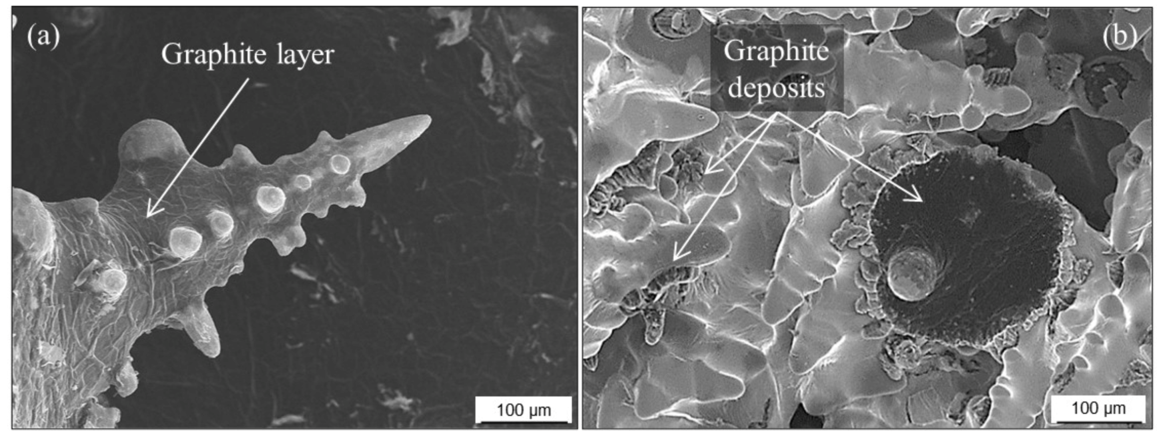
| Hypereutectic | Yes | No defect | No defect | Continuous graphite layers on smooth surfaces | No defect |
| No | No defect | Yes | Continuous graphite layers on rounded dendrites | Continuous graphite layer on sharp dendrites | |
| Hypoeutectic | Yes | Smooth surfaces | Yes | Continuous graphite layers on rounded dendrites Graphite nodules together with rounded dendrites | No defect |
| No | Smooth surfaces | Yes | Discontinuous graphite layers on rounded dendrites | Discontinuous graphite layers on rounded dendrites Shrunk surfaces on dendrites |
| Alloy | Matrix | HBW | UTS (MPa) | YS (MPa) | A (%) | TC * (W·K−1·m−1) |
|---|---|---|---|---|---|---|
| LGI | pearlitic | 175–230 | 230–300 | 115–210 | 0–1 | 44–52 |
| CGI | ferritic | 130–190 | 330–410 | 240–350 | 5–10 | 40–50 |
| pearlitic | 215–250 | 400–580 | 345–415 | 2–5 | 31–42 | |
| SGI | ferritic | 140–200 | 400–600 | 285–315 | 15–25 | 32–38 |
| pearlitic | 240–300 | 600–800 | 375–480 | 3–15 | 23–32 |
| Area | Nodularity (%) | Average Diameter of Nodules (µm) | Nodule Count (mm−2) | UTS (MPa) | YS (MPa) | A (%) |
|---|---|---|---|---|---|---|
| No defect | >90 | 45.0 | 90 | 390 | 230 | 15.0 |
| Flotation | >90 | 101.0 | 45–50 | 232 | 191 | 5.8 |
| Sample | fSpiky_A | UTS (MPa) | YS (MPa) | A (%) |
|---|---|---|---|---|
| 2 | 0.24 | 444 | 441 | 1.0 |
| 3 | 0.28 | 451 | 444 | 0.5 |
| 4 | 0.27 | 459 | 425 | 1.5 |
| 5 | 0.12 | 487 | 430 | 3.5 |
| 6 | 0.18 | 486 | 430 | 3.0 |
| Reference | 0.00 | 565 | 456 | 16.7 |
| Low Si Alloy | fChunky_A | UTS (MPa) | YS (MPa) | A (%) | High Si Alloy | fChunky_A | UTS (MPa) | YS (MPa) | A (%) |
|---|---|---|---|---|---|---|---|---|---|
| 1 | 0.78 | 315 | 285 | 1.0 | 1 | 0.98 | 530 | 470 | 5.0 |
| 2 | 0.00 | 372 | 286 | 5.5 | 2 | 0.59 | 533 | 474 | 3.0 |
| 3 | 0.22 | 335 | 274 | 3.0 | 3 | 0.69 | 529 | 470 | 2.5 |
| 4 * | 0.17 | 420 | 283 | 11.0 | 4 | 0.69 | 545 | 466 | 5.0 |
| 5 | 0.00 | 402 | 284 | 6.0 | 5 | 0.97 | 529 | 468 | 4.5 |
Publisher’s Note: MDPI stays neutral with regard to jurisdictional claims in published maps and institutional affiliations. |
© 2022 by the authors. Licensee MDPI, Basel, Switzerland. This article is an open access article distributed under the terms and conditions of the Creative Commons Attribution (CC BY) license (https://creativecommons.org/licenses/by/4.0/).
Share and Cite
Sertucha, J.; Lacaze, J. Casting Defects in Sand-Mold Cast Irons—An Illustrated Review with Emphasis on Spheroidal Graphite Cast Irons. Metals 2022, 12, 504. https://doi.org/10.3390/met12030504
Sertucha J, Lacaze J. Casting Defects in Sand-Mold Cast Irons—An Illustrated Review with Emphasis on Spheroidal Graphite Cast Irons. Metals. 2022; 12(3):504. https://doi.org/10.3390/met12030504
Chicago/Turabian StyleSertucha, Jon, and Jacques Lacaze. 2022. "Casting Defects in Sand-Mold Cast Irons—An Illustrated Review with Emphasis on Spheroidal Graphite Cast Irons" Metals 12, no. 3: 504. https://doi.org/10.3390/met12030504
APA StyleSertucha, J., & Lacaze, J. (2022). Casting Defects in Sand-Mold Cast Irons—An Illustrated Review with Emphasis on Spheroidal Graphite Cast Irons. Metals, 12(3), 504. https://doi.org/10.3390/met12030504