Article

Effect of Sealing Treatments on Erosion–Corrosion of a Fe-Based Amorphous Metallic Coating in 3.5 wt.% NaCl Solution with 2 wt.% Sand

1
Normal College, Shenyang University, 54 Lianhe Road, Shenyang 110044, China
2
CAS Key Laboratory of Nuclear Materials and Safety Assessment, Institute of Metal Research, Chinese Academy of Sciences, 62 Wencui Road, Shenyang 110016, China
*
Authors to whom correspondence should be addressed.
Metals 2022, 12(4), 680; https://doi.org/10.3390/met12040680
Submission received: 23 March 2022 / Revised: 10 April 2022 / Accepted: 13 April 2022 / Published: 15 April 2022

Abstract

:
In this study, a Fe-based amorphous metallic coating (AMC) was sealed with three sealants, i.e., stearic acid, aluminum phosphate and cerium salt, respectively. Two types of electrochemical tests, namely the ex situ electrochemical impedance spectroscopy test and the in situ potentiostatic polarization test, were conducted to evaluate the erosion–corrosion resistance of as-sprayed and as-sealed AMCs. The results show that the aluminum phosphate–sealed AMC exhibits the best erosion–corrosion resistance with the higher critical flow velocity compared with the as-sprayed AMC, which is attributed to the deep penetration of aluminum phosphate and high hardness of the sealed layer. In contrast, the sealants of stearic acid and cerium salt are easily removed by sand particle impacting, deteriorating their erosion–corrosion resistance.

1. Introduction

Erosion–corrosion is defined as the deterioration process of material in multiphase flow environments, caused by the interaction between mechanical erosion and electrochemical/chemical corrosion and erosion [1]. It is one of the main reasons for the premature failure of flow-handling components. Therefore, preventing facilities from erosion–corrosion damage is highly demanded. The liquid–solid two-phase flow consisting of corrosive media and solid particles is one of the most common fluids causing erosion–corrosion. It has been proved by Wang et al. [2] and Zheng et al. [3] that Fe-based amorphous metallic coatings (AMCs) exhibited superior erosion–corrosion resistance for 304 stainless steel in the liquid–solid two-phase flow, due to their high hardness and good corrosion resistance. They could be, therefore, used as protective coatings against erosion–corrosion for flow-handling components [4]. However, some defects, such as pores and cracks, are inevitable when preparing Fe-based AMCs. Zhang et al. [5] pointed out that pore defects, especially the through-pores, deteriorated the long-term corrosion resistance of Fe-base AMC by providing a direct path for corrosive media diffusing to the substrate. Moreover, Shin et al. [6] revealed that the erosion rates of a plasma-sprayed thermal barrier coating increased with the porosity. Farmer et al. [7] also suggested that low porosity improved the coating’s erosion–corrosion resistance. It has been a consensus that pore defects are the key factor affecting corrosion resistance [5] and erosion–corrosion resistance [2] of AMCs.
As a post-treatment process, sealing treatment can reduce the porosity of Fe-based AMCs effectively and, hence, improve corrosion resistance, which is associated with the blocking of diffusion channels by sealants [8,9,10]. Wu et al. [11] revealed that corrosion of Fe-based AMC was inhibited after sealing treatment, using epoxy. Our previous work also reported superior corrosion resistance of Fe-based AMCs sealed by sol–gel methods with different cerium salts [8]. Up until now, almost all studies have focused on the effect of sealing treatments on the corrosion performance of Fe-based AMCs [8,9,10,11,12], but little attention has been paid to erosion–corrosion. The previous work has reported that higher corrosion resistance of a material or surface treatment under the static condition does not always correspond to higher erosion–corrosion resistance, due to the contribution of mechanical damage [13]. Therefore, the effect of sealing treatments on the erosion–corrosion of Fe-based AMCs needs further clarification.
Among the employed sealants, stearic acid has good shielding and hydrophobic properties [14,15,16], and the sealing process is simple. Zhang et al. [17] reported that the Al-based AMC sealed with stearic acid showed the best corrosion resistance compared to those sealed with potassium dichromate and nickel acetate. Aluminum phosphate with a low viscosity could permeate into the inner pores of the coating, so that deep-level sealing can be achieved [12,18,19,20]. Cerium salt is an environmentally friendly corrosion inhibitor which can provide effective protection for metals [21,22]. It has been used as the sealant for a coating to suppress the further corrosion of substrate in the case of corrosive media penetrating to the coating/substrate interface [23,24,25]. Accordingly, the present work employed the aforementioned three kinds of sealants (stearic acid, aluminum phosphate and cerium salt) to seal a Fe-based AMC, aiming at clarifying their effects on inhibiting erosion–corrosion of the coating.
There are some methods to evaluate the erosion–corrosion performance by using rotating disc electrode (RDE), rotating cylinder electrode (RCE), rotating ring electrode (RRE), flow loop and impingement jet equipment [3,26,27,28,29,30,31]. In this paper, a homemade RDE setup was used to simulate the liquid–solid two-phase flow environment composed of 3.5 wt.% NaCl and 2 wt.% sand [29]. Ex situ surface morphology observation, surface roughness characterization and electrochemical impedance spectroscopy (EIS) measurements were conducted after erosion–corrosion for a certain time. In addition, the critical flow velocity for erosion–corrosion was evaluated by in situ potentiostatic polarization in an impingement jet apparatus, which is also an indicator of erosion–corrosion resistance [27,31,32,33]. The effects of sealants on erosion–corrosion mechanisms were discussed, and this provided a theoretical basis for the selection of sealants for Fe-based AMCs in sand-containing seawater.

2. Experimental

2.1. Materials and the Preparation of Three Sealed Coatings

The Fe54.2Cr18.3Mo13.7Mn2.0W6.0B3.3C1.1Si1.4 (wt.%) AMC with high porosity was used in this study; it was sprayed by HVOF thermal spray technology. The powders were produced by argon atomized at a dynamic pressure of 7 MPa after heating to 1600 K, and the as-atomized powders ranging from 15 to 45 μm were sprayed onto the 10CrNi3MoV carbon steel substrate. The spraying parameters were as follows: the oxygen flow, kerosene flow and air flow were 252, 72 and 399 standard cubic feet, respectively; the spraying distance was 250 mm; the feed rate was 20 g/mm; and the traverse velocity was 800 mm/s [10]. The phase composition of the as-sprayed coating was identified by X-ray diffractometer (XRD, Rigaku D/max 2400), as shown in Figure 1. A broad peak of 2θ = 40–50° appears on the XRD spectrum of the as-sprayed coating, indicating the amorphous structure.
Prior to sealing treatment, the as-sprayed AMC was ground with rougher 240 grit abrasive papers, so as to improve the wettability between the coating and the sealant, and then it was degreased by alcohol, washed with distilled water and dried in air.
(1)
Preparation of stearic acid–sealed AMC (SAS coating):
Firstly, stearic acid inside a beaker was heated above 85 °C, using a thermostatic water bath until, it was fully melted from a solid state into a liquid state. After that, Fe-based AMC was immersed into the above sealant for 1 h, followed by taking out. Finally, the excess sealant was removed from the surface by using 240 grit abrasive papers, until Fe-based AMC at the non-porous region was exposed.
(2)
Preparation of aluminum phosphate–sealed AMC (APS coating):
It mainly utilized a series of reactions between aluminum hydroxide and phosphoric acid at different temperatures to form the aluminum phosphate sealant with a three-dimensional network structure in the coating defects [9,34,35,36]. In addition, ultrasonic excitation technology was used to promote more sealant to penetrate the inner pores of the coating. The details on the synthesis process of aluminum phosphate sealant and the preparation process of APS coating were described in our earlier work [9]. Similarly, this sealed coating was ground with 240 grit abrasive papers to remove the excess sealant on the coating surface.
(3)
Preparation of cerium salt–sealed AMC (CSS coating):
The mixed solution consisting of 10 g/L Ce(NO3), 0.3 g/L H2O2 and 1 g/L H3BO3 was heated to 30 °C, using a thermostatic water bath. The Fe-based AMC was immersed in the above solution and kept at a constant temperature for 3 h. As such, the CSS coating was obtained.
All of the above chemicals were of analytical reagent grade, purchased from Sinopharm Group Shenyang Co., Ltd, China.

2.2. Evaluation of Erosion–Corrosion Resistance

Two types of electrochemical measurements, including the ex situ EIS test and the in situ potentiostatic polarization test, were used to evaluate erosion–corrosion resistance of the studied coatings. A homemade RDE setup was employed to simulate the erosion–corrosion environment [29], as shown in Figure 2, where the samples were fixed around the ring-like region of the disk, and then the disk was driven to rotate in the liquid–solid slurry by the motor. It was reported that the rotating disk could be well-matched with the hydrodynamic model; thus, it is appropriate to study the erosion–corrosion performance of the coating in the laboratory, using RDE [37]. The slurry was composed of 3.5 wt.% NaCl solution and 2 wt.% silica sand, and the relative flow velocity between slurry and samples was approximately 7 m/s. In addition, the angle of slurry impinged on the sample surface was nearly zero. The used sand was angular, with an average particle size of 152 μm. Unless specified, the erosion–corrosion tests in the following text are those conducted by using the rotating disc apparatus. After erosion–corrosion tests for 0, 0.5, 1.5, 3, 6 and 12 h, the coatings were taken out, washed with distilled water and dried in hot air, and then ex situ EIS measurements were conducted at the open-circuit potential in the frequency range from 100 kHz to 10 mHz, with a sinusoidal amplitude of 10 mV, using a Gamry Interface 1000 electrochemical workstation. A conventional three-electrode cell was applied, consisting of a saturated calomel electrode (SCE) as the reference electrode that was connected to the cell via a Luggin probe, a platinum counter electrode and a sample with an exposed area of 7 cm2 as the working electrode. Three parallel samples were measured to ensure reproducibility.
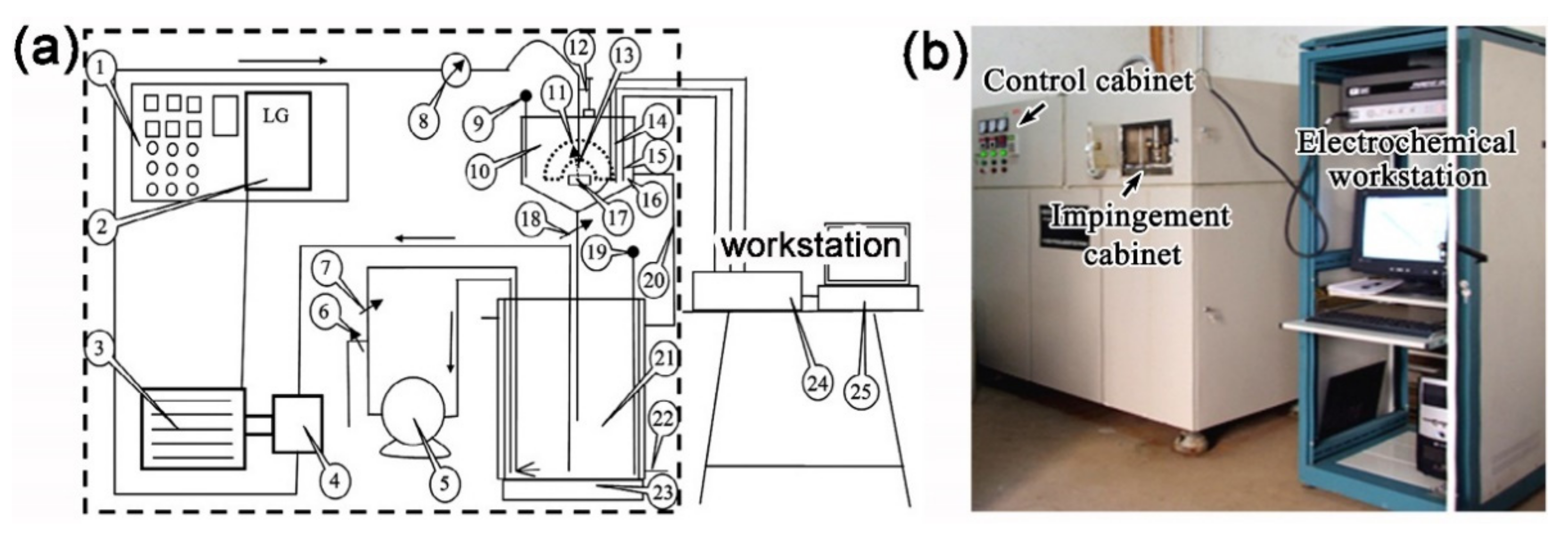
In situ potentiostatic polarization tests were carried out to further clarify the effect of the sealing treatment on the critical flow velocity for erosion–corrosion of Fe-based AMC; the tests were conducted by using an impingement jet apparatus, as shown in Figure 3 [32,33]. The slurry consisting of 3.5 wt.% NaCl solution and 2 wt.% sand jetted from a nozzle (3 mm in diameter), impacting on the sample surface with the impact angle of 90°, and the distance between the nozzle and sample surface was set as 5 mm. Similar to the RDE tests, the traditional three-electrode cell system was used, and the applied potential in the tests was set at 0 VSCE, at which all coatings were in the passive state [38]. The variation of flow velocity with impingement time during the impingement jet tests is shown in Figure 4.

2.3. Surface Characterization

The surface morphologies of four coatings before and after erosion–corrosion tests for different time were observed by scanning electron microscopy (SEM, FEI Inspect F) coupled with energy dispersive spectroscopy (EDS). The corresponding surface roughness before and after each erosion–corrosion test was examined by using a non-contact white-light interferometer (MicroXAM-1200).

2.4. Coating Characterization

In order to discuss the erosion–corrosion mechanism, micro-hardness along the depth of the polished cross-section of APS coating was carried out by a Vickers hardness tester (HV-1000) under the load of 300 g for 10 s. An average value of ten measurements for each position was used as the representative data. Meanwhile, the impact test with an impact resistance of 50 kg·cm was specially conducted on the tinplates painted with stearic acid, according to ISO 6272-2-2011, so that the fracture mode, brittle or ductile, can be recognized.

3. Results and Discussion

3.1. Surface Morphology

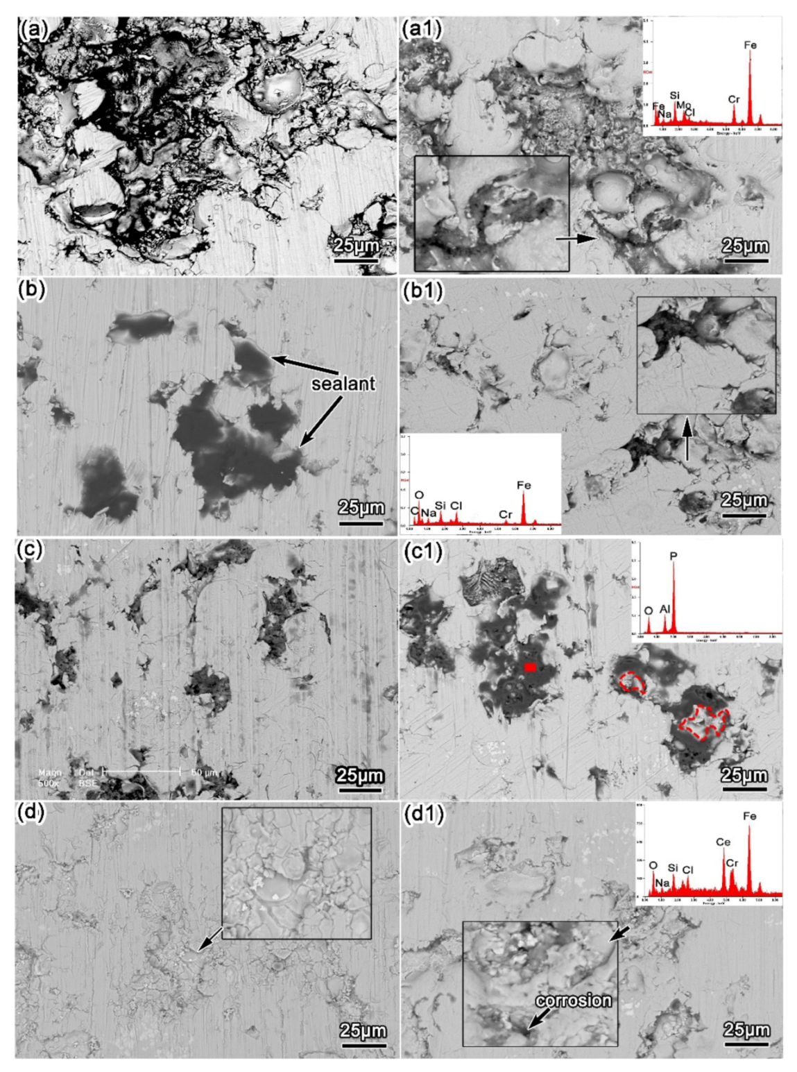
Figure 5 depicts the surface morphologies of the as-sprayed and sealed coatings before and after erosion–corrosion tests for 12 h. As seen in Figure 5a, there are some pores observed on the surface of the as-sprayed AMC. After sealing treatments, the coating surfaces become quite different. As for the SAS coating, the pores are well filled with stearic acid sealant, and the sealed layer inside the pores is smooth (Figure 5b). Although the pores of the coating treated by aluminum phosphate are also full of sealant, the sealed layer inside the pores looks similar to a honeycomb [9], as displayed in Figure 5c. In addition, the morphology of “dry-mud” appears on the CSS coating surface (Figure 5d), and it has been confirmed to be the cerium compound [39,40]. The presence of sealants inside the pores indicates that the porosity of coatings after three sealing treatments were reduced.
By comparing the surface morphologies of four coatings before and after erosion–corrosion tests, it can be found that corrosion products form on the as-sprayed AMC surface, indicating that corrosive media have penetrated to the coating/substrate interface [5,41], and the substrate beneath the coating is consequently corroded (Figure 5(a1)). Similar phenomena can be observed in the SAS coating (Figure 5(b1)) and CSS coating (Figure 5(d1)). On their surfaces, most of the sealants are removed after erosion–corrosion, and corrosion products are also detected. It is noticed that stearic acid exhibits good impermeability and hydrophobicity under static condition [17], but a large amount of this sealant is peeled off under erosion–corrosion. By contrast, the surface morphology of APS coating does not change significantly before and after erosion–corrosion tests for 12 h, and only a small amount of sealant is removed by the mechanical impact of sand, as indicated by the red-line zones in Figure 5(c1). As described above, resistance to the removal of sealants for three sealed coatings during erosion–corrosion is decreased in the order of APS coating, SAS coating and/or CSS coating. Consequently, the three sealing treatments have different effects on the erosion–corrosion of the as-sprayed AMC, as is proved later in the paper.

3.2. Three-Dimensional Roughness

The surface roughness of the as-sprayed and sealed coatings before and after erosion–corrosion tests for 12 h is visualized by three-dimensional roughness images, as presented in Figure 6. It is clear that the coating itself presents a light yellow color, whereas the pores in the coating appear to be yellowish-brown color. The darker the color, the deeper the pore; the greater the number of areas with a dark color, the higher the coating porosity. As seen in Figure 6a, the as-sprayed AMC surface is non-uniform, including a big pore and some relatively small pores, and thus is in good agreement with the surface morphology (Figure 5a). After stearic acid (Figure 6b) and aluminum phosphate (Figure 6c) sealing treatments, the fluctuations of the coating surface roughness are significantly alleviated, judged by the change of color. It indicates that the pores on the surface of the as-sprayed AMC are filled with the sealants of stearic acid or aluminum phosphate, leading to the reduction of roughness. On the contrary, the shrinkage of cerium salt during curing results in a “dry-mud” morphology (Figure 5d), making it difficult to fill the big pores. As a result, some pores are still identified, although the coating porosity is decreased to some extent (Figure 5d and Figure 6d). After exposure to the slurry for 12 h, the variations of surface roughness for the as-sprayed AMC (Figure 6(a,a1)), SAS coating (Figure 6(b,b1)) and CSS coating (Figure 6(d,d1)) are relatively noticeable, as compared to APS coating (Figure 6(c,c1)). It indicates that APS coating can resist the impact of sand particles to a certain extent and show the best erosion–corrosion resistance, as is consistent with the SEM results (Figure 5).

3.3. EIS Tests

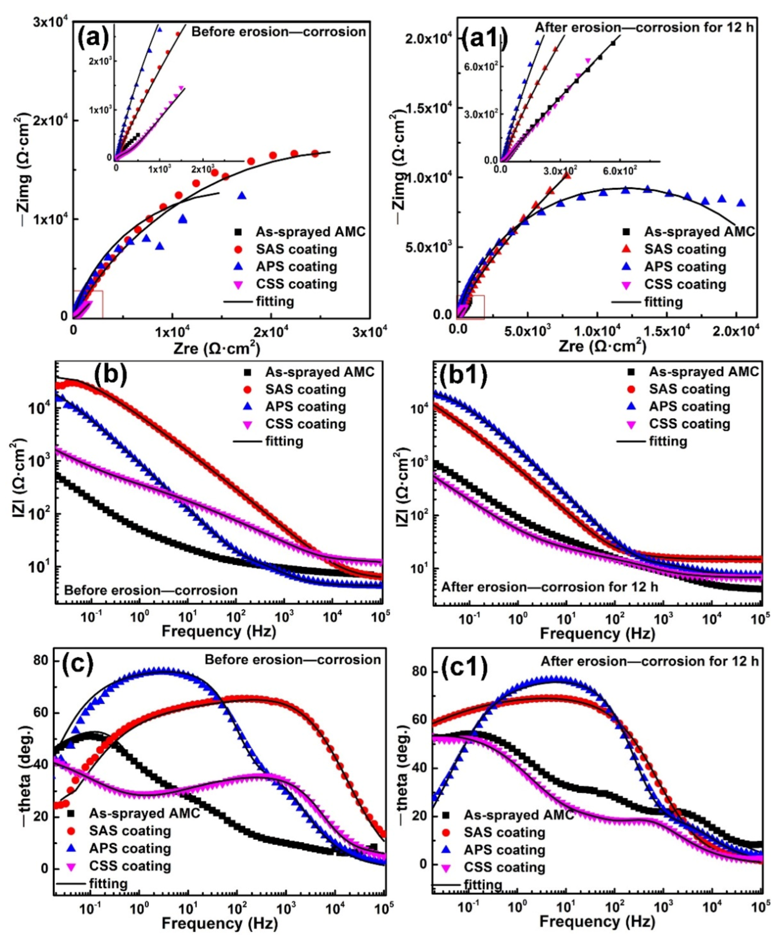
Figure 7 shows the EIS plots of the as-sprayed and sealed coatings before and after erosion–corrosion tests for 12 h. As illustrated in Figure 7, both the radius of the capacitance arc (Figure 7a) and the impedance values at 0.01 Hz (Figure 7b) for three sealed coatings were increased after the sealing treatments, indicating the improvement of corrosion resistance [42,43]. Such an improvement can be attributed to the reduction of the coating porosity induced by the sealing treatment, since pores in the coating usually act as the initiation sites for corrosion [11,41]. After erosion–corrosion for 12 h, the radius of the capacitance arc (Figure 7(a1)) and impedance values at 0.01 Hz (Figure 7(b1)) for the SAS and APS coatings were reduced, but they were still higher than those of the as-sprayed AMC. Meanwhile, the difference in the Nyquist plots between the CSS coating and the as-sprayed AMC is less noticeable. The evolution of phase angle plots is also changed in comparison with that in the static condition, except for the APS coating (Figure 7(c,c1)).
As seen in Figure 7, the as-sprayed AMC exhibits three time constants during the whole exposure period of slurry erosion, so the equivalent circuit A is employed (Figure 8a). In this model, Rs is the solution resistance, Rout and Qout are the resistance and capacitance of the outer porous layer, Rin and Qin are the resistance and capacitance of the inner layer with relatively low porosity, and Rct and Qdl are the charge transfer resistance and the capacitance of double-layer between the interface of coating and substrate. In the case of APS coating, although a small amount of sealant is peeled off from the coating surface after erosion–corrosion for 12 h, the residual sealant would continue to act as a barrier layer against erosion–corrosion. Therefore, the equivalent circuit B (Figure 8b), with two time constants, is more suitable for fitting the EIS spectra of APS coating before and after erosion–corrosion for different time. Two Rout/Qout and Rin/Qin components represent the outer and inner layer resistance and capacitance of this sealed coating, respectively. Similarly, equivalent circuit B is used to fit the EIS plots of SAS coating in the initial stage of erosion–corrosion (0–3 h). However, it is no longer suitable as the erosion–corrosion test exceeds 3 h. In these cases, equivalent circuit A with three time constants is used instead of equivalent circuit B. Compared with the other two sealed coatings, the “dry-mud” sealed layer formed on the Fe-based AMC (CSS coating) surface could decrease the diffusion rate of corrosive media into the coating, but at the same time, the corrosive media can infiltrate into the coating along the cracks. Therefore, equivalent circuit A, with three time constants, is more suitable for fitting the EIS plots of CSS coating. The fitting results show that the chi-squares of all fittings are small, demonstrating good fitting quality and reliable fitted parameters [44].
The variations of coating resistance Rcoat (Rcoat = Rout + Rin) after erosion–corrosion are used to quantitatively evaluate the erosion–corrosion resistance of four coatings, as displayed in Figure 9. The Rcoat values of APS coating tend to be relatively stable during the entire erosion–corrosion tests, and this results from the better shielding effect of the sealed layer. As shown in Figure 5(c,c1), the pore defects, even some inner pores of the APS coating, are sealed with aluminum phosphate [9,10,12], so the compact outer layer and/or inner layer can impede corrosive media penetration and sand particle impacting. Moreover, it is apparent that the APS coating shows high Rcoat values as compared to the other three coatings, especially after long erosion–corrosion tests. The corrosion resistance of the SAS coating is better than that of the APS coating under static condition (Figure 7b), but the Rcoat values decrease significantly after erosion–corrosion (Figure 9), indicating a reduction in erosion–corrosion performance. For the CSS coating, the Rcoat values are higher than those of the as-sprayed AMC within the first 1.5 h of erosion–corrosion. With erosion–corrosion tests over 1.5 h, the fluctuations of Rcoat values are almost the same as those of the as-sprayed AMC. It means that the cerium salt sealant is completely peeled off, and CSS coating has lost its inhibitory effect on erosion–corrosion. In conclusion, the APS coating exhibits the highest resistance to erosion–corrosion, followed by the SAS and CSS coatings. This is in good agreement with the results of the surface analysis.

3.4. Critical Flow Velocity

It has been proved by Zheng et al. [3] and Yi et al. [31] that the critical flow velocity for erosion–corrosion is an effective parameter to evaluate the erosion–corrosion resistance of passive materials. In order to further investigate the effect of aluminum phosphate sealing treatment on the erosion–corrosion of Fe-based AMC, the critical flow velocity of APS coating was carried out by in situ potentiostatic polarization tests, using an impingement jet apparatus. Figure 10 shows the variations of current density for the as-sprayed and APS coatings with the flow velocity. At first, the fluctuations of current density for the as-sprayed AMC keep within a low amplitude. However, as the flow velocity exceeded 11 m/s, the current density increased rapidly and then kept on rising with the flow velocity. In general, the flow velocity at which the current density starts to increase sharply can be defined as the critical flow velocity [45]. Accordingly, the critical flow velocity for the as-sprayed AMC is 11 m/s. For the APS coating, the current density is almost constant when the flow velocity is below 13 m/s. Taking the same criterion, the critical flow velocity for the APS coating can be determined as 13 m/s. Zheng et al. [3,13,45] showed that a higher critical flow velocity corresponded to the better erosion–corrosion performance of passive materials. Therefore, it can be concluded that the erosion–corrosion resistance of APS coating is superior to that of the as-sprayed AMC. It demonstrates that a suitable sealing treatment can improve the erosion–corrosion resistance of Fe-based AMC.

4. Discussion

Three sealants were chosen to seal the Fe-based AMC in this study. In the process of sealing treatments, the Fe-based AMC acts as the “substrate” to be sealed. The structure and composition of this “substrate” for the three sealed coatings are nearly the same, so the differences in erosion–corrosion performance are mainly caused by the sealing effect and the nature of sealants themselves. The sealing effect dominates the shielding performance of the coatings against the penetration of corrosive media, while the nature of the sealants determines their resistance against the mechanical impact of sand. Accordingly, the erosion–corrosion mechanisms of the sealed coatings are discussed from the aforementioned two aspects.
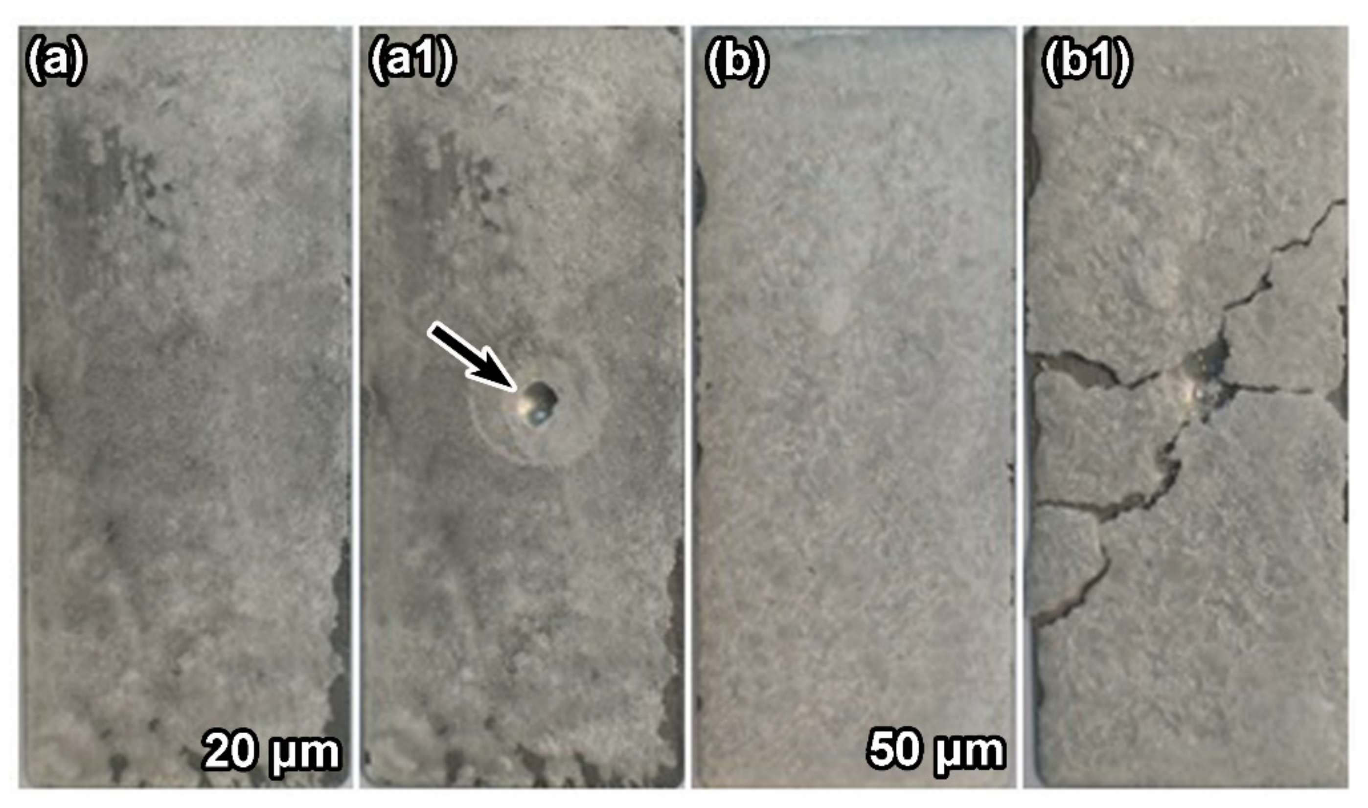
As shown in Figure 5b, Figure 6b and Figure 7, the SAS coating had the best sealing effect and the best corrosion resistance before the erosion–corrosion tests. A related study has also pointed out that stearic acid–sealed AMC displayed superior corrosion resistance compared to potassium dichromate–sealed AMC and nickel acetate–sealed AMC [17]. The results in this case are associated with the good impermeability and hydrophobicity of the stearic acid–sealed layer [14,15,16]. However, the results of the SEM (Figure 5(b1)) and surface roughness (Figure 6(b1)) show that a large amount of stearic acid sealant fell off after erosion–corrosion for 12 h. In order to further prove that stearic acid easily falls off under erosion–corrosion, the impact test was carried out on the stearic acid–coated tinplate, as shown in Figure 11. As seen in Figure 11(a,a1), the sealant at the impact point is completely broken when the thickness of the stearic acid film is around 20 μm, and severe cracking and exfoliation are observed on the sealed film’s surface when the sealed film is relatively thick, with a thickness around 50 μm (Figure 11(b,b1)). Researchers found that transverse or radioactive cracks would be formed on the surface of brittle material to absorb the energy brought by particle impacting [32,46]. Therefore, it can be reasonably deduced that the stearic acid sealant is brittle, and it is prone to be removed under erosion–corrosion. As a result, the deteriorated sealing effect weakens the erosion–corrosion performance of SAS coating (Figure 9). Moreover, it should be noted that, even though stearic acid falls off under the impact of sand, the presence of residual sealant inside the pores still plays a certain role in hindering the ingress of corrosive media. EDS mapping shown in Figure 12 confirms the existence of residual stearic acid, and the electrochemical test (Figure 7 and Figure 9) confirms that the erosion–corrosion resistance of the SAS coating is better than that of the as-sprayed AMC during erosion–corrosion.
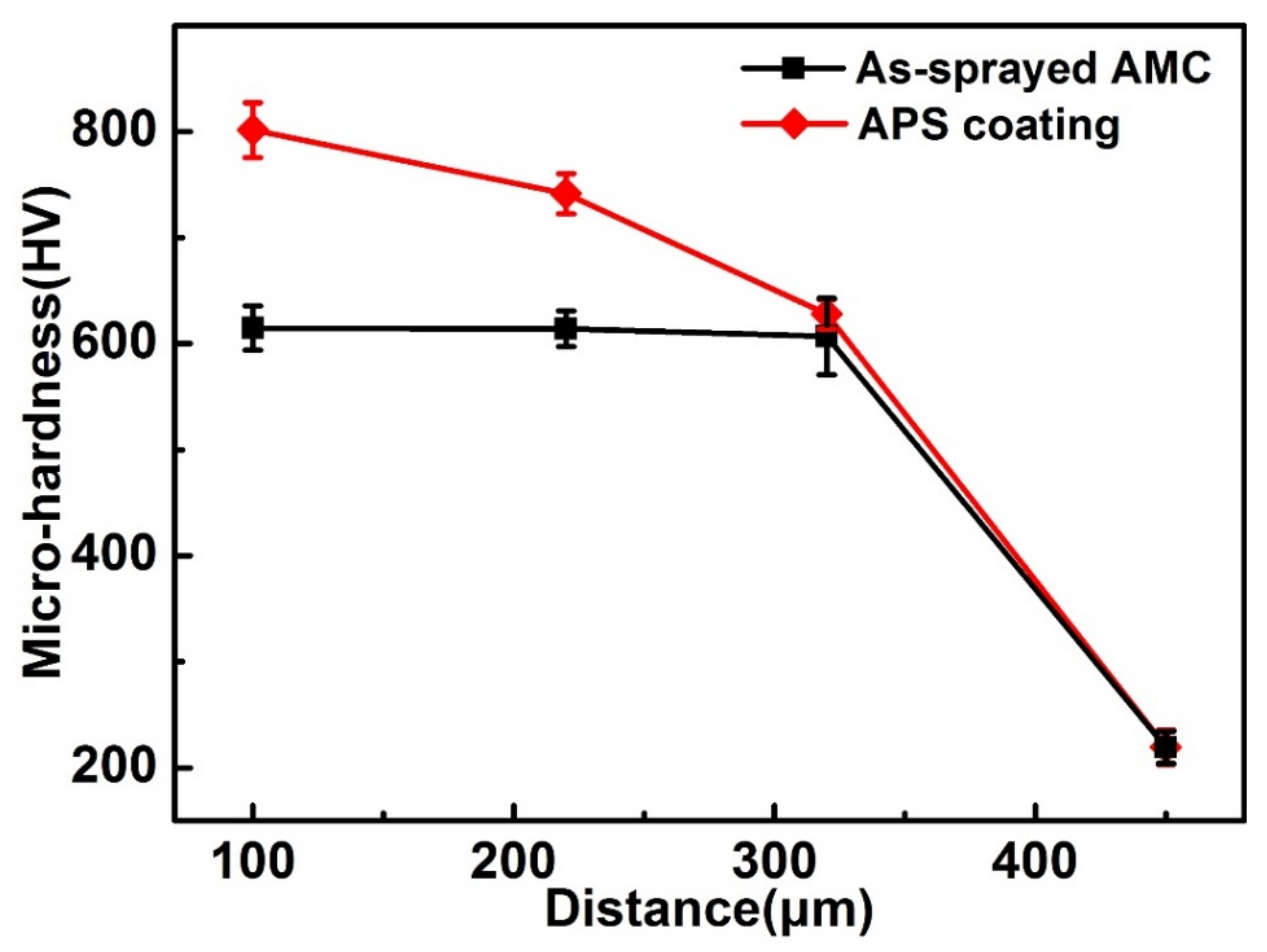
For the aluminum phosphate sealing treatment (APS coating), a series of reactions between aluminum hydroxide and phosphoric acid at different temperatures occur to form the honeycomb-like aluminum phosphate sealant, accumulating in the coating defects [9,34,35,36], as shown in Figure 5c. As a result, the corrosion resistance of the APS coating is better than that of the as-sprayed AMC, but inferior to that of the SAS coating under static condition (Figure 7). In general, sealants are susceptible to flaking off by sand impacting, as compared to Fe-based AMC, which has high hardness. However, the micro-hardness of the sealed layer is also a key factor. Figure 13 presents the micro-hardness of APS coating along the cross-section from the near-surface of this coating to the substrate. The micro-hardness of the sealed coating is around 800 HV0.3, whereas the micro-hardness of the as-sprayed AMC is about 620 HV0.3. The coating porosity has a negative role in the micro-hardness of the coatings [4]. The micro-hardness of the as-sprayed AMC with high porosity is relatively low compared with that reported in References [2,46]. However, the micro-hardness of the coating is improved by aluminum phosphate sealing treatment. It has been reported that the micro-hardness affects the erosion–corrosion of the coating [2,4,47,48,49]. The high micro-hardness of the aluminum phosphate–sealed layer can resist the impact of sand particles to some extent. There is only a small amount of aluminum phosphate peeled off after erosion–corrosion for 12 h, as indicated by the red-line zones in Figure 5(c1).
In most cases, it is difficult for the sealant to diffuse in the narrow and winding paths of the as-sprayed AMC. However, in this study, aluminum phosphate with a low viscosity can penetrate into the inner pores of the coating with the aid of ultrasonic energy [9,50,51]. Ultrasonic excitation decreases the opposite resistance caused by the air inside the coating defects and reduces the viscosity of the aluminum phosphate by providing some low-intensity cavitation. It promotes greater penetration of the sealant into the micro-pores and micro-cracks of the coating. The deep penetration of aluminum phosphate blocks the diffusion pathways of corrosive media [9,50], and the reduction in coating porosity also leads to the increase of coating hardness [7,10,52,53]. There were no corrosion products observed on the surface of the APS coating after erosion–corrosion, as presented in Figure 5(c1). This suggests that the diffusion pathways are still blocked by aluminum phosphate. The transport of corrosive media is restricted at a low diffusion rate, which results in the highest Rcoat values during erosion–corrosion (0.5–12 h). In a word, it can be concluded that both the high micro-hardness and blocking effects of the aluminum phosphate sealing treatment could be responsible for the superior erosion–corrosion resistance of the APS coating.
The cerium salt sealing treatment is based on a two-step process of dissolution and precipitation [21,24,54,55]. The occurrence of anodic and cathodic reactions during cerium salt sealing leads to the precipitation of Ce(OH)3 on the as-sprayed AMC surface [10]. As shown in Figure 5d, a sealed layer with a dry-mud appearance is covered on the coating’s surface; that is, the transport channel of corrosive media is not completely closed. The corrosive media could penetrate into the coating through the cracks of the sealed layer and parts of unsealed pores at the beginning. As a consequence, the corrosion resistance of the CSS coating is worse than that of the other sealed coatings (Figure 7). During erosion–corrosion, the mechanical impact of sand leads to the removal of the surface sealed layer (Figure 5(d1)). The re-exposed pores provide the diffusion pathways for corrosive media penetration through the coating; meanwhile, the erosion would accelerate the diffusion rate of corrosive media into the coating. The resulting Rcoat values of the CSS coating are, therefore, as low as those of the as-sprayed AMC after 1.5 h of erosion–corrosion (Figure 9), and corrosion products are observed on the coating surface (Figure 5(d1)).
Based on the analyses above, it can be confirmed that the APS coating presents a superior erosion–corrosion performance as compared to the other three coatings, and this sealant could be a good choice for porous coating applications in sand-containing seawater. In contrast, SAS coating exhibited the best corrosion resistance among the four coatings only under static condition; therefore, it could be recommended for sealing porous coatings that serve in static conditions. The cerium salt–sealed layer can be easily removed by the impact of sand, so the CSS coating exhibits the worst erosion–corrosion performance.

5. Conclusions

The pore defects and surface roughness of Fe-based AMC were reduced after sealing treatments. The SAS coating showed the best corrosion resistance under static condition, followed by the APS coating, CSS coating and the as-sprayed AMC. Most of the sealants on the SAS coating and CSS coating surfaces under erosion–corrosion peeled off, while only a small amount of aluminum phosphate was removed. Therefore, the APS coating exhibited the best erosion–corrosion performance, which is due to the combination of the deep penetration of the sealant and the high hardness of the sealed layer. Moreover, the critical flow velocity of the Fe-based AMC after the aluminum phosphate sealing treatment was increased from 11 to 13 m/s.

Author Contributions

M.L., methodology, formal analysis, investigation, conceptualization and writing—original draft; Z.W., conceptualization, methodology and writing—review and editing; H.H., conceptualization, methodology and writing—review and editing; L.Z., writing—review and editing; Y.Z., supervision and writing—review and editing. All authors have read and agreed to the published version of the manuscript.

Funding

This research was supported by China National Nuclear Corporation (CNNC) Science Fund for Talented Young Scholars.

Conflicts of Interest

The authors declare that they have no known competing financial interests or personal relationships that could have appeared to influence the work reported in this paper.

References

  1. Wang, Z.; Zheng, Y. Critical flow velocity phenomenon in erosion-corrosion of pipelines: Determination methods, mechanisms and applications. J. Pipeline Sci. Eng. 2021, 1, 63–73. [Google Scholar] [CrossRef]
  2. Wang, Y.; Zheng, Y.G.; Ke, W.; Sun, W.H.; Hou, W.L.; Chang, X.C.; Wang, J.Q. Slurry erosion–corrosion behaviour of high-velocity oxy-fuel (HVOF) sprayed Fe-based amorphous metallic coatings for marine pump in sand-containing NaCl solutions. Corros. Sci. 2011, 53, 3177–3185. [Google Scholar] [CrossRef]
  3. Zheng, Z.; Zheng, Y.; Zhou, X.; He, S.; Sun, W.; Wang, J. Determination of the critical flow velocities for erosion–corrosion of passive materials under impingement by NaCl solution containing sand. Corros. Sci. 2014, 88, 187–196. [Google Scholar] [CrossRef]
  4. Wang, Y.; Jiang, S.L.; Zheng, Y.G.; Ke, W.; Sun, W.H.; Chang, X.C.; Hou, W.L.; Wang, J.Q. Effect of processing parameters on the microstructures and corrosion behaviour of high-velocity oxy-fuel (HVOF) sprayed Fe-based amorphous metallic coatings. Mater. Corros. 2013, 64, 801–810. [Google Scholar] [CrossRef]
  5. Zhang, S.; Zhang, W.; Wang, S.; Gu, X.; Wang, J. Characterisation of three-dimensional porosity in an Fe-based amorphous coating and its correlation with corrosion behaviour. Corros. Sci. 2015, 93, 211–221. [Google Scholar] [CrossRef]
  6. Shin, D.; Hamed, A. Influence of micro–structure on erosion resistance of plasma sprayed 7YSZ thermal barrier coating under gas turbine operating conditions. Wear 2018, 396–397, 34–47. [Google Scholar] [CrossRef]
  7. Farmer, J.; Wong, F.; Haslam, J.; Estill, J.; Branagan, D.; Yang, N.; Blue, C. Development, processing and testing of high-performance corrosion-resistant HVOF coatings. In Proceedings of the Global 2003 Topical Meeting at the American Nuclear Society Conference, New Orleans, LA, USA, 16–20 November 2003; pp. 1–6. [Google Scholar]
  8. Liu, M.; Hu, H.; Zheng, Y.; Wang, J.; Gan, Z.; Qiu, S. Effect of sol-gel sealing treatment loaded with different cerium salts on the corrosion resistance of Fe-based amorphous coating. Surf. Coat. Technol. 2019, 367, 311–326. [Google Scholar] [CrossRef]
  9. Liu, M.; Hu, H.; Zheng, Y. Effects of three sealing methods of aluminum phosphate sealant on corrosion resistance of the Fe-based amorphous coating. Surf. Coat. Technol. 2017, 309, 579–589. [Google Scholar] [CrossRef]
  10. Wang, Y.; Jiang, S.; Zheng, Y.; Ke, W.; Sun, W.; Wang, J. Effect of porosity sealing treatments on the corrosion resistance of high-velocity oxy-fuel (HVOF)-sprayed Fe-based amorphous metallic coatings. Surf. Coat. Technol. 2011, 206, 1307–1318. [Google Scholar] [CrossRef]
  11. Wu, J.; Zhang, S.; Sun, W.; Gao, Y.; Wang, J. Enhanced corrosion resistance in Fe-based amorphous coatings through eliminating Cr-depleted zones. Corros. Sci. 2018, 136, 161–173. [Google Scholar] [CrossRef]
  12. Wu, J.; Zhang, S.; Sun, W.; Wang, J. Influence of oxidation related structural defects on localized corrosion in HVAF-sprayed Fe-based metallic coatings. Surf. Coat. Technol. 2018, 335, 205–218. [Google Scholar] [CrossRef]
  13. Zheng, Z.; Zheng, Y. Effects of surface treatments on the corrosion and erosion-corrosion of 304 stainless steel in 3.5% NaCl solution. Corros. Sci. 2016, 112, 657–668. [Google Scholar] [CrossRef]
  14. Arun, S.; Sooraj, P.; Hariprasad, S.; Arunnellaiappan, T.; Rameshbabu, N. Fabrication of superhydrophobic coating on PEO treated zirconium samples and its corrosion resistance. Mater. Today Proc. 2020, 27, 2056–2060. [Google Scholar] [CrossRef]
  15. Cui, X.J.; Lin, X.Z.; Liu, C.H.; Yang, R.S.; Zheng, X.W.; Gong, M. Fabrication and corrosion resistance of a hydrophobic micro-arc oxidation coating on AZ31 Mg alloy. Corros. Sci. 2015, 90, 402–412. [Google Scholar] [CrossRef]
  16. Zuo, Y.; Zhao, P.H.; Zhao, J.M. The influences of sealing methods on corrosion behavior of anodized aluminum alloys in NaCl solutions. Surf. Coat. Technol. 2003, 166, 237–242. [Google Scholar] [CrossRef]
  17. Zhang, L.; Zhang, S.; Ma, A.; Hu, H.; Zheng, Y.; Yang, B.; Wang, J. Influence of sealing treatment on the corrosion behavior of HVAF sprayed Al-based amorphous/nanocrystalline coating. Surf. Coat. Technol. 2018, 353, 263–273. [Google Scholar] [CrossRef]
  18. Shao, F.; Yang, K.; Zhao, H.; Liu, C.; Wang, L.; Tao, S. Effects of inorganic sealant and brief heat treatments on corrosion behavior of plasma sprayed Cr2O3–Al2O3 composite ceramic coatings. Surf. Coat. Technol. 2015, 276, 8–15. [Google Scholar] [CrossRef]
  19. Knuuttila, J.; Ahmaniemi, S.; Mäntylä, T. Wet abrasion and slurry erosion resistance of thermally sprayed oxide coatings. Wear 1999, 232, 207–212. [Google Scholar] [CrossRef]
  20. Leivo, E.M.; Vippola, M.S.; Sorsa, P.; Vuoristo, P.; Mntyl, T.A. Wear and corrosion properties of plasma sprayed Al2O3 and Cr2O3 coatings sealed by aluminum phosphates. J. Therm. Spray. Technol. 1997, 6, 205–210. [Google Scholar] [CrossRef]
  21. Mingo, B.; Arrabal, R.; Mohedano, M.; Llamazares, Y.; Matykina, E.; Yerokhin, A.; Pardo, A. Influence of sealing post-treatments on the corrosion resistance of PEO coated AZ91 magnesium alloy. Appl. Surf. Sci. 2018, 433, 653–667. [Google Scholar] [CrossRef]
  22. Van Phuong, N.; Fazal, B.R.; Moon, S. Cerium- and phosphate-based sealing treatments of PEO coated AZ31 Mg alloy. Surf. Coat. Technol. 2017, 309, 86–95. [Google Scholar] [CrossRef]
  23. Dong, Q.; Ba, Z.; Jia, Y.; Chen, Y.; Lv, X.; Zhang, X.; Wang, Z. Effect of solution concentration on sealing treatment of Mg-Al hydrotalcite film on AZ91D Mg alloy. J. Magnes. Alloy. 2017, 5, 320–325. [Google Scholar] [CrossRef]
  24. Wang, X.; Zhu, L.; He, X.; Sun, F. Effect of cerium additive on aluminum-based chemical conversion coating on AZ91D magnesium alloy. Appl. Surf. Sci. 2013, 280, 467–473. [Google Scholar] [CrossRef]
  25. Yu, X.W.; Yan, C.W.; Cao, C.A. Study on the rare earth sealing procedure of the porous film of anodized 2024 aluminum alloy. J. Mater. Sci. Technol. 2003, 19, 51–53. [Google Scholar]
  26. Toor, I.U.; Alashwan, Z.; Badr, H.M.; Ben-Mansour, R.; Shirazi, S.A. Effect of Jet Impingement Velocity and Angle on CO2 Erosion–Corrosion with and without Sand for API 5L-X65 Carbon Steel. Materials 2020, 13, 2198. [Google Scholar] [CrossRef]
  27. Yi, J.; Hu, H.; Wang, Z.; Zheng, Y. On the critical flow velocity for erosion-corrosion of Ni-based alloys in a saline-sand solution. Wear 2020, 458–459, 203417. [Google Scholar] [CrossRef]
  28. Ismail, A.; Irshad, H.M.; Zeino, A.; Toor, I.H. Electrochemical Corrosion Performance of Aromatic Functionalized Imidazole Inhibitor under Hydrodynamic Conditions on API X65 Carbon Steel in 1 M HCl Solution. Arab. J. Sci. Eng. 2019, 44, 5877–5888. [Google Scholar] [CrossRef]
  29. Hu, H.X.; Guo, X.M.; Zheng, Y.G. Comparison of the cavitation erosion and slurry erosion behavior of cobalt-based and nickel-based coatings. Wear 2019, 428–429, 246–257. [Google Scholar] [CrossRef]
  30. Toor, I.U.; Irshad, H.M.; Badr, H.M.; Samad, M.A. The Effect of Impingement Velocity and Angle Variation on the Erosion Corrosion Performance of API 5L-X65 Carbon Steel in a Flow Loop. Metals 2018, 8, 402. [Google Scholar] [CrossRef] [Green Version]
  31. Yi, J.; Hu, H.; Wang, Z.; Zheng, Y. Comparison of critical flow velocity for erosion-corrosion of six stainless steels in 3.5 wt% NaCl solution containing 2 wt% silica sand particles. Wear 2018, 416–417, 62–71. [Google Scholar] [CrossRef]
  32. Zheng, Z.; Zheng, Y.; Sun, W.; Wang, J. Erosion–corrosion of HVOF-sprayed Fe-based amorphous metallic coating under impingement by a sand-containing NaCl solution. Corros. Sci. 2013, 76, 337–347. [Google Scholar] [CrossRef]
  33. Hu, H.; Zheng, Y.; Qin, C. Comparison of Inconel 625 and Inconel 600 in resistance to cavitation erosion and jet impingement erosion. Nucl. Eng. Des. 2010, 240, 2721–2730. [Google Scholar] [CrossRef]
  34. Vippola, M.; Ahmaniemi, S.; Keränen, J.; Vuoristo, P.; Lepistö, T.; Mäntylä, T.; Olsson, E. Aluminum phosphate sealed alumina coating: Characterization of microstructure. Mater. Sci. Eng. A 2002, 323, 1–8. [Google Scholar] [CrossRef]
  35. Ahmaniemi, S.; Vippola, M.; Vuoristo, P.; Mäntylä, T.; Buchmann, M.; Gadow, R. Residual stresses in aluminium phosphate sealed plasma sprayed oxide coatings and their effect on abrasive wear. Wear 2002, 252, 614–623. [Google Scholar] [CrossRef]
  36. Morris, J.H.; Perkins, P.G.; Rose, A.E.A.; Smith, W.E. The chemistry and binding properties of aluminium phosphates. Chem. Soc. Rev. 1977, 6, 173–194. [Google Scholar] [CrossRef]
  37. Dean, S.D. Velocity-accelerated corrosion testing and predictions. Mater. Perform. 1990, 29, 61–67. [Google Scholar]
  38. Li, L.; Wang, Z.; Zheng, Y. Interaction between pitting corrosion and critical flow velocity for erosion-corrosion of 304 stainless steel under jet slurry impingement. Corros. Sci. 2019, 158, 108084. [Google Scholar] [CrossRef]
  39. Wu, G.; Wang, C.; Zhang, Q.; Kang, P. Characterization of Ce conversion coating on Gr-f/6061Al composite surface for corrosion protection. J. Alloys Compd. 2008, 461, 389–394. [Google Scholar] [CrossRef]
  40. Pardo, A.; Merino, M.; Arrabal, R.; Merino, S.; Viejo, F.; Carboneras, M. Effect of Ce surface treatments on corrosion resistance of A3xx.x/SiCp composites in salt fog. Surf. Coat. Technol. 2006, 200, 2938–2947. [Google Scholar] [CrossRef]
  41. Zhang, S.; Wu, J.; Qi, W.; Wang, J. Effect of porosity defects on the long-term corrosion behaviour of Fe-based amorphous alloy coated mild steel. Corros. Sci. 2016, 110, 57–70. [Google Scholar] [CrossRef]
  42. Qiao, Y.; Wang, X.; Yang, L.; Wang, X.; Chen, J.; Wang, Z.; Zhou, H.; Zou, J.; Wang, F. Effect of aging treatment on microstructure and corrosion behavior of a Fe-18Cr-15Mn-0.66N stainless steel. J. Mater. Sci. Technol. 2021, 107, 197–206. [Google Scholar] [CrossRef]
  43. Tang, Y.B.; Shen, X.W.; Liu, Z.H.; Qiao, Y.X.; Yang, L.L.; Lu, D.H.; Zou, J.S.; Xu, J. Corrosion behaviors of selective laser melted inconel 718 alloy in NaOH solution. Acta Metall. Sin. 2022, 58, 324–333. [Google Scholar]
  44. Wang, Z.; Hu, H.; Zheng, Y.; Ke, W.; Qiao, Y. Comparison of the corrosion behavior of pure titanium and its alloys in fluoride-containing sulfuric acid. Corros. Sci. 2016, 103, 50–65. [Google Scholar] [CrossRef]
  45. Zheng, Z.; Zheng, Y.; Sun, W.; Wang, J. Effect of applied potential on passivation and erosion–corrosion of a Fe-based amorphous metallic coating under slurry impingement. Corros. Sci. 2014, 82, 115–124. [Google Scholar] [CrossRef]
  46. Zheng, Z.; Zheng, Y.; Sun, W.; Wang, J. Effect of heat treatment on the structure, cavitation erosion and erosion–corrosion behavior of Fe-based amorphous coatings. Tribol. Int. 2015, 90, 393–403. [Google Scholar] [CrossRef]
  47. Lu, B.; Luo, J. Correlation between surface-hardness degradation and erosion resistance of carbon steel—Effects of slurry chemistry. Tribol. Int. 2015, 83, 146–155. [Google Scholar] [CrossRef]
  48. Grewal, H.; Agrawal, A.; Singh, H. Slurry erosion performance of Ni–Al2O3 based composite coatings. Tribol. Int. 2013, 66, 296–306. [Google Scholar] [CrossRef]
  49. Divakar, M.; Agarwal, V.; Singh, S. Effect of the material surface hardness on the erosion of AISI316. Wear 2005, 259, 110–117. [Google Scholar] [CrossRef]
  50. Hong, S.; Wei, Z.; Wang, K.; Gao, W.; Wu, Y.; Lin, J. The optimization of microbial influenced corrosion resistance of HVOF sprayed nanostructured WC-10Co-4Cr coatings by ultrasound-assisted sealing. Ultrason. Sonochem. 2021, 72, 105438. [Google Scholar] [CrossRef]
  51. Si, L.Q.; Wang, Z.H.; Zhou, Z.H.; Jiang, S.Q.; Cheng, J.B.; Wang, G. Influence of Sealing Treatments with Ultrasonic Excitation on Corrosion Resistance of Plasma-sprayed Al2O3-13wt% TiO2 Coatings. Rare Met. Mat. Eng. 2012, 41, 223–227. [Google Scholar]
  52. Saaedi, J.; Coyle, T.W.; Arabi, H.; Mirdamadi, S.; Mostaghimi, J. Effects of HVOF Process Parameters on the Properties of Ni-Cr Coatings. J. Therm. Spray Technol. 2010, 19, 521–530. [Google Scholar] [CrossRef]
  53. Ice, M.; Lavernia, E. Particle Melting Behavior during High-Velocity Oxygen Fuel Thermal Spraying. J. Therm. Spray Technol. 2001, 10, 83–93. [Google Scholar] [CrossRef]
  54. Li, L.; Lei, J.; Yu, S.; Tian, Y.; Jiang, Q.; Pan, F. Formation and characterization of cerium conversion coatings on magnesium alloy. J. Rare Earths 2008, 26, 383–387. [Google Scholar] [CrossRef]
  55. Scholes, F.; Soste, C.; Hughes, A.; Hardin, S.; Curtis, P. The role of hydrogen peroxide in the deposition of cerium-based conversion coatings. Appl. Surf. Sci. 2006, 253, 1770–1780. [Google Scholar] [CrossRef]
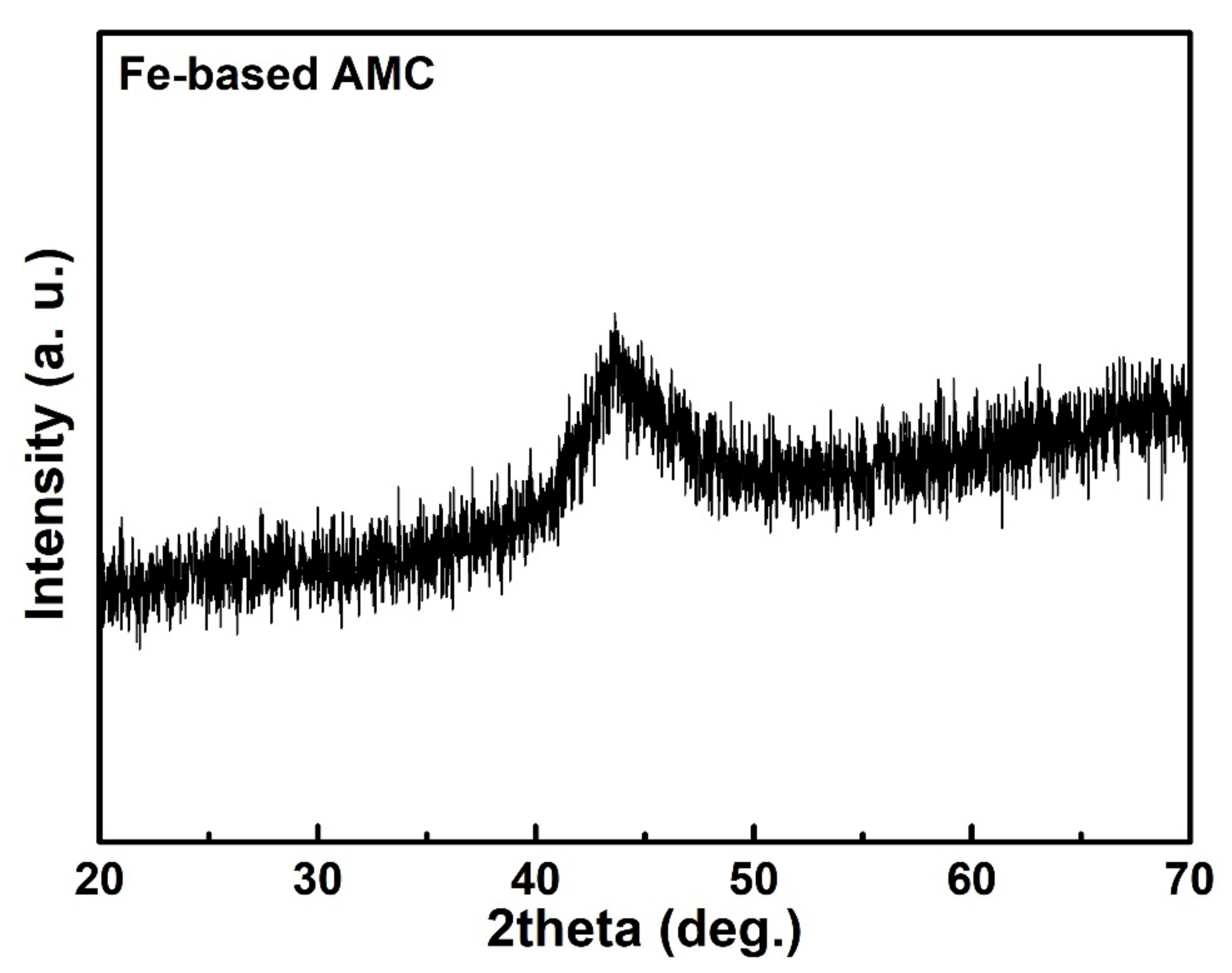
Figure 1. XRD pattern of the as-sprayed Fe-based AMC coating.
Metals 12 00680 g001
Figure 2. (a) Schematic diagram of homemade rotating disc electrode (RDE): (1) motor, (2) bolt, (3) rotating disk, (4) baffle, (5) water trough, (6) bracket of water trough, (7) jack, (8) water inlet, (9) circular cooling water, (10) water outlet and (11) cooling device. (b) Schematic diagram of rotating disk: (1) disk, (2) bolt, (3) specimen, (4) plastic mat and (5) nylon clamp. Schematic diagram of (c) specimen. (d) Digital picture of homemade RDE.
Metals 12 00680 g002
Figure 3. (a) Schematic diagram and (b) digital picture of the jet impingement apparatus for erosion–corrosion. (1) Control cabinet; (2) frequency converter; (3) motor; (4) lobular pump; (5) stirring pump; (6,7) valves; (8) screw elevator; (9) thermocouple I; (10) impingement cabinet; (11) impingement angle meter; (12) electromagnetic flowmeter; (13) nozzle; (14) reference electrode; (15) counter electrode; (16) pH meter probe; (17) sample (working electrode); (18) valve; (19) thermocouple II; (20) overflow tube; (21) slurry container; (22) cooling water; (23) heater; (24) electrochemical workstation; and (25) computer.
Metals 12 00680 g003
Figure 4. Variation of flow velocity versus impingement time.
Metals 12 00680 g004
Figure 5. SEM morphologies of (a,a1) as-sprayed AMC, (b,b1) SAS coating, (c,c1) APS coating and (d,d1) CSS coating (ad) before and (a1d1) after erosion–corrosion tests for 12 h by 3.5 wt.% NaCl solution containing 2 wt.% sand.
Metals 12 00680 g005
Figure 6. Three-dimensional surface roughness of (a,a1) as-sprayed AMC, (b,b1) SAS coating, (c,c1) APS coating and (d,d1) CSS coating (ad) before and (a1d1) after erosion–corrosion tests for 12 h by 3.5 wt.% NaCl solution containing 2 wt.% sand.
Metals 12 00680 g006
Figure 7. EIS plots of four coatings (ac) before and (a1c1) after erosion–corrosion tests for 12 h by 3.5 wt.% NaCl solution containing 2 wt.% sand. (a,a1) Nyquist plots, (b,b1) Bode impedance magnitude plots and (c,c1) Bode phase angle plots.
Metals 12 00680 g007
Figure 8. General model of the equivalent circuits used to fit the EIS data. (a) Equivalent circuit A, (b) Equivalent circuit B.
Metals 12 00680 g008
Figure 9. Variations of the resistance Rcoat for four coatings before and after erosion–corrosion for different time.
Metals 12 00680 g009
Figure 10. Records of the current density for the as-sprayed and APS coatings at 0 VSCE with increasing the flow velocity.
Metals 12 00680 g010
Figure 11. Photos of stearic acid-coated tinplate (a,b) before and (a1,b1) after the impact test: (a,a1) the sealed film with a thickness of around 20 μm, and (b,b1) the sealed film with a thickness of around 50 μm.
Metals 12 00680 g011
Figure 12. SEM micrograph and EDS elemental mapping of SAS coating surface after erosion–corrosion tests for 12 h by 3.5 wt.% NaCl solution containing 2 wt.% sand.
Metals 12 00680 g012
Figure 13. Micro-hardness of APS coating along the cross-section from the near-surface of this coating to the substrate.
Metals 12 00680 g013
Publisher’s Note: MDPI stays neutral with regard to jurisdictional claims in published maps and institutional affiliations.