Article

Cast Austenitic Stainless Steel Reinforced with WC Fabricated by Ex Situ Technique

by
Aida B. Moreira
1,2,
Laura M. M. Ribeiro
1,2 and
Manuel F. Vieira
1,2,*
1
Department of Metallurgical and Materials Engineering, Faculty of Engineering, University of Porto, R. Dr. Roberto Frias, 4200-465 Porto, Portugal
2
LAETA/INEGI—Institute of Science and Innovation in Mechanical and Industrial Engineering, R. Dr. Roberto Frias, 4200-465 Porto, Portugal
*
Author to whom correspondence should be addressed.
Metals 2022, 12(5), 713; https://doi.org/10.3390/met12050713
Submission received: 14 March 2022 / Revised: 13 April 2022 / Accepted: 19 April 2022 / Published: 21 April 2022

Abstract

:
In this study, the process of reinforcing austenitic stainless steel with tungsten carbide (WC) particles prepared by an ex situ technique was investigated. More specifically, the effect of microstructural features on the properties of the resulting WC-metal matrix composite (WC-MMC) was studied. For that purpose, porous Fe-WC preforms, prepared by the ex situ technique, were fixed in the mold cavity where they reacted with the molten steel. As confirmed by scanning electron microscopy with energy dispersive spectroscopy (SEM/EDS), the resulting composite showed a compositional and microstructural gradient in depth. The microstructure next to the surface is essentially martensite with large WC particles. From this region to the base metal, the dissolution of the original WC particles increased, being closely related to the formation of new carbides: (Fe,W,Cr)6C, (Fe,Cr,W)7C3, and (Fe,Cr,W)23C6. At the interface bonding, a sound microstructure free of discontinuities was achieved. Furthermore, the mechanical tests indicated that the WC-MMC is four times harder and more wear-resistant than the base metal.

1. Introduction

Austenitic stainless steel is one of the best materials for applications in which corrosion resistance plays a key role in in-service performance. The high level of corrosion resistance in combination with other outstanding properties, such as mechanical strength, toughness, conformability, and weldability, have promoted the wide use of these materials in the marine, mining, chemical, petrochemical, nuclear, and food processing industries. For instance, specific grades can be applied in pressure-containing parts for the energy production and petrochemical industries designed to work under temperatures above 500 °C and in sulfuric acid exposure [1,2,3,4].
One limitation of the austenitic stainless steel is the low resistance to wear, being therefore replaced by martensitic stainless steel when wear performance is required [5]. One way to improve the wear resistance of austenitic stainless steel cast components is to modify the surface through a local reinforcement with hard metal matrix composites (MMCs). The main advantage of this approach is to produce parts with a complex shape and hardworking surfaces in combination with high corrosion resistance [6,7,8].
Several studies have been carried out to investigate the methodologies for producing locally reinforced steel parts with tungsten carbide (WC) particles [9,10,11,12,13,14,15,16]. More recently, austenitic stainless steel castings locally reinforced with Fe-WC inserts by employing an ex situ technique based on powder metallurgy technology were also successfully produced, and detailed microstructural characterization of phases formed in the reinforcement zone was performed [17]. This study aims to expand the knowledge about the behavior of locally reinforced stainless steel by analyzing the mechanical properties, including that of the phases formed. Therefore, the main purpose of this work is to investigate the wear behavior of austenitic stainless steel cast specimens locally reinforced with WC particles fabricated by the ex situ technique, and to understand the relationship between the hardness of the phases formed and the wear performance of the material. The microstructure was characterized by scanning electron microscopy with energy dispersive spectroscopy (SEM/EDS), and the Vickers hardness and ball-cratering microabrasion tests were used to investigate the mechanical response of the reinforced cast specimens.

2. Materials and Methods

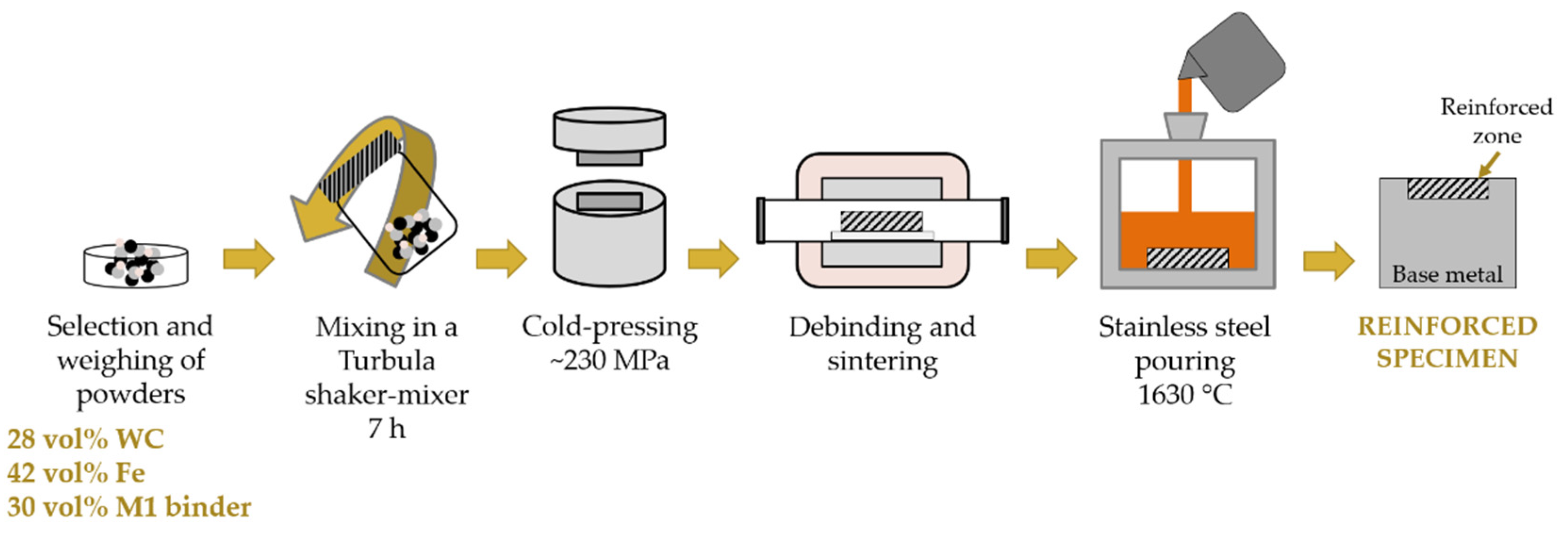
2.1. Reinforced Specimens Fabrication

The specimens were produced by casting as described in detail in our recent work [17]. Porous Fe-WC preforms, composed of 28 vol.% WC (D50 = 107 µm), 42 vol.% Fe (D50 = 8 µm), and 30 vol.% M0101 binder (D50 = 398 µm), with dimensions of 31 mm × 12 mm × 9 mm, were prepared using powder technology. The porous Fe-WC preforms were then placed in the mold cavity, and the stainless steel melt (0.06 wt% C, 0.79 wt% Si, 0.80 wt% Mn, 18.30 wt% Cr, 11.07 wt% Ni, 2.41 wt% Mo, and 0.31 wt% Cu) was poured to obtain the reinforced specimens (see Figure 1). The cast specimens were solubilized at 1075 °C for 2 h and quenched in water. This is a standard procedure to dissolve chromium carbides that may have precipitated at the grain boundaries during solidification, with a detrimental effect on the intergranular corrosion susceptibility of the austenitic stainless steel.

2.2. Microstructural Analysis

The specimens were cut by wire electrical discharge to a microstructural and mechanical analysis of the composite zone and base metal. The samples were metallographically prepared and electrolytically etched with 10% oxalic acid. A detailed characterization of the microstructure was performed by optical microscopy (OM), using a Leica DM4000 M with a DFC 420 camera (Leica Microsystems, Wetzlar, Germany), and scanning electron microscopy (SEM), using an FEI Quanta 400 FEG (FEI Company, Hillsboro, OR, USA) with an energy-dispersive detector (EDS). SEM images were taken with backscattered (BSE) and secondary (SE) electron detectors. The volume percent of the carbides in the composite zone was measured using ImageJ (V.1.52, Wayne Rasband, National Institutes of Health, Bethesda, MD, USA), an open-source image analysis software, and EDS maps with 500× magnification because the OM and BSE-SEM images did not provide proper contrast for distinguishing between carbides and the matrix.

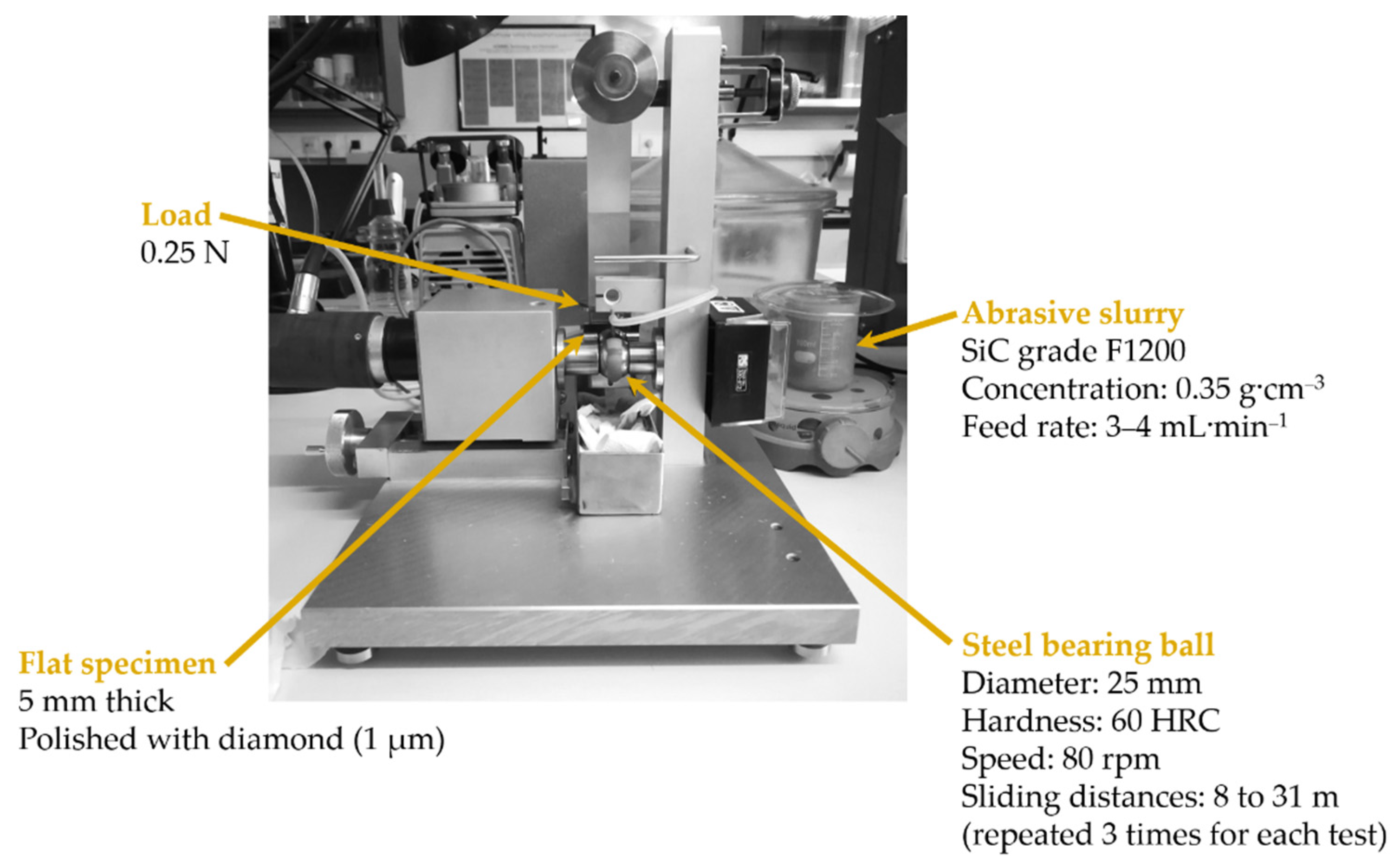
2.3. Mechanical Analysis

The mechanical characterization of the reinforced zone and the base metal was performed by hardness and ball-cratering abrasion tests. At least seven Vickers hardness indentations were carried out in each area, with a load of 294.2 N in a DuraVision 20 universal hardness test (EMCO-TEST Prüfmaschinen GmbH, Kuchl, Austria). Vickers microhardness tests were also performed in a Duramin-1 hardness tester (Struers Inc., Cleveland, OH, USA), using a load of 0.9807 N for WC and (Fe,W,Cr)6C particles, and a load of 0.0245 N for (Fe,W,Cr)3C and (Fe,Cr,W)7C3/(Fe,Cr,W)23C6 particles. The load was established according to the size of the particles and at least ten indentations were used to calculate the hardness of each phase. In addition, the variation in hardness along the reinforcement depth was characterized with a hardness profile determined with a load of 19.6 N.
The abrasion tests were performed in a Plint TE66 microscale abrasion tester (Plint & Partners Ltd., Newbury, UK) using the test conditions shown in Figure 2. For each zone, the wear test was carried out for sliding distances of 7.9, 15.7, 23.6, and 31.4 m, and the wear craters were measured by OM and image processing software (ImageJ v.1.52) and analyzed by SEM. Then, the abrasive wear rate (K, in mm3∙N−1∙mm−1) was calculated with the Archard wear equation (see Equation (1)).
K = V × 1 S × N
where V is the volume of the worn material (mm3) calculated with Equation (2), S is the sliding distance (mm), and N is the applied load (N).
V = π × b 4 64 × R
in which b is the crater mean diameter (mm) and R is the steel ball radius (mm).

3. Results

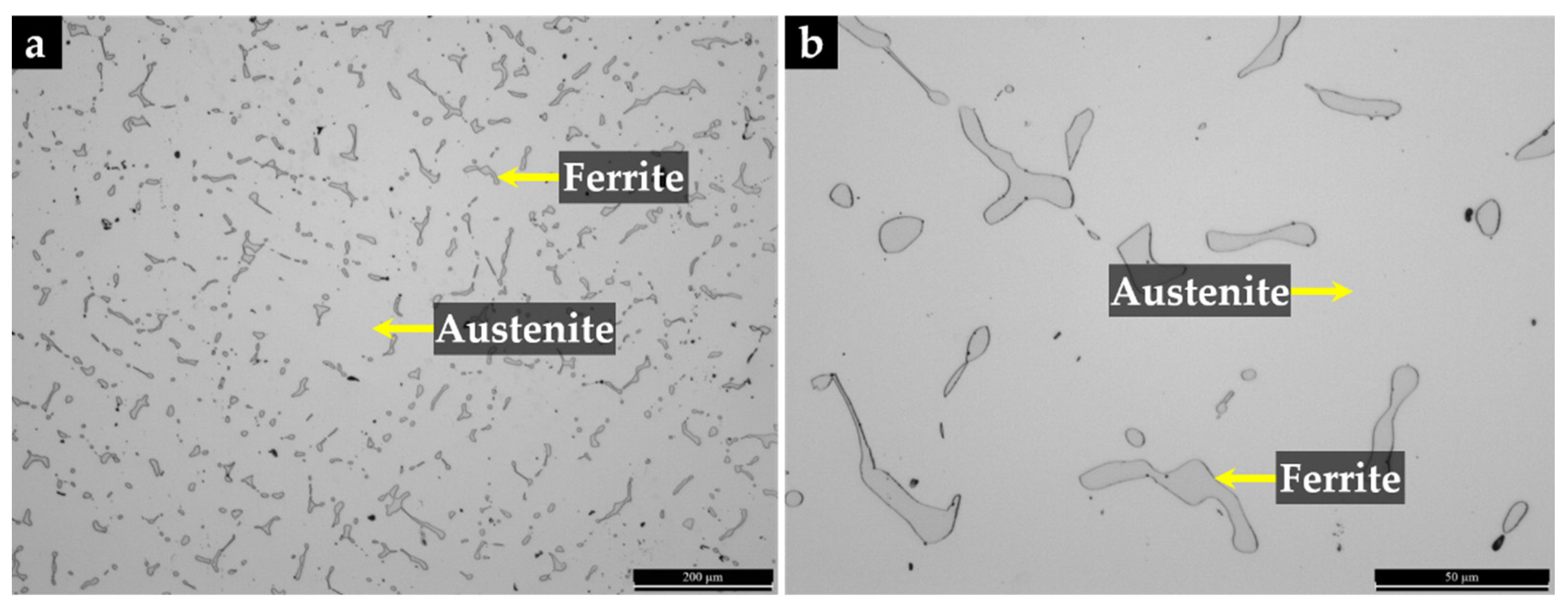
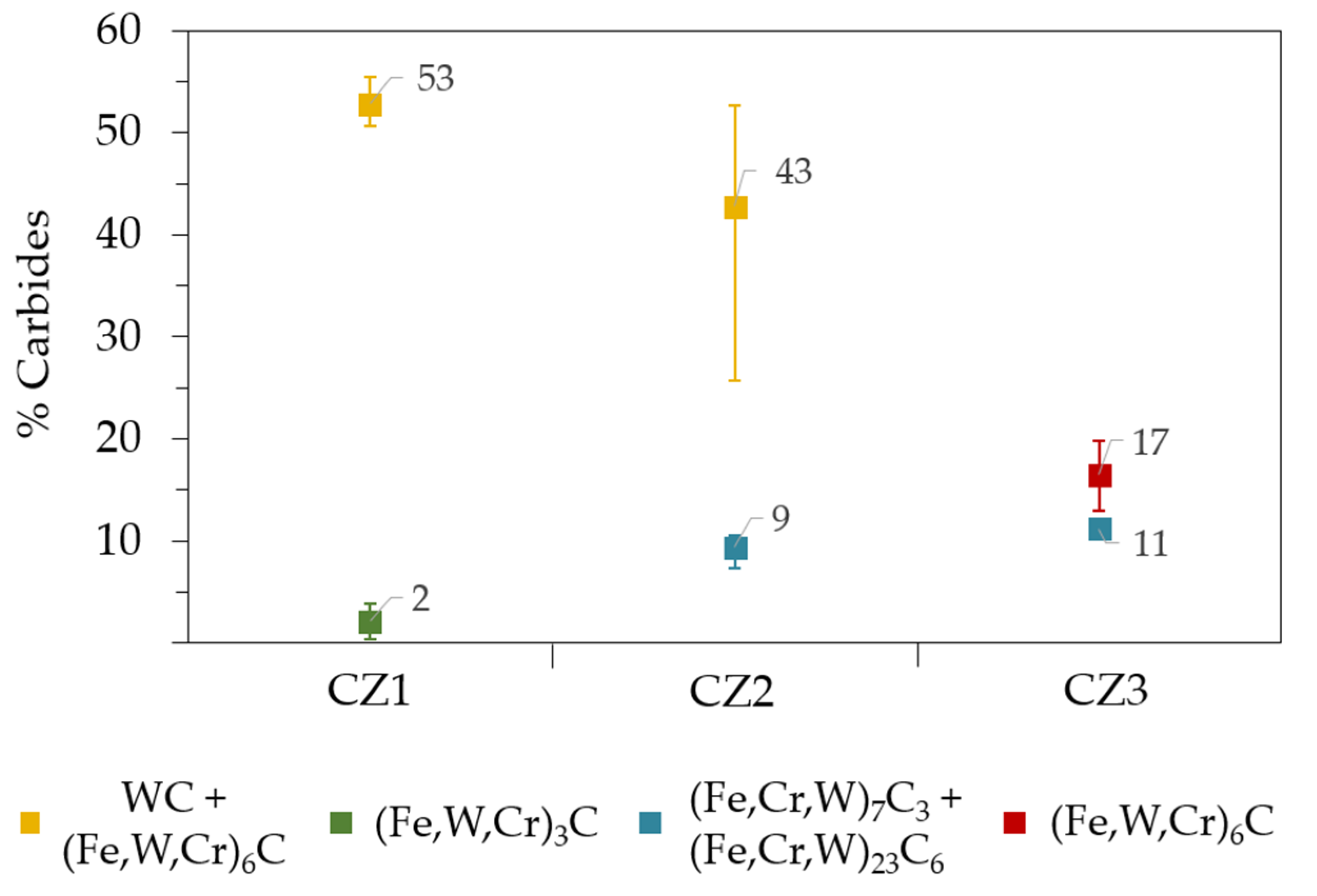
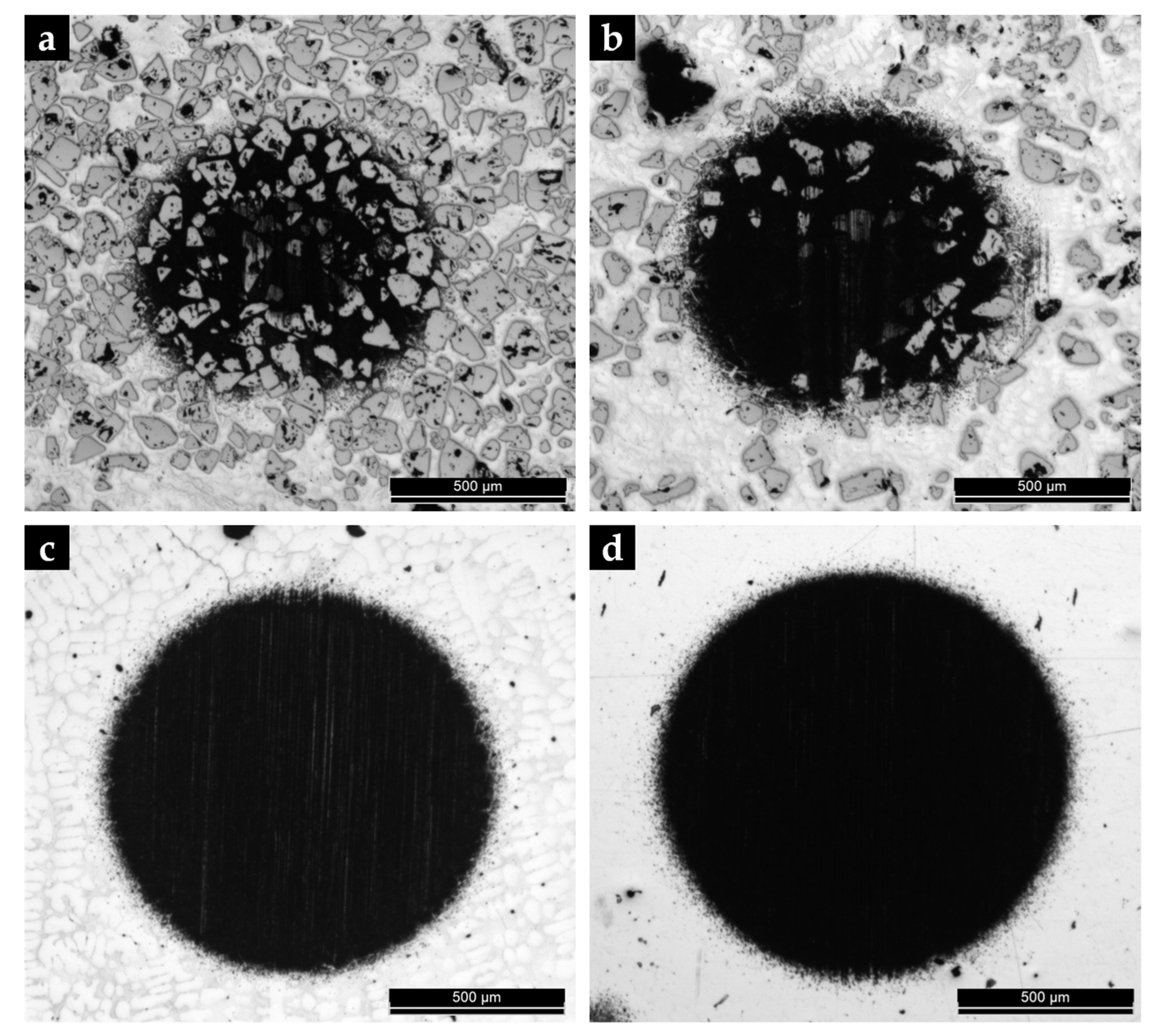
3.1. Microstructural Characterization of the Reinforced Specimens

The microstructure of the base metal after solubilization at 1075 °C for 2 h and quenching in water is shown in Figure 3. The electrolytic etching revealed small grains of ferrite in the matrix of austenite (γ). Our previous study reports in detail the characterization of these phases by SEM/EDS, electron backscatter diffraction (EBSD), and X-ray diffraction (XRD) techniques [17].
The microstructure of the reinforced zone is shown in Figure 4, revealing three distinct regions which differ in the nature and distribution of the phases present: CZ1 (zone nearest surface), CZ2 (intermediate zone), and CZ3 (zone next to the base metal).
The CZ1 zone is characterized by a homogeneous distribution of large polygonal-shaped WC particles (mean size between 50 and 200 µm), as shown in Figure 4a,b. Fine particles of (Fe,W,Cr)6C with a fishbone shape and (Fe,W,Cr)3C with a plate shape are also observed in the martensitic matrix. The formation of these precipitates can be explained by the partial dissolution of WC particles in the liquid metal and the consequent precipitation during cooling to lower temperatures.
From Figure 4c,d, there is high evidence that an extensive dissolution of WC particles occurred in the CZ2 zone, associated with the formation of plate-like and irregular-shaped precipitates of (Fe,W,Cr)6C near the WC particles. Particles with a core of (Fe,Cr,W)7C3 and a shell of (Fe,Cr,W)23C6 have also formed in this region.
The CZ3 zone is composed of an interdendritic network of (Fe,Cr,W)7C3, (Fe,Cr,W)23C6, and (Fe,W,Cr)6C and dendrites of austenite (γ). Fine plate-like (Fe,W,Cr)6C carbides have also precipitated in the γ dendrites, as shown in Figure 4e,f.
The evaluation of the amount of precipitated carbides in each composite zone is essential for the understanding of the mechanical behavior of the reinforcement produced. Thus, Figure 5 summarizes the quantification attainable in each region. The CZ1 zone showed the highest percentage of carbides (55%), of which 53% are WC and (Fe,W,Cr)6C. The CZ2 zone showed a similar content of carbides composed of 43% WC and 9% of both (Fe,Cr,W)7C3 and (Fe,Cr,W)23C6. The CZ3 zone showed the lowest percentage (28%), of which 17% are (Fe,W,Cr)6C and 11% (Fe,Cr,W)7C3 and (Fe,Cr,W)23C6. This means that the amount of W-richer carbides decreases from the surface (CZ1) to the interior (CZ3), while the amount of Cr-richer carbides increases. This distribution of carbides is associated with a gradual decrease in hardness, as shown in Figure 6, with the zone nearest to the surface (CZ1) being four times harder than the base metal (655 ± 92 HV 2 and 156 ± 10 HV 2, respectively). It is important to realize that both the microstructure and hardness gradients across the reinforcement zones, together with the smooth interface between the CZ3 and the matrix, will play a key role in minimizing local stresses and consequent structural integrity of the reinforced specimen.
The analysis of the hardness of the different types of carbides is helpful to understand the relation between the microstructure and the wear performance of the reinforced material. As shown in Table 1, WC has the highest hardness with an average value of 1717 HV 0.1. The hardness of the carbides formed by the dissolution of WC is significantly lower, regardless of the chemical composition. Therefore, the phases (Fe,W,Cr)6C and (Fe,Cr,W)7C3/(Fe,Cr,W)23C6 show an average value of 1521 HV 0.1 and 1587 HV 0.025, respectively. The carbide (Fe,W,Cr)3C, which is the richer in Fe, has the lowest hardness, with an average value of 1363 HV 0.025.

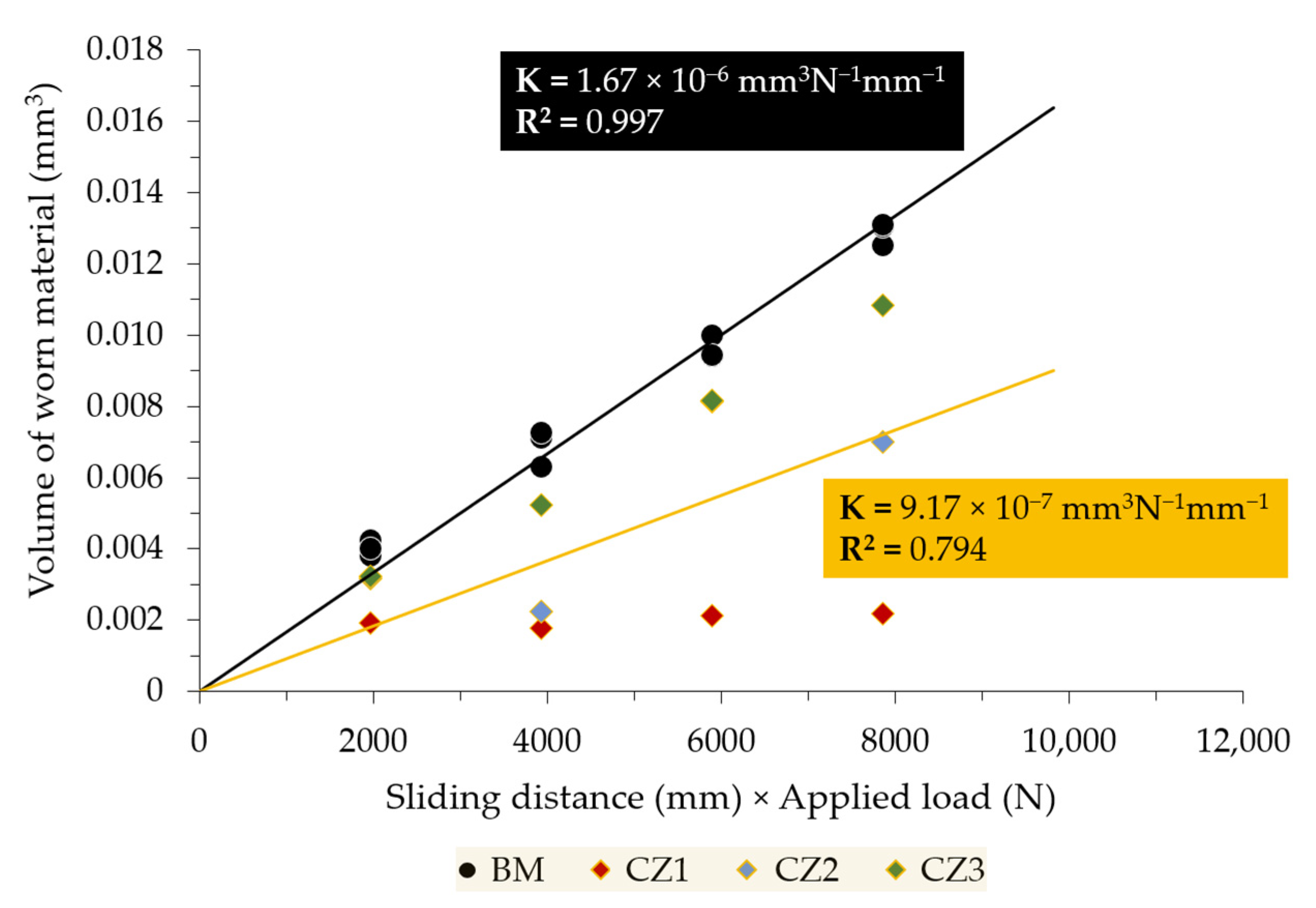
3.2. Abrasive Wear Resistance Characterization of the Reinforced Specimens

Figure 7 compares the abrasive wear rate of the reinforcement and the base metal. The wear rate (K) was calculated by taking the slope of the trend line that fits the experimental data of the volume of the worn material as a function of the sliding distance. The data points of each zone (CZ1, CZ2, and CZ3) are depicted in the graph and were all used to calculate the trend line and, consequently, the global wear rate of the reinforcement. The results show that the overall wear rate of the composite produced is 45% lower than the wear rate of the base metal. Further, the CZ1 zone shows higher wear resistance, which is in line with the high percentage of hard WC particles precipitated in the matrix of martensite (α’). It should be noted that this zone contains the highest percentage of WC (~53%), which is the hardest phase in the composite (1717 ± 147 HV 0.1). The wear performance achieved in this zone seems to be in agreement with the results found by other authors, which reported a 40% decrease in the wear rate of high-Cr cast irons reinforced by composites with 40 vol.% WC [18,19].
In the case of the CZ3 zone, the carbides present, in a much smaller amount (28%), are less hard (1521 ± 160 HV 0.1 and 1587 ± 186 HV 0.1) due to their lower W content. In addition, these carbides are precipitated in a softer austenite matrix, and, consequently, the CZ3 zone exhibits a higher wear rate, being close to that of the base metal. An intermediate behavior is observed in the CZ2 zone, composed of a mixture of different types of carbides, of which 42% are WC and 9% are W-poor carbides.
The worn surface of the tested samples was examined by OM to identify distinct features of the wear craters. Figure 8 shows a low magnification view of the wear craters corresponding to a sliding distance of 15.7 m. It can be observed that WC particles are embedded on the worn surface, effectively resisting the microcutting action of the abrasive particles. Due to this, the wear craters of CZ1 and CZ2 are significantly smaller (Figure 8a,b) than the worn crater of the base metal (Figure 8d). The results of CZ3 (Figure 8c) indicate that the interdendritic network of (Fe,Cr,W)7C3, (Fe,Cr,W)23C6, and (Fe,W,Cr)6C is less effective in increasing the wear resistance of the stainless steel.
The surfaces of the worn samples were also analyzed by SEM to investigate the factors influencing the wear resistance. Low magnification images of the worn surfaces (Figure 9) allowed identifying differences between the composite zones. In the CZ1 and CZ2 zones, the matrix shows few and shallow wear grooves, and WC particles appear in relief (see Figure 9a,b). No fractures or pull-outs are observed, indicating that the WC particles are effectively bonded to the matrix, exerting a protective effect. Previous studies have demonstrated this protective effect of the WC particles on gray cast iron and high-Cr white cast iron [18,19,20,21,22,23]. The CZ3 zone shows a higher density of narrower and deeper grooves. Additionally, the matrix is preferentially worn, and some plastic deformation is visible in the interdendritic network of (Fe,Cr,W)7C3, (Fe,Cr,W)23C6, and (Fe,W,Cr)6C. The wear of the base metal is higher than in the composite region, as mentioned above. There is a greater density of deeper grooves, indicating a high plastic deformation associated with the lower hardness of the austenite.

4. Conclusions

The development of local reinforcements of metal matrix composites (MMCs) reinforced with carbides allows strengthening austenitic stainless steel cast components, thus enhancing their surface wear resistance. The production of reinforced cast components by the proposed technique implies additional manufacturing steps: preparing the Fe-WC inserts and fixing them in the mold cavity. The process is completed with the pouring of the liquid metal.
The WC-MMC produced exhibits a microstructural gradient across its depth. The microstructure nearest to the surface is essentially composed of large polygonal-shaped WC particles in a martensite matrix, while the zone closest to the base metal shows an interdendritic network of (Fe,Cr,W)7C3, (Fe,Cr,W)23C6, and (Fe,W,Cr)6C in the matrix of austenite.
The microstructural evolution along the reinforcement is associated with a decrease in hardness from 655 ± 92 HV 2 (surface zone) to 399 ± 59 HV 2 (interface zone), meaning that the surface zone of the reinforcement is four times harder than the base metal (156 ± 10 HV 2).
The approach based on Fe-WC inserts produced by an ex situ technique was demonstrated to provide a significant increase in the wear performance of the austenitic stainless steel, resulting in a decrease of 45% of the wear rate.

Author Contributions

Conceptualization, A.B.M.; Formal analysis, L.M.M.R. and M.F.V.; Funding acquisition, M.F.V.; Investigation, A.B.M.; Supervision, L.M.M.R. and M.F.V.; Validation, L.M.M.R. and M.F.V.; Writing—original draft, A.B.M.; Writing—review and editing, L.M.M.R. and M.F.V. All authors have read and agreed to the published version of the manuscript.

Funding

This research was funded by national funds through FCT—Fundação para a Ciência e a Tecnologia, I.P., under project references UIDB/50022/2020 and UIDP/50022/2020, and by FEDER through program P2020|Norte2020, Programas doutorais (NORTE-08-5369-FSE-000051).

Institutional Review Board Statement

Not applicable.

Informed Consent Statement

Not applicable.

Data Availability Statement

Not applicable.

Acknowledgments

The authors are grateful to CEMUP (Centro de Materiais da Universidade do Porto) for the expert assistance with SEM.

Conflicts of Interest

The authors declare no conflict of interest.

References

  1. Padilha, A.F.; Rios, P.R. Decomposition of austenite in austenitic stainless steels. ISIJ Int. 2002, 42, 325–327. [Google Scholar] [CrossRef]
  2. McGuire, M.F. Austenitic Stainless Steels. In Stainless Steels for Design Engineers; ASM International: Materials Park, OH, USA, 2008. [Google Scholar]
  3. Davis, J.R. ASM Specialty Handbook: Stainless Steels; ASM International: Materials Park, OH, USA, 1994; Volume 89. [Google Scholar]
  4. Farrar, J.C.M. Group E: Standard austenitic stainless steels. In The Alloy Tree: A Guide to Low-Alloy Steels, Stainless Steels and Nickel-Base Alloys; CRC Press: Boca Raton, FL, USA, 2004. [Google Scholar]
  5. Straffelini, G. Friction and Wear: Methodologies for Design and Control; Springer: Cham, Switzerland, 2015. [Google Scholar] [CrossRef]
  6. Cuevas, A.C.; Becerril, E.B.; Martínez, M.S.; Ruiz, J.L. Fabrication Processes for Metal Matrix Composites. In Metal Matrix Composites: Wetting and Infiltration; Springer: Cham, Switzerland, 2018; pp. 83–114. [Google Scholar] [CrossRef]
  7. Manu, K.S.; Raag, L.A.; Rajan, T.; Gupta, M.; Pai, B. Liquid Metal Infiltration Processing of Metallic Composites: A Critical Review. Metall. Mater. Trans. B 2016, 47, 2799–2819. [Google Scholar] [CrossRef]
  8. Chawla, N.; Chawla, K.K. Processing. In Metal Matrix Composites, 2nd ed.; Springer: New York, NY, USA, 2013; pp. 55–97. [Google Scholar] [CrossRef] [Green Version]
  9. Li, Z.L.; Chen, Z.H.; Jiang, Y.H.; Zhou, R.; Shan, Q.; Song, Q.L. Influence of Addition of Tungsten-iron powder on Microstructure of WC/steel Composite Coatings. Adv. Mater. Res. 2012, 463–464, 394–398. [Google Scholar] [CrossRef]
  10. Shan, Q.; Li, Z.; Jiang, Y.; Zhou, R.; Sui, Y. Effect of Ni addition on microstructure of matrix in casting tungsten carbide particle reinforced composite. J. Mater. Sci. Technol. 2013, 29, 720–724. [Google Scholar] [CrossRef]
  11. Huang, R.Q.; Li, Z.L.; Jiang, Y.H.; Zhou, R.; Gao, F. Thermal Shock Cracks Initiation and Propagation of WCP/Steel Substrate Surface Composite at 500 °C. Appl. Mech. Mater. 2012, 109, 253–260. [Google Scholar] [CrossRef]
  12. Li, Z.; Jiang, Y.; Zhou, R.; Gao, F.; Shan, Q.; Tan, J. Thermal fatigue mechanism of WC particles reinforced steel substrate surface composite at different thermal shock temperatures. J. Alloy. Compd. 2014, 596, 48–54. [Google Scholar] [CrossRef]
  13. Sui, Y.; Han, L.; Jiang, Y.; Li, Z.; Shan, Q. Effects of Ni60WC25 powder content on the microstructure and wear properties of WCp reinforced surface metal matrix composites. Trans. Indian Inst. Met. 2018, 71, 2415–2422. [Google Scholar] [CrossRef]
  14. Zhang, Z.; Chen, Y.; Zuo, L.; Zhang, Y.; Qi, Y.; Gao, K.; Liu, H.; Wang, X. In situ synthesis WC reinforced iron surface composite produced by spark plasma sintering and casting. Mater. Lett. 2018, 210, 227–230. [Google Scholar] [CrossRef]
  15. Zhang, G.-S.; Xing, J.-D.; Gao, Y.-M. Impact wear resistance of WC/Hadfield steel composite and its interfacial characteristics. Wear 2006, 260, 728–734. [Google Scholar] [CrossRef]
  16. Chumanov, I.V.; Anikeev, A.N.; Chumanov, V.I. Fabrication of functionally graded materials by introducing wolframium carbide dispersed particles during centrifugal casting and examination of FGM’s structure. Procedia Eng. 2015, 129, 816–820. [Google Scholar] [CrossRef] [Green Version]
  17. Moreira, A.B.; Ribeiro, L.M.; Lacerda, P.; Pinto, A.M.; Vieira, M.F. Production and Characterization of Austenitic Stainless Steel Cast Parts Reinforced with WC Particles Fabricated by Ex Situ Technique. Materials 2021, 14, 7855. [Google Scholar] [CrossRef] [PubMed]
  18. Zhou, R.; Jiang, Y.; Lu, D. The effect of volume fraction of WC particles on erosion resistance of WC reinforced iron matrix surface composites. Wear 2003, 255, 134–138. [Google Scholar] [CrossRef]
  19. Moreira, A.B.; Ribeiro, L.M.M.; Lacerda, P.; Vieira, M.F. Characterization of Iron-Matrix Composites Reinforced by In Situ TiC and Ex Situ WC Fabricated by Casting. Metals 2021, 11, 862. [Google Scholar] [CrossRef]
  20. Li, Z.; Jiang, Y.; Zhou, R.; Lu, D.; Zhou, R. Dry three-body abrasive wear behavior of WC reinforced iron matrix surface composites produced by V-EPC infiltration casting process. Wear 2007, 262, 649–654. [Google Scholar] [CrossRef]
  21. Li, Y.; Gao, Y. Three-body abrasive wear behavior of CC/high-Cr WCI composite and its interfacial characteristics. Wear 2010, 268, 511–518. [Google Scholar] [CrossRef]
  22. Zheng, K.; Gao, Y.; Tang, S.; Li, Y.; Ma, S.; Yi, D.; Zhang, Z. Interface Structure and Wear Behavior of Cr26 Ferrous Matrix Surface Composites Reinforced with CTCp. Tribol. Lett. 2014, 54, 15–23. [Google Scholar] [CrossRef]
  23. Zhang, G.S.; Gao, Y.M.; Xing, J.D.; Wei, S.Z.; Zhang, X.L. Interfacial Characteristics and Wear Resistance of WCp/White-Cast-Iron Composites. Adv. Mater. Res. 2007, 26–28, 293–296. [Google Scholar] [CrossRef]
Figure 1. Multistep manufacturing process of the reinforced specimens.
Metals 12 00713 g001
Figure 2. Microscale abrasion tester and selected parameters.
Metals 12 00713 g002
Figure 3. OM image of the austenitic stainless steel after solution heat treatment (1075 °C/2 h) (a), and at higher magnification (b). Microstructure revealed by etching with 10% oxalic acid.
Metals 12 00713 g003
Figure 4. SEM-BSE images of the microstructure of the composite zone: (a) zone nearest surface—CZ1, (b) higher magnification of (a) showing large polygonal-shaped WC particles and precipitation of (Fe,W,Cr)6C and (Fe,W,Cr)3C; (c) intermediate zone—CZ2, (d) higher magnification of (b) showing (Fe,W,Cr)6C precipitated around a WC particle and carbides with a core of (Fe,Cr,W)7C3 and a shell of (Fe,Cr,W)23C6; (e) inner zone near to the base metal—CZ3, and (f) higher magnification of (e) showing the interdendritic network of (Fe,Cr,W)7C3, (Fe,Cr,W)23C6, and (Fe,W,Cr)6C and fine precipitates of (Fe,W,Cr)6C in the γ matrix.
Metals 12 00713 g004
Figure 5. Amount of carbides present in each composite zone.
Metals 12 00713 g005
Figure 6. Vickers hardness variation from the CZ1 zone to the base metal (BM).
Metals 12 00713 g006
Figure 7. Volume of worn material as a function of the sliding distance under a constant load of 0.25 N for the reinforced zone and the base metal.
Metals 12 00713 g007
Figure 8. OM images of the worn craters corresponding to a sliding distance of 15.7 m: (a) CZ1 composite zone, (b) CZ2 composite zone, (c) CZ3 composite zone, and (d) base metal.
Metals 12 00713 g008
Figure 9. SEM images of the wear craters after a sliding distance of 31.4 m: (a,b) CZ1 composite zone, (c,d) CZ2 composite zone, (e,f) CZ3 composite zone (g,h) base metal; (a,c,e,g) are regions close to the edge of the crater, and (b,d,f,h) are regions of the surface of the crater.
Metals 12 00713 g009
Table 1. Hardness of the precipitated carbides in the composite zones.
WC(Fe,W,Cr)6C(Fe,W,Cr)3C(Fe,Cr,W)7C3/(Fe,Cr,W)23C6
HV 0.11717 ± 1471521 ± 160
HV 0.025 1363 ± 1501587 ± 186
Composite zoneCZ1, CZ2CZ1, CZ2, CZ3CZ1CZ2, CZ3
Publisher’s Note: MDPI stays neutral with regard to jurisdictional claims in published maps and institutional affiliations.

