Article

[(AlxTi1−x)-(FeCoNi)12](AlxTi1−x)0.5Cr2.5 High-Entropy Alloy Coating by Laser Cladding

1
College of Materials and Metallurgy, Guizhou University, Guiyang 550025, China
2
Key Laboratory of Advanced Manufacturing Technology of the Ministry of Education, Guizhou University, Guiyang 550025, China
*
Author to whom correspondence should be addressed.
Metals 2022, 12(5), 740; https://doi.org/10.3390/met12050740
Submission received: 8 March 2022 / Revised: 16 April 2022 / Accepted: 19 April 2022 / Published: 27 April 2022

Abstract

:
To prolong the service life of the stirrer impeller made by SUS 904L austenitic super-stainless steel, a series of [(AlxTi1−x)-(FeCoNi)12](AlxTi1−x)0.5Cr2.5 high-entropy alloy (HEA) compositions were designed based on the cluster-plus-glue-atom model. The HEAs’ coatings were successfully fabricated by laser cladding technology. The microstructure, microhardness, wear resistance and corrosion resistance were measured by a scanning electron microscope, transmission electron microscope, microhardness tester, wear machine and electrochemical workstation, respectively. The experimental results indicate that the phase structures of the [(AlxTi1−x)-(FeCoNi)12](AlxTi1−x)0.5Cr2.5 (x = 0, 0.5, 1) HEA coatings mainly consist of a single face-centered-cubic solid solution and the coatings produce BCC phase with the increase of Ti content. When x = 0, the coating has the highest hardness (402.3 HV0.2) which is 1.92 times that of 904L austenitic super-stainless steel (209.0 HV0.2), the lowest wear volume (0.866 mm3) and the best corrosion resistance. The addition of Ti refined the microstructure of the coatings and promoted the formation of BCC phase, which improved the hardness and wear resistance of the coatings. Considering the wide sources of Ti, Fe and Co elements and the convenience of laser cladding, the coating can provide a cheap protective layer for 904L stainless steel.

Graphical Abstract

1. Introduction

904L austenitic super-stainless steel with excellent corrosion resistance is usually applied to the stirrer impeller in a phosphoric acid reactor. However, the low hardness is disadvantageous to the service life of the blade. Therefore, the design of a new material with high hardness and corrosion resistance has attracted great attention in the metallic community. Normally, the design principle of stainless steel is to introduce Cr to form passivation film of Cr2O3 on steel. Nevertheless, the matrix of the traditional stainless steel is mainly dominated by Fe, the addition of high Cr into an Fe-based alloy will lead to the formation of σ phase, resulting in the decrease of corrosion resistance. In recent years, FeCoNiCr-M high-entropy alloys (HEAs) have been extensively investigated because of their excellent properties [1,2]. Here, the M stands for other metals such as Al, Mn, Ti, etc.
HEAs are composed of multiple principle metallic elements in equiatomic or near-equiatomic ratios. They usually preferably form only one or two solid solutions [3], rather than intermetallic compounds. The lattice of HEAs is highly distorted, deprived from the difference of atomic sizes among elements, which impedes the atomic movement and slows down the diffusion rate of atoms to possess the strengthening effect in high-solid-soluted HEAs. Previous studies have revealed that the excellent properties of HEAs, such as high hardness and wear resistance [4,5,6], excellent corrosion resistance [7,8,9,10,11,12,13] as well as a trade-off of strength and ductility [14,15,16], which make them a promising candidate for the agitator blades. However, the HEAs of traditional smelting are unable to produce large size samples due to the limitation of the melting furnace, and FeCoNiCr-M HEAs contain a large number of Ni, Co and other precious metallic elements, leading to a high cost. As a result, manufacturing HEAs’ coatings offers significant cost savings. Laser cladding is a common method to prepare HEAs’ coatings and has the characteristics of ultra-fast heating and ultra-fast solidification, the as-solidified microstructure can be refined and supersaturated [17], which is beneficial to improving the strength, hardness and corrosion resistance. Therefore, choosing a suitable coating material with laser cladding technology may prolong the service life of the 904L stirrer impeller.
FeCoNiCrAlTi belongs to 3D transitional-group-element HEAs with the addition of Al or Ti elements. The effect of Al or Ti on the microstructures and mechanical properties was studied, and they show a strong influence on microstructure and phase composition [18]. Zhang et al., introduced an AlCoCrCuFeNi HEAs coating using laser cladding with ultrasonic treatment, the results showed the coating has significantly high hardness, high wear resistance and corrosion resistance. A. I. Yurkova et al., replaced the Ni element in FeCoNiCrAlV with Ti, the result showed that the hardness of the alloy increased from 12.6 ± 0.6 GPa to 14.7 ± 0.7 GPa [19]. The study conducted by Shi et al., showed that Al plays an important role in the anti-corrosion properties of FeCoCrNi HEAs [20]. The results of Huang et al., indicated that Ti could induce the formation of B2 (ordered BCC) and L12 (ordered FCC) structures, the lattice mismatch is increased between the precipitates and the matrix, which improved the impact of solution strengthening [21]. In conclusion, the FeCoNiCr-(Al/Ti) series HEAs are potential corrosion resistant materials. If the composition can be reasonably designed, a coating material with both corrosion resistance and hardness can be obtained. Nevertheless, the ratio of elements in HEA is mostly designed based on the molar ratio, the addition of alloying elements is conducted by trial and error, and compositional design is implemented without theoretical guidance. Alloys including HEA, usually form disordered solid solutions which illustrates the apparent presence of a short-range ordered structure, an important factor in the formation of the structure is the mixing enthalpy. On the one hand, cluster theory is a method to design short-range ordered structures which is consistent with the structure of HEAs, on the other hand, the mixing enthalpy between elements of FeCoNiCr-(Al/Ti) series of HEAs also fulfills the cluster formation condition. Therefore, cluster theory may be used to design the ideal composition [22].
In this paper, [(AlxTi1−x)-(FeCoNi)12](AlxTi1−x)0.5Cr2.5 (x = 0, 0.5, 1) HEAs with an FCC-structure were designed using a cluster-plus-glue-atom model, this material could be used to protect 904L stainless steel and repair damaged stirrer impellers. The [(AlxTi1−x)-(FeCoNi)12](AlxTi1−x)0.5Cr2.5 (x = 0, 0.5, 1) coatings were fabricated by laser cladding on 904L steel. For the sake of introduction, the coating is abbreviated as AlxTi1−x. It is noted that when x = 0, 0.5, 1, the coatings are simply named Al0Ti1, Al0.5Ti0.5, and Al1Ti0, respectively.

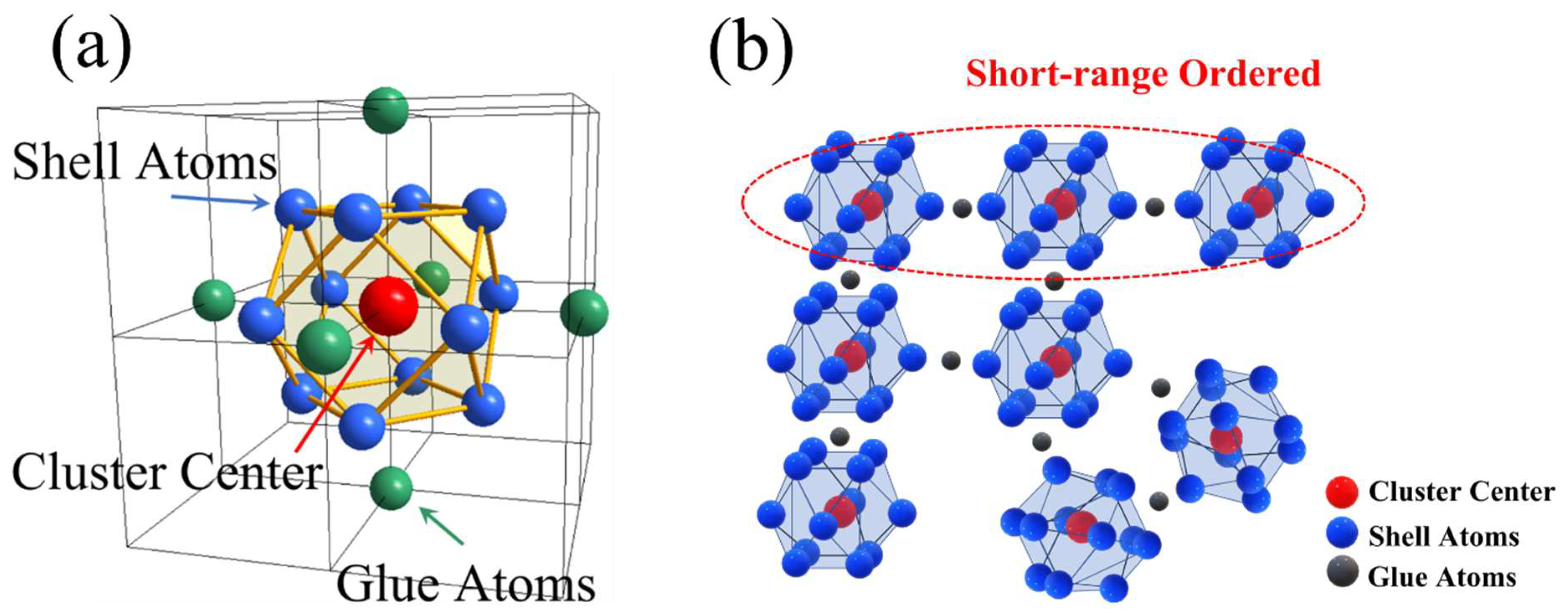
2. Compositional Design Based on Cluster-Plus-Glue-Atom Model

The cluster-plus-glue-atom model not only accurately describes the ideal structure of the solid solution, but also clearly indicates the atom occupancy in the lattice. The FCC model based on Dong’s theory consists of two parts: (1) a cluster consisting of a central atom and its nearest neighbor 12 atoms, (2) a glue atom (the glue atom number one–six for matching one cluster). In summary, the cluster formula based on the cluster-plus-glue-atom model is [C-M12]Gx (x = 1~6), where C is cluster center, M is cluster shell, and G is glue atoms. Figure 1a,b shows the cluster-plus-glue-atom model of FCC solid solutions and the short-range ordered structure between clusters. One or more clusters provide short-range ordered structure while glue atoms prevent clusters forming long-range ordered structures, which could avoid segregation effectively. In this model, the occupancy of solvent and solute atoms is determined by the mixing enthalpy between the solvent and solute atoms. Generally, the solvent atoms prior to occupying the cluster shell. The solute atom with strong interaction with the solvent is chosen as the cluster center. Contrarily, the other one showing positive interaction with the solvent is selected as the glue atoms. At present, this theory has been successfully applied in maraging steels and the low-elastic-modulus β-Ti alloy [23,24].
The eighth subgroup elements Fe, Co and Ni with similar atomic properties and weak mutual interaction (they can be regarded as the average virtual atom M), are taken as shell elements. The interaction of Al and Ti with Fe, Co and Ni (the most negative mixing enthalpy) is strong, thus the cluster-center solute elements are Al and Ti. Since the interaction of Cr with Fe, Co and Ni is weak, Cr is regarded as the glue atom. The mixing enthalpy between the elements is shown in Table 1. To reduce the content of Cr and to increase the hardness, Al and Ti are selected to replace part of the Cr atoms, and the model of the FCC cluster plus glue atoms was constructed as [(AlxTi1−x)-(FeCoNi)12](AlxTi1−x)0.5Cr2.5. The composition of the solid solution is further optimized, which effectively replaces the traditional alloy composition design and significantly reduces time and labor costs.

3. Material and Methods

The 904L steel with dimensions 50 mm × 30 mm × 10 mm was used as the substrate. The substrates were cleaned with ethanol to remove any dirt and oil before cladding. The pure Fe, Co, Ni, Cr, Al, and Ti powders (≥99.9%) with particle sizes ranging from 45 to 105 μm were selected as raw materials, then weighed as the nominal composition of AlxTi1−x (x = 0, 0.5, 1). These powders were dry-mixed using the ball-miller with the rotation rate of 300 rpm for 2 h, then the mixed powders were put into the vacuum drying oven. Before cladding, the mixed powders were preset on the substrate with a thickness of 1.2 mm. A 6-kW continuous-wave fiber laser system (RC-LMS-6000-R, Nanjing Zhongke Yuchen Laser Technology Co., Ltd, Nanjing, China) was used for laser cladding. The optimal cladding parameters were chosen as laser power of 2400 W, scanning speed of 5 mm/s, spot size of 20 mm × 2 mm, and argon shielding gas at 15 mL/min flow rate. The thickness of the coatings was about 750 μm after cladding.
Then the samples were cut into small pieces and polished and etched by aqua regia. In addition, their cross section was observed by a Supra-40 scanning electron microscope (SEM, Carl Zeiss, Berlin, Germany). The X-ray diffraction (XRD) analysis was conducted using X-ray equipment (X’ Pert PRO, Almelo, Netherlands) equipped with Cu Kα radiation under 45 kV and 40 mA, with a scanning speed of 10° per minute and a diffraction angle from 10° to 90°. The electrochemical polarization curve in the 0.5 mol/L H2SO4 solution was conducted by the CHI-760 electrochemical workstation(Shanghai Chenhua Instrument Co., Ltd., Shanghai, China) using a saturated calomel electrode (SCE) as the reference electrode, a platinum plate as the counter electrode, and a specimen as the working electrode. The Vickers microhardness was measured with a JMHV—1000AT (Lanzhou Time era instrument co., Ltd, Lanzhou, China) at a loading of 0.2 kg and with a dwell time of 15 s. Each microhardness value was obtained by calculating the average microhardness values of ten different regions. Additionally, the specimens for the wear test were cut as 12 mm × 5 mm × 5 mm bulks. The wear performance of the coating was investigated by the HSR-2M (Lanzhou Zhongke Kaihua Technology Development Co., Ltd., Lanzhou, China) reciprocating friction and wear tester, a Si3Ni4-ceramic ball 6 mm in diameter was chosen as the friction pair with a load of 50 N at a reciprocating wear length of 5 mm for the sliding time of 15 min. After wear, the wear morphology was observed by SEM. The three-dimensional morphology of the local wear tracks was observed by an OLS5000-SAF (Olympus, Tokyo, Japan) laser scanning confocal microscope.

4. Results

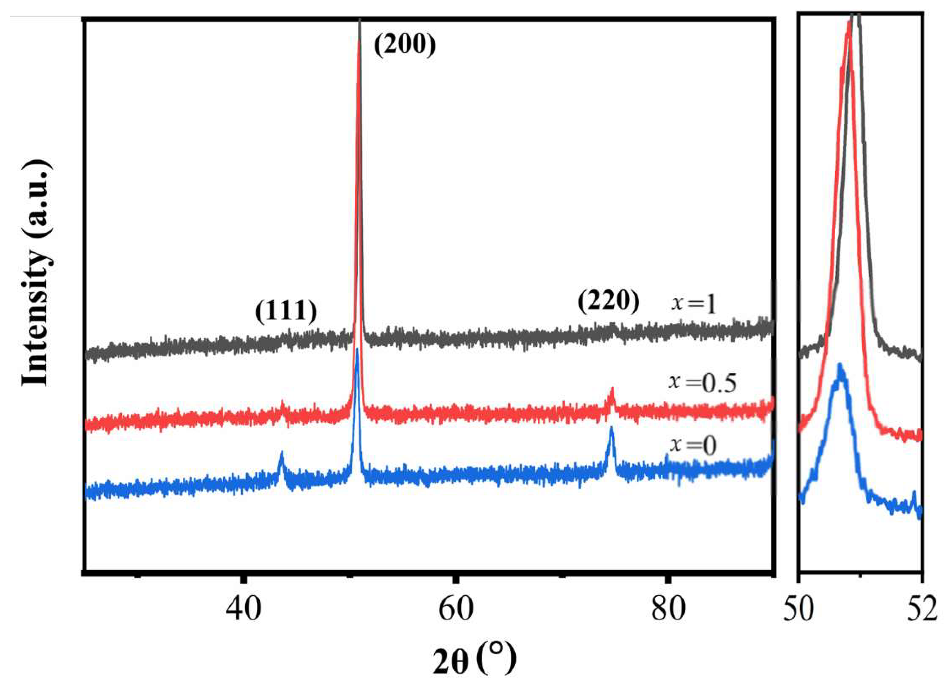
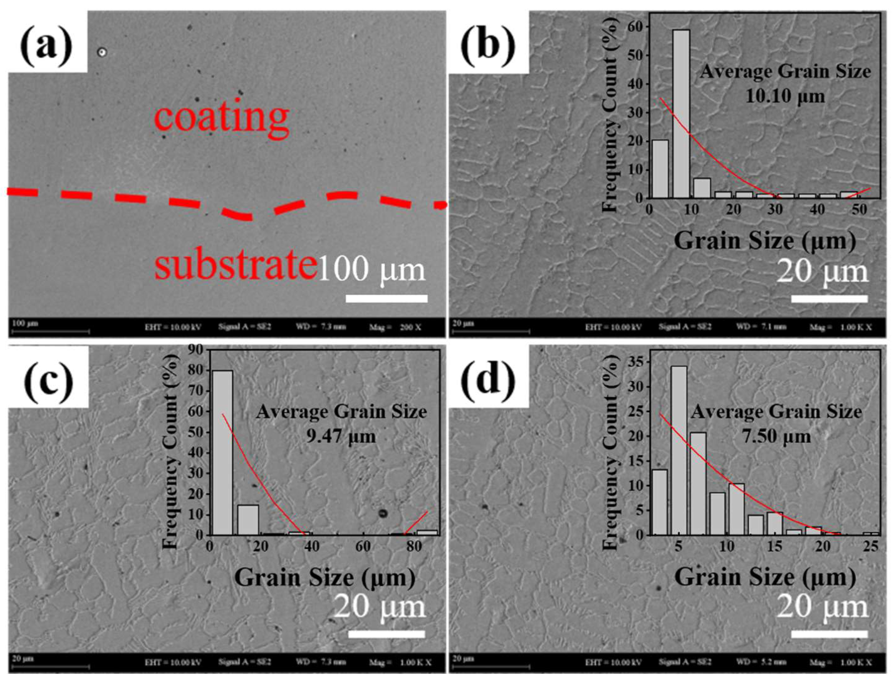
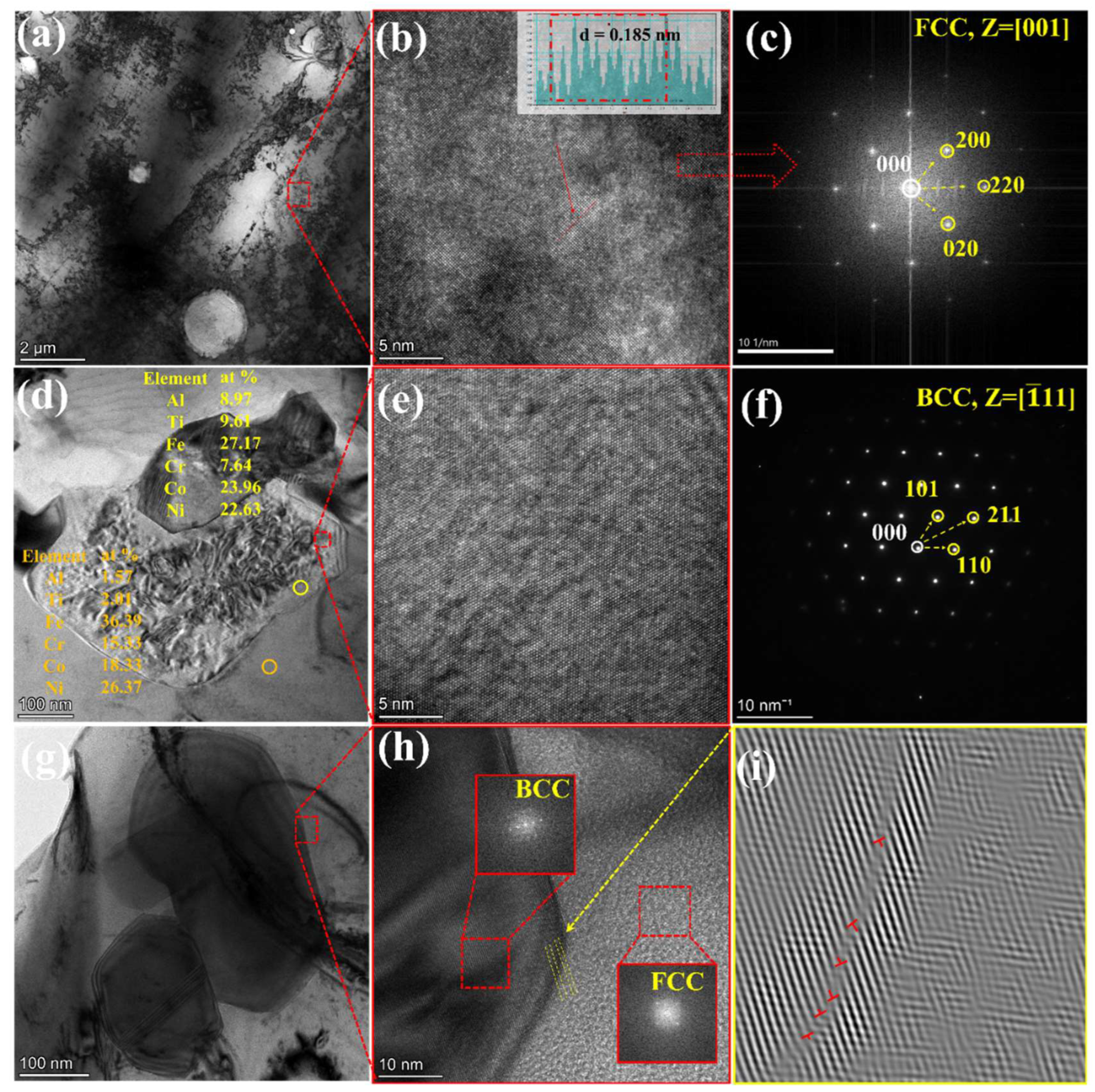
4.1. Microstructural Analysis

Thermodynamic calculation is a common method for designing solid solutions. According to Zhang and Guo’s theory [25,26], while Ω ≥ 1.1, δ ≤ 6.6 and VEC ≥ 8.0, the HEA composition is prior to forming a single FCC, where VEC is the valence electron concentration and Ω, δ are thermodynamic parameters. The calculation formulas for ΔSmix, ΔHmix, δ, Ω, etc., are as follows:
Δ S m i x = R i = 1 n c i ln c i
where R is the gas constant, c i   o r   j represents the mole fractions of element i or j;
Δ H m i x = i = 1 , i j n 4 c c i c j Δ H m i x i j
where Δ H m i x i j is the mixing enthalpy of atomic pairs and is shown in Table 1;
r ¯ = i = 1 n c i r i
δ = i = 1 n c i ( 1 r i r ¯ ) 2
where r ¯ represents the average atomic radius of elements, r i is atomic radius of the i element;
T m = i = 1 n c i T m i
Ω = T m Δ S m i x | Δ H m i x |
where T m represents the molar average melting point of the alloy and T m i is the molar melting point of the element of i;
V E C = i = 1 n c i ( V E C ) i
where ( V E C ) i is the valence electron concentration of component i. The detailed mixing enthalpy among these element pairs are shown in Table 2, and the calculated thermodynamic parameters are shown in Table 3. From Table 3, the designed HEAs meet the following conditions: Ω ≥ 1.1, δ ≤ 6.6 and VEC ≥ 8.0, which indicates that our compositional design also forms HEAs.
The XRD patterns of AlxTi1−x HEA coatings, as shown in Figure 2, detect only a single FCC solid solution, suggesting that all the HEA coatings satisfy the FCC-formation thermodynamic criteria. The angle of (200) peak gradually moves to a low angle with the increasing Ti content, and the angle of diffraction peak is 50.91°, 50.80° and 50.63°, respectively. According to formula λ = 2dsinθ, one can see the increasing lattice constant. The reflection of the (200) phase shifts to the low-angle side, indicating a slight increase in the lattice parameters of the solid solution structure, since the atomic radii of Ti are larger than other elements, which plays a role in solid solution strengthening. The diffraction spots of BCC phase in Al0Ti1 and Al0.5Ti0.5 are also found in the TEM image. The BCC phase has similar parameters to the matrix, so it is unclearly distinguished from the XRD image. These phenomena indicate that transition elements Ti can promote the formation of BCC phase, similar observations are reported in other HEAs such as FeCoNiAl [27,28].
Table 1. The mixing enthalpy among these element pairs. Adapted with permission from [29]. 2000, The Japan Institute of Metals.
ElementΔHmix (kJ/mol)
FeCoNiCrAlTi
Fe-−1−2−1−11−17
Co -0−4−19−28
Ni -−7−22−35
Cr -−10−7
Al -−30
Table 2. Thermophysical parameters of elements in HEAs [26,30].
ElementAtomic Radius (Å)CrystalTm (K)VEC
Fe1.24BCC18118
Co1.25HCP17689
Ni1.25FCC172810
Cr1.25BCC21806
Al1.43FCC9333
Ti1.46HCP19414
Table 3. Results of Tm, ΔSmix, ΔHmix, Ω, δ and VEC of AlxTi1−x (x = 0, 0.5, 1) HEAs’ coatings.
Alloy CompositionTm(K)ΔSmix(J/K·mol)ΔHmix(kJ/mol)ΩδVEC
01849.2812.90−11.902.004.91%8.06
0.51801.9112.25−102.214.59%8.02
11849.2812.90−11.902.004.91%8.06
Figure 3a shows an SEM image of the bonding interface between the substrate and Al1Ti0 HEA coating. No obvious cracks, holes or other defects exist at the interface between the coating and substrate, in which there is good metallurgical bonding [31,32,33]. Figure 3b–d shows the microstructure of AlxTi1−x alloy HEAs’ coatings for x = 0, 0.5, 1, respectively, the microstructure is translated from coarse dendrites into fine cellular crystals with the addition of Ti content. Using the software Nano Measurer, the grain size was calibrated, and the reduction of large grain size is obviously observed (shown in the inset of Figure 3). The average grain size of the coatings decreases from 10.10 to 7.50 μm with the increasing Ti content, which indicates that Ti has a significant effect on grain refinement strengthening.
Figure 4 shows the TEM (Transmission Electron Microscopy) image of the microstructure of a coating. The matrix phase can be identified as a FCC structure with about 0.185 nm of interplanar spacing of (200) in Figure 4a–c which is in good agreement with γ-(Ni,Fe) solid solution (PDF #47-1405). Figure 4d shows the bright-field TEM image of Al0.5Ti0.5, Figure 4e is the HRTEM (High Resolution TEM) image of the particle phase. Figure 4f demonstrates the SAED of particle phase, combined with the element content phase in Figure 4d, the phase is identified as B2 ([Al,Ti]Ni) ordered BCC phase. Figure 4g shows the bright-field TEM image of Al0Ti1, and Figure 4h is the HRTEM image showing the interfaces between the FCC matrix and BCC particles with FFT patterns, a large number of dislocation lines are found at the two-phase interface [see Figure 4i], this indicates that the BCC phase has dislocation hardening relative to the FCC matrix. The mixing enthalpy between Al, Ti, and Ni is negative, these elements are more likely to segregate together to form the BCC phase. Therefore, the BCC phase has dislocation strengthening and precipitation phase strengthening.

4.2. Corrosion Resistance
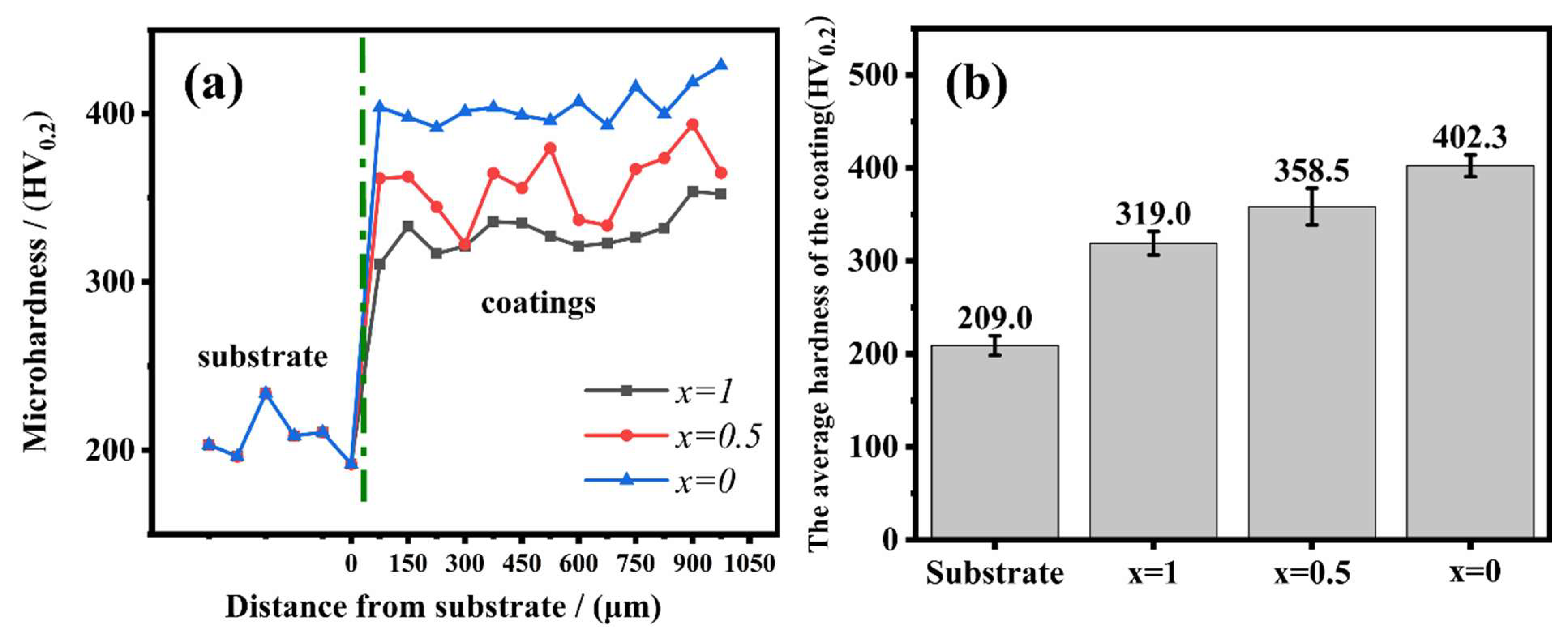
Electrochemical impedance spectroscopy (EIS) and potentiodynamic polarization are powerful tools in studying corrosion behaviors which deliver some information about the electrochemical processes occurring on the surface. The potentiodynamic polarization curves of the AlxTi1−x alloys in 0.5 mol/L H2SO4 solution at room temperature are presented in Figure 5a. The electrochemical corrosion parameters, including the corrosion potential (Ecorr), corrosion current density (Icorr), the pit potential (Epit), and passivation area (ΔE = Ecorr − Epit), calculated from the polarization curves are listed in Table 4. Generally, the higher the corrosion potential suggests that it is the more difficult to start corrosion and a lower the corrosion current suggests that the corrosion rate is lower. In addition, the wider the ΔE is, the better the pitting resistance is. The electrochemical reactions are as follows [34,35]:
Anodic:
HEA     HEA n + + n e
Cathodic:
n 4   O 2 +   n 2   H 2 O + n e   n OH
The net:
HEA   +   n 4 O 2   +   n 2   H 2 O   HEA ( OH ) n
where n is the total number of OH ions on the HEA surface, and n+ is the amount of positive charge on the HEA surface after the anodic reaction. The AlxTi1−x coatings possess a relatively larger passivation area, which indicates that the coatings have good pitting resistance. The electrochemical reactions in the active dissolution region are [36]:
Fe   + 2 OH   Fe ( OH ) 2 +   2 e +
Ni   + 2 OH   Ni ( OH ) 2 + 2 e +
Co   + 2 OH   Co ( OH ) 2 + 2 e +
Ti   + 3 H 2 O   TiO ( OH ) 2 + 2 e + + 2 H +
Cr   + 3 OH   Cr ( OH ) 3 + 3 e +
Al   + 3 OH   Al ( OH ) 3 + 3 e +
In the passivation region, Fe and Co elements will further react to form Fe(OH)3 and Co(OH)3, and they will further stabilize the passivation film.The electrochemical reactions are:
  Fe ( OH ) 2 +   OH   Fe ( OH ) 3 +   e +
  Co ( OH ) 2 +   OH   Co ( OH ) 3 +   e +
The solubility of Al(OH)3 and Ni(OH)3 in solution is much higher than that of other elements (Fe, Co Cr), the passivation film of Al-rich and Ni-rich phase is unstable, this corrosion occurs preferentially on the B2 phase [37]. The BCC phase is a hard phase, and the interface between it and the substrate has high energy. This explains that Al0.5Ti0.5 coating has the lowest corrosion potential and impedance (see Figure 5b).
Figure 5b is EIS of the AlxTi1−x coatings in 0.5 mol/L H2SO4 solution with the electrical equivalent circuit used for fitting the EIS experimental data, the fitting error is less than 5%. The Rs and R2 represent the solution resistance and charge-transfer resistance respectively, CPE is the constant phase element to compensate for non-homogeneity in the system. The arc impedance is linked to the dissolution of the metal and the larger the diameter of the impedance, the better the corrosion resistance [38,39]. The low impedance of the two Al-containing coatings indicates the deterioration effect of Al on the coatings. The impedance diameter of the Al0Ti1 coating is greater than that of the substrate, indicating excellent corrosion resistance.

4.3. Microhardness

Figure 6a,b shows the microhardness of AlxTi1−x coatings. The hardness of the coatings increases with the increasing Ti content, and it ranges from 319 HV0.2 to 402.3 HV0.2, which indicates that the influence of the Ti element is dominant. The hardness of the substrate is only 209 HV0.2. The strengthening effect of Ti on the coating is mostly attributed to grain refining strengthening, solid solution strengthening, dislocation hardening, and precipitate strengthening of the BCC phase within the matrix.

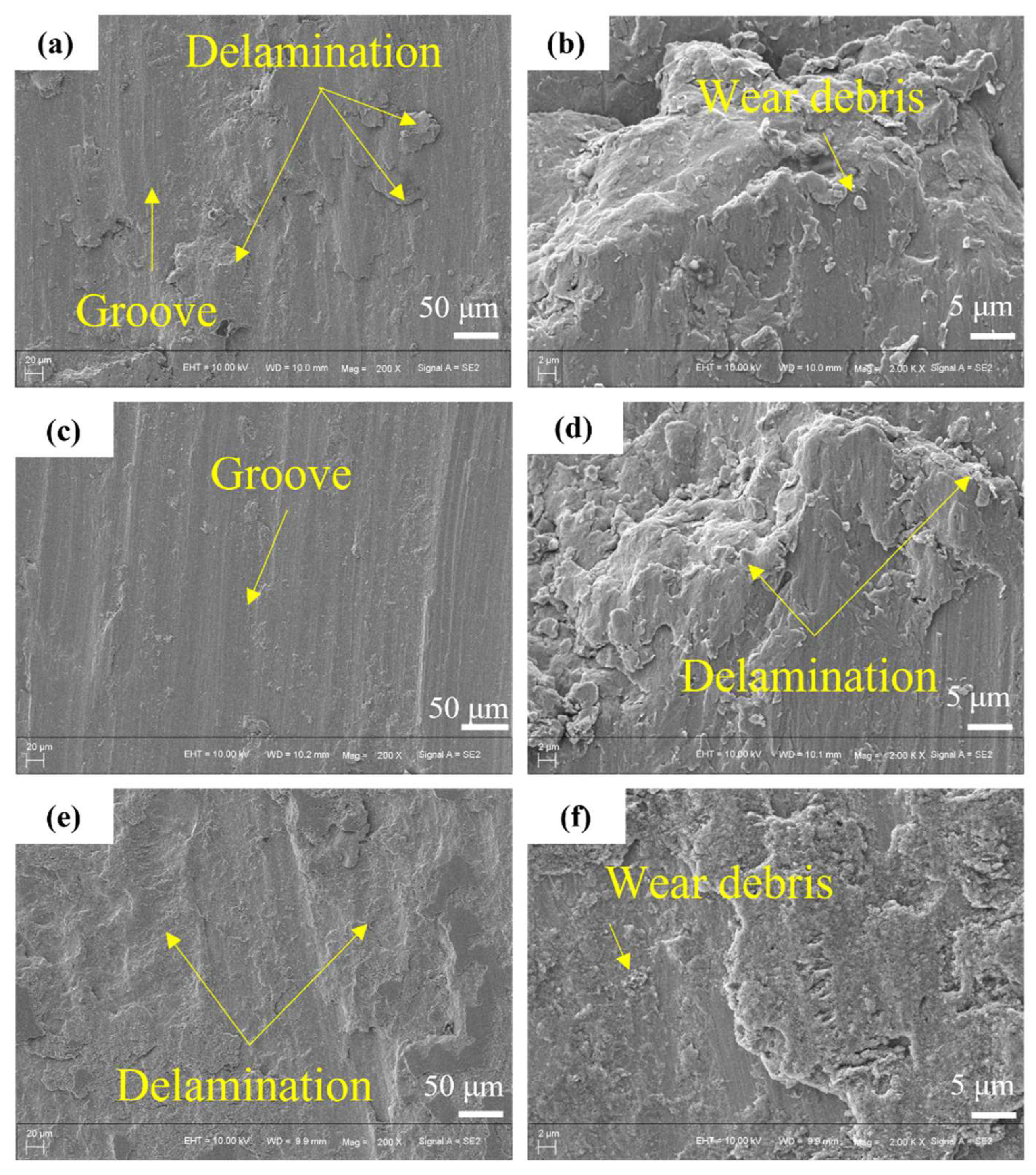
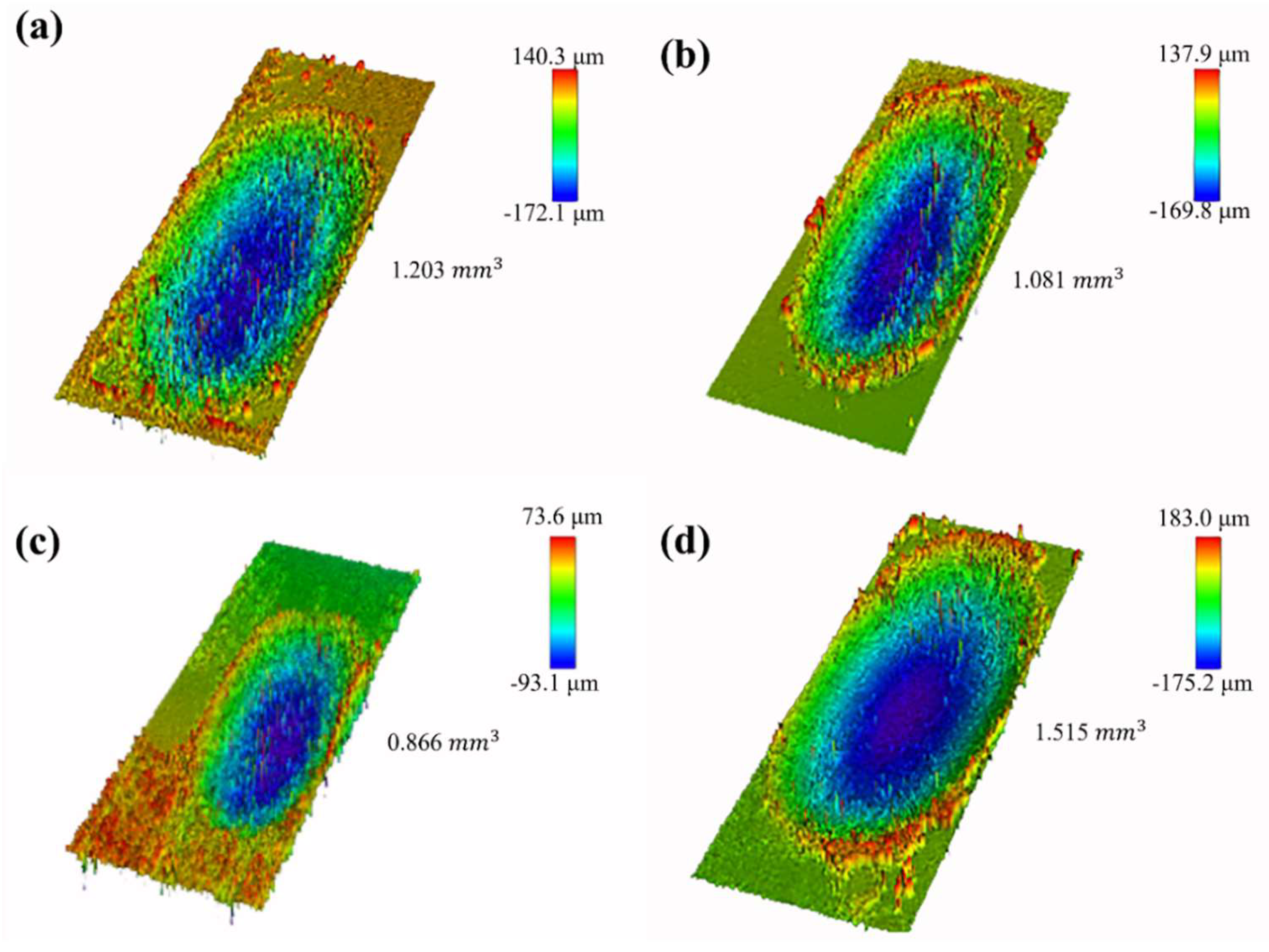
4.4. Wear Resistance

Figure 7 shows the friction coefficient curves of the substrate and AlxTi1−x HEA coatings. When x = 0, 0.5, 1, the friction coefficient of AlxTi1−x coatings is 0.57, 0.61, 0.70, respectively, while the friction coefficient of the substrate is 0.66, it is seen that the friction coefficient decreases with the increasing Ti content. The friction coefficient of Al0Ti1 and Al0.5Ti0.5 coatings are lower than that of the substrate.
In order to further analyze the wear mechanism, the wear surface was observed by SEM. Figure 8a,b shows that the stepped fractures and shallow grooves are significantly observed on the wear surface of the Al0Ti1 coating, the wear mechanism of the Al0Ti1 coating is adhesive wear and abrasive wear [30]. Figure 8c,d shows the wear surface of Al0.5Ti0.5, the wear mechanism of the Al0.5Ti0.5 coating is similar to that of the Al0Ti1 coating. Figure 8e,f shows the wear surface of Al1Ti0. The difference from the Ti-containing coatings is thata large number of piece-by-piece peelings are found in the Al1Ti0 coating, which indicates that the Al1Ti0 coating has poor wear resistance. This phenomenon could be inferred as follows: the hardness of the Al1Ti0 coating is low, the surface is easy to form initial cracks, after a certain stress cycle, the material falls off along the propagation path of the crack and the surface peels piece-by-piece [31].
Figure 9 shows 3D profiles of wear tracks and wear volume loss of HEAs’ coatings fabricated by laser cladding and substrate after a sliding time of 15 min. The wear profiles of the coatings are shallower than the substrate, indicating the better wear resistance of the coating. When x = 0, 0.5, 1, the wear volume of AlxTi1−x coatings is 1.203 mm3, 1.081 mm3, and 0.899 mm3, respectively. In summary, the improvement of Ti on material wear resistance is significant. The wear resistance of the coating is often positively correlated with hardness [32]. On the one hand, the higher hardness makes the coating less prone to initial cracks which is beneficial to the improvement of wear resistance. On the other hand, the second phase of BCC is the hindrance of dislocation which strengthens work hardening. Al0Ti1 has the lowest wear volume, which indicates that the wear resistance of the coating is optimum. Although the corrosion potential of the Al0Ti1 coating is still lower than 904L, considering the wide sources of Ti, Fe and Co elements and the convenience of laser cladding, the coating can still provide a cheap protective and repair layer for 904L stainless steel.

5. Conclusions

(1) The AlxTi1−x coatings were prepared on the surface of 904L by laser cladding. The coatings are metallurgically bonded with the substrate without obvious defects such as cracks and holes. The coarse columnar grain is gradually refined into smaller cellular grain with the increasing Ti content.
(2) The strengthening effect of Ti on coatings is mainly produced by grain refinement strengthening, solid solution strengthening, dislocation strengthening and precipitation phase strengthening which improves the wear resistance and hardness of the coatings.
(3) The AlxTi1−x coatings consisted mainly of FCC phase. Ti can promote the formation of the BCC phase including B2 phase in the coating. B2 phase contains a lot of Al and Ni elements, and the solubility of these two elements in solution is high, and the B2 phase cannot form a stable passivation.
(4) Al0Ti1 coating had a hardness of 402.3 HV0.2 and a wear volume of 0.899 mm3 in 15 min. It was highly corrosive resistant and could provide effective protection for 904L stainless steel.

Author Contributions

Investigation, S.B.; resources, S.B.; writing—original draft preparation, S.B.; writing—review and editing, S.B., Y.G. and Q.L. All authors have read and agreed to the published version of the manuscript.

Funding

This research work is supported by the National Natural Science Foundation of China (NO. 52164044); Guizhou young scientific and technological talents growth project (NO. KY [2022]137); Science and Technology project of Guizhou Province (NO. ZK [2022]053).

Institutional Review Board Statement

Not applicable.

Informed Consent Statement

Not applicable.

Data Availability Statement

The data that support the findings of this study are available from the corresponding author upon reasonable request.

Conflicts of Interest

The authors declare no conflict of interest.

References

  1. Guo, F.Y.; Yu, J.K.; Xiao, J.J.; Qiao, Q.; Yang, H.B.; Guo, Y.Q. Preparation of FeCoNiCr High Entropy Alloy Coatings and Optimization of Process Parameters. Rare Met. Mater. Eng. 2021, 50, 2337–2342. [Google Scholar]
  2. Qi, Y.; Cao, T.; Zong, H.; Wu, Y.; He, L.; Ding, X.; Jiang, F.; Jin, S.; Sha, G.; Sun, J. Enhancement of strength-ductility balance of heavy Ti and Al alloyed FeCoNiCr high-entropy alloys via boron doping. J. Mater. Sci. Technol. 2021, 75, 154–163. [Google Scholar] [CrossRef]
  3. Senkov, O.; Miller, J.; Miracle, D.; Woodward, C. Accelerated exploration of multi-principal element alloys with solid solution phases. Nat. Commun. 2015, 6, 6529. [Google Scholar] [CrossRef]
  4. Bagdasaryan, A.; Pshyk, A.; Coy, L.; Kempiński, M.; Pogrebnjak, A.; Beresnev, V.; Jurga, S. Structural and mechanical characterization of (TiZrNbHfTa)N/WN multilayered nitride coatings. Mater. Lett. 2018, 229, 364–367. [Google Scholar] [CrossRef]
  5. Mu, Y.; Zhang, L.; Xu, L.; Prashanth, K.; Zhang, N.; Ma, X.; Jia, Y.; Xu, Y.; Jia, Y.; Wang, G. Frictional Wear and Corrosion Behavior of AlCoCrFeNi High-Entropy Alloy Coatings Synthesized by Atmospheric Plasma Spraying. Entropy 2020, 22, 740. [Google Scholar] [CrossRef]
  6. Löbel, M.; Lindner, T.; Lampke, T. High-temperature wear behaviour of AlCoCrFeNiTi0.5 coatings produced by HVOF. Surf. Coat. Technol. 2020, 403, 126379. [Google Scholar] [CrossRef]
  7. Zhang, S.; Wu, C.; Zhang, C.; Guan, M.; Tan, J. Laser surface alloying of FeCoCrAlNi high-entropy alloy on 304 stainless steel to enhance corrosion and cavitation erosion resistance. Opt. Laser Technol. 2016, 84, 23–31. [Google Scholar] [CrossRef]
  8. Shang, C.; Axinte, E.; Sun, J.; Li, X.; Li, P.; Du, J.; Qiao, P.; Wang, Y. CoCrFeNi(W1−xMox) high-entropy alloy coatings with excellent mechanical properties and corrosion resistance prepared by mechanical alloying and hot pressing sintering. Mater. Des. 2017, 117, 193–202. [Google Scholar] [CrossRef]
  9. Shi, Y.Z.; Yang, B.; Liaw, P.K. Corrosion-Resistant High-Entropy Alloys: A Review. Metals 2017, 7, 43. [Google Scholar] [CrossRef] [Green Version]
  10. Luo, H.; Li, Z.; Mingers, A.M.; Raabe, D. Corrosion behavior of an equiatomic CoCrFeMnNi high-entropy alloy compared with 304 stainless steel in sulfuric acid solution. Corros. Sci. 2018, 134, 131–139. [Google Scholar] [CrossRef]
  11. Liu, J.; Liu, H.; Chen, P.; Hao, J. Microstructural characterization and corrosion behaviour of AlCoCrFeNiTix high-entropy alloy coatings fabricated by laser cladding. Surf. Coat. Technol. 2019, 361, 63–74. [Google Scholar] [CrossRef]
  12. Xiang, C.; Zhang, Z.; Fu, H.; Han, E.-H.; Zhang, H.; Wang, J. Microstructure and corrosion behavior of AlCoCrFeNiSi0.1 high-entropy alloy. Intermetallics 2019, 114, 106599. [Google Scholar] [CrossRef]
  13. Wang, L.; Zhang, F.; Yan, S.; Yu, G.; Chen, J.; He, J.; Yin, F. Microstructure evolution and mechanical properties of atmosphere plasma sprayed AlCoCrFeNi high-entropy alloy coatings under post-annealing. J. Alloys Compd. 2021, 872, 159607. [Google Scholar] [CrossRef]
  14. Li, B.; Zhang, L.; Xu, Y.; Liu, Z.; Qian, B.; Xuan, F. Selective laser melting of CoCrFeNiMn high entropy alloy powder modified with nano-TiN particles for additive manufacturing and strength enhancement: Process, particle behavior and effects. Powder Technol. 2020, 360, 509–521. [Google Scholar] [CrossRef]
  15. Wolff-Goodrich, S.; Marshal, A.; Pradeep, K.; Dehm, G.; Schneider, J.M.; Liebscher, C.H. Combinatorial exploration of B2/L21 precipitation strengthened AlCrFeNiTi compositionally complex alloys. J. Alloys Compd. 2021, 853, 156111. [Google Scholar] [CrossRef]
  16. Li, D.; Li, C.; Feng, T.; Zhang, Y.; Sha, G.; Lewandowski, J.; Liaw, P.K. High-entropy Al0.3CoCrFeNi alloy fibers with high tensile strength and ductility at ambient and cryogenic temperatures. Acta Mater. 2017, 123, 285–294. [Google Scholar] [CrossRef] [Green Version]
  17. Zhang, S.; Han, B.; Li, M.; Hu, C.; Zhang, Q.; Liu, X.; Wang, Y. Investigation on microstructure and properties of laser cladded AlCoCrCuFeNi high entropy alloy coating by ultrasonic impact treatment. Intermetallics 2021, 128, 107017. [Google Scholar] [CrossRef]
  18. Zhang, Y.; Li, R. New Advances in High-Entropy Alloys. Entropy 2020, 22, 1158. [Google Scholar] [CrossRef]
  19. Yurkova, A.I.; Nakonechnyi, S.O.; Cherniavsky, V.V.; Kushnir, V.V. Nanostructured AlCoFeCrVNi and AlCoFeCrVTi high-entropy alloys resulted from mechanical alloying and sintering. Appl. Nanosci. 2021, 1–12. [Google Scholar] [CrossRef]
  20. Shi, Y.; Yang, B.; Xie, X.; Brechtl, J.; Dahmen, K.A.; Liaw, P.K. Corrosion of Al CoCrFeNi high-entropy alloys: Al-content and potential scan-rate dependent pitting behavior. Corros. Sci. 2017, 119, 33–45. [Google Scholar] [CrossRef]
  21. Huang, X.; Huang, L.; Peng, H.; Liu, Y.; Liu, B.; Li, S. Enhancing strength-ductility synergy in a casting non-equiatomic NiCoCr-based high-entropy alloy by Al and Ti combination addition. Scr. Mater. 2021, 200, 113898. [Google Scholar] [CrossRef]
  22. Hao, C.P.; Wang, Q.; Ma, R.T.; Wang, Y.M.; Qiang, J.B.; Dong, C. Cluster-plus-glue-atom model in bcc solid solution alloys. Acta Phys. Sin. 2011, 60, 8. [Google Scholar]
  23. Wang, Q.; Zha, Q.; Liu, E.; Dong, C.; Wang, X.; Tan, C.; Ji, C. Composition design of high-strength martensitic precipitation hardening stainless steels based on a cluster model. Acta Met. Sin. 2012, 48, 1201. [Google Scholar] [CrossRef]
  24. Wang, Q.; Ji, C.; Wang, Y.; Qiang, J.; Dong, C. β-Ti Alloys with Low Young’s Moduli Interpreted by Cluster-Plus-Glue-Atom Model. Met. Mater. Trans. A 2013, 44, 1872–1879. [Google Scholar] [CrossRef]
  25. Yang, X.; Chen, S.Y.; Cotton, J.D.; Zhang, Y. Phase Stability of Low-Density, Multiprincipal Component Alloys Containing Aluminum, Magnesium, and Lithium. JOM 2014, 66, 2009–2020. [Google Scholar] [CrossRef]
  26. Guo, S.; Ng, C.; Lu, J.; Liu, C.T. Effect of valence electron concentration on stability of fcc or bcc phase in high entropy alloys. J. Appl. Phys. 2011, 109, 103505. [Google Scholar] [CrossRef] [Green Version]
  27. Zhao, Y.; Wang, M.; Cui, H.; Zhao, Y.; Song, X.; Zeng, Y.; Gao, X.; Lu, F.; Wang, C.; Song, Q. Effects of Ti-to-Al ratios on the phases, microstructures, mechanical properties, and corrosion resistance of Al2-xCoCrFeNiTix high-entropy alloys. J. Alloys Compd. 2019, 805, 585–596. [Google Scholar] [CrossRef]
  28. Ma, Y.; Wang, Q.; Jiang, B.; Li, C.; Hao, J.; Li, X.; Dong, C.; Nieh, T. Controlled formation of coherent cuboidal nanoprecipitates in body-centered cubic high-entropy alloys based on Al2(Ni,Co,Fe,Cr)14 compositions. Acta Mater. 2018, 147, 213–225. [Google Scholar] [CrossRef]
  29. Takeuchi, A.; Inoue, A. Classification of Bulk Metallic Glasses by Atomic Size Difference, Heat of Mixing and Period of Constituent Elements and Its Application to Characterization of the Main Alloying Element. Mater. Trans. 2005, 46, 2817–2829. [Google Scholar] [CrossRef] [Green Version]
  30. Miracle, D.B.; Senkov, O.N. A critical review of high entropy alloys and related concepts. Acta Mater. 2017, 122, 448–511. [Google Scholar] [CrossRef] [Green Version]
  31. Li, Y.; Cui, X.; Jin, G.; Cai, Z.; Tan, N.; Lu, B.; Gao, Z. Interfacial bonding properties between cobalt-based plasma cladding layer and substrate under tensile conditions. Mater. Des. 2017, 123, 54–63. [Google Scholar] [CrossRef]
  32. Guo, Y.; Shang, X.; Liu, Q. Microstructure and properties of in-situ TiN reinforced laser cladding CoCr2FeNiTi high-entropy alloy composite coatings. Surf. Coat. Technol. 2018, 344, 353–358. [Google Scholar] [CrossRef]
  33. Lan, H.; Liu, Q. Design of [Al-(FeCoNi)12]Al Cr3- HEAs based on cluster-plus-glue-atom model and its coating fabricated by laser cladding. Intermetallics 2020, 126, 106941. [Google Scholar] [CrossRef]
  34. Su, B.; Luo, L.; Wang, B.; Su, Y.; Wang, L.; Ritchie, R.O.; Guo, E.; Li, T.; Yang, H.; Huang, H.; et al. Annealed microstructure dependent corrosion behavior of Ti-6Al-3Nb-2Zr-1Mo alloy. J. Mater. Sci. Technol. 2021, 62, 234–248. [Google Scholar] [CrossRef]
  35. Li, J.; Lin, X.; Wang, J.; Zheng, M.; Guo, P.; Zhang, Y.; Ren, Y.; Liu, J.; Huang, W. Effect of stress-relief annealing on anodic dissolution behaviour of additive manufactured Ti-6Al-4V via laser solid forming. Corros. Sci. 2019, 153, 314–326. [Google Scholar] [CrossRef]
  36. Yen, C.-C.; Lu, H.-N.; Tsai, M.-H.; Wu, B.-W.; Lo, Y.-C.; Wang, C.-C.; Chang, S.-Y.; Yen, S.-K. Corrosion mechanism of annealed equiatomic AlCoCrFeNi tri-phase high-entropy alloy in 0.5 M H2SO4 aerated aqueous solution. Corros. Sci. 2019, 157, 462–471. [Google Scholar] [CrossRef]
  37. Liao, W.-B.; Zhang, H.; Liu, Z.-Y.; Li, P.-F.; Huang, J.-J.; Yu, C.-Y.; Lu, Y. High Strength and Deformation Mechanisms of Al0.3CoCrFeNi High-Entropy Alloy Thin Films Fabricated by Magnetron Sputtering. Entropy 2019, 21, 146. [Google Scholar] [CrossRef] [Green Version]
  38. Meghwal, A.; Anupam, A.; Luzin, V.; Schulz, C.; Hall, C.; Murty, B.; Kottada, R.S.; Berndt, C.C.; Ang, A.S.M. Multiscale mechanical performance and corrosion behaviour of plasma sprayed AlCoCrFeNi high-entropy alloy coatings. J. Alloys Compd. 2021, 854, 157140. [Google Scholar] [CrossRef]
  39. Li, Y.; Shi, Y. Microhardness, wear resistance, and corrosion resistance of AlxCrFeCoNiCu high-entropy alloy coatings on aluminum by laser cladding. Opt. Laser Technol. 2021, 134, 106632. [Google Scholar] [CrossRef]
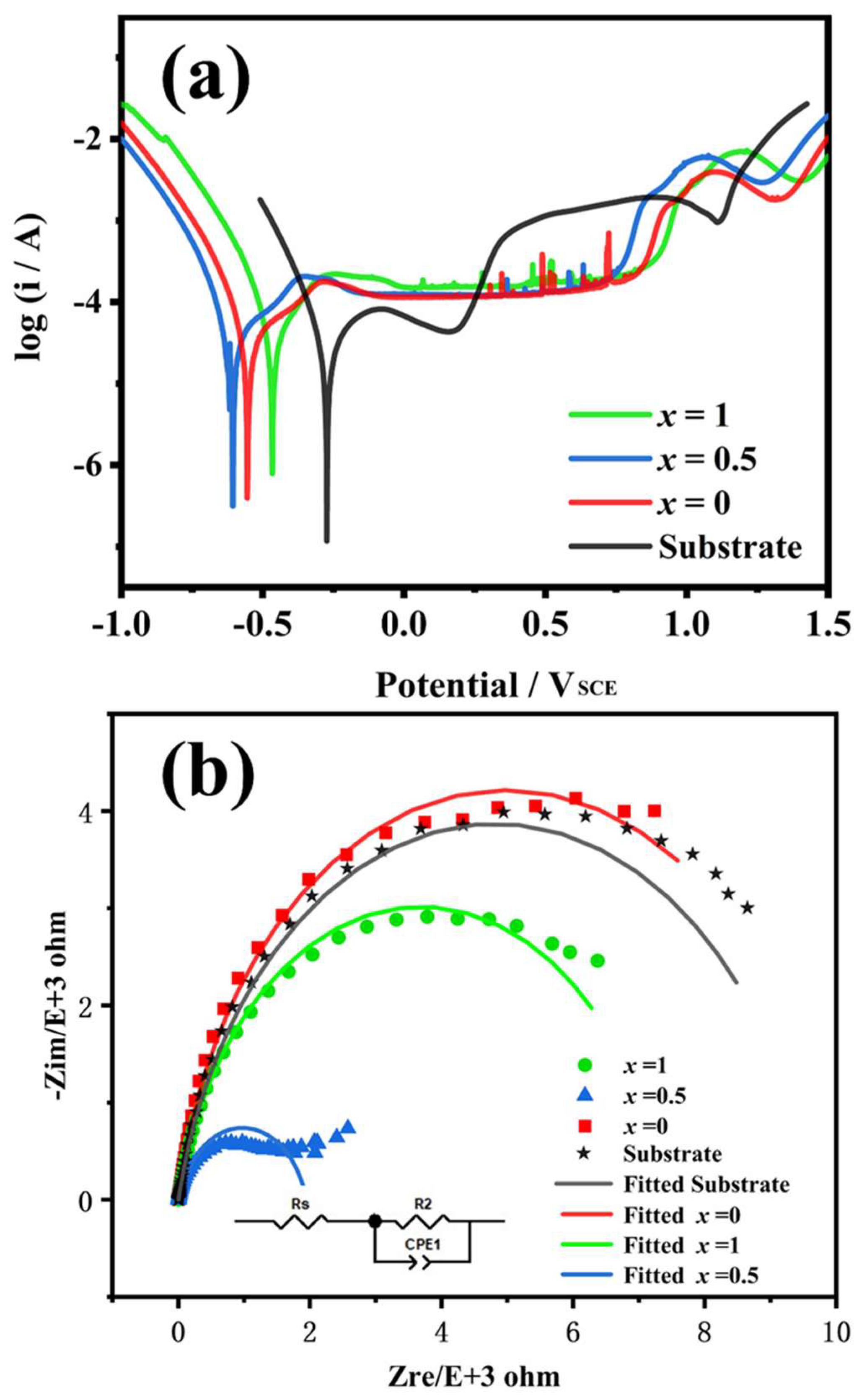
Figure 1. (a) Cluster-plus-glue-atom model of FCC solid solutions; (b) Short-range ordered.
Metals 12 00740 g001
Figure 2. XRD patterns of AlxTi1−x HEAs’ coatings.
Metals 12 00740 g002
Figure 3. Microstructure of AlxTi1−x (x = 0, 0.5, 1) HEA’s coatings: (a) Cross-section morphology of AlxTi1−x (b) Al1Ti0, (c) Al0.5Ti0.5, (d) Al0Ti1.
Metals 12 00740 g003
Figure 4. TEM image of the of AlxTi1−x (x = 0, 0.5, 1): (a) Bright-field image of Al1Ti0, (b) HRTEM images of matrix, (c) SAED patterns corresponding to (a2), (d) Bright-field image of Al0.5Ti0.5, (e) HRTEM images of particle phase from matrix, (f) SAED patterns corresponding to (e), (g) Bright-field image of Al0Ti1, (h) HRTEM image showing the interfaces between the FCC matrix and BCC particles with FFT (Fast Fourier Transform) patterns, (i) IFFF (Inverse Fast Fourier Transform) pattern of the interfaces between the FCC matrix and BCC particles.
Metals 12 00740 g004
Figure 5. (a) Potentiodynamic polarization curves of AlxTi1−x (x = 0, 0.5, 1) in 0.5 mol/L H2SO4 solution, (b) Electrochemical impedance spectroscopy AlxTi1−x (x = 0, 0.5, 1) in 0.5 mol/L H2SO4 solution.
Metals 12 00740 g005
Figure 6. Hardness of AlxTi1−x (x = 0, 0.5, 1) coatings: (a) Hardness distribution, (b) Average hardness.
Metals 12 00740 g006
Figure 7. Friction coefficient curves of AlxTi1−x(x = 0, 0.5, 1) coatings, also taking the commercial 904L stainless steel into account as a comparison.
Metals 12 00740 g007
Figure 8. Wear morphologies of AlxTi1−x coatings: (a,b) Al0Ti1, (c,d) Al0.5Ti0.5, (e,f) Al1Ti0.
Metals 12 00740 g008
Figure 9. 3D profiles of wear tracks of the AlxTi1−x coatings: (a) Al1Ti0, (b)Al0.5Ti0.5, (c) Al0Ti1, (d) Substrate.
Metals 12 00740 g009
Table 4. Electrochemical parameters of AlxTi1−x (x = 0, 0.5, 1) and 904L stainless steel in 0.5 mol/L H2SO4 solution.
Electrochemical ParametersX = 0X = 0.5X = 1Substrate
Ecorr/mVSCE−553.7−605.0−468.8−273.0
Icorr/μA cm−231.4135.6544.7733.34
Epit/mVSCE838.8756.7898.6170.8
Epit − Ecorr/mVSCE−21392.51361.71367.4443.8
Publisher’s Note: MDPI stays neutral with regard to jurisdictional claims in published maps and institutional affiliations.

