Article

Studies of High-Temperature Fatigue Behavior and Mechanism for Nickel-Based Superalloy Inconel 625

1
Institute of Process Equipment and Control Engineering, College of Mechanical Engineering, Zhejiang University of Technology, Hangzhou 310014, China
2
National Engineering Technical Research Center on PVP Safety, Hefei General Machinery Research Institute Co., Ltd., No. 888, Changjiang West Road, Hefei 230031, China
*
Author to whom correspondence should be addressed.
Metals 2022, 12(5), 755; https://doi.org/10.3390/met12050755
Submission received: 3 April 2022 / Revised: 24 April 2022 / Accepted: 27 April 2022 / Published: 28 April 2022
(This article belongs to the Special Issue Residual Stress and Fatigue of Metals)

Abstract

:
Strain-controlled continuous fatigue and creep–fatigue tests were carried out at 700 °C and 800 °C on Inconel 625 alloy. The effects of strain rate and tensile-hold time on cyclic stress response and fatigue life were investigated. Then, the microstructural analysis and the fractographic analysis of fatigue-fractured specimens were performed by scanning electron microscopy and transmission electron microscopy. The cyclic stress responses during high-temperature fatigue and the creep–fatigue–oxidation damage mechanism were discussed. The results showed that the strain rate and the tensile-hold time had little effect on the fatigue life at 700 °C, but there was a significant impact at 800 °C due to the creep–fatigue–oxidation interaction. The cyclic plastic deformation accelerated the precipitation of the γ″ phase, resulting in a continuous cyclic hardening and negative strain rate sensitivity. The fatigue failures at 700 °C under continuous fatigue conditions occurred with a transgranular fracture mode, while a transgranular-intergranular hybrid fracture manner was found at 800 °C. Furthermore, a frequency-modified total strain energy density model was proposed to consider the effects of creep and oxidation on fatigue life, and the predicted fatigue lives were located within the 1.5 times error band.

1. Introduction

Nickel-based superalloy Inconel 625 possesses a high strength, corrosion resistance, and creep resistance at elevated temperatures, which is widely used to manufacture critical high-temperature components in petrochemical, nuclear, aerospace, and power generation industries [1,2,3,4]. The actual service conditions usually involve high-temperature, high stress, and complex cyclic loading, resulting in low cycle fatigue failures of the components [5,6]. Furthermore, the microstructural evolution of Inconel 625 alloy at high temperatures may impact its mechanical properties and durability [7,8,9].
Because of the excellent competitive strength in the field of new energy power generation, concentrated solar power (CSP) with the supercritical carbon dioxide (sCO2) Brayton cycle has developed rapidly in recent years [10]. At the same time, higher requirements have been put forward for candidate materials for high-temperature components. In order to achieve the cycle efficiency of 50%, the temperature of sCO2 delivered to the power turbine must be above 700 °C, while the solar receiver needs to withstand temperatures up to 800 °C [11,12]. Due to thermal stress, internal pressure, and daily cycling, low cycle fatigue is one of the significant failure modes that needs to be considered when designing high-temperature components [13]. Inconel 625 alloy has been selected as one of the potential materials for high-temperature parts of the sCO2 cycle system [14,15]; thus, its high-temperature fatigue properties are crucial for the design work. To the best of the authors’ knowledge, little relevant literature on the low cycle fatigue behavior of Inconel 625 has been published. In 1983, Purohit et al. [16] examined the low cycle fatigue properties of Inconel 625 alloy at temperatures ranging from 650 °C to 1100 °C. Bui-Quoc et al. [6] carried out low cycle fatigue and creep–fatigue tests on Inconel 625 alloy at 650 °C and 815 °C. Their research results showed that the tensile-hold time did not affect fatigue lives at 650 °C, whereas it had a significant effect at 815 °C. However, the microstructural evolution and damage mechanism were not analyzed. Recently, Mataveli et al. [9] conducted the stress-controlled fatigue tests of Inconel 625 alloy aged at 650 °C for 500 h, showing that the S-N curve at 650 °C was about 300 MPa higher than that of the non-aged alloy. They believed that the γ″ phase precipitated during aging was the main cause of the hardening.
It is well known that some carbides and intermetallic compounds may be precipitated in the nickel-based superalloys after long-term service, which heavily affects the alloy’s mechanical properties. According to previous studies [2,8,17,18,19,20,21,22], the thin film or granular secondary M23C6 (specifically Cr23C6) carbides usually precipitate along grain boundaries in the temperature range of 600–900 °C, while the granular secondary M6C (enriched in Ni, Mo, and Cr) carbide particles precipitate at grain boundaries at 800–1100 °C. Furthermore, the Ni2(Cr,Mo)-type intermetallic compound precipitates below 600 °C, whereas the Ni3(Nb,Ti,Al) intermetallic compound (γ″ phase) precipitates at temperatures ranging from 600 °C to 850 °C. However, the metastable Ni3(Nb,Ti,Al) gradually transforms into the stable Ni3Nb-type intermetallic compound (δ phase) when the temperature is above 650 °C. The presence of secondary carbides mainly affects toughness and plasticity, while intermetallic compounds affect the hardness and mechanical strength of Inconel 625 alloy [21,22,23,24]. Moreover, the microstructure of Inconel 625 alloy is more unstable during cyclic mechanical loading at high temperatures. The cyclic deformation behavior and the damage mechanism largely depend on its microstructural evolution. Mataveli et al. [9] reported that cyclic loading greatly accelerated the precipitation of the γ” phase, leading to alloy hardening and thus limiting the cyclic ratcheting effect. They suggested that the influence of loading frequency on fatigue behaviors of Inconel 625 alloy should be investigated, but there has been little relevant research so far.
The fatigue performance of Inconel 625 alloy at 700–800 °C is crucial for the design and safety evaluation of the CSP high-temperature components, such as the solar receiver, but little data can be available. In addition, the strain rate and tensile-hold time during fatigue loading may affect the cyclic deformation behavior of alloys. Therefore, it is urgent to better understand the high-temperature fatigue properties of Inconel 625 alloy in the temperature range of 700–800 °C, as well as the effect of microstructural evolution on the cyclic deformation behavior. In this study, continuous low cycle fatigue (LCF) and tensile-hold creep–fatigue (C–F) tests of Inconel 625 alloy were carried out under the strain-controlled mode at 700 °C and 800 °C. The effects of strain amplitude, strain rate, and tensile-hold time on cyclic stress response were investigated. Then, the fractographic analysis of fatigue and the microstructural characterization were conducted to discuss the evolution of cyclic stress and the damage mechanism. Finally, an energy-based fatigue life prediction model considering the effects of creep and oxidation was established.

2. Material and Experimental Procedures

2.1. Material

The investigated material was a commercial Ni-based alloy Inconel 625 plate with a thickness of 16 mm. The chemical composition of the alloy is listed in Table 1, which was obtained by using the SPECTRO MAXx spark discharge atomic emission spectrometer (SPECTRO Inc., Kleve, Germany). The solid-solution heat treatment was conducted under the condition of 1150 °C/1 h, resulting in the equiaxed austenite grains together with twinning structures, as shown in Figure 1a. A few blocky primary MC carbides can be observed in the matrix, but other types of precipitates did not exist (Figure 1b), as they were completely dissolved during the solid-solution heat treatment [17]. Cylindrical specimens for LCF and C–F tests were machined along the rolling direction. Figure 2 shows the geometry of the specimen, the gauge length and the diameter of which were 30 mm and 8 mm, respectively. The surface roughness of the specimen was controlled at Ra 0.4 by mechanical polishing to minimize the impact of specimen machining.

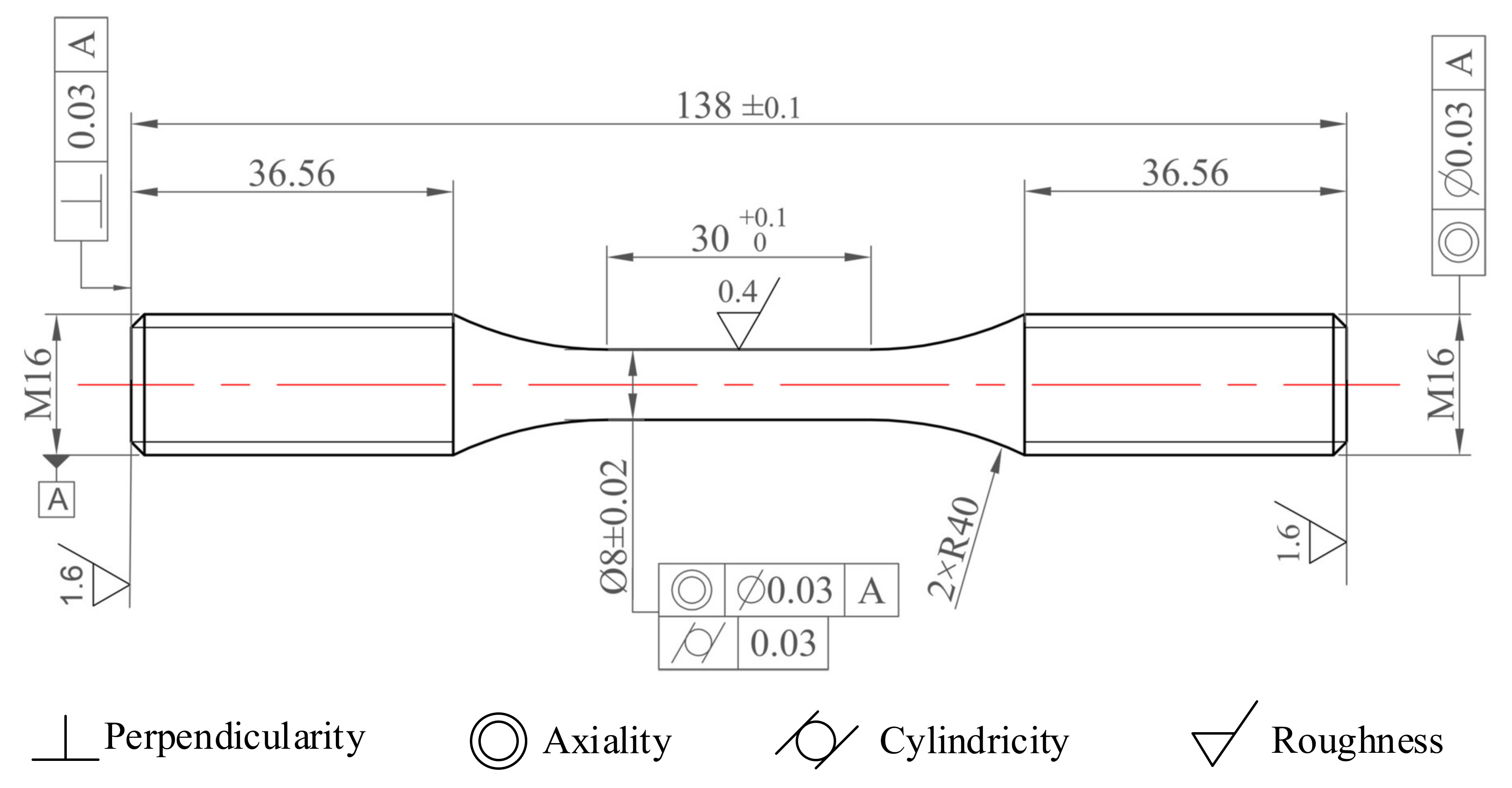
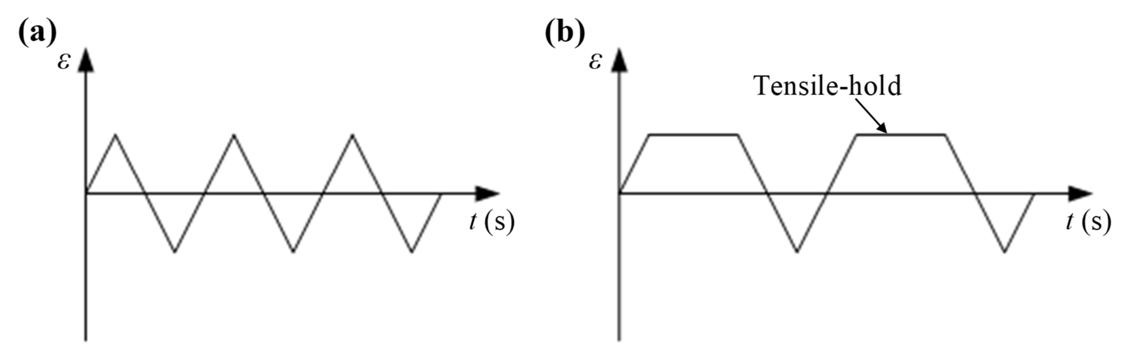
2.2. Experimental Procedure

LFC and C–F tests were conducted according to ASTM-E606-12 and ASTM E2714-13, respectively. A radio-frequency induction heating approach was utilized to heat the test specimen. The temperature fluctuation was controlled within ±2 °C by the FLUKE infrared thermometer (Fluke Inc., Everett, WA, USA). The axial strain was controlled using a high-temperature axial extensometer with quartz rods. Fully reversed (Rε = −1) strain control mode was utilized for all the fatigue tests. Five different constant strain amplitude (∆ε/2) LCF tests were carried out under the strain rate ( ε ˙ ) of 2 × 10⁻³ s−1 at 700 °C and 800 °C, respectively. In order to study the effect of strain rate, LCF tests with the strain rates of 1.6 × 10⁻⁴ and 3.2 × 10⁻⁴ s−1 were performed at the strain amplitude of 0.4%. Meanwhile, C–F tests with tensile-hold times (th) of 60 and 120 s were conducted at 700 °C and 800 °C. The loading waveforms of the LCF test and the C–F test are illustrated in Figure 3a,b, respectively. The detailed test parameters are listed in Table 2. The tests were stopped before the specimens completely fractured, in order to protect the extensometer. Fatigue life (Nf) is defined as the number of cycles when the tensile stress drops below 30% of its maximum.
For microstructural characterization, the samples were sectioned longitudinally from the fatigue-fractured specimens, mechanically polished, and then etched by a solution of 5 g CuCl2 + 100 mL HCl + 100 mL C2H5OH. Microstructural features were observed using an XJG-05 optical microscope (Nanjing Lianchuang Inc., Nanjing, China) and a ZEISS Supra 40 field emission Scanning Electron Microscope (SEM) (ZEISS Inc., Oberkochen, Germany). In addition, thin slices with a thickness of 0.5 mm were machined at a distance of 2 mm away from the fracture surface, mechanically ground down to ~50 μm, and then twin-jet electro-polished in an electrolyte of 10% HClO4 + 90% CH3OH at −20 °C/30 V. A FEI Tecnai G20 S-TWIN Transmission Electron Microscope (TEM) (FEI Inc., Hillsboro, OR, USA) was used to characterize the precipitate in the fatigue-fractured specimens.

3. Results and Discussion

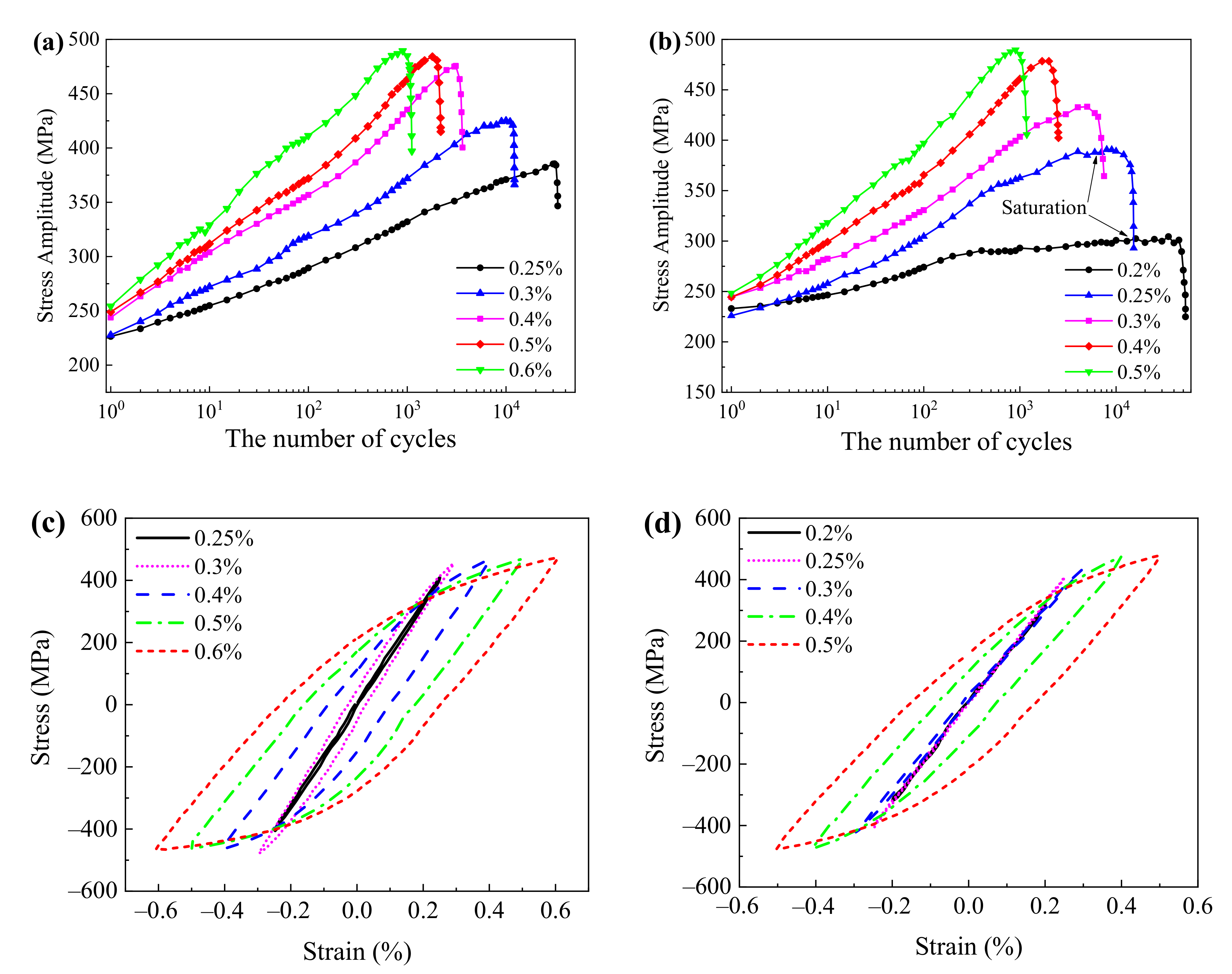
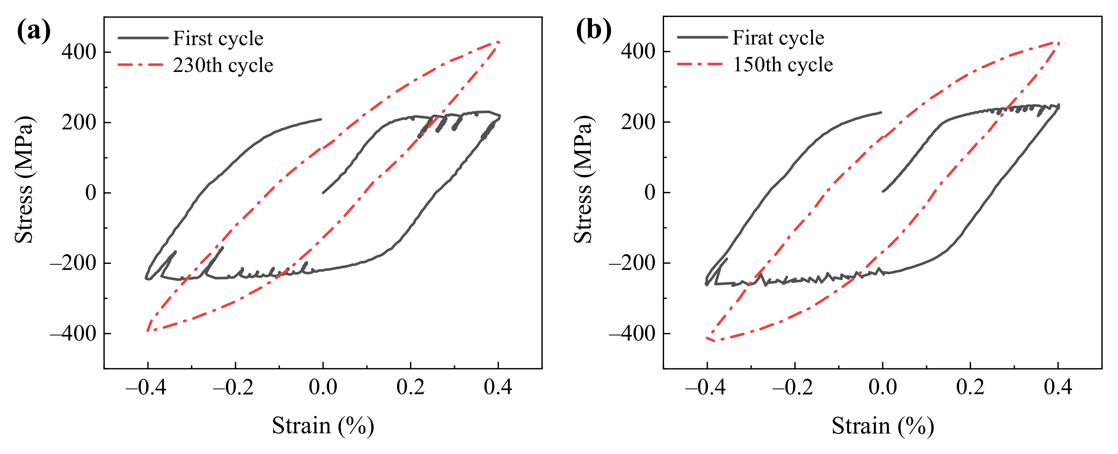
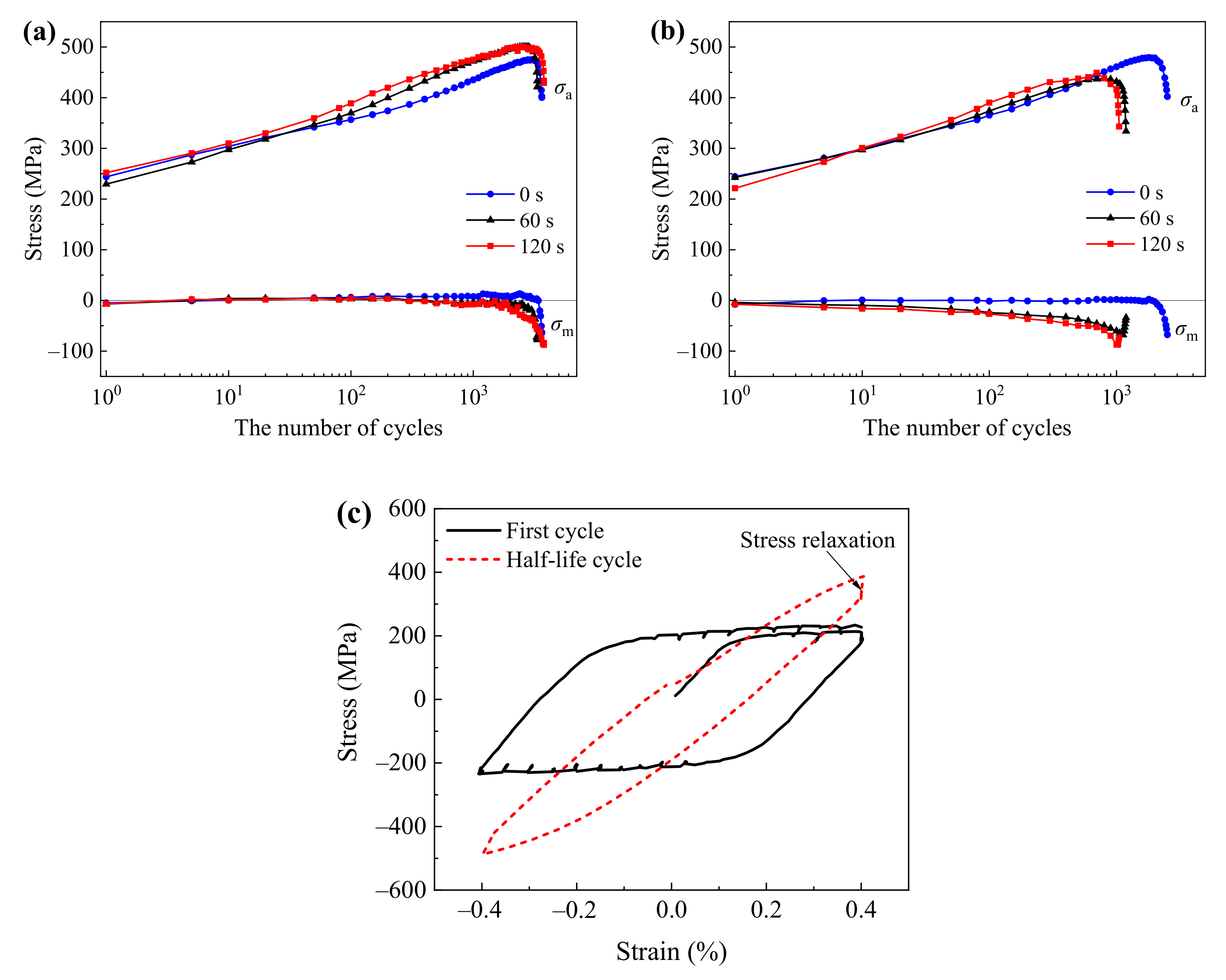
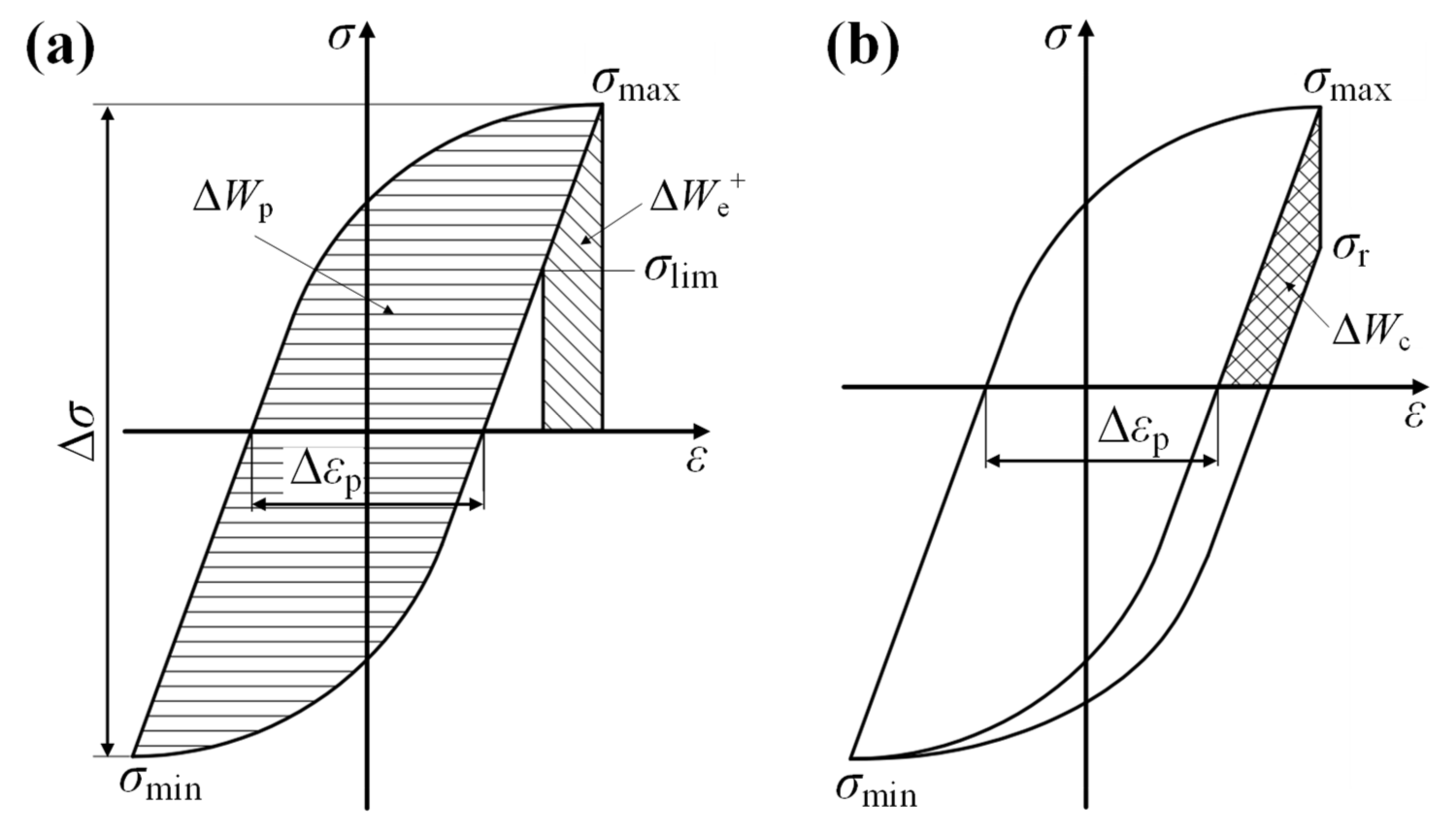
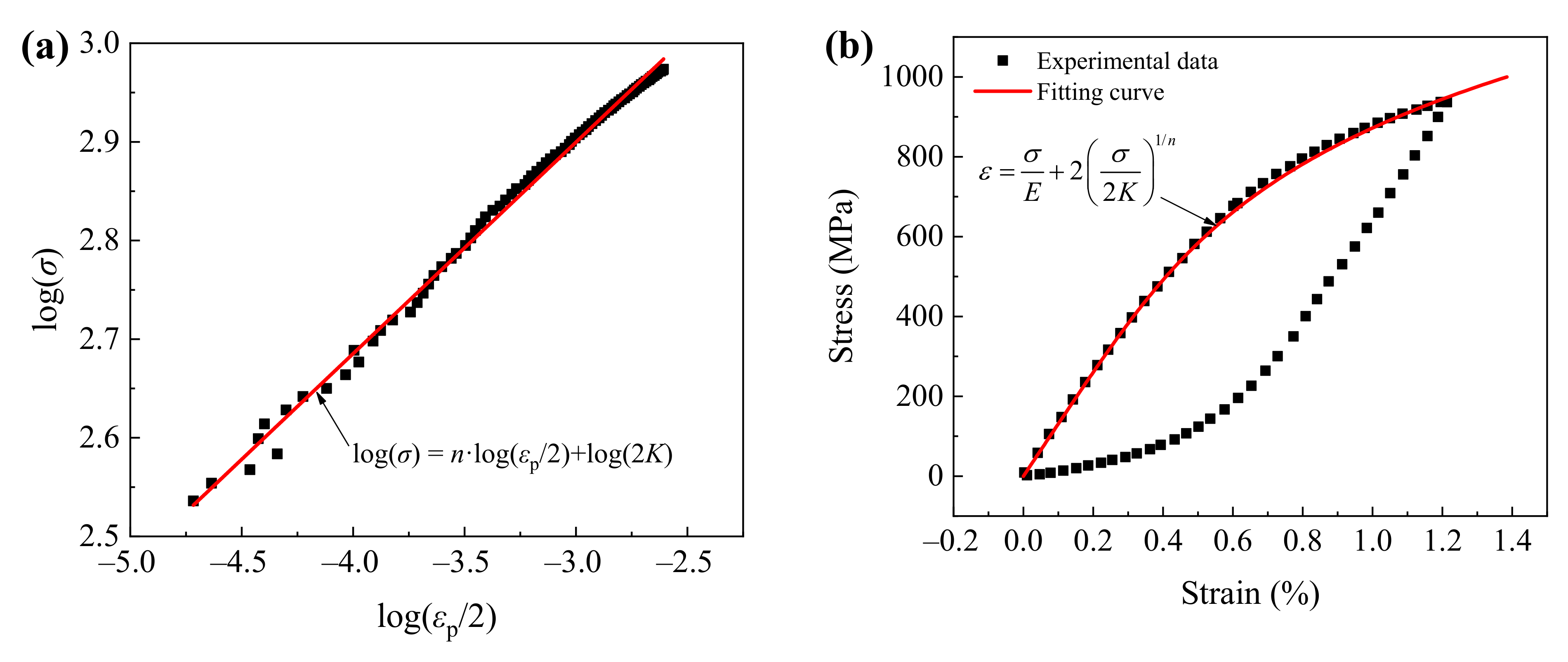
3.1. Cyclic Stress Responses

The cyclic stress amplitude response curves of Inconel 625 alloy with the strain rate of 2 × 10⁻³ s−1 at 700 °C and 800 °C are presented in Figure 4a,b, respectively. Inconel 625 alloy exhibited continuous cyclic hardening at 700 °C. After reaching the maximum, the cyclic stress amplitude decreased rapidly due to macro-crack propagation (Figure 4a). Similar continuous cyclic hardening for the large strain amplitudes at 800 °C was also observed, whereas a cyclic stress saturation behavior was found for the low strain amplitudes (Δε/2 ≤ 0.25%). The saturation was particularly evident at the strain amplitude of 0.2%, as shown in Figure 4b. In addition, the cyclic hardening level increased gradually with the strain amplitude. Figure 4c,d illustrate the half-life hysteresis loops under different strain amplitudes at 700 °C and 800 °C, respectively. It shows that the area of the half-life hysteresis loop was positively correlated with the applied strain amplitude.
Figure 5 describes the variation in cyclic stress amplitude curves for different strain rates. The cyclic stress amplitude curve decreased with the strain rate, indicating the negative strain rate sensitivity of Inconel 625 alloy. Meanwhile, the fatigue life increased with the strain rate. In general, the cyclic stress response of the alloy at high temperatures is closely related to the secondary precipitates. It is discussed in the subsequent section. As shown in Figure 6, the serration of the hysteresis loops can be observed at the beginning of fatigue under the lowest strain rate of 1.6 × 10⁻⁴ s−1, but it started to disappear at certain loading cycles. In Figure 6a, the serration did not exist on the hysteresis loop at the 230th cycle. The serration of hysteretic loops under larger strain rates was relatively weak and disappeared quickly (not shown here).
Figure 7a,b represent the evolution of cyclic stress amplitude (σa) and mean stress (σm) of the tests with different tensile-hold times. The cyclic stress amplitude curve under creep–fatigue conditions was higher than that under continuous fatigue (th = 0). Moreover, the mean stress was negative and gradually decreased until the rapid growth of fatigue cracks. The phenomenon of the negative mean stress was attributed to creep. During the tensile-hold period, a recovery effect similar to the slow recovery of crystal structure occurs in the alloy, which is macroscopically manifested as stress relaxation, resulting in the presence of negative mean stress [25,26]. As shown in Figure 7c, significant stress relaxation was observed in the first and half-life hysteresis loops of the C–F test (th = 120 s) at 800 °C. A more pronounced negative mean stress evolution can be seen at 800 °C than that at 700 °C, indicating a stronger creep–fatigue interaction during the tensile-hold period at 800 °C.

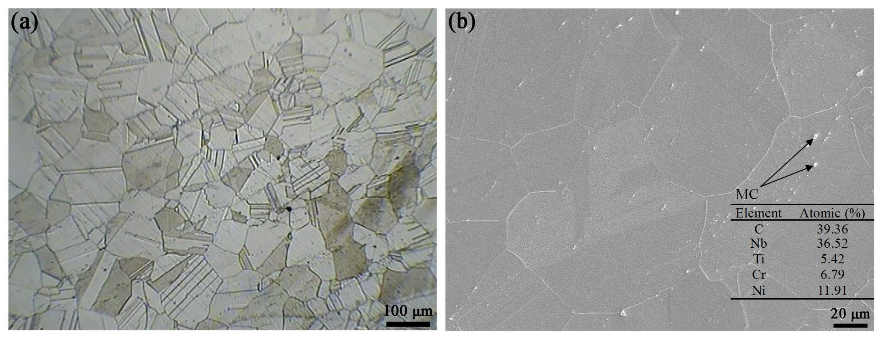
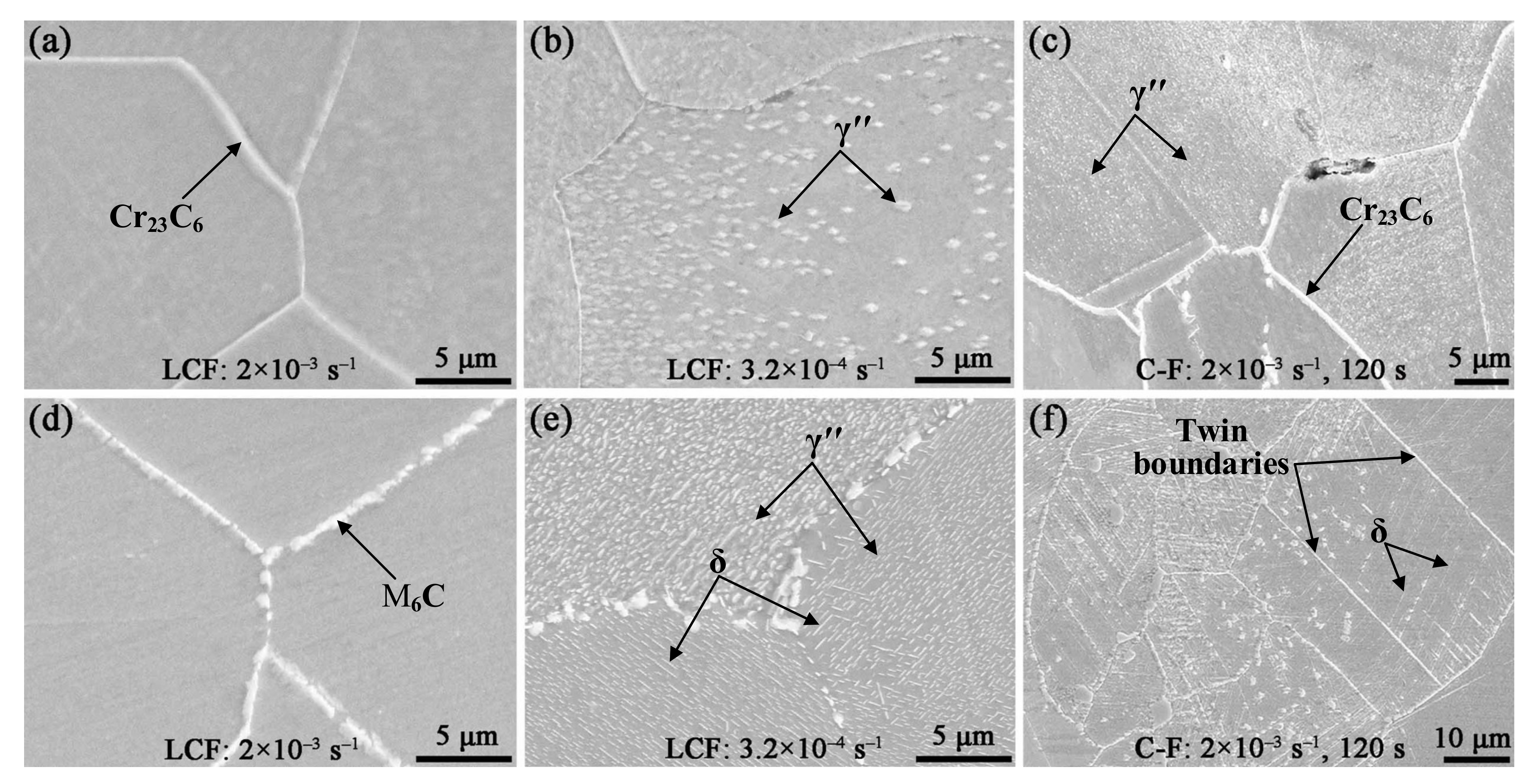
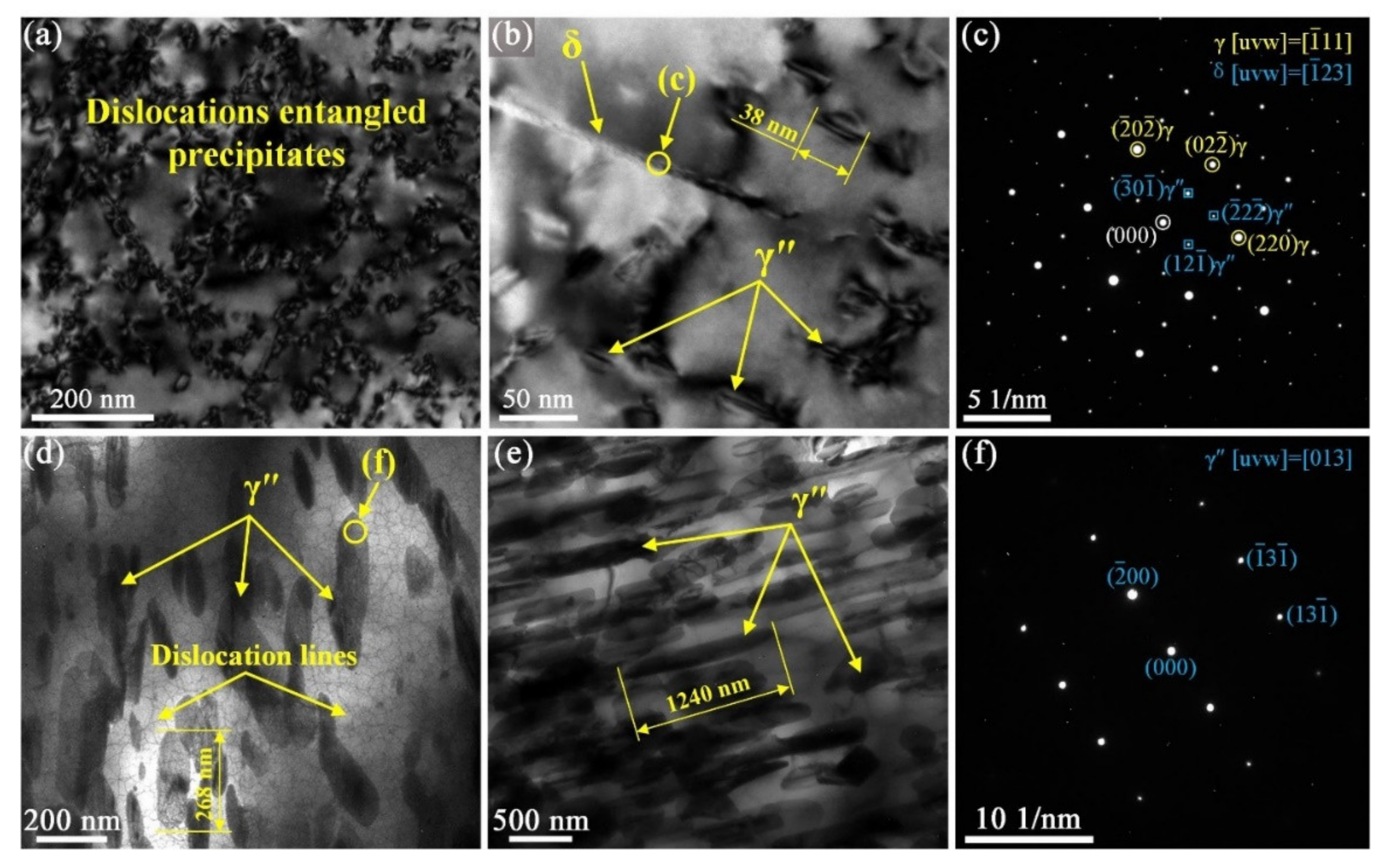
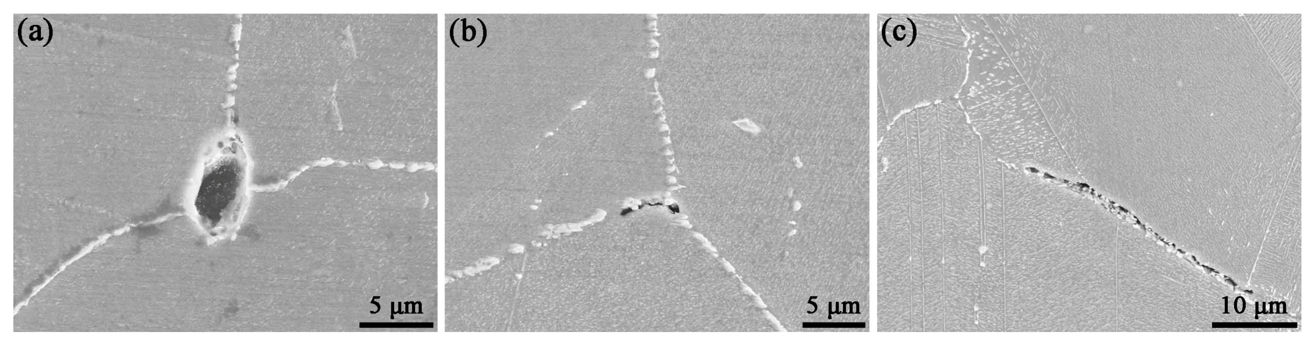
3.2. Microstructural Analysis

Figure 8 shows the SEM images of the longitudinal sections of the fatigue-fractured specimens. A few M23C6-type secondary carbides with the main metallic element of Cr were precipitated along grain boundaries at 700 °C [17,18]. The number of the Cr23C6 precipitates in the C–F specimen was significantly more than that in the LCF specimen (Figure 8c). Actually, the precipitation of Cr23C6 is not only affected by temperature and holding time, but also by the stress state. The longer tensile-hold state is more favorable to the diffusion of Cr atoms from the incoherent matrix toward a grain boundary, thus promoting the precipitation of Cr23C6 [27]. Furthermore, dispersed granular γ″ precipitates were observed in some grains of the LCF specimens under lower strain rates (Figure 8b) and the C–F specimens (Figure 8c) at 700 °C.
The precipitation of secondary carbides at 800 °C was more obvious than that at 700 °C. The continuously distributed granular carbides resulted in grain boundaries coarsening, as shown in Figure 8a–d. As stated in the Introduction part, the secondary carbides in Inconel 625 alloy at 800 °C were M23C6 and M6C, especially M23C6 [17]. In addition to the granular or lenticular γ″ phases, the needle-like δ phase was also found in the LCF specimens under low strain rates (Figure 8e) and in the C–F specimens (Figure 8f) at 800 °C.
The precipitates were seldom observed by SEM in the fatigue specimens under the strain rate of 2 × 10⁻³ s−1. However, fine precipitates, as well as dislocations-entangled precipitates, were found by TEM, as shown in Figure 9a–c. Moreover, Figure 9d,e illustrate the precipitate morphology in the fractured specimens of the LCF test ( ε ˙ = 3.2 × 10⁻⁴ s−1) and C–F test (th = 60 s) at 800 °C, respectively. The sizes of γ″ precipitates in Figure 9d,e were about 7.1 and 32.6 times larger than those in Figure 9b, respectively. It can be seen from the electron diffraction patterns in Figure 9 that the granular and lenticular precipitates were identified as the γ″ phase, and the needle-like precipitates were the δ phase.
Extensive isothermal aging studies on Inconel 625 alloy has shown that γ″ and δ phases can be precipitated directly from the matrix at 800 °C [2,8,17,18,19,20,21,22]. In the present study, the density of the γ″ phase was much greater than that of the δ phase in the fatigue-fractured specimens at 800 °C. This suggests that the γ″ precipitation was sensitive to cyclic deformation at high temperatures. As Mataveli et al. [2] reported, the γ″ nucleation was related to the plastic deformation. It was reasonable to assume that the dislocation substructures generated by cyclic plastic deformation provided nucleation sites for the γ″ phase, and the plastic deformation also facilitated atomic diffusion, thereby promoting the growth of the γ″ phases [28]. The precipitates were gradually nucleated, coarsened, and entangled with the dislocations during cyclic loading. Meanwhile, the precipitate–dislocation interaction could stabilize the dislocation substructures and prevent dislocation recovery, resulting in cyclic hardening of Inconel 625 alloy. Therefore, the precipitation of the γ″ phase during cyclic loading could be considered as the main reason for the continuous cyclic hardening of Inconel 625 alloy. It should be noted that the δ phase also has a precipitation strengthening effect, although its intensity is much smaller than that of the γ″ phase [17]. As the small cyclic plastic deformation had little contribution to γ″ precipitation, the cyclic response behavior was mainly controlled by dislocation density and slip bands. As the dislocation density and slip bands were easy to stabilize under small cyclic deformation, the saturation of the cyclic stress for the fatigue specimens under low strain amplitudes at 800 °C can be realized [29,30].
Similarly, the γ″ precipitate was also the primary cause of the negative strain rate sensitivity for Inconel 625 alloy at 700–800 °C. The decrease in strain rate ensured more time for the precipitation of the γ″ phase during each cycle. In order to accomplish the equivalent deformation in the fatigue test under the strain-controlled mode, the greater resistance caused by the precipitate–dislocation interaction had to be overcome, thereby increasing the cyclic stress amplitude.

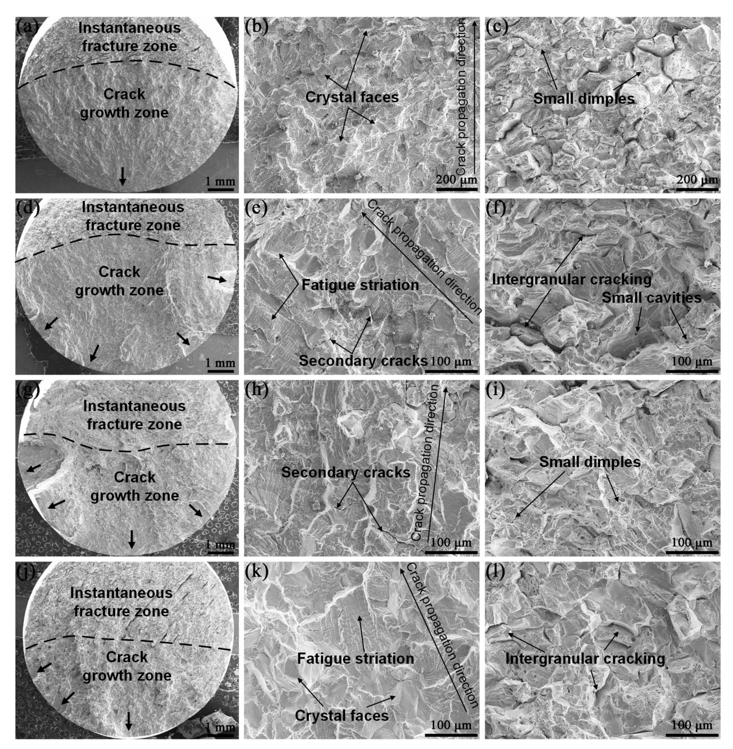
3.3. Fatigue Fractographic Analysis

Figure 10 shows the fatigue fracture morphology at 700 °C, including the crack initiation sites, the crack growth zone, and the instantaneous fracture zone. The cracks were initiated from the specimen surface. The specimen under the strain amplitude of 0.25% had only one crack source. The mode of crack nucleation changed from a single-source mode to a multiple-source mode with the increase in the strain amplitude. Subsequently, the cracks propagated transgranularly, and the typical fatigue striations were observed (Figure 10b,e,h,k). The crack growth zone became relatively flat after merging into the main crack by forming tearing edges. Dimples of different sizes can be found in the instantaneous fracture zones, and the larger dimples were accompanied by the cavities at the bottom (Figure 10c,f,i,l). Furthermore, the strain rate and the tensile-hold time seemed to have no effect on the fatigue fracture morphology at 700 °C, except for a small number of secondary cracks observed in the crack growth zone of the C–F fractured specimen.
Figure 11 represents the fatigue fracture morphology at 800 °C. In addition to fatigue striations, crystal faces and secondary cracks could also be seen in the crack growth zone (Figure 11b,e,h). The cracks propagated transgranularly in the beginning, then gradually grew in a mixed transgranular-intergranular mode. Additionally, the instantaneous fracture zone was characterized by intergranular ductile fracture, with fine dimples and voids on the fractured grains (Figure 11c,f,i). Comparing the instantaneous fracture morphologies of the fatigue specimens at 700 °C and 800 °C, it can be seen that the grain boundary strength of the specimens decreased significantly after fatigue loading at 800 °C. It is evident from Figure 11 that the strain rate and the tensile-hold time had a certain influence on the fracture morphologies at 800 °C. The fracture surface of the LCF-fractured specimen was rough and oxidized seriously under the lower strain rate (3.2 × 10⁻⁴ s−1) at 800 °C (Figure 11g–i). The crystal faces and secondary cracks were more apparent. Furthermore, the fracture surface of the C–F specimen (th = 60 s) at 800 °C was characterized by intergranular cracking (Figure 11j–l). Numerous crystal faces and secondary cracks, as well as a few oxidized fatigue striations, were observed in the crack growth zone.
Figure 12 displays the surface damage of the fractured samples at 800 °C. A continuous oxide scale was formed on the specimen surface as a result of high-temperature oxidation. Additionally, tiny voids at the alloy/scale interface were observed, as shown in Figure 12a,b. Gorman et al. [31] also found this kind of void in the Inconel 625 exposed at 750 °C. They noted that the voids were caused by the condensation of vacancies that occur as chromium diffuses toward the surface. It is believed that cyclic loading enhances the oxidation kinetics of alloy, thus leading to premature formation of the voids at the alloy/scale interface [32]. Therefore, these voids may be the priority sites where fatigue cracks were initiated due to stress concentration (Figure 12b). It can be seen from Figure 5b that the crack initiation lives under small strain rates were significantly lower than those under the large strain rate.
An oxide layer was observed on the crack flanks as a result of the lower loading strain rate (Figure 12c). Additionally, the cyclic stress amplitude in the crack propagation stage dropped faster under lower strain rates (Figure 5b), indicating that the oxidation also accelerated the crack propagation. Previous studies have shown that the influence of oxidation on crack propagation were complicated, mainly involving the oxidation-induced crack closure (OICC) mechanism and dynamic embrittlement [33,34]. OICC is associated with the oxide layer on the crack flanks, which reduces the driving force and the effective stress intensity factor. Hence, the crack propagation rate is reduced. Dynamic embrittlement is caused by oxygen diffusing into the grain boundary ahead of the crack tip, reducing grain boundary cohesion and enhancing intergranular cracking [35]. According to the observed fracture morphology (Figure 11), the increase in the crack growth rate of Inconel 625 under lower strain rates at 800 °C was attributed to dynamic embrittlement. This is consistent with the studies of crack propagation for Inconel 625 at 750 °C by Ozawa et al. [19].
The micro-voids and micro-cracks caused by creep were observed at grain boundaries or the triple-junction grain boundaries in the C–F specimens at 800 °C, as shown in Figure 13. In addition to creep damage, the oxidation damage also played an important role under the C–F condition at 800 °C. The oxygen diffusion along the grain boundaries accelerated during the tensile-hold period, resulting in severely oxidized and branched intergranular cracks (Figure 12d) [36]. The creep–fatigue–oxidation interaction damage significantly reduced the fatigue life, as shown in Figure 7b. Compared with the LCF life at 800 °C, the C–F lives with the hold time of 60 s and 120 s were reduced by 51.88% and 57.68%, respectively. In general, the creep damage resulted in the nucleation of micro-voids and micro-cracks at grain boundaries. The grain boundaries containing the surface creep micro-cracks could be degraded seriously by high-temperature oxidation, promoting the occurrence of surface intergranular cracking.

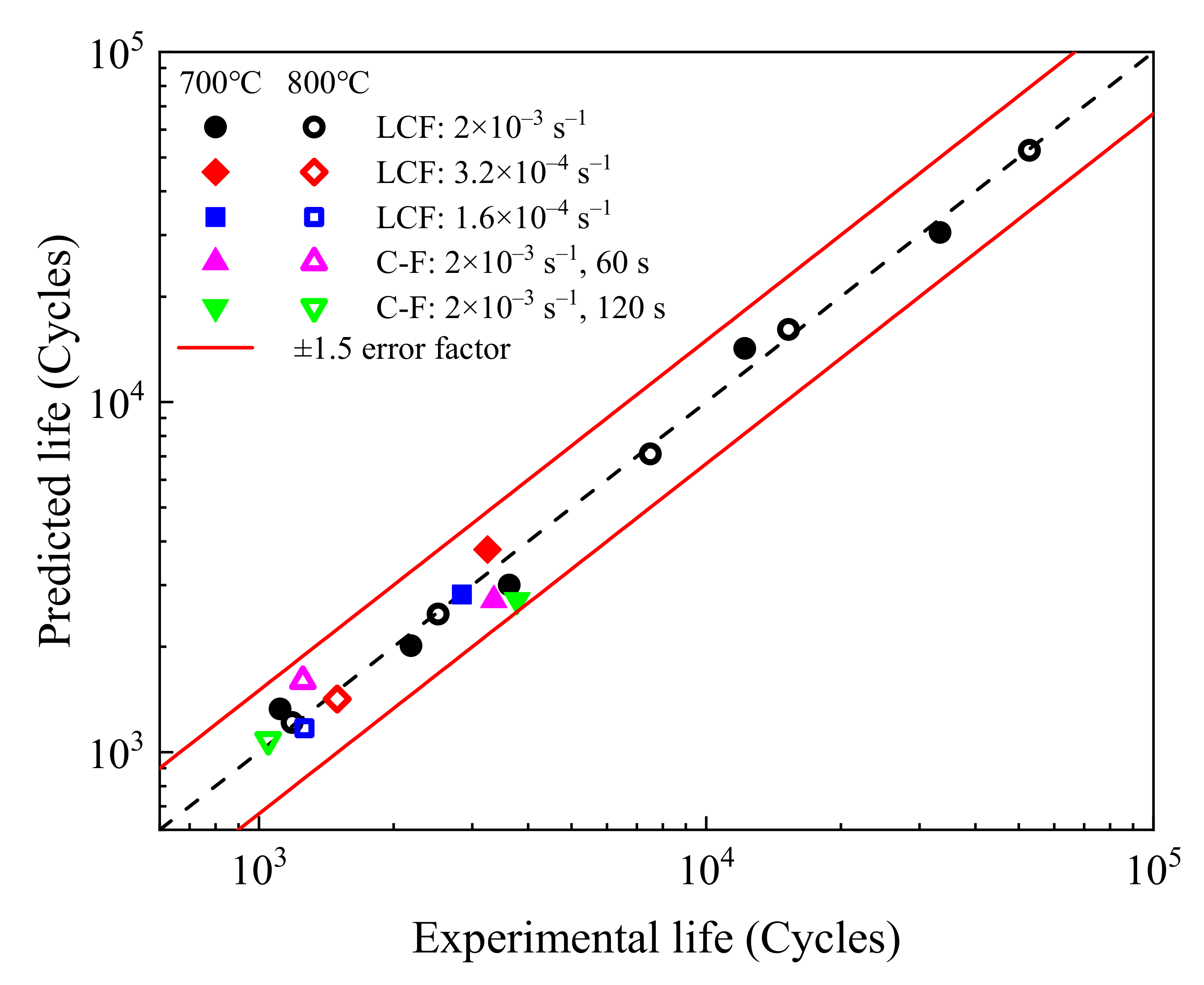
3.4. Life Prediction

The high-temperature fatigue life of Inconel 625 alloy was predicted using a frequency-modified total strain energy density model [37,38,39,40,41,42]. The cyclic frequency (fc) is introduced to modify the total strain energy density model in order to account for the effect of oxidative damage on fatigue life. The relationship between the failure life denoted by Nf and the frequency-modified total strain energy density can be expressed as follows:
N f = C f c α Δ W t β
Δ W t = Δ W p + Δ W e + + Δ W c
where C, α, and β are material constants, the cyclic frequency fc = 1/tc, and ΔWt is the total strain energy density of the half-life hysteresis loop. ΔWt is the sum of plastic strain energy density (ΔWp), elastic strain energy density (ΔWe+), and creep strain energy density (ΔWc), as shown in Figure 14.
The formula for ΔWp for Inconel 625 alloy is expressed as follows:
Δ W p = 1 n 1 + n ( Δ σ δ σ 0 ) Δ ε p + δ σ 0 Δ ε p
δ σ 0 = Δ σ 2 K Δ ε p 2 n
where K and n are material constants, which can be obtained by fitting the tensile part of the hysteresis loop under the maximum strain amplitude [43] (Figure 15). Figure 15a illustrates the identification method of K and n using the least squares method. As shown in Figure 15b, the tensile part of the half-life hysteresis loop under the strain amplitude of 0.6% at 700 °C was well fitted.
To improve the prediction accuracy of fatigue lives under small plastic deformations, the elastic strain energy density cannot be ignored [41]. The ΔWe+ shown in Figure 14a is the tensile elastic strain energy density considering the fatigue limit (σlim), which can be expressed as:
Δ W e + = σ max 2 σ lim 2 2 E
where E is the Young’s modulus. The σlim is 250 MPa for 700 °C and 310 MPa for 800 °C according to the data provided by Special Metals Corporation [44]. ΔWc defined as the creep strain energy density can be calculated as following:
Δ W c = σ max 2 σ r 2 2 E
where σr is the stress at the end of the hold time. The σr values of the C–F tests at 700 °C are 446.9 MPa (th = 60 s) and 504.8 MPa (th = 120 s), and those of the C–F tests at 800 °C are 321.4 MPa (th = 60 s) and 332.9 MPa (th = 120 s).
After obtaining ∆Wt for each test, the material constants in Equation (1) can be determined by the least squares method. First, plotting log(Nf) vs. log(fc) for different strain rates allows the identification of α from the slope. Then, β and C can be determined from the slope and the y-axis intercept, respectively, by plotting log(Nf·fcα) vs. log(∆Wt). The model parameters for Inconel 625 alloy are listed in Table 3. Figure 16 describes the prediction results by using the frequency-modified total strain energy density model. It can be seen that the predicted life is within the 1.5 times error band, indicating the model has high prediction accuracy.

4. Conclusions

The high-temperature fatigue behavior and damage mechanism for Inconel 625 alloy at 700 °C and 800 °C were investigated, and the following conclusions can be drawn:
(1) Inconel 625 alloy exhibited a continuous cyclic hardening under strain amplitudes of 0.25–0.6% at 700 °C and 0.3–0.5% at 800 °C, with a cyclic saturation under strain amplitudes of 0.2–0.25% at 800 °C. The cyclic stress responses under both temperatures showed the negative strain rate sensitivity, which is attributed to the precipitation of the γ″ phase.
(2) The fatigue failures at 700 °C under all test conditions occurred with a transgranular fracture mode. The fatigue failures at 800 °C under continuous fatigue conditions occurred with a transgranular-intergranular hybrid fracture manner, while intergranular cracking was found under creep–fatigue interaction conditions.
(3) The tiny voids at the alloy/scale interface caused by the high-temperature oxidation were crack initiation sites due to stress concentration, thus reducing the crack initiation life. Additionally, the creep–fatigue–oxidation interaction led to the grain boundary damages as well as the severely oxidized and branched intergranular cracks.
(4) A frequency-modified total strain energy density model was proposed to consider the effects of creep and oxidation on fatigue life, and the predicted fatigue lives were located within the 1.5 times error band.

Author Contributions

Conceptualization, X.C. and Z.F.; funding acquisition, Y.Z. and J.D.; investigation, Z.W. and Y.Z.; methodology, Z.W. and X.C.; supervision, J.D.; validation, Z.F. and Y.Z.; writing—original draft, Z.W.; writing—review and editing, X.C. and Y.Z. All authors have read and agreed to the published version of the manuscript.

Funding

This work was supported by the National Key Research and Development Project of China (No. 2016YFC0801902), the Anhui Provincial Key Research and Development Program (No. 202004a05020005), the Anhui Provincial Natural Science Foundation (No. 1908085J16), and the SINOMACH Science and Technology Major Project (No. SINOMAST-ZDZX-2018-05).

Data Availability Statement

Not applicable.

Conflicts of Interest

The authors declare no conflict of interest.

References

  1. Shoemaker, L.E. Alloys 625 and 725: Trends in properties and applications. In Superalloys 718, 625, 706 and Derivatives 2005; Loria, E.A., Ed.; The Minerals, Metals & Materials Society: Warrendale, PA, USA, 2005; pp. 409–418. Available online: https://www.tms.org/Superalloys/10.7449/2005/Superalloys_2005_409_418.pdf (accessed on 5 March 2021).
  2. Mataveli Suave, L.; Cormier, J.; Villechaise, P.; Soula, A.; Hervier, Z.; Bertheau, D.; Laigo, J. Microstructural evolutions during thermal aging of Alloy 625: Impact of temperature and forming process. Metall. Mater. Trans. A 2014, 45, 2963–2982. [Google Scholar] [CrossRef]
  3. Singh, J.B.; Chakravartty, J.K.; Sundararaman, M. Work hardening behaviour of service aged Alloy 625. Mater. Sci. Eng. A 2013, 576, 239–242. [Google Scholar] [CrossRef]
  4. Cinoglu, I.S.; Charbal, A.; Vermaak, N. Towards exploiting inelastic design for Inconel 625 under short-term cyclic loading at 600 °C. Mech. Mater. 2020, 140, 103219. [Google Scholar] [CrossRef]
  5. Wang, Y.; Wang, B.; Chen, L. High-temperature low-cycle fatigue behavior of 625 nickel-base superalloy welding joint. Appl. Mech. Mater. 2014, 618, 120–124. [Google Scholar] [CrossRef]
  6. Bui-Quoc, T.; Gomuc, R.; Biron, A.; Nguyen, H.; Masounave, J. Elevated temperature fatigue-creep behavior of nickel-base superalloy IN 625. In Low Cycle Fatigue; Solomon, G.H.H., Kaisand, L., Leis, B., Eds.; ASTM International: West Conshohocken, PA, USA, 1988; pp. 470–484. [Google Scholar]
  7. Evans, N.D.; Maziasz, P.J.; Shingledecker, J.P.; Yamamoto, Y. Microstructure evolution of alloy 625 foil and sheet during creep at 750 °C. Mater. Sci. Eng. A 2008, 498, 412–420. [Google Scholar] [CrossRef]
  8. Mathew, M.; Palanichamy, P.; Latha, S.; Jayakumar, T.; Rao, K.B.S.; Mannan, S.; Raj, B. Microstructural changes in alloy 625 due to creep and characterization using NDE techniques. Indian Met. 2010, 63, 449–452. [Google Scholar] [CrossRef]
  9. Mataveli Suave, L.; Cormier, J.; Bertheau, D.; Villechaise, P.; Soula, A.; Hervier, Z.; Hamon, F. High temperature low cycle fatigue properties of alloy 625. Mater. Sci. Eng. A 2016, 650, 161–170. [Google Scholar] [CrossRef]
  10. Yin, J.; Zheng, Q.; Peng, Z.; Zhang, X. Review of supercritical CO2 power cycles integrated with CSP. Int. J. Energy Res. 2019, 44, 1337–1369. [Google Scholar] [CrossRef]
  11. Ho, C.K. Advances in central receivers for concentrating solar applications. Sol. Energy 2017, 152, 38–56. [Google Scholar] [CrossRef]
  12. Ortega, J.; Khivsara, S.; Christian, J.; Ho, C.; Dutta, P. Coupled modeling of a directly heated tubular solar receiver for supercritical carbon dioxide Brayton cycle: Structural and creep-fatigue evaluation. Appl. Therm. Eng. 2016, 109, 979–987. [Google Scholar] [CrossRef] [Green Version]
  13. McMurtrey, M.D.; Rupp, R.E.; Barua, B.; Messner, M. Creep-Fatigue Behavior and Damage Accumulation of A Candidate Structural Material for Concentrating Solar Power Solar Thermal Receiver (Final Technical Report); Idaho National Lab.(INL): Idaho Falls, ID, USA, 2021. [Google Scholar] [CrossRef]
  14. Sarvghad, M.; Delkasar Maher, S.; Collard, D.; Tassan, M.; Will, G.; Steinberg, T.A. Materials compatibility for the next generation of Concentrated Solar Power plants. Energy Storage Mater. 2018, 14, 179–198. [Google Scholar] [CrossRef]
  15. Laporte-Azcué, M.; González-Gómez, P.A.; Rodríguez-Sánchez, M.R.; Santana, D. Material selection for solar central receiver tubes. Sol. Energy Mater. Sol. Cells 2021, 231, 111317. [Google Scholar] [CrossRef]
  16. Purohit, A.; O’Donnell, J.E.; Thiele, U. Fatigue strength and evaluation of creep damage during fatigue cycling of inconel Alloy 625. In American Nuclear Society Winter Meeting; Transactions of the American Nuclear Society: San Francisco, CA, USA, 1983; pp. 1–4. Available online: https://www.osti.gov/biblio/5906535 (accessed on 5 March 2021).
  17. Moore, I.J.; Taylor, J.I.; Tracy, M.W.; Burke, M.G.; Palmiere, E.J. Grain coarsening behaviour of solution annealed Alloy 625 between 600–800 °C. Mater. Sci. Eng. A 2017, 682, 402–409. [Google Scholar] [CrossRef]
  18. Floreen, S.; Fuchs, G.E.; Yang, W. The Metallurgy of Alloy 625. In Superalloys 718, 625, 706 and Various Derivatives; Loria, E.A., Ed.; The Minerals, Metals & Materials Society: Pittsburgh, PA, USA, 1994; pp. 13–37. Available online: https://www.tms.org/superalloys/10.7449/1994/Superalloys_1994_13_37.pdf (accessed on 5 March 2021).
  19. Ozawa, Y.; Ishikawa, T.; Takeda, Y. Characterization of crack tip damage zone formation on alloy 625 during fatigue crack growth at 750 °C by transmission EBSD method. In ASME 2017 Power Conference Joint With ICOPE-17; ASME: Charlotte, NC, USA, 2017; pp. 1–7. [Google Scholar] [CrossRef]
  20. Mathew, M.D.; Parameswaran, P.; Bhanu, S.R.K. Microstructural changes in alloy 625 during high temperature creep. Mater. Charact. 2008, 59, 508–513. [Google Scholar] [CrossRef]
  21. Liu, D.; Zhang, X.; Qina, X.; Ding, Y. High-temperature mechanical properties of Inconel-625: Role of carbides and delta phase. Mater. Sci. Technol. 2017, 33, 1610–1617. [Google Scholar] [CrossRef]
  22. Chakravartty, J.K.; Singh, J.B.; Sundararaman, M. Microstructural and mechanical properties of service exposed Alloy 625 ammonia cracker tube removed after 100,000 h. Mater. Sci. Technol. 2013, 28, 702–710. [Google Scholar] [CrossRef]
  23. Kohler, M. Effect of the elevated-temperature-precipitation in alloy 625 on properties and microstructure. In Superalloys 718, 625 and Various Derivatives; Loria, E.A., Ed.; The Minerals, Metals & Materials Society: Pittsburgh, PA, USA, 1991; pp. 363–374. Available online: https://www.tms.org/Superalloys/10.7449/1991/Superalloys_1991_363_374.pdf (accessed on 5 March 2021).
  24. Shankar, V.; Rao, K.B.S.; Mannan, S.L. Microstructure and mechanical properties of Inconel 625 superalloy. J. Nucl. Mater. 2001, 288, 222–232. [Google Scholar] [CrossRef]
  25. Rodriguez, P.; Rao, K.B.S. Nucleation and growth of cracks and cavities under creep-fatigue interaction. Prog. Mater. Sci. 1993, 37, 403–480. [Google Scholar] [CrossRef]
  26. Barrett, P.R.; Ahmed, R.; Menon, M.; Hassan, T. Isothermal low-cycle fatigue and fatigue-creep of Haynes 230. Int. J. Solids Struct. 2016, 88–89, 146–164. [Google Scholar] [CrossRef]
  27. He, L.; Zheng, Q.; Sun, X.; Hou, G.; Guan, H.; Hu, Z. M23C6 precipitation behavior in a Ni-base superalloy M963. J. Mater. Sci. 2005, 40, 2959–2964. [Google Scholar] [CrossRef]
  28. Li, H.; Jing, H.; Xu, L.; Han, Y.; Zhao, L.; Yang, S.; Tang, Z. Effect of strain rate induced M23C6 distribution on cyclic deformation behavior: Cyclic hardening model. Int. J. Plast. 2020, 127, 102634. [Google Scholar] [CrossRef]
  29. Zhang, P.; Zhu, Q.; Hu, C.; Wang, C.; Chen, G.; Qin, H. Cyclic deformation behavior of a nickel-base superalloy under fatigue loading. Mater Des. 2015, 69, 12–21. [Google Scholar] [CrossRef]
  30. Rahmani, K.; Nategh, S. Low cycle fatigue mechanism of René 80 at high temperature-high strain. Mater. Sci. Eng. A 2008, 494, 385–390. [Google Scholar] [CrossRef]
  31. Gorman, D.M.; Higginson, R.L.; Du, H.; McColvin, G.; Fry, A.T.; Thomson, R.C. Microstructural analysis of IN617 and IN625 oxidised in the presence of steam for use in ultra-supercritical power plant. Oxid. Met. 2012, 79, 553–566. [Google Scholar] [CrossRef] [Green Version]
  32. Moulin, G.; Arevalo, P.; Salleo, A. Influence of external mechanical loadings (creep, fatigue) on oxygen diffusion during nickel oxidation. Oxid. Met. 1996, 45, 153–181. [Google Scholar] [CrossRef]
  33. He, X.; Zhang, Y.; Shi, H.; Gu, J.; Li, C.; Kadau, K.; Luesebrink, O. Influence of orientation and temperature on the fatigue crack growth of a nickel-based directionally solidified superalloy. Mater. Sci. Eng. A 2014, 618, 153–160. [Google Scholar] [CrossRef]
  34. Christ, H.J.; Wackerman, K.; Krupp, U. On the mechanism of dynamic embrittlement and its effect on fatigue crack propagation in IN718 at 650 °C. Procedia Struct. Integr. 2016, 2, 557–564. [Google Scholar] [CrossRef]
  35. Kitaguchi, H.; Li, H.; Evans, H.; Ding, R.; Jones, I.; Baxter, G.; Bowen, P. Oxidation ahead of a crack tip in an advanced Ni-based superalloy. Acta Mater. 2013, 61, 1968–1981. [Google Scholar] [CrossRef]
  36. Tong, J.; Dalby, S.; Byrne, J.; Henderson, M.; Hardy, M. Creep, fatigue and oxidation in crack growth in advanced nickel base superalloys. Int. J. Fatigue 2001, 23, 897–902. [Google Scholar] [CrossRef]
  37. Ding, B.; Ren, W.; Zhong, Y.; Yuan, X.; Peng, J.; Zheng, T.; Shen, Z.; Guo, Y.; Xuan, W.; Yu, J.; et al. Analysis of the fully-reversed creep-fatigue behavior with tensile-dwell periods of superalloy DZ445 at 900 °C. Eng. Fract. Mech. 2021, 250, 107781. [Google Scholar] [CrossRef]
  38. Ding, B.; Ren, W.; Peng, J.; Zheng, T.; Hou, L.; Yu, J.; Ren, Z.; Zhong, Y. Damage mechanism and life prediction based on tensile-stress- and compressive-stress-dominated low-cycle fatigue of a directionally solidified Ni-based superalloy DZ445. Mater. Sci. Eng. A 2019, 742, 478–492. [Google Scholar] [CrossRef]
  39. Barat, K.; Sivaprasad, S.; Kar, S.K.; Tarafder, S. Low-cycle fatigue of IN 718: Effect of waveform. Fatigue Fract. Eng. Mater. Struct. 2019, 42, 2823–2843. [Google Scholar] [CrossRef]
  40. Wang, Q.; Zhang, N.; Wang, X. A new 3D creep-fatigue-elasticity damage interaction diagram based on the total tensile strain energy density model. Metals 2020, 10, 274. [Google Scholar] [CrossRef] [Green Version]
  41. Zhu, S.; Yang, Y.; Huang, H.; Lv, Z.; Wang, H. A unified criterion for fatigue-creep life prediction of high temperature components. Proc. Inst. Mech. Eng. Part G J. Aerosp. Eng. 2016, 231, 677–688. [Google Scholar] [CrossRef]
  42. Benedetti, M.; Berto, F.; Le, B.L.; Santus, C. A novel strain-energy-density based fatigue criterion accounting for mean stress and plasticity effects on the medium-to-high-cycle uniaxial fatigue strength of plain and notched components. Int. J. Fatigue 2020, 133, 105397. [Google Scholar] [CrossRef]
  43. Mukherjee, S.; Barat, K.; Sivaprasad, S.; Tarafder, S.; Kar, S.K. Elevated temperature low cycle fatigue behaviour of Haynes 282 and its correlation with microstructure-effect of ageing conditions. Mater. Sci. Eng. A 2019, 762, 138073. [Google Scholar] [CrossRef]
  44. Special Metals Corporation. Available online: https://www.specialmetals.com/documents/ technical-bulletins/inconel/inconel-alloy-625.pdf (accessed on 5 March 2021).
Figure 1. Optical micrograph (a) and SEM (b) of the solid-solution heat-treated Inconel 625.
Metals 12 00755 g001
Figure 2. Geometry of the test specimen (dimensions in mm).
Metals 12 00755 g002
Figure 3. Illustration of the loading waveforms of (a) LCF test and (b) C–F test.
Metals 12 00755 g003
Figure 4. Cyclic stress amplitude response curves at (a) 700 °C and (b) 800 °C, and the half-life hysteresis loops at (c) 700 °C and (d) 800 °C.
Metals 12 00755 g004
Figure 5. Influence of strain rate on the cyclic stress amplitude response curves at (a) 700 °C and (b) 800 °C.
Metals 12 00755 g005
Figure 6. DSA effect reflected by hysteresis loops ( ε ˙ = 1.6 × 10⁻⁴ s−1) at (a) 700 °C and (b) 800 °C.
Metals 12 00755 g006
Figure 7. Cyclic stress response of the tests with different tensile-hold times at (a) 700 °C and (b) 800 °C, and (c) the hysteresis loops of C–F test (th = 120 s) at 800 °C.
Metals 12 00755 g007
Figure 8. Microstructures of the fractured specimens: (ac) 700 °C; (df) 800 °C.
Metals 12 00755 g008
Figure 9. TEM micrographs of the precipitates at 800 °C: (a,b) LCF with ε ˙ = 2 × 10⁻³ s−1; (d) LCF with ε ˙ = 3.2 × 10⁻⁴ s−1; (e) C–F with th = 60 s; (c,f) electron diffraction patterns in (b,d), respectively.
Metals 12 00755 g009
Figure 10. Fracture morphology of the specimens at 700 °C: (ac) with Δε/2 = 0.25%, ε ˙ = 2 × 10⁻³ s−1; (df) with Δε/2 = 0.4%, ε ˙ = 2 × 10⁻³ s−1; (gi) with Δε/2 = 0.4%, ε ˙ = 3.2 × 10⁻⁴ s−1; (jl) with Δε/2 = 0.4%, ε ˙ = 2 × 10⁻³ s−1, th = 60 s.
Metals 12 00755 g010
Figure 11. Fracture morphology of the specimens at 800 °C: (ac) with Δε/2 = 0.25%, ε ˙ = 2 × 10⁻³ s−1; (df) with Δε/2 = 0.4%, ε ˙ = 2 × 10⁻³ s−1; (gi) with Δε/2 = 0.4%, ε ˙ = 3.2×10⁻⁴ s−1; (jl) with Δε/2 = 0.4%, ε ˙ = 2 × 10⁻³ s−1, th = 60 s.
Metals 12 00755 g011
Figure 12. Surface damage of samples at 800 °C: (a) LCF with ε ˙ = 1.6 × 10⁻⁴ s−1, (b,c) LCF with ε ˙ = 3.2 × 10⁻⁴ s−1, and (d) C–F with th = 60 s.
Metals 12 00755 g012
Figure 13. Grain boundary damages of the sample under C–F test (th = 60 s) at 800 °C: (a) micro-void; (b,c) micro-cracks.
Metals 12 00755 g013
Figure 14. Hysteresis loop and strain energy density for (a) continuous fatigue and (b) fatigue with tensile-hold.
Metals 12 00755 g014
Figure 15. Identification method of K and n: (a) plot of log(σ) vs. log(εp/2), and (b) fitting result of the tensile part of the half-life hysteresis loop under the strain amplitude of 0.6% at 700 °C.
Metals 12 00755 g015
Figure 16. Comparison of predicted and experimental lives of Inconel 625 alloy.
Metals 12 00755 g016
Table 1. Chemical composition of Inconel 625 alloy (wt.%).
NiCrFeMoNb + TaMnSiPSAlTiCoC
59.622.74.938.053.280.1430.3190.0090.0060.1940.290.0670.035
Table 2. Test matrix for Inconel 625 alloy.
Temp. (°C)Test TypeStrain Rate
ε ˙ (s−1)
Stress Amplitude
ε/2
Hold Time
th (s)
Cycle Period
tc (s)
700LCF2 × 10−30.25%-5
0.3%-6
0.4%-8
0.5%-10
0.6%-12
3.2 × 10−40.4%-50
1.6 × 10⁻⁴-100
C–F2 × 10−30.4%6068
120128
800LCF2 × 10−30.2%-4
0.25%-5
0.3%-6
0.4%-8
0.5%-10
3.2 × 10−40.4%-50
1.6 × 10⁻⁴-100
C–F2 × 10−30.4%6068
120128
Table 3. Parameters of the life prediction model for Inconel 625 alloy.
Temp. (°C)E (GPa)K (MPa)nC (MPa)αβ
700151.630950.21854790.045−1.132
800149.326230.18461030.275−1.129
Publisher’s Note: MDPI stays neutral with regard to jurisdictional claims in published maps and institutional affiliations.

