Article

Investigation of Laser Butt Welding of AISI 304L and Q235 Steels Based on Numerical and Experimental Analyses

1
Guangdong Provincial Welding Engineering Technology Research Center, Guangdong University of Technology, Guangzhou 510006, China
2
Institute of Intelligent Manufacturing, Guangdong Academy of Sciences, Guangzhou 510070, China
3
Department of Mechanical Engineering, National University of Singapore, 21 Lower Kent Ridge Road, Singapore 119077, Singapore
*
Authors to whom correspondence should be addressed.
Metals 2022, 12(5), 803; https://doi.org/10.3390/met12050803
Submission received: 29 March 2022 / Revised: 29 April 2022 / Accepted: 2 May 2022 / Published: 6 May 2022
(This article belongs to the Section Welding and Joining)

Abstract

:
The fiber laser butt welding of AISI 304L and Q235 low-carbon steel is performed in this study. An integrated heat source combined with an asymmetric double-ellipsoidal heat source and a cylindrical heat source is designed to perform the numerical simulation of the laser butt welding process. With the established numerical simulation model, the formation of the welded joint is studied by investigating the thermal process. The effects of the laser power and laser beam offset to the sides of the center of the welding gap on the welded joint shape and strength are experimentally investigated, and the optimum laser power and laser beam offset are determined via tensile strength and hardness tests of the weldment. The numerical simulation results based on the asymmetric heat source agree well with the experimental results and are applied to investigate the mechanisms for forming different welded joint shapes in AISI 304L and Q235 steels. The different thermal conductivity and melting temperatures of the two dissimilar metals result in the different shapes of the welded joint.

1. Introduction

Dissimilar metal welding has attracted increasing attention in many fields, such as for use in nuclear reactors, power plants, and petrochemical equipment manufacturing [1,2,3], due to the high cost-savings related to the precious metals. Furthermore, more comprehensive characteristics of the weldment, not only in terms of resistance to corrosion but also the reduced of the heavy materials, can be acquired by performing dissimilar metal welding [4,5].
Joining dissimilar materials is more difficult and challenging than joining the same material, as dissimilar materials have different mechanical, physical, chemical, and metallurgical properties [6,7,8,9,10]. The main issue in welding dissimilar metal joints is the formation of thick intermetallic compound (IMC) layers [11,12]. The intermetallic compound layer is inevitable in dissimilar material welding and is necessary to achieve a reliable welded joint. However, if the intermetallic compound layer thickness is larger than a certain value, the brittleness of dissimilar metal joints will increase and the corresponding mechanical properties will deteriorate [13]. Therefore, it is a great concern to control the formation of IMCs and limit the IMC thickness in order to improve the mechanical properties of the welded joints [14,15]. A large number of studies have been performed to inhibit the growth of IMC layers during the welding of dissimilar metals [16,17,18]. These studies have revealed that precise control of the heat input during the welding process is the key factor, which is required to obtain ideal intermetallic compound layers.
With consideration of these limitations, the fiber laser is considered an ideal heating source for joining dissimilar metals, due to its high power density, low heat-affected zone, and precise control of the laser beam parameters (focus position, laser incident angle, beam diameter, etc.) [19,20,21], providing better control of the IMC layer formation and thickness. Bhanu et al. studied the characteristics of laser-welded dissimilar joints of 9Cr-1Mo-V-Nb (P91) steel and Incoloy 800HT austenitic nickel alloy and found that solidification cracks appeared in the weld fusion zone, confirming the susceptibility of Incoloy 800HT [22].
Some researchers have used laser welding–brazing for dissimilar metal joints [23,24,25]. The laser welding–brazing method helps control the mixture of dissimilar metals in the molten pool and prevents the formation of the brittle intermetallic compound layer, resulting in higher strength compared with other fusion welding processes. However, the joint strength in laser welding–brazing may be insufficient if the weld needs to be polished.
Laser beam welding (LBW) is being increasingly applied due to its high power density, low distortion level, and ease of installation [26,27,28,29]. Laser keyhole welding is an efficient welding method that is now widely used in the welding of dissimilar metals [30,31]. Gennari et al. studied the roles of weldability and plastic deformation in duplex stainless steel during laser beam welding and found that plastic deformation resulted in higher hardness of the base material [32]. Some researchers have conducted overlap welding experiments by placing an Al plate on steel plates, with the laser beam irradiating the Al plate [33]. They acquired good mechanical performance from the welded joints. Few studies have been performed on the laser welding of dissimilar metals with a butt welding configuration, as this requires accuracy during assembly, additional flux, and filler wires. The application of filler wires or additional flux results in certain improvements of the weld, but laser welding with filler materials is too difficult in industrial applications, as too many requirements and parameters are involved in the wire positioning, and this process also results in low efficiency and productivity [34,35,36,37]. Therefore, autogenous laser keyhole welding is expected to be applied in the dissimilar welding of AISI 304L stainless steel and Q235 low-alloy steel, which are the most common and popular metals applied in the manufacturing industry.
The numerical simulation approach is considered a powerful tool for analyzing the welding processes, revealing the mechanisms of metal fluid and thermal effects in the weld pool [38]. Cho et al. developed a numerical simulation method to explore the effects of the laser wavelength on the fusion shape during laser welding [39]. Jetro et al. presented a numerical model to study the melt flow down the keyhole front during fiber laser welding and provided explanations of the main liquid transport mechanisms within the keyhole [40]. Jiang et al. performed a numerical investigation involving the laser welding of high-strength steel, which agreed well with the experimental results [41]. Numerical simulation methods also play an important role in the laser welding of dissimilar alloys.
To promote the application of dissimilar welding, in this study the autogenous fiber laser butt welding of AISI 304L and Q235 steels is implemented. A numerical simulation model based on the combination of an asymmetric double-ellipsoidal heat source and a cylindrical heat source is established to investigate the thermal process of the welded joint. The formation of the different weld shapes in two different metals is explained by the thermal data extracted from the simulation. This study investigates the effects of the laser power and laser beam offset to the sides of the center of the weld gap on the welded joint shape and strength, and provides a better understanding of the fiber laser butt welding of AISI 304L and Q235 steels.

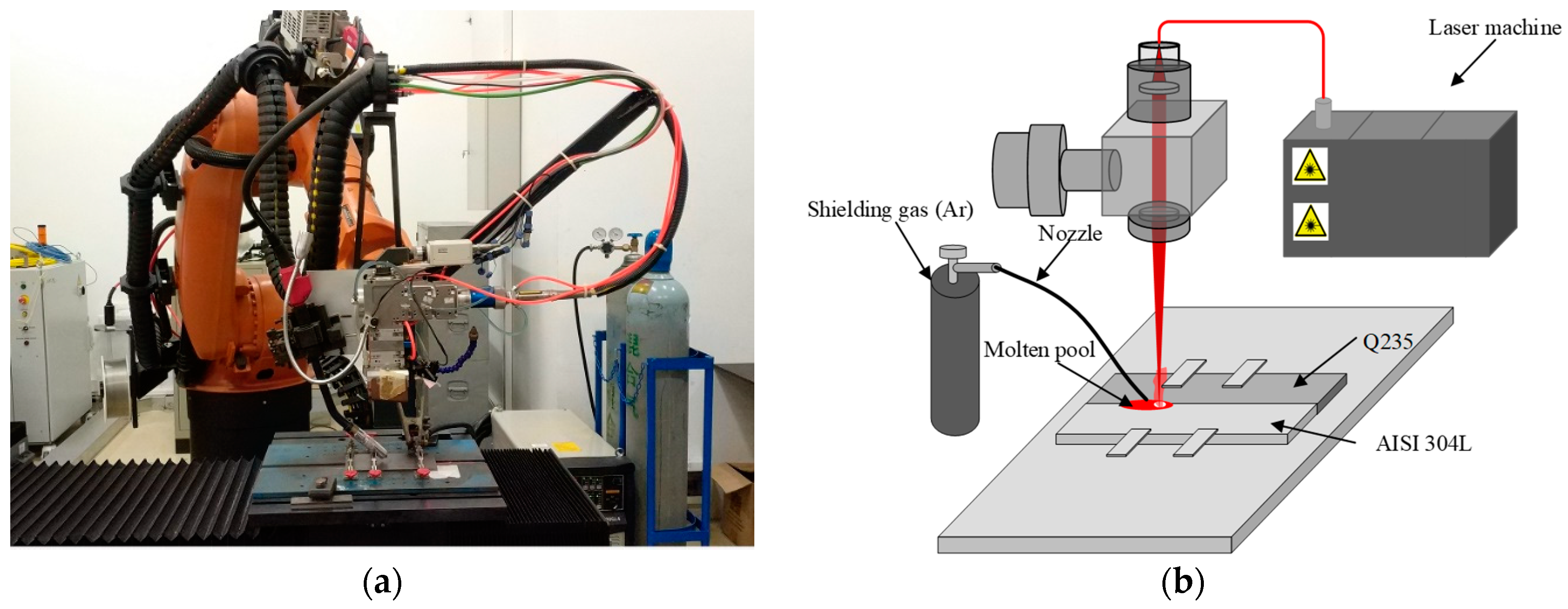
2. Experimental Setup

2.1. Laser Welding Setup

The welding experiments were carried out by applying a continuous fiber laser (Chuangxin laser MFMC6000) (Maxphotonics, Shenzhen, China) with a maximum output of 6 kW. The focal length of the laser head was 200 mm, and the diameter of the laser beam spot was 400 μm. The wavelength of the laser beam was 1080 nm. The focal position of the laser beam was 0 mm, and the welding speed was 0.06 m/s. The welding head was installed on a KUKA welding robot and equipped with an air-blowing protection device. The protection air was 99.99% argon gas with a shielding gas flow rate of 25 L/min. The laser welding system is shown in Figure 1. The laser beam was transmitted through a processing fiber with a diameter of 600 um, and the length of the fiber was 3 m. The workpieces of AISI 304 and Q235 steels were fixed by clamps to guarantee the gap between them was zero or less than 0.05 mm.
The effects of the laser beam power and the laser beam offset beside the gap between the AISI 304L stainless steel and Q235 low-carbon steel were investigated in this study, and the welding process parameters are listed in Table 1. The values of the offset were defined to be positive when the laser beam moved toward the Q235low-carbon steel and negative when the laser beam moved toward AISI 304L stainless steel.

2.2. Materials

The dimensions of the Q235 steel were 150 mm × 40 mm × 3 mm and the dimensions of AISI 304L stainless steel were 150 mm × 40 mm × 3 mm in this study. The chemical compositions of these two dissimilar materials are shown in Table 2.
The surfaces of specimens were cleaned with acetone in advance to avoid oil pollution. After welding, the samples were cut, ground, polished, and etched to observe their welded joints. The details of the welded cross-sections were measured from the optical micrographs.

3. Numerical Simulation Setup

3.1. Mesh Design and Assumptions in Numerical Simulation

The finite element analysis was applied in this study to numerically simulate the welding process. Finite element modeling of laser butt welding was conducted at ambient temperature (20 °C). The heat transfer during fiber laser butt welding of these dissimilar metals was calculated by solving the heat conduction equation, with the assumption that the dimensional changes are insignificant. Furthermore, the heat transfer by convection in this study was assumed to obey Newton’s law of cooling, and radiation was assumed to follow the Stefan–Boltzmann law. The boundary conditions were applied to the model by specifying the combined heat transfer coefficient and the surrounding temperatures. A denser cuboidal mesh (0.15 × 0.15 × 0.15 mm3) was created in the center region where the weld was located, while the meshes outside gradually became coarser from the cubic meshes to the tetrahedral meshes with the increase in their distances from the center area. The sketch of the simulation setup is shown in Figure 2.

3.2. Modeling of the Laser Beam

The formation of the welded joint was influenced by the fluid flow, the turbulence in the molten pool, and the thermal properties of the materials. To simplify the numerical model, a heat source model combined with an asymmetric double-ellipsoidal heat source and cylindrical heat source was applied to simulate the concurrent effects of the dynamics in the molten pool. The combined heat source model is shown in Figure 3.
The heat flux of the asymmetric double-ellipsoidal heat source is expressed in Equations (1)–(3), where q1 and q2 denote the heat flux of the front part and the latter part of the double-ellipsoidal heat source, respectively. QDE denotes the total heat flux of the double-ellipsoidal heat source, while the parameters a1, a2, b, c are also sketched in Figure 3.
Q DE = q 1 + q 2
q 1 ( x , y , z ) = 12 3 Q DE π π ( a 1 + a 2 ) b c e x p ( 3 x 2 a 1 2 ) e x p ( 3 y 2 b 2 ) e x p ( 3 z 2 c 2 )
q 2 ( x , y , z ) = 12 3 Q DE π π ( a 1 + a 2 ) b c e x p ( 3 x 2 a 2 2 ) e x p ( 3 y 2 b 2 ) e x p ( 3 z 2 c 2 )
The heat flux of the cylindrical heat source has a Gaussian distribution in the radial direction and even distribution in the in-depth direction. The heat flux of this heat source is modeled in Equation (4), where r0 denotes the radius of the cylindrical heat source, D ( z ) is the adjustment function of the heat source, and q m is the maximum heat flux in the center of the cylindrical heat source. The tonal function D ( z ) is calculated according to Equation (5), while m is the tonal parameter. The maximum heat flux q m is expressed in Equation (6), where h is the depth of the heat source and QC is the total heat power of the cylindrical heat source.
q ( r , x ) = q m D ( z ) e x p ( 3 r 2 r 0 2 )
D ( z ) = m z + r 0 r 0
q m = 6 Q c π r 0 h ( m z + 2 r 0 )
The heat flux of the cylindrical heat source decreases from the maximum value to zero along the depth direction to simulate the energy distribution in the keyhole during laser butt welding. The input power of the laser beam Q is partly assigned to the asymmetric double-ellipsoidal heat source and the cylindrical heat source according to Equations (7) and (8), respectively. In Equations (7) and (8), θ is the parameter used to determine the energy proportion assigned to the asymmetric double-ellipsoidal heat source.
Q DE = θ Q
Q C = ( 1 θ ) Q
In this combined heat source, the parameters a1, a2, b, c are adjustable to fulfill the requirement that the simulated weld shapes agree well with the experimental weld shapes. Then, the simulation models are implemented to investigate the thermal distribution during laser butt welding of AISI 304L stainless steel and Q235 low-carbon steel.

3.3. Thermal Properties of the Materials

The thermal properties of the AISI 304L stainless steel are quite different from Q235 steel. In particular, the melting temperature of Q235 steel is 1789 K, but the melting temperature of AISI 304L stainless steel is 1727 K, which is 62 K lower than that of Q235. The details of the thermal properties are listed in Table 3. The thermal conductivity of the AISI 304L and Q235 steels are not constant and vary according to the temperatures shown in Table 4 in this study. Applying the unfixed thermal conductivity of the material is a more physical approach than a constant one. It is shown in Table 4 that the thermal conductivity of AISI 304 increases with temperature, but the thermal conductivity of Q235 decreases with temperature. The data listed in Table 3 and Table 4 were calculated using JmatPro software.

4. Validation of the Numerical Simulation

The parameters for the combined heat source in the simulation are referred to in the work performed by Gao et al. [42], and were tested by a large number of simulations with our simulation setup. A single-factor experimental method was used to optimize six factors (a1, a2, b, c, r, h) at four levels to obtain the best values for these parameters based on a comparation of the simulation and experimental weld morphologies, the optimal values of which are shown in Table 5. The energy adjustment parameter θ was determined to be 0.65. The radiation efficient of laser beam was set as 0.4 considering the Fresnel reflection in the keyhole [42]. To save on computation resources, the welding time in the simulation was limited to 1.2 s.
The face and the root of the joint of the AISI 304L and Q235 steels had a good appearance (Figure 4). This shows that these two dissimilar metals could be joined by autogenous laser butt welding, while one-side welding was used with back formation and without any filler or powder. The heat-affected zone at the Q235 side is wider than that of the AISI stainless steel side.
The cross-section view of the welding experiment is compared with the simulation results in Figure 5, while the top view of the simulation result in Figure 5c shows the thermal process during the formation of the weld shown in Figure 5a. The cross-section views of the experimental and simulation results are shown in Figure 5b,d respectively. Furthermore, the profile of the simulated welded joint overlaps with the experimental welded joint in Figure 5b. To intuitively evaluate the performance of the numerical simulation, the fusion profiles of the welded joints from experimental and numerical results were extracted and are plotted in Figure 6.
The different weld shapes of these two kinds of metal are shown in Figure 6. On the AISI 304L side, the weld shape is wide and shaped like half of a cup, while on the Q235 side the weld shape is also shaped like a half cup but is smaller. Furthermore, the corner between the cup body and the cup leg on the Q235 side is higher and steeper than that on the AISI 304 side. The reason may be that the melting temperature of Q235 is larger than for AISI 304L; therefore, AISI 304 is easily melted, and a wider and deeper cup body of the welded joint is formed. In addition, the thermal conductivity of AISI 304L is smaller than that of Q235; therefore, the heat flux is hard to transfer to other parts of AISI 304, meaning it accumulates in the molten pool, finally leading to a wider welded joint in the bottom part, as shown in Figure 5b. This phenomenon was not observed in the numerical simulation. The reason may be that the fluid flow and dynamics of the molten pool are ignored to simplify the numerical simulation model. In general, the simulation result is in good agreement with the welding experiment.

5. Results Discussion

5.1. The Shapes of the Welded Joint in the Laser Welding of AISI 304L and Q235 Steels

The cross-section of the welded joint shown in Figure 5b was divided into the top part and bottom part to analyze the formation of the welded joint. The top part was further divided into the AISI 304L part and Q235 part. The AISI 304L part was bigger than the Q235 part, even though they both presented a “wine glass” shape. To investigate the reason for different weld shapes forming on AISI 304L and Q235 sides, the thermal cycle of some points of the weld was calculated using the established numerical simulation model. Six points A1, A2, A3, A4, A5, and A6 were selected on the AISI 304L side shown in Figure 7, and their distances to the weld gap were 0.1 mm, 0.2 mm, 0.4 mm, 0.6 mm, 0.8 mm, and 1.0 mm, respectively. The thermal information for these points was recorded and plotted in Figure 8. Similarly, six symmetric points B1, B2, B3, B4, B5, and B6 were selected to evaluate the thermal history of the Q235 steel, which are plotted in Figure 9. The highest temperatures and corresponding times of these 12 points are listed in Table 6.
In Figure 8 and Table 6, point A1 shows the highest temperature of about 4892 K, while A1, A2, A3, A4, and A5 show their highest temperatures almost at the same time at 0.39 s and A6 reaches its highest temperature at 0.41 s. Due to the high energy density of the laser beam, the temperature of the points B1, B2, B3, B4, and B5 in Figure 9 reach their highest values at almost the same time, at about 0.39 s, which is the same as that of points A1, A2, A3, A4, and A5. However, the temperature of A6 reaches its highest value a little bit later, at about 0.41 s, which is still earlier than that of B6 at 0.43 s. The reason for this phenomenon may be that the AISI 304L steel has lower average thermal conductivity than that of Q235 steel, and it is hard to transfer the heat flux in AISI 304L, meaning the temperature of the local area is more affected by the laser beam. Meanwhile, the melting temperature of AISI 304L is smaller than that of Q235, so AISI 304L is more easily melted and forms a larger molten pool than that of Q235. The fluid flow in the molten pool accelerates the transmission of the heat flux and makes the highest temperature of A1 lower than that of B1, as can be observed in Table 6. The highest temperatures of A2, A3, A4, A5, and A6 are higher than those of B2, B3, B4, B5, and B6. Therefore, the different thermal conductivity and melting temperatures of these two dissimilar materials were considered to be the key factors that led to the different welded joint shapes on the AISI 304L and Q235 sides.

5.2. The Effect of the Laser Power on the Welded Joint

The effect of the laser power on the welded joint was experimentally investigated in this study. Considering the thicknesses of the two dissimilar metals, laser power values of 1, 1.5, 2, and 2.5 kW were selected to perform the welding experiments. In these experiments, the laser beam was focused on the weld gap between AISI 304L and Q235 steels. The two plates were precisely clamped to guarantee a gap size as close to 0 mm as possible. The top views of welds at 0.4 s in the simulations are shown in Figure 10. It can be observed that with the increase in laser power, the weld widths become larger and the thermal distributions on the AISI 304L and Q235 sides differ. The welded joints were cut, ground, polished, and etched, and their cross-section views are shown in Figure 11a–d, respectively. In Figure 11a,b, the welds were welded with partial penetration, and their weld penetrations depths were 0.83 mm and 2.34 mm, respectively. As shown in Figure 11c,d, full penetrations were acquired in these two experiments, while the weld shown in Figure 11d is significantly wider than that shown in Figure 11c.
The hardness of the welds was also measured along the red lines shown in Figure 11a–d. There were 20 sampling points in each red line. As the weld depths shown in Figure 11a,b were small, the location of the sampling line was selected at a depth of 0.5 mm from the top surface of the weldment, to better evaluate the variations in weld hardness in the cross-section view. The location of the sampling line in Figure 11c,d was selected at a depth of 1.5 mm from the top surface of the weldment. The microhardness tester applied in this study was a HVS-30Z/HXD-2000TM instrument, and the measured results are shown in Figure 11e. The hardness of AISI 304L is about 225 HV, which is higher than that of Q235, with a hardness of 170 HV. The welded joint showed the highest hardness of the three areas in the cross-section view of the weldment, and its value was about 400 HV. This shows that the laser beam autogenous welding of AISI 304L and Q235 steels is feasible and provides a good welded joint morphology.
To analyze the strength of the welded joint, the weldment was cut into small plates of 80 mm in length, 10 mm in width, and 30 mm in thickness to perform the tensile strength tests. An electronic Universal Testing Machine (AGS-X-50KND) was applied in this study, and the results are plotted in Figure 12a. The testing samples are shown in Figure 12b–e, respectively. The fracture in the experiment only occurred with a laser power of 1 kW in the welded joint, while the other three plates fractured one the Q235 side. The average tensile strengths of these welded joints were up to 300 MPa. It can also be observed in Figure 12a that the experiment with a laser beam power of 2 kW provided the farthest fracture position from the welded joint compared with the experiments with laser beam power levels of 1.5 and 2.5 kW. The tensile strength tests showed that the welded joints acquired via laser beam autogenous welding of AISI 304L and Q235 steels were better than the strength of the Q235 material itself.

5.3. The Effects of the Laser Beam Offset on the Welded Joint

The offset of the laser beam during laser welding affected the heat distribution of the laser beam on the AISI 304L and Q235 plates. Four experiments were implemented, and their corresponding welded joints were compared. The corresponding laser beam offsets to the Q235 side were 0 mm, 1 mm, 1.5 mm, and −1 mm, respectively. The top views of welds at 0.4 s in the corresponding simulations are shown in Figure 13. It can be observed that with the laser beam offset at 0 mm, the top weld on the AISI 304L is bigger than that on the Q235 shown in Figure 13a. When the laser beam is located 0.1 mm from the Q235 side, the top welds on the two sides are nearly the same, as shown in Figure 13b, and when the laser beam offset is 0.15 mm from the Q235 side, the top weld on the Q235 is bigger than that on the AISI side, as shown in Figure 13c. The top weld on the AISI 304L side is larger than that on the Q235 when the laser beam offset is 0.1 mm from the AISI 304L side, as shown in Figure 13d. The different distributions resulting from the laser beam led to different welded joints, and their corresponding cross-sections are shown in Figure 14a–d. The top parts of the welded joint were similar in these four experiments. The hardness of the welded joints was tested along the red lines located in the middle of the weldments. The tested results are plotted in Figure 14e.
The average hardness of the welded joints was calculated and is listed in Table 7. The average hardness of the welded joint in the experiment when the laser beam deviated to the AISI 304L side at 1 mm was the highest (422.2 HV). When the laser beam was focused on the weld gap, the hardness of the welded joint (403.9 HV) was reduced, but was still higher than in the experiments when the laser beam deviated to the Q235 side (Offset 1 mm: 382.2 HV; offset 1.5 mm: 380.1 HV). The reason may be that when the laser beam deviates from the AISI 304L side to the Q235 side, the AISI 304L steel content in the molten pool reduced, which contributes to the hardness of the welded joints.
The plates measuring 80 mm in length, 10 mm in width, and 30 mm in thickness were cut from the weldments of the experiments to test the tensile strength of the corresponding welded joint. The tested tensile strength results are plotted in Figure 15a. The fracture positions of the samples are shown in Figure 15b–e. The fractures occurred on the Q235 side, illustrating that the strength of the welded joint was higher than the Q235 material. The maximum tensile strength of the weldment when the laser beam deviated to the Q235 side (offsets of 1 mm and 1.5 mm) was about 293 Mpa, which was higher than for the weldments when the laser beam was focused on the weld gap (278 Mpa) or deviated to the AISI 304L side (272 Mpa). The reason may be that the heat-affected zone becomes wider when the laser beam deviates toward the Q235 side, while more components of Q235 close to the molten pool are thermally processed and become harder. It can be observed in Figure 15a that the experiment with a laser beam offset of 0 mm acquired better tensile strength performance that the other three experiments. Furthermore, the fractured positions shows that the strength of the welded joints was better than that of the Q235 material itself.

6. Conclusions

In this study, the fiber laser butt welding of AISI 304L and Q235 was performed. A numerical simulation model with an integrated heat source combined with an asymmetric double-ellipsoidal heat source and a cylindrical heat source was established to study the thermal circle of the weld. The conclusions of this study are as follows:
(1)
The numerical simulation with a combined asymmetric heat source implemented in this study agreed well with the experimental results and can be applied to investigate the mechanisms for forming different weld joint shapes in AISI 304L and Q235 steels;
(2)
The different shapes of the weld joints resulted from the different thermal conductivity and melting temperatures of the two dissimilar metals;
(3)
The effects of the laser beam offset and laser power in dissimilar welding of AISI 304 and low-carbon steel were investigated, proving that a laser power of 2 kW and laser beam offset of 0 mm are the optimum parameters in the laser butt welding of AISI 304L and Q235 plates with an equal thickness of 3 mm.

Author Contributions

Conceptualization, Y.Z. and X.G.; methodology, Y.Z. and D.Y.; software, X.J.; validation, Y.Z., W.G. and X.G.; formal analysis, Y.Z.; investigation, Y.Z.; resources, D.Y. and X.G.; data curation, Y.Z. and D.Y.; writing—original draft preparation, Y.Z. and X.G.; writing—review and editing, W.G.; visualization, D.Y.; project administration, Y.Z. and X.G.; funding acquisition, Y.Z. and X.G. All authors have read and agreed to the published version of the manuscript.

Funding

This research was partly funded by the Research and Development Programs in Key Areas of Guangdong Province (Grant No.2020B090928002), National Natural Science Foundation of China (grant number 51675104), and in part by the Guangzhou Municipal Special Fund Project for Scientific and Technological Innovation and Development (grant numbers 202002020068 and 202002030147).

Data Availability Statement

Not applicable.

Conflicts of Interest

The authors declare no conflict of interest.

References

  1. Riofrío, P.G.; Ferreira, J.A.; Capela, C.A. Imperfections and modelling of the weld bead profile of laser butt joints in HSLA steel thin plate. Metals 2021, 11, 151. [Google Scholar] [CrossRef]
  2. Cui, L.; Chen, B.; Qian, W.; He, D.; Chen, L. Microstructures and Mechanical Properties of Dissimilar Al/Steel Butt Joints Produced by Autogenous Laser Keyhole Welding. Metals 2017, 7, 492. [Google Scholar] [CrossRef] [Green Version]
  3. Zhang, Y.; You, D.; Gao, X.; Katayama, S. Online monitoring of welding status based on a DBN model during laser welding. Engineering 2019, 5, 671–678. [Google Scholar] [CrossRef]
  4. Prabakaran, M.P.; Kannan, G.R. Optimization of laser welding process parameters in dissimilar joint of stainless steel AISI316/AISI1018 low carbon steel to attain the maximum level of mechanical properties through PWHT. Opt. Laser Technol. 2019, 112, 314–322. [Google Scholar] [CrossRef]
  5. Chen, L.; Wang, C.M.; Zhang, X.; Mi, G.Y. Effect of parameters on microstructure and mechanical property of dissimilar joints between 316L stainless steel and GH909 alloy by laser welding. J. Manuf. Processes 2021, 65, 60–69. [Google Scholar] [CrossRef]
  6. Zhou, X.F.; Cao, X.B.; Zhang, F.; Duan, J.A. Numerical and experimental investigation of thermal stress distribution in laser lap welding of Ti6Al4V and 2024 alloy plates. Int. J. Adv. Manuf. Technol. 2022, 118, 1427–1440. [Google Scholar] [CrossRef]
  7. Zhou, X.R.; Ning, J.; Na, S.J.; Zhang, L.J. Microstructures and properties of the dissimilar joint of pure molybdenum/ T2 copper by single-mode laser welding. Int. J. Refract. Met. Hard Mater. 2021, 101, 105667. [Google Scholar] [CrossRef]
  8. Dak, G.; Pandey, C. A critical review on dissimilar welds joint between martensitic and austenitic steel for power plant application. J. Manuf. Processes 2020, 58, 377–406. [Google Scholar] [CrossRef]
  9. Kumar, A.; Pandey, C. Autogenous laser-welded dissimilar joint of ferritic/martensitic P92 steel and Inconel 617 alloy: Mechanism, microstructure, and mechanical properties. Arch. Civ. Mech. Eng. 2022, 22, 39. [Google Scholar] [CrossRef]
  10. Kumar, S.; Yadav, V.K.; Sharma, S.K.; Pandey, C.; Goyal, A.; Kumar, P. Role of dissimilar Ni-based ERNiCrMo-3 filler on the microstructure, mechanical properties and weld induced residual stresses of the ferritic/martensitic P91 steel welds joint. Int. J. Press. Vessel. Pip. 2021, 193, 104443. [Google Scholar] [CrossRef]
  11. Gao, M.; Zhang, Y.Z.; Meng, Y.F. Interface homogenization and its relationship with tensile properties of laser-arc hybrid welded Al/steel butt-joint via beam oscillation. J. Mater. Sci. 2021, 56, 14126–14138. [Google Scholar] [CrossRef]
  12. Gao, X.L.; Li, L.K.; Liu, J.; Wang, X.Q.; Yu, H.K. Analysis of Ni interlayer effects on laser beam welding of dissimilar pure Mo alloy to stainless steel. Int. J. Refract. Met. Hard Mater. 2021, 100, 105654. [Google Scholar] [CrossRef]
  13. Zhu, Z.; Wang, W.; Li, Y.; Chen, H. Effect of laser-arc offset and laser-deviation angle on the control of a Ti-Al interlayer. J. Mater. Process. Technol. 2019, 271, 336–345. [Google Scholar] [CrossRef]
  14. Lei, Z.L.; Zhang, X.R.; Liu, J.G.; Li, P. Interfacial microstructure and reaction mechanism with various weld fillers on laser welding-brazing of Al/Cu lap joint. J. Manuf. Processes 2021, 67, 226–240. [Google Scholar] [CrossRef]
  15. Meng, Y.F.; Jiang, L.H.; Cen, L.; Gao, M. Improved mechanical properties of laser-arc hybrid welded Al/steel dissimilar butt-joint through beam oscillation. Sci. Technol. Weld. Join. 2021, 26, 487–492. [Google Scholar] [CrossRef]
  16. Li, L.; Xia, H.; Tan, C.; Ma, N. Effect of groove shape on laser welding-brazing Al to steel. J. Mater. Process. Technol. 2018, 252, 573–581. [Google Scholar] [CrossRef]
  17. Zhang, M.J.; Chen, G.Y.; Zhang, Y.; Wu, K.R. Research on microstructure and mechanical properties of laser keyhole welding–brazing of automotive galvanized steel to aluminum alloy. Mater. Des. 2013, 45, 24–30. [Google Scholar] [CrossRef]
  18. Sun, J.H.; Qi, Y.; Li, Z.G.; Hang, J. Effect of bevel angle on microstructure and mechanical property of Al/steel butt joint using laser welding-brazing method. Mater. Des. 2016, 90, 468–477. [Google Scholar] [CrossRef]
  19. Pereira, A.; Cabrinha, A.; Rocha, F.; Marques, P.; Fernandes, F.; Alves de Sousa, R. Dissimilar Metals Laser Welding between DP1000 Steel and Aluminum Alloy 1050. Metals 2019, 9, 102. [Google Scholar] [CrossRef] [Green Version]
  20. Perez Zapico, E.; Ascari, A.; Dimatteo, V.; Fortunato, A. Laser dissimilar welding of copper and steel thin sheets for battery production. J. Laser Appl. 2021, 33, 012016. [Google Scholar] [CrossRef]
  21. Patidar, D.; Rana, R.S. The effect of CO2 laser cutting parameter on Mechanical & Microstructural characteristics of high strength steel—A review. Mater. Today Proc. 2018, 5, 17753–17762. [Google Scholar]
  22. Bhanu, V.; Fydrych, D.; Gupta, A.; Pandey, C. Study on Microstructure and Mechanical Properties of Laser Welded Dissimilar Joint of P91 Steel and INCOLOY 800HT Nickel Alloy. Materials 2021, 14, 5876. [Google Scholar] [CrossRef] [PubMed]
  23. Zhou, L.; Li, Z.Y.; Song, X.G.; Tan, C.W.; He, Z.Z.; Huang, Y.X.; Feng, J.C. Influence of laser offset on laser welding-brazing of Al/brass dissimilar alloys. J. Alloys Compd. 2017, 717, 78–92. [Google Scholar] [CrossRef]
  24. Chen, S.; Li, L.; Chen, Y.; Huang, J. Joining mechanism of Ti/Al dissimilar alloys during laser welding-brazing process. J. Alloys Compd. 2011, 509, 891–898. [Google Scholar] [CrossRef]
  25. Peng, C.; Cheng, D.H.; Chen, Y.P.; Hu, D. Microstructure and properties of Al/Cu dissimilar materials TIG butt joints with filler wire. Chin. J. Nonferrous Met. 2015, 25, 975–981. [Google Scholar]
  26. Gao, X.; Ding, D.; Bai, T.; Katayama, S. Weld-pool image centroid algorithm for seam-tracking vision model in arc-welding process. IET Image Process. 2011, 5, 410. [Google Scholar] [CrossRef]
  27. Zhang, Y.; You, D.; Gao, X.; Zhang, N.; Gao, P.P. Welding defects detection based on deep learning with multiple optical sensors during disk laser welding of thick plates. J. Manuf. Syst. 2019, 51, 87–94. [Google Scholar] [CrossRef]
  28. Zhang, Y.; Gao, X.; You, D.; Zhang, N. Data-Driven Detection of Laser Welding Defects Based on Real-Time Spectrometer Signals. IEEE Sens. J. 2019, 19, 9364–9373. [Google Scholar] [CrossRef]
  29. Zhang, Y.; You, D.; Gao, X.; Wang, C.; Li, Y.; Gao, P.P. Real-time monitoring of high-power disk laser welding statuses based on deep learning framework. J. Intell. Manuf. 2019, 31, 799–814. [Google Scholar] [CrossRef]
  30. Zhan, X.H.; Liu, J.Z.; Yan, T.Y.; Kang, X.F.; Zhang, J.H. Study on the grain morphology and fracture performance of T-joints for Ti6Al4V alloy manufactured by dual laser beam bilateral synchronous welding. Opt. Laser Technol. 2021, 141, 107153. [Google Scholar] [CrossRef]
  31. Zou, J.L.; Han, X.; Zhao, Y.; Wu, Q.; Xiao, R.S. Investigation on plume formation during fiber laser keyhole welding based on in-situ measurement of particles in plume. J. Manuf. Processes 2021, 65, 153–160. [Google Scholar] [CrossRef]
  32. Gennari, C.; Lago, M.; Bögre, B.; Meszaros, I.; Calliari, I.; Pezzato, L. Microstructural and Corrosion Properties of Cold Rolled Laser Welded UNS S32750 Duplex Stainless Steel. Metals 2018, 8, 1074. [Google Scholar] [CrossRef] [Green Version]
  33. Huang, R.R.; Tan, C.W.; Sun, Y.M.; Gong, X.T.; Wu, L.J.; Chen, B.; Zhao, H.Y.; Song, X.G. Influence of processing window on laser welding-brazing of Al to press-hardened 22MnB5 steel. Opt. Laser Technol. 2021, 133, 106566. [Google Scholar] [CrossRef]
  34. Wallerstein, D.; Lusquinos, F.; Comesana, R.; del Val, J.; Riveiro, A.; Badaoui, A.; Pou, J. Dissimilar unbeveled butt joints of AA6061 to S235 structural steel by means of standard single beam fiber laser welding-brazing. J. Mater. Process. Technol. 2021, 291, 116994. [Google Scholar] [CrossRef]
  35. Song, J.L.; Lin, S.B.; Yang, C.L.; Ma, G.C.; Liu, H. Spreading behavior and microstructure characteristics of dissimilar metals tig welding–brazing of aluminum alloy to stainless steel. Mater. Sci. Eng. A 2009, 509, 31–40. [Google Scholar] [CrossRef]
  36. Sun, J.H.; Huang, J.; Yan, Q.; Li, Z.G. Fiber laser butt joining of aluminum to steel using welding-brazing method. Int. J. Adv. Manuf. Technol. 2016, 85, 2639–2650. [Google Scholar] [CrossRef]
  37. Zhu, Z.T.; Wan, Z.D.; Li, Y.X.; Chen, H. Intermediate layer, microstructure and mechanical properties of aluminum alloy/stainless steel butt joint using laser-MIG hybrid welding-brazing method. Int. J. Mod. Phys. B 2017, 31, 1744035. [Google Scholar] [CrossRef]
  38. Zhang, Y.; Han, S.; Cheon, J.; Na, S.; Gao, X. Effect of joint gap on bead formation in laser butt welding of stainless steel. J. Mater. Process. Technol. 2017, 249, 274–284. [Google Scholar] [CrossRef]
  39. Cho, W.; Na, S. Impact of Wavelengths of CO2, Disk, and Green Lasers on Fusion Zone Shape in Laser Welding of Steel. J. Weld. Join. 2020, 38, 235–240. [Google Scholar] [CrossRef]
  40. Pocorni, J.; Han, S.-W.; Cheon, J.; Na, S.; Kaplan, A.F.H.; Bang, H. Numerical simulation of laser ablation driven melt waves. J. Manuf. Processes 2017, 30, 303–312. [Google Scholar] [CrossRef]
  41. Jiang, M.; Jiang, N.; Chen, X.; Ma, S.; Chen, Y.; Chen, Y.; Lei, Z. Experimental and numerical investigation of single-pass laser welding of 20 mm-thick high-strength steel under reduced ambient pressure. J. Mater. Res. Technol. 2021, 15, 2317–2331. [Google Scholar] [CrossRef]
  42. Gao, Z.; Jiang, P.; Mi, G.; Cao, L.; Liu, W. Investigation on the weld bead profile transformation with the keyhole and molten pool dynamic behavior simulation in high power laser welding. Int. J. Heat Mass Transf. 2018, 116, 1304–1313. [Google Scholar] [CrossRef]
Figure 1. The experimental setup and a schematic of the laser welding system. (a) Experimental setup; (b) The schematic of the laser welding system.
Metals 12 00803 g001
Figure 2. The sketch of the simulation setup.
Metals 12 00803 g002
Figure 3. A sketch of the asymmetric double-ellipsoidal heat source combined with a cylindrical heat source.
Metals 12 00803 g003
Figure 4. Top weld and bottom weld for laser butt welding of AISI 304L and Q235 steels.
Metals 12 00803 g004
Figure 5. Comparison of the experimental and simulation results: (a) top view of the experimental result; (b) cross-section view of the experimental result; (c) top view of the simulation result; (d) cross-section view of the simulation result.
Metals 12 00803 g005
Figure 6. Comparison of the profiles of welded joints used in the experiment and simulation.
Metals 12 00803 g006
Figure 7. The sampling points used to evaluate the thermal history.
Metals 12 00803 g007
Figure 8. The thermal history of the sampling points on the AISI 304L side.
Metals 12 00803 g008
Figure 9. The thermal history of the sampling points on the Q235 side.
Metals 12 00803 g009
Figure 10. The top views of the simulation results: (a) laser power = 1 kW; (b) laser power = 1.5 kW; (c) laser power = 2 kW; (d) laser power = 2.5 kW.
Metals 12 00803 g010
Figure 11. The cross-section views and hardness test results with different laser powers: (a) laser power = 1 kW; (b) laser power = 1.5 kW; (c) laser power = 2 kW; (d) laser power = 2.5 kW; (e) hardness test results.
Metals 12 00803 g011
Figure 12. The tensile strength curves and fractured positions of samples with different laser power values: (a) tensile strength curves; (b) laser power = 1 kW; (c) laser power = 1.5 kW; (d) laser power = 2 kW; (e) laser power = 2.5 kW.
Metals 12 00803 g012
Figure 13. The top views of the simulation results: (a) laser beam offset = 0 mm; (b) laser beam offset = 1 mm; (c) laser beam offset = 1.5 mm; (d) laser beam offset = −1 mm.
Metals 12 00803 g013
Figure 14. The cross-section views and hardness test results with different laser beam offsets: (a) laser beam offset = 0 mm; (b) laser beam offset = 1 mm; (c) laser beam offset = 1.5 mm; (d) laser beam offset = −1 mm; (e) hardness test results.
Metals 12 00803 g014
Figure 15. The tensile strength curves and fractured positions of samples with different laser beam offsets: (a) tensile strength curves; (b) laser beam offset = 0 mm; (c) laser beam offset = 1 mm; (d) laser beam offset = 1.5 mm; (e) laser beam offset = −1 mm.
Metals 12 00803 g015
Table 1. The process parameters of the laser butt welding of AISI 304L and Q235 steels.
ParameterLaser Power (kW)Laser Offset on Q235 Side (mm)
120.15
220.1
32−0.1
420
510
61.50
72.50
Table 2. Chemical compositions of the related base metals (%).
MetalCSiMnPSCrNi
Q2350.170.10.440.030.030.7-
AISI 304L0.070.571.530.0280.0317.58.02
Table 3. The thermal properties of AISI 304L and Q235 steels.
PropertiesAISI 304LQ235
Solid density (kg/m3)6900 6970
Liquid density (kg/m3)6900 6970
Specific heat of liquid (J/kg K)750 860
Latent heat of fusion (J/kg)2.74 × 105 2.5 × 10⁵
Solids temperature (K)1655 1719
Melting temperature (K)1727 1789
Table 4. The thermal conductivity of AISI 304L and Q235 steel.
Temperature (K)29852377310231273152317732023
Thermal conductivity of AISI 304L (W/m2.K)1720232629313235
Thermal conductivity of Q235 (W/m2.K)5749392829323437
Table 5. The selected parameters for the combined heat source in the simulation.
Parametersa1a2bcrh
AISI 304L (mm)0.511.10.290.23
Q235 (mm)0.5210.150.23
Table 6. The highest temperatures and the corresponding times of the sampling points.
PointsA1A2A3A4A5A6B1B2B3B4B5B6
Highest temperature (K)489247064236358028542392517743463363240219051831
time (s)0.390.390.390.390.390.410.390.390.390.390.390.43
Table 7. The average hardness values of the welded joints with different laser beam offsets.
Experiment with Laser Beam Offset (mm)Offset: 0Offset: 1Offset: 1.5Offset: −1
Average hardness (HV)404382380422
Publisher’s Note: MDPI stays neutral with regard to jurisdictional claims in published maps and institutional affiliations.

