Article

An Improved Approach to Manufacture Carbon Nanotube Reinforced Magnesium AZ91 Composites with Increased Strength and Ductility

1
Department of Materials Science, Friedrich-Alexander-University Erlangen-Nuremberg, 90762 Fuerth, Germany
2
Thermo Fisher Scientific Inc., 2517 Jinke Road, Shanghai 201210, China
3
Institute of Micro- and Nanostructure Research, Friedrich-Alexander-University Erlangen-Nuremberg, 91058 Erlangen, Germany
4
Department of Aeronautics, Imperial College, London SW7 2AZ, UK
*
Author to whom correspondence should be addressed.
Metals 2022, 12(5), 834; https://doi.org/10.3390/met12050834
Submission received: 4 April 2022 / Revised: 2 May 2022 / Accepted: 7 May 2022 / Published: 13 May 2022
(This article belongs to the Special Issue Advances in High Strength–Ductility Synergy Materials)

Abstract

:
Multiwalled carbon nanotubes (MWCNTs) are decorated with Pt nanoparticles by a “layer-by-layer” approach using poly (sodium 4-styrene sulfonate) (PSS) and poly (diallyl dimethylammonium chloride) (PDDA). Transmission electron microscopy (TEM) images and Energy Dispersive X-ray (EDX) analysis of the samples confirm Pt deposition on surfaces of CNTs. Dispersibility and dispersion stability of MWCNTs in the solvents are enhanced when MWCNTs are coated with Pt nanoparticles. Mg AZ91 composites reinforced with MWCNTs are then produced by a melt stirring process. Compression tests of the composites show that adding 0.05% wt Pt-coated MWCNTs in AZ91 improves the composite’s mechanical properties compared to the pure AZ91 and pristine MWCNT/AZ91. Fracture surface analysis of the composite using a scanning electron microscope (SEM) shows individual pulled out MWCNTs in the case of the Pt-coated MWCNT/AZ91 composites. This finding can be attributed to the uniform dispersion of Pt-coated MWCNTs in Mg due to the improved wettability of Pt-coated MWCNTs in Mg melts. The study of the pull-out behaviour of pristine and Pt-coated CNTs from an Mg matrix using molecular dynamics simulation supports this interpretation.

1. Introduction

Carbon nanoparticle (CNPs) in particular carbon nanotubes (CNTs) and graphene flakes (GPs) with excellent mechanical properties [1,2,3,4], high specific surface area [5,6,7], and enhanced thermal properties [8,9,10] are promising candidates as reinforcement agents in lightweight metals such as Al and Mg [11,12,13,14].
The benefits of embedding well-dispersed carbon nanoparticles into metals are potentially huge, as the embedded CNTs can carry part of the load and increase effective elastic moduli of the composite [15,16,17]. It has also been shown that CNTs can bridge incipient cracks [18,19] and impose a strong constraint on dislocation motion [20,21,22], potentially increasing yield strength, fracture strength, and composite toughness [23,24,25]. A molecular dynamics simulation (MD) of tension and compression of metal matrices reinforced with CNTs and GPs confirmed the experimental observations and reported an increase in Young’s modulus, fracture stress, and plasticity of the metal matrices due to the presence of CNPs [26,27,28,29]. In a recent publication, Nasiri et al. [29] discussed the significance of the interfacial properties between CNPs and the metal matrix, the arrangement of CNPs inside the matrix, and the CNPs size effects on tensile strength and deformation behaviour of the Al reinforced CNT composite.
To what extent the potential benefits of embedding CNP into metals can be harnessed in practice is a mostly open question. Experimental studies indicate that low-melting lightweight metals such as Al or Mg do not wet sp2 bonded carbon, as Zhang et al. [30] showed that the wetting angle between the basal plane of graphite and molten Mg is about θ = 120°. Consequently, immersed CNPs in the molten metals tend to agglomerate while the interfacial bonding between the nanoparticles and the matrix remains poor after solidification. Goh et al. [31,32] reported a decrease in the ductility of the Mg/CNT composite when a higher percentage of CNTs was added in the pure Mg matrix, and this was due to the fact that agglomerated CNP with weak bonding into the surrounding metal matrix might act as flaws that deteriorate the mechanical properties rather than improve them [33,34,35].
One approach to overcome the CNP agglomerations in molten metals is inspired by earlier research on improving the wettability of graphite in Al melts and matrices by Ni coating of GPs [36,37,38]. Guo and Tsao [37] reported that Ni coating of graphite particles improved graphite dispersion in the matrix. Chu and Lin found superior wear properties for composites with Ni-coated graphite particles over composites with uncoated graphite fillers. Accordingly, the same strategy, i.e., coating the CNTs with an appropriate metal, looks promising in the context of metal-CNTs composites. The possibility of improving interfacial properties in CNT-metal systems by the metal coating of CNTs has also been investigated by Song et. al. [39,40] using atomistic simulations to compare the pull-out behaviour of coated and uncoated CNTs from an Al matrix. These investigations show that Ni coating may significantly enhance the CNT pull-out force. Nasiri et al. [41] found that depending on the representation of the interface between Ni and CNT, a huge pull-out force can be achieved in the case of Ni-coated CNT, which exceeds the pull-out force of the uncoated CNT by almost two orders of magnitude and comes very close to the CNT fracture force. Ni-coated CNTs are also shown to hinder dislocation mobility in Al matrices stronger than un-coated CNTs, as the large elastic mismatch between Al and Ni increases the energy associated with a slip-step in the surface of the cylinder surrounding the CNT interface [21]. Coating CNTs with metal nanoparticles also has potential applications in nanoelectronics, biosensors, and catalysis [42,43,44]. Methods such as electrochemical deposition [45], electroless deposition [46], and layer-by-layer coating [47] have been developed to this end.
Attaching metal nanoclusters rather than continuous metal coatings to CNT may also benefit composite properties. If a metal such as Pt is used that bonds well to sp2 bonded carbon, such that the interfaces between the nanoclusters and the CNT are strong, then such nanoclusters may act as a “nano-rivets” enhancing interfacial shear stress transfer if the decorated CNT is embedded in a metal matrix. To understand this point, it is important to note that small nanoparticles in themselves exhibit tremendous mechanical strength, as they are too small to contain dislocations. This is confirmed by experimental studies of Chen et al. [19], where the presence of Al2O3 nanoparticles at the Al/CNT interface showed an improvement in the interface shear stress (IFSS) between Al and CNT, which changes the failure behaviour of CNTs in Al matrices from the pure CNT pull-out (weak interface strength) to the CNT failure (strong interface shear strength). It is demonstrated that metal nanoclusters deposited on the surface of CNT may act as efficient nano-crystallization agents and, thus, provide a novel strengthening mechanism. Besides, discrete metal nanoclusters on the CNP surface can prevent the agglomeration of CNPs by acting as geometrical spacers [41]. Si et al. [48] showed that the decoration of exfoliated graphene sheets with Pt nanoclusters prevents face-to-face graphene aggregation. Atomistic simulation study of multilayer structure of graphene and Pt nanoparticle found an optimum nanoparticle density where the adhesive energy of the structure is lowest, and thus, the separation of the graphene sheets is the most easy [49].
In present work, Mg AZ91 composites reinforced with Pt-coated MWCNTs were produced by a melt stirring process. A noble metal such as Pt is our choice as a coating element because of its high chemical and thermomechanical stability with a melting point of more than 2000 K. Regarding the adhesion energy between Pt and sp2 carbon bonds, density functional theory (DFT) calculations indicate larger adhesion energy in Pt/graphene compared to the Al/graphene and Mg/graphene interface [50,51,52,53]. The coating approach through polyelectrolyte was chosen to coat MWCNTs as it is a fairly straightforward process and can be easily scaled-up. The Pt deposition on CNTs was studied by Transmission electron microscopy (TEM) images and Energy Dispersive X-ray (EDX) analysis. The dispersibility and dispersion stability of the coated CNTs were investigated in ethanol. The metal-coated CNT reinforced Mg AZ91 composites were then produced by a melt stirring process. The mechanical properties of the Pt-coated CNT/AZ91 composite were then measured by compression testing. A scanning electron microscope (SEM) was used to analyse the fracture surface of the composites. To further understand the effect of Pt-coating on the mechanical properties of the composite, molecular dynamics (MD) simulations were performed to gain a fundamental understanding of the CNTs pull-out behaviour during deformation.

2. Experimental Procedure and Results

2.1. Synthesis of Mg AZ91 Composite Reinforced with Pt-Coated MWCNTs

Pt coated MWCNTs were prepared using a modified layer-by-layer coating process [47], in which 30 mg of MWCNTs (diameter of 5–20 nm, Baytubes R C150P) were sonicated (USC 600 TH, VWR collection), in 50 mL of 1 M NaCl solution (58.44 g of NaCl dissolved in 1 L of distilled water) for 1 h. A measure of 400 mg poly(diallyldimethylammonium chloride) (PDDA) solution (Mw 200,000–350,000 Da, 20 wt% solution in water, SIGMA-ALDRICH) was added. The solution was stirred for 30 min. Then, the excess PDDA was removed by six repeated centrifugation/wash cycles with 2000 rpm rotation speed for 10 min. Subsequently, 80 mg Poly(sodium 4-styrenesulfonate) (PSS, Mw 70,000 Da, Alfa Aesar) and 400 mg PDDA solution were added and removed similarly. The 30 mg polyelectrolyte-modified MWCNTs were put into 120 mL water with 36.8 mg of H2PtCl6 (Pt:MWCNTs = 3:7) and 240 mg of trisodium citrate dehydrate. The solution was sonicated for 30 min. Then, 80 mL Na2SO3 (0.05 mol/L) was slowly dripped in under mild sonication. After 30 min, the resulting black solid product was centrifuged and washed with distilled water and ethanol to remove ions that were possibly remaining in the final product. The final product was dried at 80 °C in air.
The Pt-coated MWCNT/Mg AZ91 composites were produced by a two-step process, including pre-dispersion and a melt stirring step as described in our previous work [25,35,54]. The block copolymer Disperbyk-2150 (BYK Chemie GmbH) was first dissolved in ethanol in a small beaker. Then Pt-coated MWCNTs (0.1 wt% of the metal matrix, mass ratio to the block copolymer 1:1, diameter of 5–20 nm, Baytubes R C 150P) were added to the as-prepared solution. This mixture was put at room-temperature into an ultrasonic bath for 15 min. Then it was stirred for 30 min at 250 rpm. After adding Mg alloy chips (AZ91 D, ECKA Granules Germany GmbH), the suspension was further stirred at 250 rpm inside a fume cupboard to evaporate the ethanol and homogenise the mixture. After the mixture was dried, the mixed chips were placed in a cylindrical sample crucible. This crucible was placed into an oven and heated up to 700 °C under an inert Argon gas atmosphere to avoid oxidation. When the Mg alloy chips were molten, the liquid was mechanically stirred at 350 rpm for 30 min to further disperse MWCNTs. After stirring, the molten MWCNT/Mg composite was poured into a mould. The cooled sample was machined to cylindrical shaped specimens (diameter 5 mm height 7 mm) for subsequent compression tests. Non-coated MWCNT/AZ91 composite and pure AZ91 alloy were produced by using the same process for comparison. The schematic drawing of the melt stirring furnace (Customised by Linn High Therm, Hirschbach, Germany) used in this study is shown in Figure 1.

2.2. TEM Imaging and EDX Analysis of Pt-Coated MWCNTs

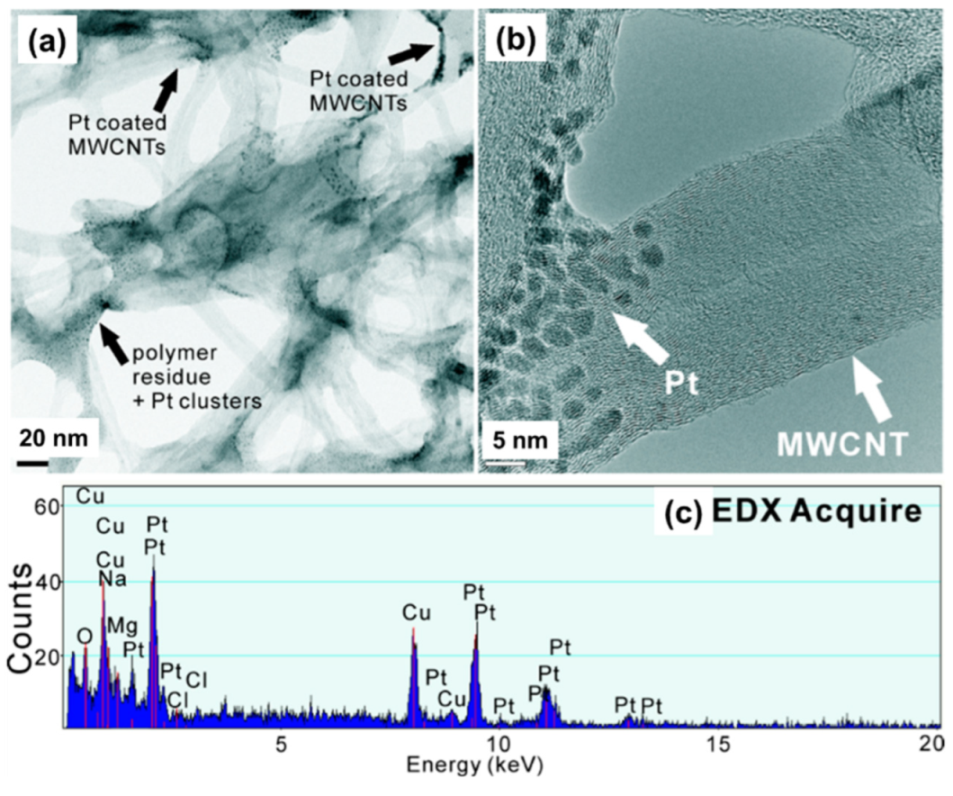
Transmission Electron Microscopy (TEM) images and the EDX analysis of Pt-coated MWCNT are shown in Figure 2. Figure 2a confirms a uniform Pt nanoparticle distribution (black dots) on the surface of the MWCNTs using our modified “layer-by-layer” coating approach. Polymer residue and Pt agglomerated clusters were still found on the surface of MWCNTs as pointed out by arrows. The higher magnification of the TEM image (Figure 2b) shows that the Pt have been coated as small clusters with diameters in range of 2.0 to 5.0 nm on the surface of the MWCNTs. EDX analysis confirmed Pt deposition on the surface of MWCNTs (Figure 2c).

2.3. Dispersion of Pt Coated MWCNTs

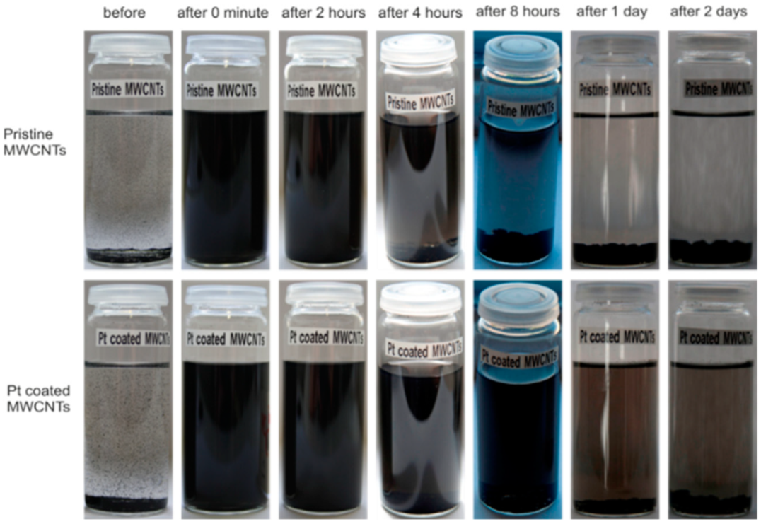
The dispersibility and dispersion stability of Pt-coated MWCNTs were compared to pristine MWCNTs. By using the same amount of MWCNTs in the same amount of ethanol after the same treatment (ultrasonification for 15 min), the difference between Pt coated MWCNTs and pristine MWCNTs can be observed in Figure 3. Straight after ultrasonification, both solutions showed an evenly black colour (after 0 min) and after two hours, the difference was still not too obvious. However, after 4 h, the pristine MWCNTs started re-agglomerating and black MWCNT agglomerations could be observed on the bottom of the bottle; while for Pt-coated MWCNTs, the solutions were still all black and no obvious agglomerations could be observed, which can be attributed to the improved dispersion stability by coating Pt on the CNTs. After 8 h, more agglomerates of pristine MWCNTs could be found on the bottom of the bottle while the solution of Pt-coated MWCNTs stayed clearly black. After 1 day and 2 days, the solution of the pristine MWCNTs showed a much lighter colour compared to Pt coated MWCNTs and big agglomerations could be found on the bottom, while the solution of Pt coated MWCNTs still presented a rather even black colour with fewer agglomerations on the bottom. The behaviour could be explained as the Pt coating maybe acting as spacers to break van der Waals force among the MWCNTs and preventing them from re-agglomerating; therefore, the Pt coated MWCNTs have an improved dispersion ability and stability.

2.4. Compression Tests of Composite

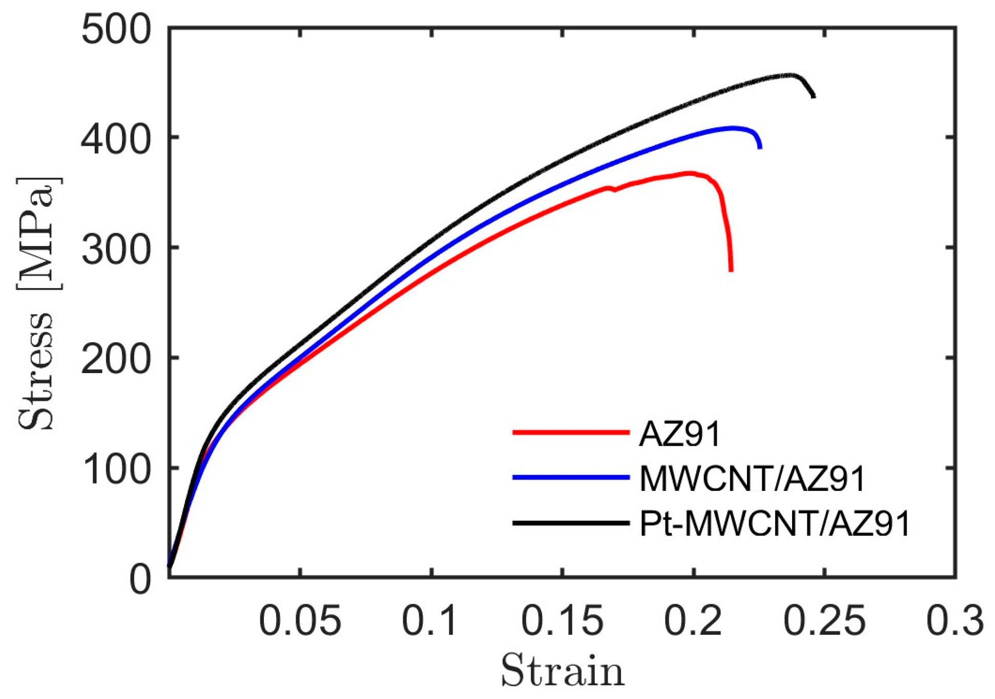
We performed a compression test to evaluate the effect of Pt coating on the mechanical properties of the composite. To improve the statistical significance of the results, 36 specimens were tested following the same procedure. We compared the ultimate compressive strength (UCS), yield strength (YS), and compression strain at failure (CSF) for pure AZ91, MWCNT/AZ91, and Pt-coated MWCNT/AZ91 composites systems. The typical compression stress–strain curves in Figure 4 illustrate that embedding MWCNTs and Pt-coated MWCNT can improve the mechanical properties of AZ91 composites.
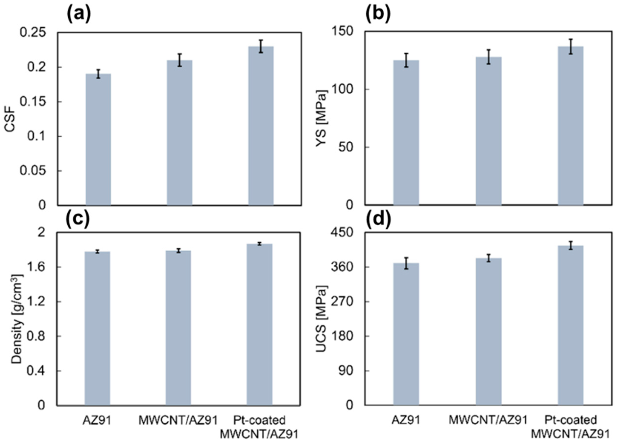
The yield strength of Pt-coated MWCNT/AZ91 has increased by about 10% compared to pure AZ91 and 7% compared to raw MWCNT/AZ91. The ultimate compressive strength of Pt-coated MWCNT/AZ91 has increased by 12% compared to pure AZ91 and by 9% compared to MWCNT/AZ91. Compression strain at failure of the Pt-coated MWCNT/AZ91 has the most improvement, as it increased by 21% compared to pure AZ91 and by 10% compared to raw MWCNT/AZ91. The density of the samples was also measured. By adding raw MWCNTs and Pt-coated MWCNTs, the densities of both composites have not been changed much compared to pure AZ91 alloy. A comparison between these values is depicted in Figure 5 and is detailed in Table 1.
The data were subjected to an analysis of variance (ANOVA) using R [55], and the results are summarised in Table 2. We found a statistically significant difference between the mechanical properties extracted from the compression testing for the three different kinds of samples with Pr values below the typically used 0.05 threshold.
Based on this finding, a Tukey Honest Significant Differences (HSD) post-hoc test [56] was used for a multiple pairwise comparison between the three sample types and the outcome is reported in Table 3. Comparing the results of the Pt coated MWCNT/AZ91 composites with the pure AZ91, we find very low p-values demonstrating the statistical significance of the observed improvements in properties for the coated MWCNTs. On the other hand, the comparison between pure AZ91 and the uncoated MWCNT/AZ91 composites give high p-values, underlining the ineffectiveness of using uncoated MWCNTs as reinforcements in the described processing route. Comparing the results of for the composites using uncoated and coated MWCNT, we see statistical significance with low p-values for the differences in UCS and CSF, while the yield strength gives a borderline result with a p-value around 0.09. This deviation is most likely related to the experimental difficulties in determining the yield strength from compression testing introducing more noise into the data. Overall, these results underline the effectiveness of the coating approach compared to both the pure alloy and the use of uncoated MWCNT as reinforcements.
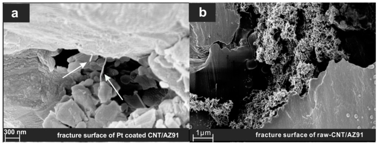
Figure 6 depicts the fracture morphology of Pt-coated and uncoated MWCNTs in Mg composites after compression testing characterised by scanning electron microscope (SEM). In the case of the uncoated MWCNT/AZ91 composite, we often observe micro-sized clusters of agglomerated MWCNT at the fracture surface, as shown in Figure 6b. The organic dispersion agent in uncoated MWCNT/Mg decomposes in the high temperature melting process. Eventually, in the absence of the organic dispersion agent and due to the MWCNT’s high surface energy, large surface area, and poor wettability with Mg, MWCNTs tend to adhere to each other and agglomerate. On the other hand, in the Pt-coated MWCNT/Mg composite, MWCNTs are observed getting pulled out individually at the fracture surface, as shown in Figure 6a. We attribute this observation to the fact that Pt nanoparticles deposited at the surface of MWCNT are stable and do not melt away during the high temperature melting process, and act as a spacer between the MWCNTs, which inhibits the agglomeration of MWCNTs in Mg melt and matrices. We observe no fractured MWCNTs at the fracture surface of both Pt-coated and uncoated MWCNT/Mg composite. This means that the failure mechanism of MWCNT/Mg in both case of Pt-coated and uncoated MWCNTs is the pull-out process. Attaching Pt nanoparticles on the surface of MWCNTs delays the pull-out process of MWCNTs from the fracture surface as the interface energy and interface shear stress between Pt and CNTs are higher than Mg and CNT [22,51,57], which results in a higher ultimate compression strength and compression strain at failure, as shown in Figure 4 and Figure 5. To shed light on the pull-out behaviour of CNTs in the Mg matrix, we perform pull-out simulations of Pt-coated and uncoated CNTs from Mg matrices using molecular dynamics simulation.

3. Atomistic Simulation Procedure and Results

We consider a single crystal Mg block with faces aligned in the [ 1 2 ¯ 10 ] , [ 1 ¯ 010 ] , and [ 0001 ] directions. Mg atoms are initially put on a perfect hcp crystal with lattice constant of 3.19 Å. The simulation box of the Mg lattice is periodic in all directions. The energy of the system was minimised through structural relaxation using a CG algorithm. An armchair (5,5) single-walled CNT (SWCNT) is then embedded into the centre of the Mg block; this is because, in our previous study, we demonstrated that for a constant diameter of CNT, increasing the number of CNT walls does not change the pull-out behaviour of MWCNTs [41]. To create the requisite space, we remove the Mg atoms that are located inside the CNT or within a distance of less than 3.5 Å from carbon atoms. The longitudinal axis of the CNT is parallel to the [ 1 2 ¯ 10 ] , which aligns with the x direction of the Cartesian coordination’s system. We carry out structural minimisation using a CG algorithm and a thermal equilibration procedure, where Mg atoms are annealed at 1200 K for 50 ps in NpT ensemble at zero pressure, and then quenched to 0.1 K at a rate of 1 K/ps. A final structural minimisation is then performed to remove any excess energy in the system. In the case of the Pt-coated CNT/Mg composite, before embedding the Pt-coated CNT in the Mg matrix, the Pt coating layers around the CNT is annealed at 2300 K for 20 ps in the NpT ensemble at zero pressure, and then quenched to 0.1 K at a rate of 10 K/ps. During this anneal-quench cycle, the CNT atoms are fixed.
The standard adaptive intermolecular reactive bond order (AIREBO) potential [57] was chosen for C-C interactions and the Embedded Atom Model (EAM)/alloy potentials of Zhou et al. [58] for metal-metal interactions. The Mg-C interface was described using a standard 12-6 LJ potential (ε = 0.0027 eV and σ = 3.75 Å) as in [59]. A Morse potential of the form E M = D M [ e 2 α ( r r 0 ) 2 e α ( r r 0 ) ] was used for describing Pt-C interactions, where r is the bond distance, r0 the equilibrium bond distance, DM is the well depth, and α controls the stiffness of the potential. The parameters for Pt-C morse potentials are DM = 0.0071 eV, r0 = 4.18 Å, and α= 1.05 Å−1 [49].
To set up a CNT pull-out test, the velocities of the Mg atoms at the boundary of the simulation box were fixed to zero, and a constant velocity of 0.1 Å/ps was imposed for 1000 ps on the CNT front layer (30 Carbon atoms). The remaining atoms were thermostatted to a temperature of 1 K using a Nosé-Hoover thermostat [60] with a characteristic relaxation time of 0.1 ps. To have sufficient space in the pull-out direction, the simulation box was extended to more than twice the CNT length. During pull-out, the potential energy, as well as the total reaction force acting on the CNT front layer, were recorded.
Figure 7 depicts the differences in pull-out force and energy between uncoated and Pt-coated (5,5) SWCNT. In both cases, the pull-out behaviour is of pure sliding out without energy dissipation at the interface. This is consistent with our experimental observations in Figure 6 when Pt-coated MWCNTs were found pulled-out of the fracture surface. The pull-out force oscillates around a value of 0.175 eV/Å for uncoated CNT and of 0.727 eV/Å for Pt-coated CNT. These values match the average slope of the potential’s energy increase, which corresponds to the product of CNT circumference and interface energy. The adhesion energy between Pt-C is higher than Mg-C; therefore, the pull-out force increases by a factor of five when CNT is coated by platinum. The corresponding interface shear stress (IFSS) between Mg and CNT is 10.9 MPa, and in the case of the Pt and CNT, it is 41.5 MPa. We should note that although the pull-out force and pull-out energy increases by Pt-coating, the interface characteristics between Pt and CNT is of physically adsorbed type in which no chemical bondings between metal and CNTs are formed [61,62,63]. The only commitment between metal and CNT in this model is the weak physical interactions, which will disappear under the shear stress of less than 50 MPa [49]. Therefore, CNTs, independent on their length, start to slide inside the matrix and get pulled out as soon as the matrix ruptures, and they have little significant load-transfer strengthening effects on the Mg matrix.

4. Conclusions

Multiwall carbon nanotubes have been coated by island-like clusters of Pt atoms via polyelectrolyte PDDA and PSS. By adding small amounts of Pt coated MWCNTs, the mechanical properties of Mg AZ91 composites have been improved over pure AZ91, especially compared to composites produced using un-coated MWCNTs. We attribute this enhancement to a better dispersion of Pt-coated MWCNTs in AZ91 Mg melt and conclude that Pt-decoration may inhibit MWCNTs re-agglomeration in metal melt. In composites with Pt-coated MWCNTs, individual MWCNTs can be observed on the fracture surface indicating that MWCNTs were dispersed individually. Simulations demonstrated that Pt coating led to enhanced interfacial bonding between MWCNTs and Mg metal matrix. Future work will be needed to investigate the microstructure of the composites by TEM, to optimise the metal coating process in order to have a good control of desired Pt deposition, and to investigate whether the process can be transferred to different metal matrix and coating materials.

Author Contributions

Formal analysis, Q.L.; Investigation, S.N. and Q.L.; Methodology, S.N. and Q.L.; Project administration, Q.L.; Software, S.N.; Supervision, E.S. and Q.L.; Visualization, G.Y.; Writing—original draft, S.N. and Q.L.; Writing—review & editing, S.N., E.S. and Q.L. All authors have read and agreed to the published version of the manuscript.

Funding

Part of this research is funded by the German Research Foundation (DFG) under grant LI 1847/2. SN acknowledges DFG funding under Za171/11-1.

Data Availability Statement

The data presented in this study are available on request from Samaneh Nasiri.

Acknowledgments

The authors gratefully acknowledge the support of the Cluster of Excellence ‘Engineering of Advanced Materials’ at the University of Erlangen-Nuremberg, which is funded by the DFG within the framework of its Excellence Initiative under grant EXC 315-1. We thank Jan Schwerdtfeger, Claudia Backes and Christoph Dotzer for fruitful discussions.

Conflicts of Interest

The authors declare no conflict of interest.

References

  1. Sammalkorpi, M.; Krasheninnikov, A.; Kuronen, A.; Nordlund, K.; Kaski, K. Mechanical properties of carbon nanotubes with vacancies and related defects. Phys. Rev. B 2004, 70, 245416. [Google Scholar] [CrossRef] [Green Version]
  2. Lee, C.; Wei, X.; Kysar, J.W.; Hone, J. Measurement of the elastic properties and intrinsic strength of monolayer graphene. Science 2008, 321, 385–388. [Google Scholar] [CrossRef] [PubMed]
  3. Nasiri, S.; Zaiser, M. Rupture of graphene sheets with randomly distributed defects. AIMS Mater. Sci. 2016, 3, 1340–1349. [Google Scholar] [CrossRef]
  4. Khare, R.; Mielke, S.L.; Paci, J.T.; Zhang, S.; Ballarini, R.; Schatz, G.C.; Belytschko, T. Coupled quantum mechanical/molecular mechanical modeling of the fracture of defective carbon nanotubes and graphene sheets. Phys. Rev. B 2007, 75, 075412. [Google Scholar] [CrossRef] [Green Version]
  5. Zhang, L.; Zhang, F.; Yang, X.; Long, G.; Wu, Y.; Zhang, T.; Leng, K.; Huang, Y.; Ma, Y.; Yu, A.; et al. Porous 3D graphene-based bulk materials with exceptional high surface area and excellent conductivity for supercapacitors. Sci. Rep. 2013, 3, 1408. [Google Scholar] [CrossRef] [PubMed] [Green Version]
  6. Stoller, M.D.; Park, S.; Zhu, Y.; An, J.; Ruoff, R.S. Graphene-based ultracapacitors. Nano Lett. 2008, 8, 3498–3502. [Google Scholar] [CrossRef]
  7. Zhang, S.; Wang, H.; Liu, J.; Bao, C. Measuring the specific surface area of monolayer graphene oxide in water. Mater. Lett. 2020, 261, 127098. [Google Scholar] [CrossRef]
  8. Deng, L.; Young, R.J.; Kinloch, I.A.; Sun, R.; Zhang, G.; Noé, L.; Monthioux, M. Coefficient of thermal expansion of carbon nanotubes measured by Raman spectroscopy. Appl. Phys. Lett. 2014, 104, 051907. [Google Scholar] [CrossRef] [Green Version]
  9. Pop, E.; Varshney, V.; Roy, A.K. Thermal properties of graphene: Fundamentals and applications. MRS Bull. 2012, 37, 1273–1281. [Google Scholar] [CrossRef] [Green Version]
  10. Balandin, A.A. Thermal properties of graphene and nanostructured carbon materials. Nat. Mater. 2011, 10, 569. [Google Scholar] [CrossRef] [Green Version]
  11. Esawi, A.M.K.; Borady, M.A.E. Carbon nanotube-reinforced aluminium strips. Compos. Sci. Technol. 2008, 68, 486–492. [Google Scholar] [CrossRef]
  12. Bakshi, S.R.; Agarwal, A. An analysis of the factors affecting strengthening in carbon nanotube reinforced aluminum composites. Carbon 2011, 49, 533–544. [Google Scholar] [CrossRef]
  13. Abazari, S.; Shamsipur, A.; Bakhsheshi-Rad, H.R.; Ismail, A.F.; Sharif, S.; Razzaghi, M.; Ramakrishna, S.; Berto, F. Carbon Nanotubes (CNTs)-Reinforced Magnesium-Based Matrix Composites: A Comprehensive Review. Materials 2020, 13, 4421. [Google Scholar] [CrossRef] [PubMed]
  14. Ding, C.; Gan, W.; Hu, X.; Wu, K.; Wang, X. Investigation into the influence of carbon nanotubes addition on residual stresses and mechanical properties in the CNTs@SiCp/Mg-6Zn hybrid composite using neutron diffraction method. Mater. Sci. Eng. A 2020, 797, 140105. [Google Scholar] [CrossRef]
  15. Nam, D.H.; Kim, Y.K.; Cha, S.I.; Hong, S.H. Effect of CNTs on precipitation hardening behavior of CNT/Al–Cu composites. Carbon 2012, 50, 4809–4814. [Google Scholar] [CrossRef]
  16. Chen, B.; Shen, J.; Ye, X.; Jia, L.; Li, S.; Umeda, J.; Takahashi, M.; Kondoh, K. Length effect of carbon nanotubes on the strengthening mechanisms in metal matrix composites. Acta Mater. 2017, 140, 317–325. [Google Scholar] [CrossRef]
  17. Li, B.Q.; Sui, M.L.; Li, B.; Ma, E.; Mao, S.X. Reversible twinning in pure aluminum. Phys. Rev. Lett. 2009, 102, 205504. [Google Scholar] [CrossRef] [Green Version]
  18. Chen, B.; Li, S.; Imai, H.; Jia, L.; Umeda, J.; Takahashi, M.; Kondoh, K. Load transfer strengthening in carbon nanotubes reinforced metal matrix composites via in-situ tensile tests. Compos. Sci. Technol. 2015, 113, 1–8. [Google Scholar] [CrossRef]
  19. Chen, B.; Kondoh, K.; Umeda, J.; Li, S.; Jia, L.; Li, J. Interfacial in-situ Al2O3 nanoparticles enhance load transfer in carbon nanotube (CNT)-reinforced aluminum matrix composites. J. Alloy. Compd. 2019, 789, 25–29. [Google Scholar] [CrossRef]
  20. Kim, Y.; Lee, J.; Yeom, M.S.; Shin, J.W.; Kim, H.; Cui, Y.; Kysar, J.W.; Hone, J.; Jung, Y.; Jeon, S.; et al. Strengthening effect of single-atomic-layer graphene in metal-graphene nanolayered composites. Nat. Commun. 2013, 4, 2114. [Google Scholar] [CrossRef]
  21. Nasiri, S.; Zaiser, M. Effects of elasticity and dislocation core structure on the interaction of dislocations with embedded CNTs in aluminium: An atomistic simulation study. Materialia 2022, 21, 101347. [Google Scholar] [CrossRef]
  22. Cheng, K.; He, D.; Peng, T.; Lv, H.; Pan, M.; Mu, S. Porous graphene supported Pt catalysts for proton exchange membrane fuel cells. Electrochim. Acta 2014, 132, 356–363. [Google Scholar] [CrossRef]
  23. Choi, H.-J.; Jung, S.-M.; Seo, J.-M.; Chang, D.W.; Dai, L.; Baek, J.-B. Graphene for energy conversion and storage in fuel cells and supercapacitors. Nano Energy 2012, 1, 534–551. [Google Scholar] [CrossRef]
  24. George, R.; Kashyap, K.T.; Rahul, R.; Yamdagni, S. Strengthening in carbon nanotube/aluminium (CNT/Al) composites. Scr. Mater. 2005, 53, 1159–1163. [Google Scholar] [CrossRef]
  25. Li, Q.; Viereckl, A.; Rottmair, C.A.; Singer, R.F. Improved processing of carbon nanotube/magnesium alloy composites. Compos. Sci. Technol. 2009, 69, 1193–1199. [Google Scholar] [CrossRef]
  26. Choi, B.K.; Yoon, G.H.; Lee, S. Molecular dynamics studies of CNT-reinforced aluminum composites under uniaxial tensile loading. Compos. Part B Eng. 2016, 91, 119–125. [Google Scholar] [CrossRef]
  27. Park, D.M.; Kim, J.H.; Lee, S.J.; Yoon, G.H. Analysis of geometrical characteristics of CNT-Al composite using molecular dynamics and the modified rule of mixture (MROM). J. Mech. Sci. Technol. 2018, 32, 5845–5853. [Google Scholar] [CrossRef]
  28. Xiang, J.; Xie, L.; Meguid, S.A.; Pang, S.; Yi, J.; Zhang, Y.; Liang, R. An atomic-level understanding of the strengthening mechanism of aluminum matrix composites reinforced by aligned carbon nanotubes. Comput. Mater. Sci. 2017, 128, 359–372. [Google Scholar] [CrossRef]
  29. Nasiri, S.; Wang, K.; Yang, M.; Guénolé, J.; Li, Q.; Zaiser, M. Atomistic aspects of load transfer and fracture in CNT-reinforced aluminium. Materialia 2022, 22, 101376. [Google Scholar] [CrossRef]
  30. Zhang, D.; Shen, P.; Shi, L.; Jiang, Q. Wetting of B4C, TiC and graphite substrates by molten Mg. Mater. Chem. Phys. 2011, 130, 665–671. [Google Scholar] [CrossRef]
  31. Goh, C.S.; Wei, J.; Lee, L.C.; Gupta, M. Development of novel carbon nanotube reinforced magnesium nanocomposites using the powder metallurgy technique. Nanotechnology 2005, 17, 7–12. [Google Scholar] [CrossRef]
  32. Goh, C.S.; Wei, J.; Lee, L.C.; Gupta, M. Simultaneous enhancement in strength and ductility by reinforcing magnesium with carbon nanotubes. Mater. Sci. Eng. A 2006, 423, 153–156. [Google Scholar] [CrossRef]
  33. Zhou, S.-M.; Zhang, X.-B.; Ding, Z.-P.; Min, C.-Y.; Xu, G.-L.; Zhu, W.-M. Fabrication and tribological properties of carbon nanotubes reinforced Al composites prepared by pressureless infiltration technique. Compos. Part A Appl. Sci. Manuf. 2007, 38, 301–306. [Google Scholar] [CrossRef]
  34. Deng, C.F.; Wang, D.Z.; Zhang, X.X.; Li, A.B. Processing and properties of carbon nanotubes reinforced aluminum composites. Mater. Sci. Eng. A 2007, 444, 138–145. [Google Scholar] [CrossRef]
  35. Li, Q.; Rottmair, C.A.; Singer, R.F. CNT reinforced light metal composites produced by melt stirring and by high pressure die casting. Compos. Sci. Technol. 2010, 70, 2242–2247. [Google Scholar] [CrossRef] [Green Version]
  36. Ip, S.W.; Sridhar, R.; Toguri, J.M.; Stephenson, T.F.; Warner, A.E.M. Wettability of nickel coated graphite by aluminum. Mater. Sci. Eng. A 1998, 244, 31–38. [Google Scholar] [CrossRef]
  37. Chu, H.Y.; Lin, J.F. Experimental analysis of the tribological behavior of electroless nickel-coated graphite particles in aluminum matrix composites under reciprocating motion. Wear 2000, 239, 126–142. [Google Scholar] [CrossRef]
  38. Guo, M.L.T.; Tsao, C.-Y.A. Tribological behavior of aluminum/SiC/nickel-coated graphite hybrid composites. Mater. Sci. Eng. A 2002, 333, 134–145. [Google Scholar]
  39. Song, H.-Y.; Zha, X.-W. Influence of nickel coating on the interfacial bonding characteristics of carbon nanotube–aluminum composites. Comput. Mater. Sci. 2010, 49, 899–903. [Google Scholar] [CrossRef]
  40. Duan, K.; Li, L.; Hu, Y.; Wang, X. Enhanced interfacial strength of carbon nanotube/copper nanocomposites via Ni-coating: Molecular-dynamics insights. Phys. E Low-Dimens. Syst. Nanostruct. 2017, 88, 259–264. [Google Scholar] [CrossRef]
  41. Nasiri, S.; Wang, K.; Yang, M.; Li, Q.; Zaiser, M. Nickel coated carbon nanotubes in aluminum matrix composites: A multiscale simulation study. Eur. Phys. J. B 2019, 92, 186. [Google Scholar] [CrossRef] [Green Version]
  42. Kong, F.Z.; Zhang, X.B.; Xiong, W.Q.; Liu, F.; Huang, W.Z.; Sun, Y.L.; Tu, J.P.; Chen, X.W. Continuous Ni-layer on multiwall carbon nanotubes by an electroless plating method. Surf. Coat. Technol. 2002, 155, 33–36. [Google Scholar] [CrossRef]
  43. Jafri, R.I.; Sujatha, N.; Rajalakshmi, N.; Ramaprabhu, S. Au–MnO2/MWNT and Au–ZnO/MWNT as oxygen reduction reaction electrocatalyst for polymer electrolyte membrane fuel cell. Int. J. Hydrogen Energy 2009, 34, 6371–6376. [Google Scholar] [CrossRef]
  44. Yang, M.; Yang, Y.; Liu, Y.; Shen, G.; Yu, R. Platinum nanoparticles-doped sol–gel/carbon nanotubes composite electrochemical sensors and biosensors. Biosens. Bioelectron. 2006, 21, 1125–1131. [Google Scholar] [CrossRef] [PubMed]
  45. Day, T.M.; Unwin, P.R.; Wilson, N.R.; Macpherson, J.V. Electrochemical templating of metal nanoparticles and nanowires on single-walled carbon nanotube networks. J. Am. Chem. Soc. 2005, 127, 10639–10647. [Google Scholar] [CrossRef] [PubMed]
  46. Qu, L.; Dai, L. Substrate-enhanced electroless deposition of metal nanoparticles on carbon nanotubes. J. Am. Chem. Soc. 2005, 127, 10806–10807. [Google Scholar] [CrossRef] [PubMed]
  47. Du, N.; Zhang, H.; Wu, P.; Yu, J.; Yang, D. A general approach for uniform coating of a metal layer on MWCNTs via layer-by-layer assembly. J. Phys. Chem. C 2009, 113, 17387–17391. [Google Scholar] [CrossRef]
  48. Si, Y.; Samulski, E.T. Exfoliated graphene separated by platinum nanoparticles. Chem. Mater. 2008, 20, 6792–6797. [Google Scholar] [CrossRef]
  49. Nasiri, S.; Greff, C.; Wang, K.; Yang, M.; Li, Q.; Moretti, P.; Zaiser, M. Multilayer Structures of Graphene and Pt Nanoparticles: A Multiscale Computational Study. Adv. Eng. Mater. 2020, 22, 2000207. [Google Scholar] [CrossRef]
  50. Khomyakov, P.A.; Giovannetti, G.; Rusu, P.C.; Brocks, G.V.; Van den Brink, J.; Kelly, P.J. First-principles study of the interaction and charge transfer between graphene and metals. Phys. Rev. B 2009, 79, 195425. [Google Scholar] [CrossRef] [Green Version]
  51. Schneider, W.B.; Benedikt, U.; Auer, A.A. Interaction of platinum nanoparticles with graphitic carbon structures: A computational study. ChemPhysChem 2013, 14, 2984–2989. [Google Scholar] [CrossRef]
  52. Ramos-Sanchez, G.; Balbuena, P. Interactions of platinum clusters with a graphite substrate. Phys. Chem. Chem. Phys. 2013, 15, 11950–11959. [Google Scholar] [CrossRef]
  53. Gan, Y.; Sun, L.; Banhart, F. One-and Two-Dimensional Diffusion of Metal Atoms in Graphene. Small 2008, 4, 587–591. [Google Scholar] [CrossRef]
  54. Hippmann, S.; Li, Q.; Addinal, R.; Volk, W. Carbon nanotubes–reinforced copper matrix composites produced by melt stirring. Proc. Inst. Mech. Eng. Part N J. Nanoeng. Nanosyst. 2013, 227, 63–66. [Google Scholar] [CrossRef] [Green Version]
  55. Everitt, B. Statistical Models in S; Chambers, J.M., Hastie, T.J., Eds.; Book reviews; Statistical Methods in Medical Research; Wadsworth and Brooks/Cole: Los Angeles, CA, USA, 1992; Volume 1, pp. 220–221. ISBN 0-534-16765-9. [Google Scholar]
  56. Yandell, B.S. Practical Data Analysis for Designed Experiments; Taylor & Francis: Abingdon, UK, 1997. [Google Scholar]
  57. Stuart, S.J.; Tutein, A.B.; Harrison, J.A. A reactive potential for hydrocarbons with intermolecular interactions. J. Chem. Phys. 2000, 112, 6472–6486. [Google Scholar] [CrossRef] [Green Version]
  58. Zhou, X.W.; Johnson, R.A.; Wadley, H.N.G. Misfit-energy-increasing dislocations in vapor-deposited CoFe/NiFe multilayers. Phys. Rev. B 2004, 69, 144113. [Google Scholar] [CrossRef] [Green Version]
  59. Zhou, X.; Song, S.; Li, L.; Zhang, R. Molecular dynamics simulation for mechanical properties of magnesium matrix composites reinforced with nickel-coated single-walled carbon nanotubes. J. Compos. Mater. 2016, 50, 191–200. [Google Scholar] [CrossRef]
  60. Evans, D.J.; Holian, B.L. The Nose–Hoover thermostat. J. Chem. Phys. 1985, 83, 4069–4074. [Google Scholar] [CrossRef]
  61. Vanin, M.; Mortensen, J.J.; Kelkkanen, A.K.; Garcia-Lastra, J.M.; Thygesen, K.S.; Jacobsen, K.W. Graphene on metals: A van der Waals density functional study. Phys. Rev. B 2010, 81, 081408. [Google Scholar] [CrossRef] [Green Version]
  62. Gong, C.; Lee, G.; Shan, B.; Vogel, E.M.; Wallace, R.M.; Cho, K. First-principles study of metal–graphene interfaces. J. Appl. Phys. 2010, 108, 123711. [Google Scholar] [CrossRef]
  63. Fampiou, I.; Ramasubramaniam, A. Binding of Pt nanoclusters to point defects in graphene: Adsorption, morphology, and electronic structure. J. Phys. Chem. C 2012, 116, 6543–6555. [Google Scholar] [CrossRef]
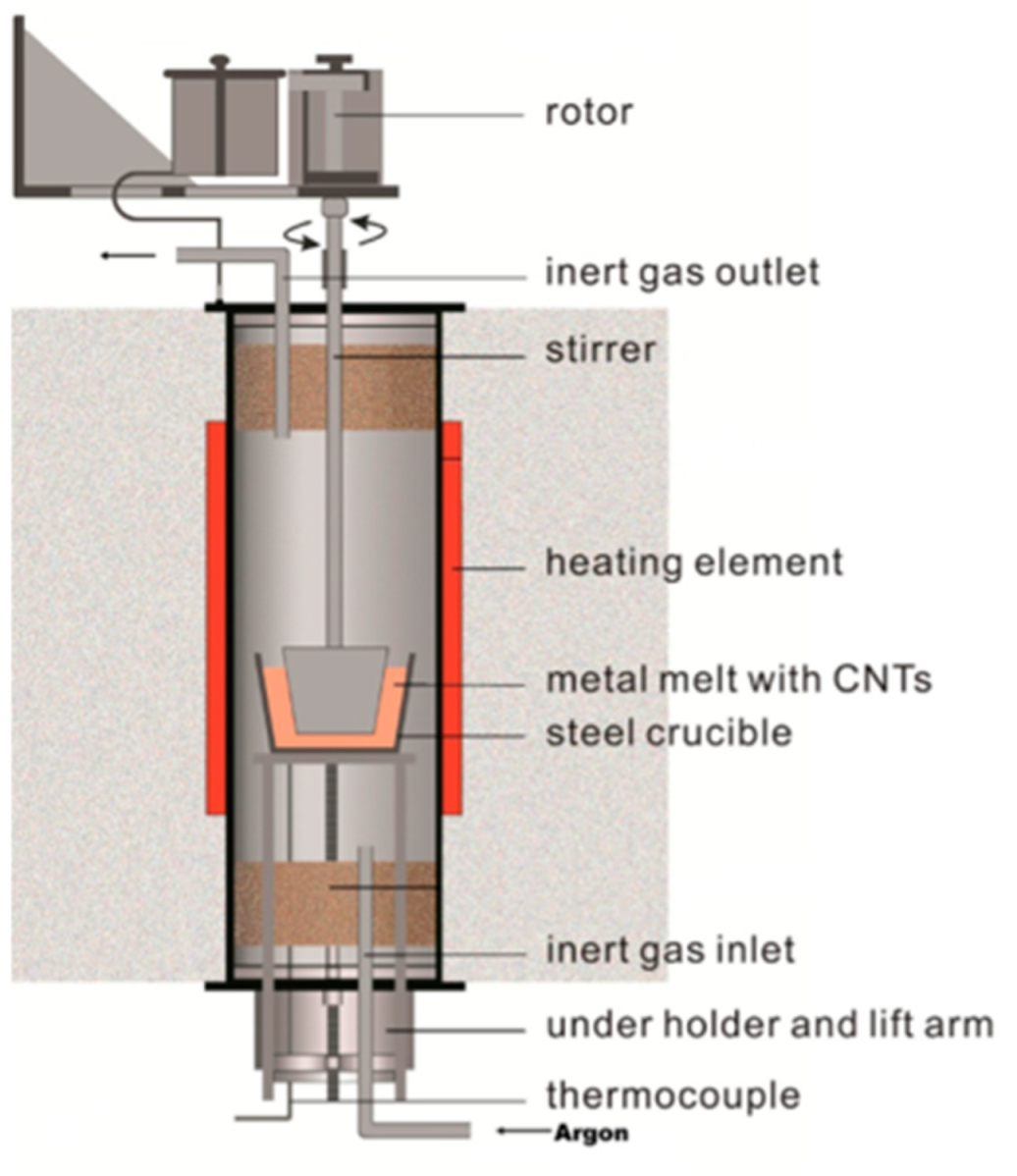
Figure 1. Schematic drawing of the melt stirring furnace used in this study.
Metals 12 00834 g001
Figure 2. TEM image of overview of Pt coated MWCNTs (containing 30 wt% of Pt), containing Pt-coated MWCNTs and polymer residue with Pt clusters; (a) Overview TEM image of Pt coated MWCNTs; (b) TEM image of Pt coating on the surface of individual MWCNTs; (c) EDX analysis of selected area on the surface.
Metals 12 00834 g002
Figure 3. Dispersion ability and stability of Pt coated CNTs and pristine CNTs. Same weight (1.14 mg) of Pt coated CNT (coating ratio has been considered) and pristine CNTs in same amount of ethanol (20 mL). Sonicated for 15 min.
Metals 12 00834 g003
Figure 4. Typical stress-strain curves of pure AZ91, 0.05 wt% uncoated MWCNT/AZ91 composite, and 0.05 wt% Pt-MWCNT/AZ91 composite.
Metals 12 00834 g004
Figure 5. Comparison of (a) compression strain at failure (CSF), (b) yield strength (YS), (c) density, and (d) ultimate compressive strength (UCS) between pure AZ91, 0.05 wt% MWCNT/AZ91 composite, and 0.05 wt% Pt-coated MWCNT/AZ91 composite.
Metals 12 00834 g005
Figure 6. Fracture surface of (a) Pt coated CNT/AZ91 composite and (b) raw CNT/AZ91 composite after compression test. Arrow points at the individual CNT pulled out of the fracture surface after failure.
Metals 12 00834 g006
Figure 7. MD simulation of CNT pull-out from Mg matrix; (a) pristine CNT in Mg matrix, (b) Pt-coated in Mg matrix; inset pictures show the cross section of the configuration during the pull-out simulation. Blue, red, and yellow atoms at the insets represent Mg, C, and Pt atoms, respectively.
Metals 12 00834 g007
Table 1. Experimental values of yield strength (YS), ultimate compressive strength (UCS), compression strain at failure (CSF), and density of pure AZ91, 0.05 wt% MWCNT/AZ91, and 0.05 wt% Pt-coated MWCNT/AZ91.
Sample2% YS [MPa]UCS [Mpa]CSF [%]Density [g/cm3]
AZ91125 ± 5.6370 ± 14.419 ± 0.61.78 ± 0.01
MWCNT/AZ91128 ± 5.8383 ± 9.321 ± 0.91.79 ± 0.02
Pt-MWCNT/AZ91137 ± 7.0416 ± 10.023 ± 0.91.87 ± 0.01
Table 2. Results of one-way ANOVA of yield strength (YS), ultimate compressive strength (UCS), and compression strain at failure (CSF) for different samples of pure AZ91, 0.05 wt% MWCNT/AZ91, and 0.05 wt% Pt-coated MWCNT/AZ91. * Significant code.
2% YS
FactorDegree of FreedomSum of SquaresMean SquareF ValuePr Value
Different samples (Pure AZ91,
MWCNT/AZ91,
Pt-MWCNT/AZ91)
2949474.55.3446.08 × 10−3
Residuals34301988.8
USC
Different samples215,767788334.736.08 × 10−9
Residuals347717227
CSF
Different samples247.2823.6429.164.21 × 10−8
Residuals3427.560.811
Table 3. Tukey HSD post-hoc test for yield strength (YS), ultimate compressive strength (UCS), and compression strain at failure (CSF) pairwise comparing the sample groups: pure AZ91, 0.05 wt% MWCNT/AZ91, and 0.05 wt% Pt-coated MWCNT/AZ91.
2% YS
SampleDifference of MeansLwrUprAdjusted p-Value
AZ91 vs. MWCNT/AZ913.056250−8.48899614.601500.7943670
AZ91 vs. Pt-MWCNT/AZ9111.5477981.95428821.141310.0153950
Pt-MWCNT/AZ91 vs. MWCNT/AZ918.491548−1.10196218.085060.0912189
UCS
AZ91 vs. MWCNT/AZ9113.1500−5.3085031.608500.2032903
AZ91 vs. Pt-MWCNT/AZ9147.3184531.9803862.656520
Pt-MWCNT/AZ91 vs. MWCNT/AZ9134.1684518.8303849.506520.0000128
CSF
AZ91 vs. MWCNT/AZ910.637500−0.4655871.7405870.3440493
AZ91 vs. Pt-MWCNT/AZ912.5609521.6443433.4775610.0000002
Pt-MWCNT/AZ91 vs. MWCNT/AZ911.9234521.0068432.8400610.0000328
Publisher’s Note: MDPI stays neutral with regard to jurisdictional claims in published maps and institutional affiliations.