Article

Investigation of the Hearth Erosion of WISCO No. 1 Blast Furnace Based on the Numerical Analysis of Iron Flow and Heat Transfer in the Hearth

1
Key Laboratory for Ferrous Metallurgy and Resources Utilization of Ministry of Education, Wuhan University of Science and Technology, Wuhan 430081, China
2
Hubei Provincial Key Laboratory for New Processes of Ironmaking and Steelmaking, Wuhan University of Science and Technology, Wuhan 430081, China
3
Baosteel Central Research Institute (R&D Center of Wuhan Iron & Steel Co., Ltd.), Wuhan 430080, China
*
Authors to whom correspondence should be addressed.
Metals 2022, 12(5), 843; https://doi.org/10.3390/met12050843
Submission received: 10 April 2022 / Revised: 11 May 2022 / Accepted: 13 May 2022 / Published: 15 May 2022
(This article belongs to the Special Issue Mathematical Modelling of the Ironmaking Blast Furnace)

Abstract

:
The campaign life of a blast furnace is largely limited by the erosion state of its hearth section. Therefore, the study of hearth erosion is important for blast furnace ironmaking. In this study, the hearth erosion of the WISCO No. 1 blast furnace was investigated in combination with the numerical analysis of the iron flow and heat transfer in the hearth. The distributions of the wall shear stress and the temperature in the hearth were simulated and the hearth sections with high erosion risk were discussed. The hearth lining with higher shear stress is generally located near the taphole region and the 1423 K isotherm is totally located inside the hearth lining structure, with a deeper position in the central part of the hearth bottom. Based on the measurement data from the hearth damage investigation, the erosion state of the hearth bottom and the lower part of the hearth sidewall is more serious. The erosion line at the hearth bottom showed a typical “pot-bottom” shaped contour and for the hearth corner section, the average erosion depth was about 1/3 of the total wall thickness. The empirical expressions between the hearth erosion depth and the wall shear stress and the temperature were established. Moreover, the effects of key iron tapping factors on the wall shear stress and the effect of the hearth’s refractory structure on the heat transfer in the hearth are respectively discussed, aiming to provide more suggestions for hearth protection.

1. Introduction

The blast furnace (BF) still remains as the predominant ironmaking equipment, although various novel alternative non-BF technologies have emerged in recent decades [1]. On the other hand, considering the high costs for the BF construction and the subsequent maintenance, optimizing the productivity and economy of the BF smelting process has always been an important research issue in the ironmaking industry. Prolonging the campaign life of a BF can reduce not only the regular maintenance cost but also the economic loss due to the insufficient hot metal supply during BF downtime. Among the factors that affect the BF’s campaign life, the erosion of hearth refractories is relatively less controllable but is very important to the safety production of the BF. In other words, the hearth erosion problems largely determine the lower limit of BF campaign life and thus further affect the total financial cost and income of the steel enterprise [2].
The shear stress induced from the liquid iron flow near the hearth lining is one of the main hearth erosion mechanisms [3,4], so it is necessary to gain insight into the shear-stress distribution on the hearth lining to guide hearth maintenance. The iron flow pattern in the hearth is very complex since it is affected by the hearth geometry and the operating conditions. Moreover, due to the hostile hearth environment, it is hard to directly observe the iron flow or measure the key indices of iron flow in the hearth. Therefore, to fill this information gap, a series of numerical studies [5,6,7,8,9] about the hearth iron flow have been conducted. For example, Komiyama et al. [5] developed an improved 3-D numerical model using CFD (computational fluid dynamics) to analyze the iron flow state in the hearth of BlueScope’s Port Kembla No. 5 blast furnace under varying operating conditions. Cheng et al. [6] numerically studied the iron flow characteristics in the hearth during the tapping process by solving the Reynolds average Navier–Stokes equation. Wang et al. [7] studied the influence of the deadman status (sitting or floating) on the iron flow pattern in the BF hearth using the CFD method. Shao and Saxén [8] investigated the iron flow pattern and the erosion profile of the BF hearth. It was concluded that these two factors were largely dependent on the dynamic deadman state during the iron tapping cycle.
In addition to the wall shear stress caused by iron flow, the other major mechanisms of the hearth erosion include the thermo stress, the hot metal penetration, and the dissolution of carbon bricks. Therefore, understanding the heat transfer in the BF hearth still matters for the hearth’s protection. In most numerical studies [10,11,12,13,14], the heat transfer process in the hearth is simulated coupling with iron flow because the iron momentum field and the temperature field actually interact. Lai et al. [10] and Guo et al. [11] simulated the heat transfer in the BF hearth by taking the conjugate heat transfer and the natural convection into account. Chang et al. [12] developed a 3-D numerical model that considered the mass transfer of carbon in thermal convective flow from the BF hearth during the steady iron tapping process. Zhou et al. [13] studied the iron flow and the conjugate heat transfer through the hearth refractories using a 3-D CFD model, and the temperature distribution and the hearth erosion patterns were analyzed under different operating conditions. Jiao et al. [14] established a mathematical model to simulate the iron flow and the temperature field in the hearth of a commercial BF and the results showed that the convective heat transfer coefficient increased with the intensity of the molten iron circulation.
Although various numerical analyses of the iron flow and the heat transfer in the BF hearth have been conducted, the guidance of modeling work for the accurate prediction of hearth erosion still needs further discussion. In other words, how to effectively estimate the hearth erosion state by a series of simulation data is still a hot issue. Based on this consideration, some relevant attempts have been made in this work by taking a commercial BF as the research object. The No. 1 blast furnace at WISCO (Wuhan Iron and Steel Company, Wuhan, China) has safely run for more than 18 years (from May 2001 to October 2019) in its 4th campaign with a total iron production of 13,000 tHM/m3. Now this blast furnace has been permanently shut down as planned and will be transformed into a BF exhibit after a hearth damage investigation. Through this investigation, it is a good opportunity to gain insight into the relationship between the hearth erosion state and the numerical data related to the iron flow and temperature fields in the hearth. Hence, the application of numerical modeling to the hearth erosion study can be more meaningful and a clearer guidance for the hearth protection can be also achieved.
In this study, the iron flow behavior and the heat transfer phenomenon in the hearth of the WISCO No. 1 blast furnace were systematically simulated using a 3-D CFD model. The wall shear-stress distribution and the temperature distribution were analyzed in detail and their influence on the hearth erosion depth were investigated. Based on the above work, to provide more operation suggestions for hearth protection, the effects of key iron tapping factors, including the taphole’s depth, size, and inclination, on the wall shear stress were studied. In addition, the influence of the hearth’s refractory structure on the hearth temperature distribution was also discussed.

2. Physical System

2.1. Judgment of the Deadman State in the Hearth

The importance of the deadman state for the iron flow pattern in the hearth has been recognized by many scholars [15,16,17]. For the numerical study of the WISCO No. 1 BF, the deadman state in the hearth should be determined beforehand. In general, the deadman state (e.g., floating or sitting) can be estimated by the force analysis. According to Zhu et al. [18,19], the minimum depth of the static iron layer required for floating the deadman, hmin, is calculated by the following equation:
h min = ρ m g V m + ρ c g V H ( 1 ε d ) F b f ( ρ i ρ c ) ( 1 ε d ) g A h
where ρm is the average density of material column (kg/m3), ρc is the true density of coke (kg/m3), ρi is the density of molten iron (kg/m3), g is the acceleration of gravity (9.81 m/s2), Vm is the volume of material column (m3), VH is the volume of the section between the taphole and tuyere zones (m3), εd is the void fraction of deadman, and Ah is the cross-sectional area of the hearth (m2). Fb refers to the gas buoyant force (N), which is defined as
F b = ( 1000 Δ P 1.1 × 1.293 × v f 2 2 ) × A h
where ΔP is the pressure loss (kPa) and vf is the blast speed (m/s). f is the wall friction force (N) calculated by
f = 2 ρ m V e ( v d / 1000 ) 0.5 × d m 0.25 × g 0.75 / A h 0.25
where Ve is the effective volume of BF (m3), vd is the descending speed of charging material (mm/s), and dm is the average diameter of charging material (m). The main geometric design and the operating parameters of the WISCO No. 1 BF are shown in Table 1 and Table 2, respectively.
By substituting the data shown in Table 1 and Table 2 into Equation (1), the value of hmin was calculated as 2.84 m, which is larger than the designed depth of the static iron layer of the WISCO No. 1 BF (hd = 2.0 m). Therefore, the deadman in the hearth should be in the sitting state at the early and middle stages of the BF’s campaign life. At the late stage, due to the erosion of the hearth bottom, the actual depth of the static iron layer may be larger than hmin. However, since the iron tapping interval is shorter than the iron tapping period, the buoyant force provided by the molten iron stored in the hearth for the deadman is not stable. Therefore, it can be regarded that at the late stage, the deadman would be in a periodical “floating and sitting” state. For simplicity, in this simulation study, the deadman state was assumed as “fully sitting”.

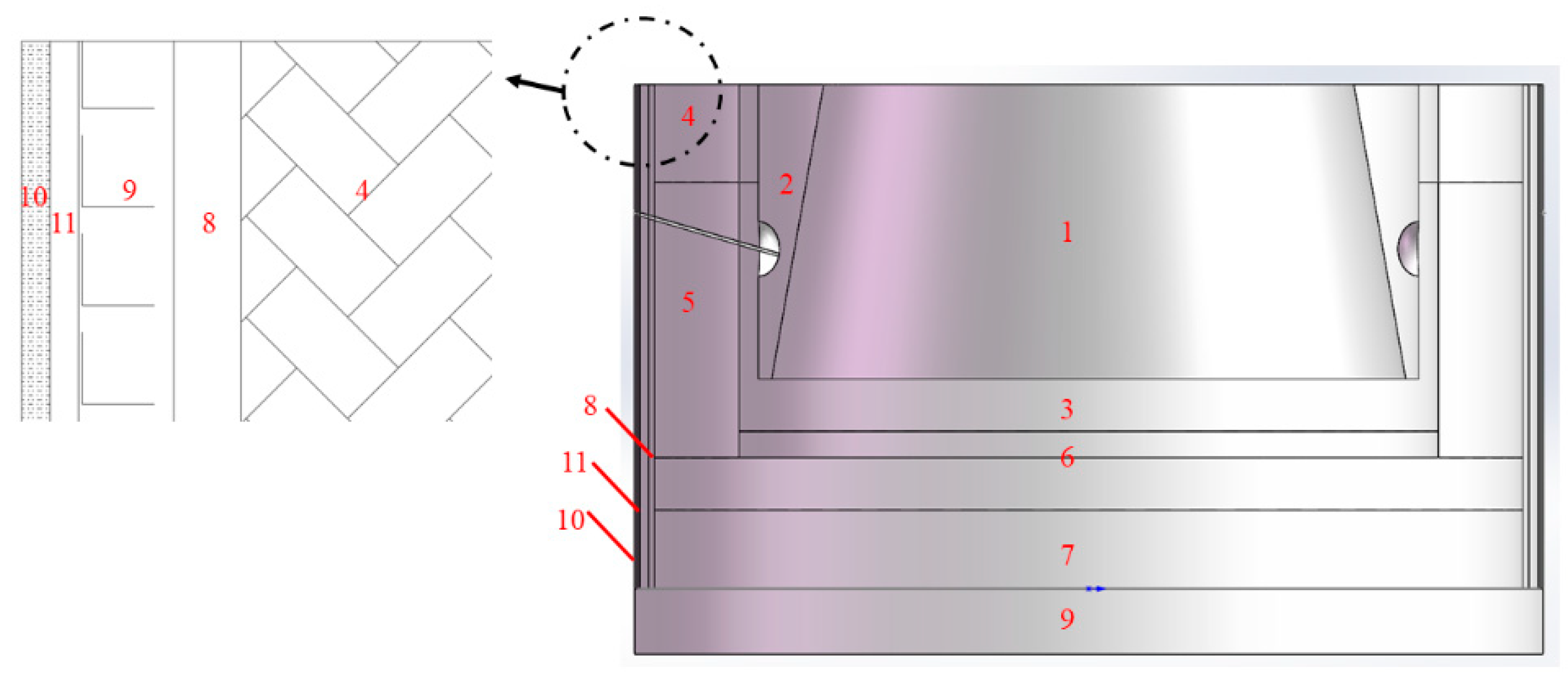
2.2. Physical Model Setting

A geometric model of the hearth of the WISCO No. 1 BF was established based on the design drawing, as shown in Figure 1. Since the deadman state was considered as fully sitting in the hearth, the coke-free zone (CFZ) only exits between the deadman and the hearth sidewall. The inclination and the average diameter of the deadman were estimated based on the hearth punching data. The average void fraction of the deadman was determined by the average measured volume fraction of the iron (or slag) remaining in the deadman samples. The other hearth geometric and operating parameters are shown in Table 3. The main physical properties of hot metal, coke, and the refractory materials are shown in Table 4 and Table 5, respectively.

3. Governing Equations and Numerical Method

3.1. Mathematical Model Description

The basic numerical assumptions in this study are as follows: (1) the geometry of the deadman was assumed as a truncated cone with an inclination of 80° as shown in Table 3; (2) the internal void structure of the deadman was isotropic so the void fraction of the deadman was assumed to be uniform; (3) the relevant chemical reactions were not considered in the simulation; and (4) the iron tapping process was in a continuous steady state. The governing equations of this simulation work are listed as below.
(1)
Continuity equation:
( ε ρ u ) = 0
where ε is the cell’s void fraction, ρ is the density of hot metal (kg/m3), and u is the velocity vector (m/s).
(2)
Momentum conservation equation:
( ε ρ u u ) = ε ( p + 2 3 ρ k ) + [ ε ( μ + μ t ) ( u + u T ) ] + ε ρ g β ( T T ref ) + ε S dm
where p, k, μ, μt, β, T, and Tref refer to pressure, turbulent kinetic energy, viscosity, turbulent eddy viscosity, thermal expansion coefficient, temperature, and Boussinesq reference temperature (1773 K), respectively. Sdm represents the momentum sink caused by the presence of the porous deadman:
S dm = 150 μ ( 1 ε ) 2 ε 3 d p 2 u 1.75 ρ 1 ε ε 3 d p | u | u
where dp is the average diameter of the coke particles in the deadman.
(3)
Shear-stress transport (SST) k-ω model [20]:
( ε ρ u k ) = [ ε ( μ + σ k μ t ) k ] + ε ( G k Y k )
( ε ρ u ω ) = [ ε ( μ + σ ω μ t ) ω ] + ε ( G ω Y ω ) + ε ( 1 F 1 ) D ω
where:
D ω = 2 ρ σ ω 2 k ω ω
λ = F 1 λ 1 + ( 1 F 1 ) λ 2 ,   λ = σ ,   G ,   Y
F 1 = tanh ( χ 4 ) ,   χ = min { max ( k 0.09 ω y , 500 μ ρ ω y 2 ) , 4 ρ k 1.168 D ω + y 2 }
D ω + = max ( D ω , 10 10 )
μ t = ρ k max ( ω ϕ , Γ F 2 0.31 )
ϕ = 0.144 + ρ k μ ω 6 + ρ k μ ω
F 2 = tanh { max ( k 0.045 y ω , 500 μ ρ y ω 2 ) 2 }
where ω is the flow energy dissipation rate; σk, σω are empirical constants; Gk, Gω are the generation terms; Yk, Yω are the dissipation terms; y is the distance to the next computational cell; Γ is the magnitude of the strain rate; and the subscripts of 1 and 2 refer to the original k-ω equations and standard k-ε equations, respectively.
(4)
Heat conservation equation:
ε ρ ( u T ) = [ ( λ C p + μ t 0.9 ) T ]
For the porous deadman:
λ dm = ε λ iron + ( 1 ε ) λ coke
where Cp is heat capacity; λdm, λiron, and λcoke are the heat conductivity of the deadman, hot metal, and coke particles, respectively.

3.2. Boundary Conditions

  • The upper surface of the hearth was set as the iron flow inlet with a uniform velocity calculated based on the average daily iron productivity (5000 tHM/d) of the WISCO No. 1 BF, and the iron temperature was assumed as constant (1805 K) at the inlet surface;
  • The taphole exit was set as the pressure outlet boundary (kept at 1.0 atm) and a mass flow boundary condition was implemented to ensure mass balance;
  • A no-slip condition existed on the inner surface of the refractory walls and the standard log-law wall function was applied for the iron velocity;
  • A coupled thermal boundary layer was modeled for the walls between the hot metal and the refractory walls;
  • The temperatures at the cold faces of the hearth were assumed as constant and the temperature at the upper surface of the refractory walls was set as adiabatic [21].

3.3. Numerical Method

The governing equations, subject to the given boundary conditions, were solved in a three-dimensional finite element model. In this model, the hearth section of the WISCO No. 1 BF (including deadman, coke-free zone, and refractory materials) was represented by a numerical body-fitted grid structure in a Cartesian coordinate system. The total number of the grid cells was about 3,850,000. To guarantee the simulation accuracy, for the regions where a high gradient of iron flow velocity may exist, e.g., the vicinity of taphole, the grid was properly arranged with a higher resolution. SIMPLEC (Semi-Implicit Method for Pressure Linked Equations Consistent) algorithm was applied in the pressure–velocity coupling in the segregated solver. Compared to the SIMPLE algorithm, the SIMPLEC algorithm can adjust the velocity correction at each mesh point to make the corrected pressure less aggressive and hence help accelerate the convergence via increasing the under-relaxation factor (generally set to 1.0). The upwind scheme was chosen to discrete the convective terms in each governing equation. The calculation was considered to be converged when all the normalized residuals of the pressure, velocity, and temperature fields reduced to 1.0 × 10⁻⁴.

4. Results and Discussion

4.1. Numerical Analysis of Iron Flow and Heat Transfer

Figure 2 shows the 3-D hearth geometric structure with a Cartesian coordinate to help understand the orientation of the numerical hearth model. The x direction is parallel with the taphole line which links the two mud ladles on the opposite sides of the hearth. The y direction is perpendicular to the x direction and the z direction which refers to the vertical height direction of the hearth.
Figure 3 shows the iron flow fields in the xz cross section through the taphole line and in the xy cross section with 1.5 m height from the hearth bottom. It can be seen that due to the lack of momentum sink in the coke-free zone (CFZ) (marked by black lines), most of the hot metal entering from the inlet originally tends to flow to the CFZ and then flows through the circumferential CFZ section to the vicinity of the taphole. The hot metal in the CFZ near the taphole has an obvious velocity gradient and the maximum flow velocity near the outlet can be higher than 5.0 × 10⁻³ m/s, which may cause high-risk shear stress on the corresponding areas of the hearth lining. On the opposite side of the taphole, there is another “dormant taphole” surrounded by a mud ladle for alternative iron tapping. In the current study, this dormant taphole did not participate in the iron tapping process. For the hot metal in the CFZ near this dormant taphole, its flow behavior is affected by the obstruction of this mud ladle, so its average flow velocity is smaller than that in the vicinity of the active taphole. Figure 3b shows that the iron flow field is generally symmetrically distributed along the taphole line on the xy cross section of the hearth. A circumferential iron flow towards the taphole zone is clearly shown with an obvious velocity acceleration in the CFZ. The simulation results shown in Figure 3 indicate that under the operating conditions of the hearth of the WISCO No. 1 BF, most of the hot metal generally first flows to the adjacent CFZ and then circumferentially flows through the CFZ to the taphole zone before finally leaving the hearth. For the hot metal close to the taphole zone, it would flow directly toward the taphole with an obvious velocity gradient.
The wall shear stress is normally induced from the velocity gradient of the iron flow near the hearth wall and its value is generally computed by the following equation:
τ wall = ( μ + μ t ) U p y p
where Up is the velocity in the wall adjacent cell and yp is its centroid distance. The shear-stress distributions on the hearth lining are important indicators of the potential high-risk areas subject to the physical wear erosion. Given the shear stress on the hearth lining calculated by Equation (18), the relatively vulnerable areas with higher shear stress can be easily identified. This information is the important data reference that guides the hearth protection of other BFs operating under similar conditions and extends the BF’s campaign life in the long run.
Figure 4 shows the simulated shear-stress distributions on the inner-sidewall and the bottom of the hearth. It can be seen that the overall shear-stress distribution on the inner-sidewall is approximately symmetrical about the taphole. The red zone representing for the maximum shear stress appears on the mud ladle. Since the mud ladle is the consumable material, its erosion situation was not considered in this study. Except for the mud ladle, the higher shear stress on the inner-sidewall distributes on both sides and the bottom of the taphole, showing a “C” shape with an obvious stress gradient along the circumferential direction. In contrast, the shear stress far away from the taphole region is obviously smaller. The high shear-stress area on the inner-sidewall generally corresponds to the area where the hot metal circulation is intensive, as shown in Figure 3, and vice versa. This further proves that the iron circulation flow has a direct influence on the magnitude of the wall shear stress. On the other hand, since the deadman of WISCO’s No. 1 BF was considered to be fully sitting in this study, the average iron flow velocity near the hearth bottom was quite low. As a result, the shear stress on the hearth bottom, as shown in Figure 4b, is obviously smaller than that on the inner-sidewall by a magnitude. The highest shear stress on the hearth bottom appears in the region close to the hearth corner under the taphole, which is similar to the iron velocity distribution in the xy cross section as shown in Figure 3b.
Since the hearth’s inner-sidewall is generally subject to the larger shear stress from the iron circulation flow compared with the hearth bottom, a more specific shear-stress analysis should be focused on this section. For example, in order to analyze the shear-stress distributions on the inner-sidewall at different heights, three semi-circumferential curves were selected on the inner-sidewall at the heights of 0.5 m, 1.5 m, and 2.5 m from the hearth bottom, named as Curve 1, 2, and 3, respectively. These three heights generally correspond to the lower position of the sidewall and the lower and higher boundaries of the near-taphole region, respectively. The wall shear-stress distributions along these three curves are shown in Figure 5. The results indicate that, from the active taphole to the dormant taphole (with the azimuthal angle range of 0~180°), the shear stress on the inner-sidewall generally shows a decreasing trend. For Curve 1 (at the height of 0.5 m), the shear stress first increases within the azimuthal angle range of 0~17° and then continues decreasing along the circumferential direction. The stress peak occurs at the azimuthal angle of 17° with the value of 7.10 × 10⁻⁴ Pa. For Curve 2 (at the height of 1.5 m), the shear stress first changes sharply within the azimuthal angle range of 0~14° due to the complex iron flow near the taphole and then gradually decreases. The stress peak occurs at the azimuthal angle of 14° with the value of 1.58 × 10⁻³ Pa. For Curve 3 (at the height of 2.5 m), the shear stress shows a monotonous decreasing trend along the circumferential direction. The peak stress is generally located at the azimuthal angle of 0° with the value of 1.05 × 10⁻³ Pa. Based on the above analysis, it can be found that, first, for the inner-sidewall region at a lower height, the peak stress occurs at a larger azimuthal angle and vice versa; second, the sequence of the peak shear stress of the sampling curves is Curve 2 > Curve 3 > Curve 1, which indicates that the sidewall area close to, especially below, the taphole zone, shows the largest shear stress, then followed by the area above the taphole, and the lowest wall shear stress appears in the lower part close to the hearth bottom.
The temperature distribution in the xz cross section of the hearth section is shown in Figure 6a. As the hot metal enters from the upper surface of the hearth, its average velocity gradually decreases under the overall effect of the porous deadman, so the heat transfer for the hot metal in the hearth is mainly controlled by heat conduction and thermal diffusion [22]. Moreover, through the conjugate heat transfer between the hot metal and the hearth’s refractory materials, there are obvious temperature gradients near the hearth’s refractory lining area, indicating the high potential erosion risk caused by thermo stress. In addition, since the heat transfer efficiency between the hot metal and the hearth lining below the taphole is increased due to the higher flow velocity, an obvious temperature gradient also exists in the corresponding hot metal region. Figure 6b shows the position of the 1423 K isotherm in the hearth section. The black straight lines indicate the surfaces of the hearth lining. As the temperature of the hot metal is lower than the melting point, the hot metal would transit from the liquid phase to the solid phase that adheres to the hearth lining surface and helps prevent further hearth erosion [23,24]. Therefore, the melting temperature of the hot metal, defined as 1423 K in this study, is also taken as the critical thermal erosion temperature of the hearth. The red curve in Figure 6b is depicted based on the positions of the cells at the temperature of 1423 K, so it can be called the thermal erosion line. The results show that under the operation conditions of WISCO’s No. 1 BF, the 1423 K isotherm is wholly located inside the hearth lining, indicating the potential thermal erosion of the hearth lining. The thermal erosion depth in the side hearth lining gradually increases as the hearth height increases. This is probably attributed to the different carbonate refractory materials in the height direction of the side hearth. The erosion depth in the bottom hearth lining gradually increases from the hearth corner section to the central section.

4.2. Discussion of the Hearth Erosion of WISCO No. 1 BF

Based on the analysis in Section 4.1, it can be seen that the iron flow pattern in the hearth has a direct influence on the wall shear stress and temperature distributions in the hearth section; hence, it largely determines the hearth erosion state [25,26,27]. Due to the existence of the deadman in the hearth, the iron circulation flow basically aggravates the mechanical erosion of the hearth lining through intensive physical scouring, which finally causes the periodical delamination and peeling of the refractory bricks. The erosion degree is closely related to the iron velocity gradient near the wall, as indicated by Equation (18). Based on the wall shear-stress distributions shown in Figure 4 and Figure 5, the hearth lining with higher shear stress is generally located between the near-taphole regions within the azimuthal angle range of 0~20° and within the height range of 1.0~2.0 m from the hearth bottom. Therefore, this lining section should be paid enough attention to avoid severe mechanical erosion.
The thermal erosion of the hearth mainly originates from the corrosion of the hot metal on the hearth’s refractory bricks. The liquid hot metal can continually penetrate into the hearth’s lining bricks (e.g., high-alumina bricks) which have a high thermal resistance. With the decrease in the lining brick thickness, a higher temperature gradient would occur inside the lining bricks and, as a result, the lining bricks would gradually shatter under the effect of high thermal stress. Afterwards, the carbon bricks are exposed to the hot metal. The saturated carbon mass fraction of the hot metal is proportional to the temperature. Therefore, the hot metal with higher temperature would speed up the dissolution of the carbon bricks and, hence, aggravate the thermal erosion. Based on the simulation results in Figure 6, the 1423 K isotherm is located inside the hearth’s lining bricks, indicating that the iron solidification layer cannot form on the lining surface to prevent further corrosion. Moreover, since the 1423 K isotherm shows a deeper position in the central part of the hearth bottom, this section may suffer from more severe corrosion of hot metal. It can be expected that a “pot-bottom” shaped erosion profile may occur at the hearth bottom in the long run.
The hearth damage investigation can help understand the actual hearth erosion state of the blast furnace during its campaign life and the collected hearth information is important for future hearth protection [28,29]. Figure 7 shows the measured erosion profile on the hearth cross section near No. 97 water pipe (at the azimuthal angle of 20° from the taphole) of the WISCO No. 1 BF. It can be seen that the erosion at the hearth bottom and the lower part of the hearth sidewall is more serious. For the hearth bottom part, the measured erosion line shows a typical “pot-bottom” shaped contour, and the deepest erosion position has almost reached the bottom of the first layer of micropore carbon bricks. For the hearth sidewall, the average erosion depth is about 1/4 of the total wall thickness, and the deepest erosion depth, which is located at the hearth corner section, is about 1/3 of the total wall thickness. In general, the erosion state of the hearth sidewall, including the corner section, is acceptable for the WISCO No. 1 BF with a campaign life of 18 years. The remaining wall thickness is still in a relatively good state. As for the carbon bricks at the hearth bottom, although half of the total refractory materials has been eroded, its remaining thickness is still relatively safe for iron production according to the hearth design. Therefore, the overall hearth erosion state of the WISCO No. 1 BF can be regarded as satisfactory.
Since the hearth erosion mechanisms are very complex and the erosion process is unsteady, the actual hearth erosion depth can be difficult to predict purely through the numerical study. Based on the measurement data of the hearth damage investigation, a relationship between the hearth erosion depth and the wall shear stress and temperature for WISCO’s No. 1 BF is established. This relationship is an empirical expression obtained by the multiple regression analysis of the measured hearth erosion depth and the simulated wall shear stress and temperature of the cells at the corresponding positions. This empirical expression is mainly to provide a reference for estimating the potential severe hearth erosion areas, based on the relevant simulated results, of other BFs operating under similar conditions to those of the WISCO No. 1 BF.
In this study, the measured hearth erosion depth distributions at four cross sections near No. 17, No. 49, No. 97, and No. 116 water pipes of the WISCO No. 1 BF were used for the regression analysis. In the regression analysis, the hearth bottom and the sidewall were analyzed separately since the contributions of wall shear stress and temperature for the hearth erosion are different in these two sections. For each regression result, the values of the determination coefficient (R2) and the significance level (p-value) were checked to ensure that the regression model was valid. Then the standard regression coefficient (i.e., the contribution weight factor) of each parameter in the model was recorded. Based on the regression results of the four cross sections, the relationship between the erosion depth, h, and the temperature, T, and the wall shear stress, τ, was summarized as follows:
h bot = ( 0.908 ~ 0.937 ) T + ( 0.058 ~ 0.082 ) τ
h side = ( 0.262 ~ 0.295 ) T + ( 0.727 ~ 0.746 ) τ
where the subscripts of “bot” and “side” refer to the hearth bottom and the sidewall sections, respectively. For the hearth bottom section, the average standard regression coefficient of temperature is greatly larger than that of wall shear stress by a magnitude. This indicates that the erosion depth at the hearth bottom is much more dependent on the temperature compared to the wall shear stress. For the WISCO No. 1 BF, the sitting-state deadman limits the iron flow near the hearth bottom so the hearth bottom erosion is mainly caused by thermo stress, hot metal penetration, and the dissolution of carbon bricks. In comparison, due to the iron circulation flow in the CFZ, the erosion depth on the sidewall is largely influenced by the wall shear stress, although the contribution weight of temperature is also not negligible. In general, the empirical expressions shown in Equations (19) and (20) can provide a preliminary understanding of the relationship between the hearth erosion depth and the key numerical parameters of the iron flow and heat transfer in the hearth, which helps the comprehensive hearth erosion analysis of the WISCO No. 1 BF.

4.3. Influence of Iron Tapping Factors on the Iron Flow Field

In this section, the influence of taphole depth, taphole size, and taphole inclination on the iron flow field in the hearth of WISCO’s No. 1 BF was studied to optimize the shear-stress distribution on the sidewall. The ranges of taphole depth, taphole size, and taphole inclination were chosen as 2.7 m~3.1 m, 50 mm~60 mm, and 11.5°~13.5°, respectively. The simulation project was based on the orthogonal design in which several representative cases were taken into account to reduce the total number of simulation cases. This method is efficient and reasonable, so it has been applied in various research fields [30,31,32].
In this study, three levels of each factor were considered so an L9 (33) orthogonal table was designed as shown in Table 6. Considering the article length, in this section, only the No. 7 case (i.e., taphole depth of 3.1 m, taphole size of 50 mm, and taphole inclination of 12.5°) is presented as a data analysis example. Compared with the original operation conditions of the WISCO No. 1 BF, the taphole in the No. 7 case is largely deepened and the taphole inclination is also slightly increased. Figure 8 shows the iron flow fields of the No. 7 case in the xz cross section through the taphole and in the xy cross section with 1.5 m height from the hearth bottom, respectively. In the No. 7 case, the iron outlet is located inside the deadman. Under this iron tapping condition, a large proportion of the hot metal tends to flow to the taphole zone directly through the deadman instead of flowing to the CFZ first. This change significantly reduces the average velocity of the iron circulation flow in the CFZ, and hence decreases the shear stress on the hearth sidewall.
The shear-stress distributions on the semi-circumferential curves (at the height of 1.5 m) of the sidewall between the original the No. 1 BF case and the No. 7 case are shown in Figure 9. In the No. 7 case, the average wall shear stress is largely reduced compared with that of the original No. 1 BF case, with the peak shear stress dropping from 1.58 × 10⁻³ Pa to 3.36 × 10⁻⁴ Pa. Figure 10 shows the shear-stress distribution on the inner-sidewall of the hearth in the No. 7 case. It can be seen that the shear-stress distribution is still symmetrical about the taphole. The highest shear-stress area (except for the mud ladle) is located on both sides of the taphole, with an azimuthal angle of about 25°. The shear stress below the taphole becomes obviously smaller compared with the value shown in the original No. 1 BF case (see Figure 4a), which can be explained by the weakening of the iron circulation flow in the CFZ under the taphole. The above comparison results indicate that a deeper taphole with a larger inclination is helpful in reducing the wall shear stress on the hearth lining, but the contribution weight of each factor should be determined based on the range analysis of all the simulation results.
Table 6 also summarizes the peak wall shear stress on the hearth sidewall in each case. By taking taphole depth, taphole size, and taphole inclination as Factors A, B, and C, respectively, the corresponding range analysis was conducted and the results are shown in Figure 11. It can be seen that as the taphole depth increases from 2.7 m to 3.1 m (from A1 to A3), the peak shear stress decreases sharply. As the taphole size increases from 50 mm to 60 mm (from B1 to B3), the peak shear stress does not change obviously. As the taphole inclination increases from 11.5° to 13.5° (from C1 to C3), the peak shear stress presents a moderate upward trend. The above results indicate that the taphole depth (Factor A) has the greatest influence on the wall shear stress, followed by the taphole inclination (Factor C), while the effect of taphole size (Factor B) on the wall shear stress is not significant. Therefore, the optimum tapping operation combination can be regarded as the taphole depth of 3.1 m and the taphole inclination of 11.5°. Taphole sizes within the range of 50 mm~60 mm should be all acceptable. A brief conclusion can be drawn that, under the normal iron tapping conditions, properly increasing the taphole depth and decreasing the taphole inclination can reduce the shear stress on the hearth sidewall, while the influence of taphole size is not obvious.

4.4. Influence of the Hearth’s Refractory Structure on the Temperature Field

An unreasonable hearth refractory structure may result in poor heat transfer in the hearth and an increased erosion rate of the hearth lining, which would, at worst, cause serious burn-through accidents. Therefore, compared to the quality of the refractory materials, a well-designed hearth refractory structure is equally important for hearth protection. At present, the refractory carbon bricks used for hearth construction are mainly categorized into large-size and small-size carbon bricks, the features of which are summarized in Table 7. The schematic diagrams of the corresponding hearth structures are shown in Figure 12.
Considering the features of the hearth structures using the large-size and small-size carbon bricks, a composite hearth structure using both types of carbon bricks, as shown in Figure 13, was proposed to further improve the heat transfer in the hearth section. This structure takes the advantages of the large-size carbon brick structure with fewer brickwork joints and the small-size carbon brick structure with higher overall heat conductivity. The ramming filler between the large-size and small-size carbon bricks is closer to the hot surface of the hearth lining, which promotes its solidification efficiency. In this hearth structure, the heat conductivity of each part generally increases from the inside to the outside of the hearth, which is beneficial to the heat transfer in the hearth structure and the formation of a solid iron shell on the hot surface of the hearth lining.
In order to study the heat transfer effect of this composite carbon brick structure, a simulation work using this structure was conducted. In this case, the heat conductivity of the small-size carbon bricks was set 50% higher than that of the corresponding large-size carbon bricks. The resultant temperature field was compared with that of the WISCO No. 1 BF case which uses the large-size carbon brick structure. To clearly show the difference of the 1423 K isotherm position between these two cases, the coordinates of the hearth cells at the temperature of 1423 K were extracted and plotted. Figure 14 shows the 1423 K isotherm lines on the xz cross section of hearth sidewall through the taphole. The comparison shows that when the composite carbon brick structure is used, the 1423 K isotherm shifts towards the hot surface of the sidewall by several centimeters while the isotherm shape does not change significantly. This indicates that the composite carbon brick structure improves the heat transfer in the hearth structure and pushes the 1423 K isotherm toward the hot surface of the hearth lining. However, the change in the 1423 K isotherm position between these two cases is not significant, especially at the lower part of the sidewall. Therefore, the current composite carbon brick structure still needs optimization to further improve the heat transfer effect in future work. On the other hand, it also indicated that the traditional large-size carbon brick structure still has relatively good heat transfer effect, which laid the foundation for the safe iron production of the WISCO No. 1 BF for 18 years.

4.5. Further Discussions on the Erosion of the BF’s Hearth

In addition to the simulation results of WISCO’s No. 1 BF hearth and the relevant erosion analysis shown above, there are also two points that can be further discussed. First, the iron circulation flow, which is the main cause of the mechanical erosion of the No. 1 BF hearth, is largely dependent on the deadman state. The sitting deadman excludes the CFZ near the hearth bottom and hence contributes to the development of the iron circulation flow near the hearth sidewall. In addition, the width of the CFZ near the hearth sidewall, which is largely dependent on the raw material and fuel conditions and smelting intensity, also affects the intensity of iron flow circulation. This indicates that when designing a BF hearth, the general iron flow pattern in the hearth can be predicted in advance based on the BF’s key operation parameters such as the raw material and fuel conditions and the hot blast blowing conditions and the hearth’s key structural parameters such as the hearth diameter and the depth of the taphole. Therefore, some precautionary work during hearth construction, e.g., increasing the hearth lining thickness or improving the wear resistance of the lining bricks in the potential high shear-stress sections, can be done to reduce the long-term mechanical erosion risk of the hearth. This method is very effective and is low cost.
Second, compared with the medium-size WISCO No. 1 BF (2200 m3), a BF with a larger effective volume may be under a more severe hearth erosion situation. To validate this assumption, an additional numerical study of the WISCO No. 6 BF, which has a similar hearth structure and deadman state to the No. 1 BF, was conducted. The WISCO No. 6 BF has a larger effective volume (3200 m3) and a higher daily productivity (about 7500 tHM/d). The simulation results show that the average wall shear stress on the hearth sidewall of the No. 6 BF is 12.5% larger than that of the No. 1 BF. In addition, the 1423 K isotherm in the sidewall and bottom sections of the No. 6 BF is also deeper than that of the No. 1 BF by an average of 0.03 m and 0.05 m, respectively. The detailed comparison results will be published in a future paper. This comparison result indicates that for a larger BF, the hearth erosion risk due to both mechanical and thermal erosion mechanisms may be more severe than for a smaller one. Considering that BF enlargement has been a prevailing trend in the worldwide ironmaking industry, the hearth protection work of large-size BF also becomes more challenging and more important for safe production.

5. Conclusions

The hearth erosion state of WISCO’s No. 1 BF was investigated in combination with a numerical study of the iron flow pattern and heat transfer in the hearth. The distributions of wall shear stress and temperature in the hearth were analyzed emphatically and their influence on the hearth erosion depth were discussed. Moreover, the effects of key iron tapping factors on the wall shear stress and the effect of the hearth’s refractory structure on the temperature distribution were respectively studied, aiming to provide more suggestions for hearth protection. The main conclusions are shown as below.
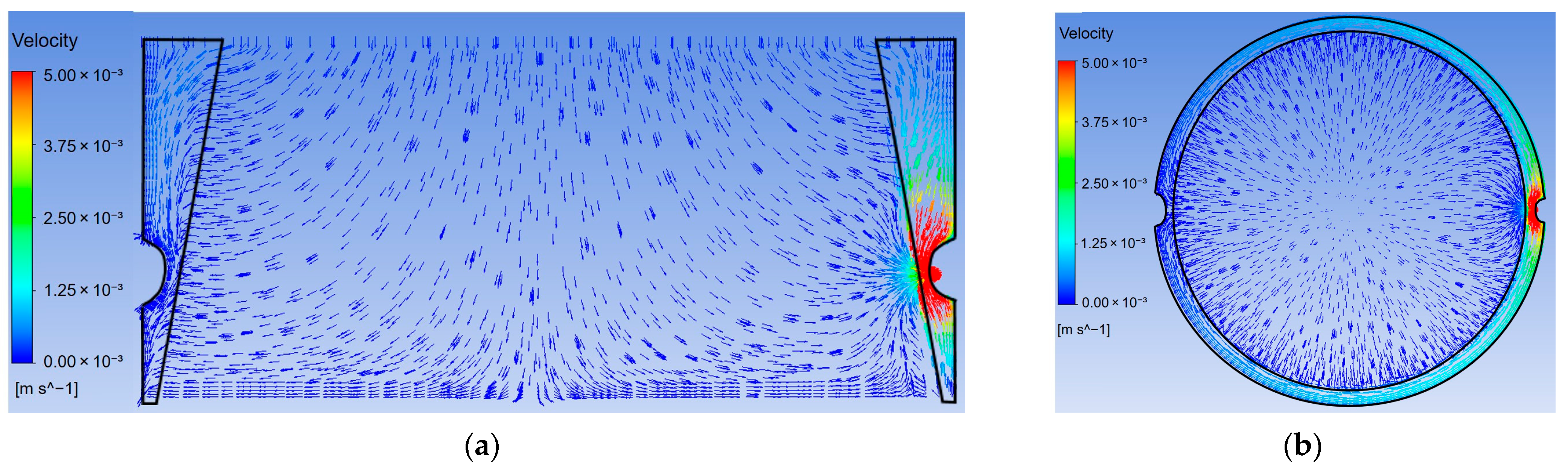
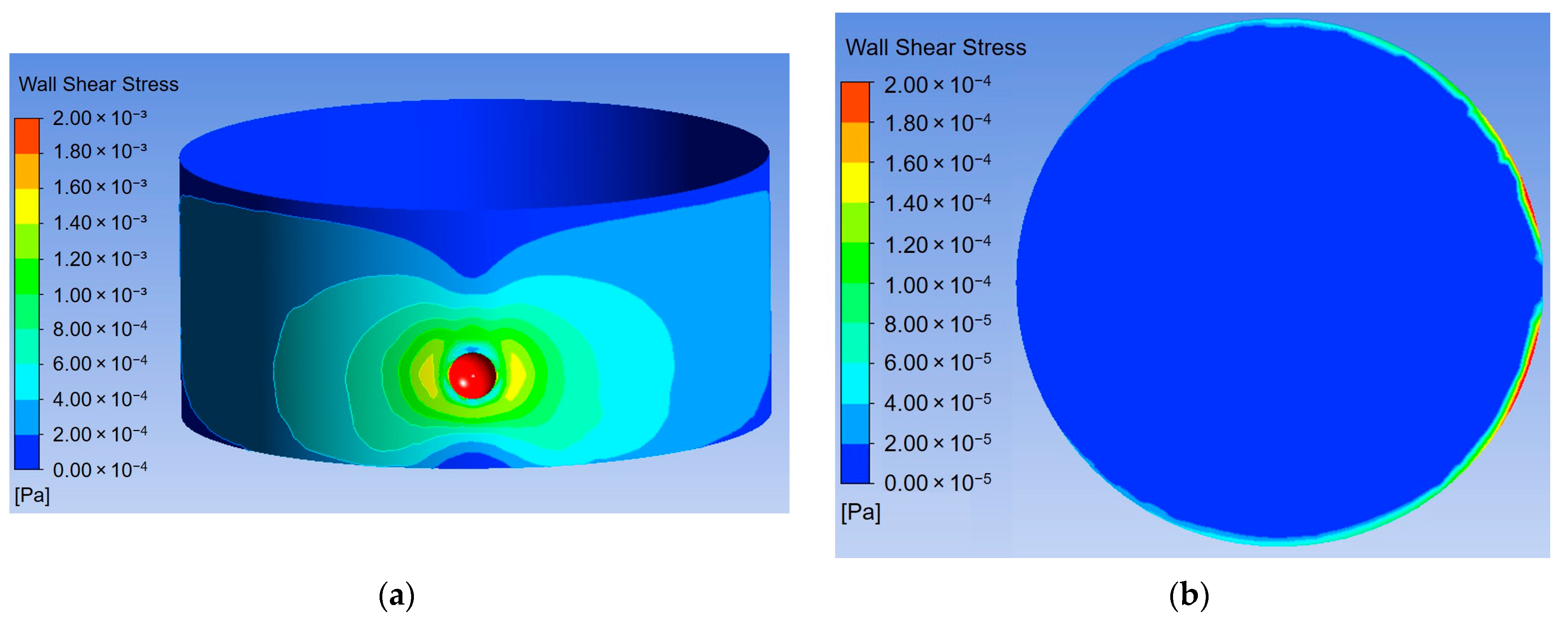
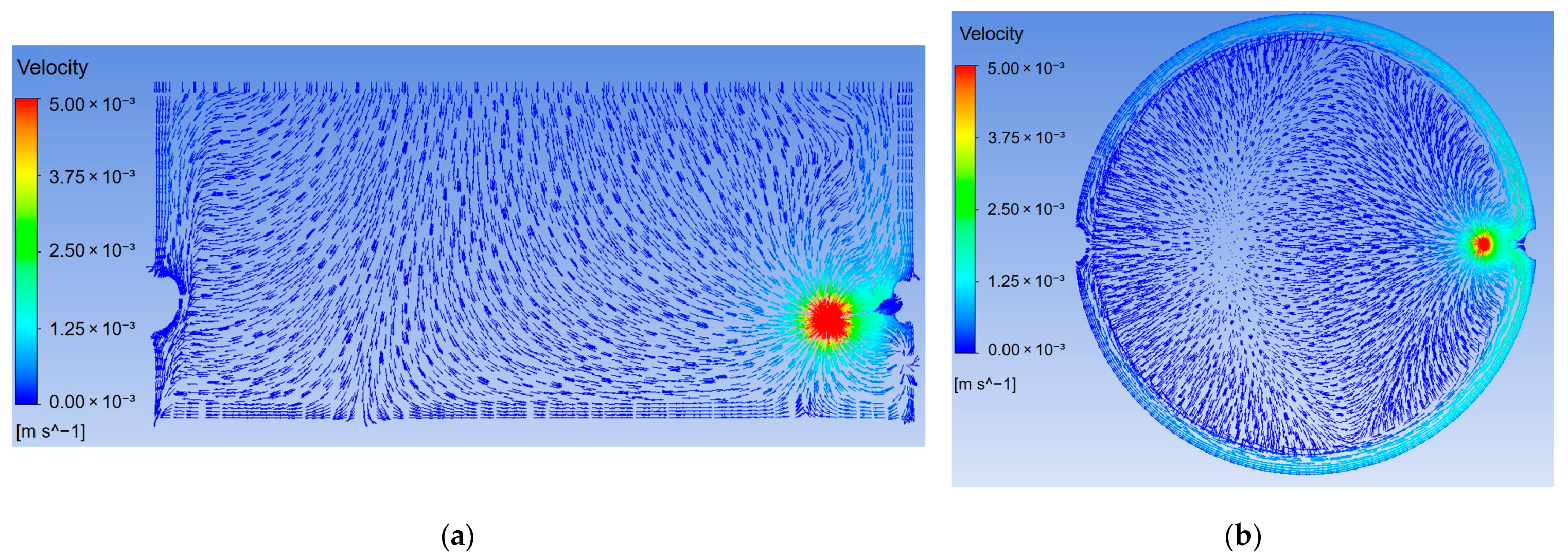
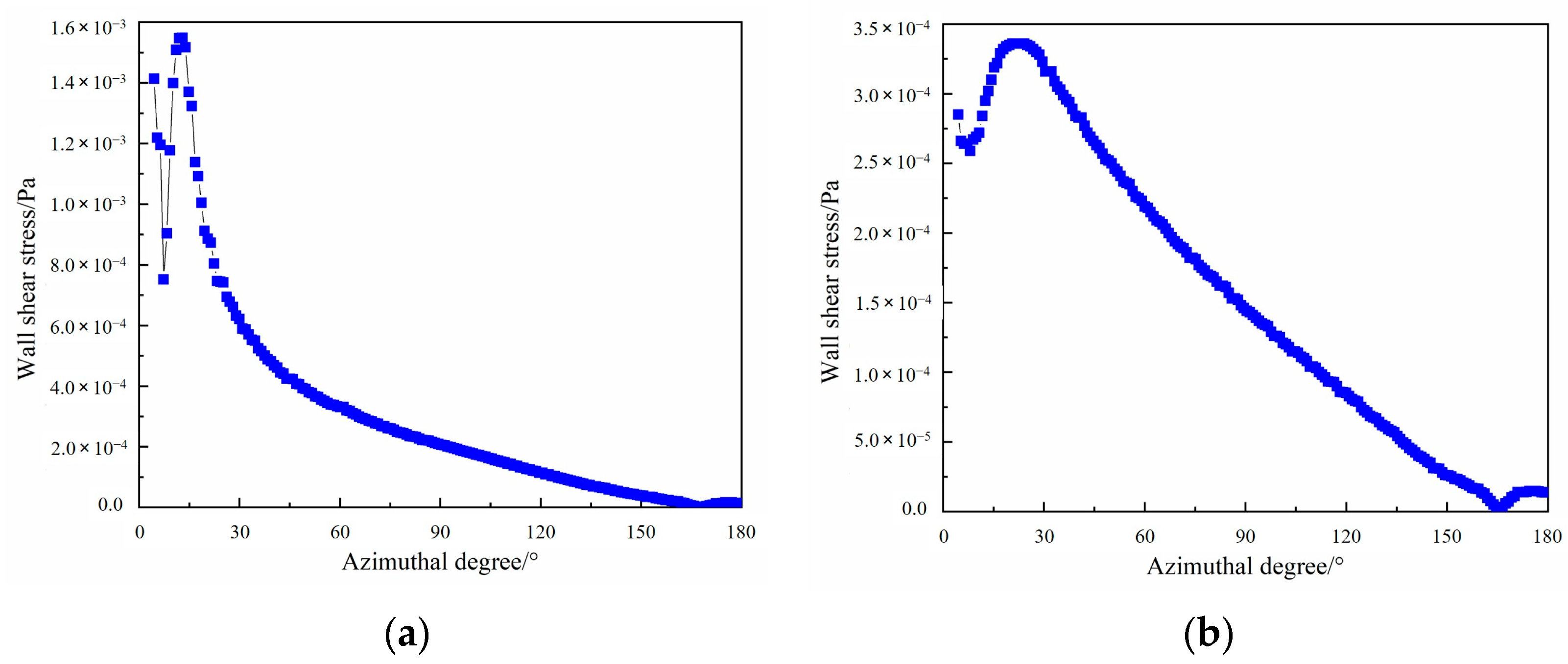
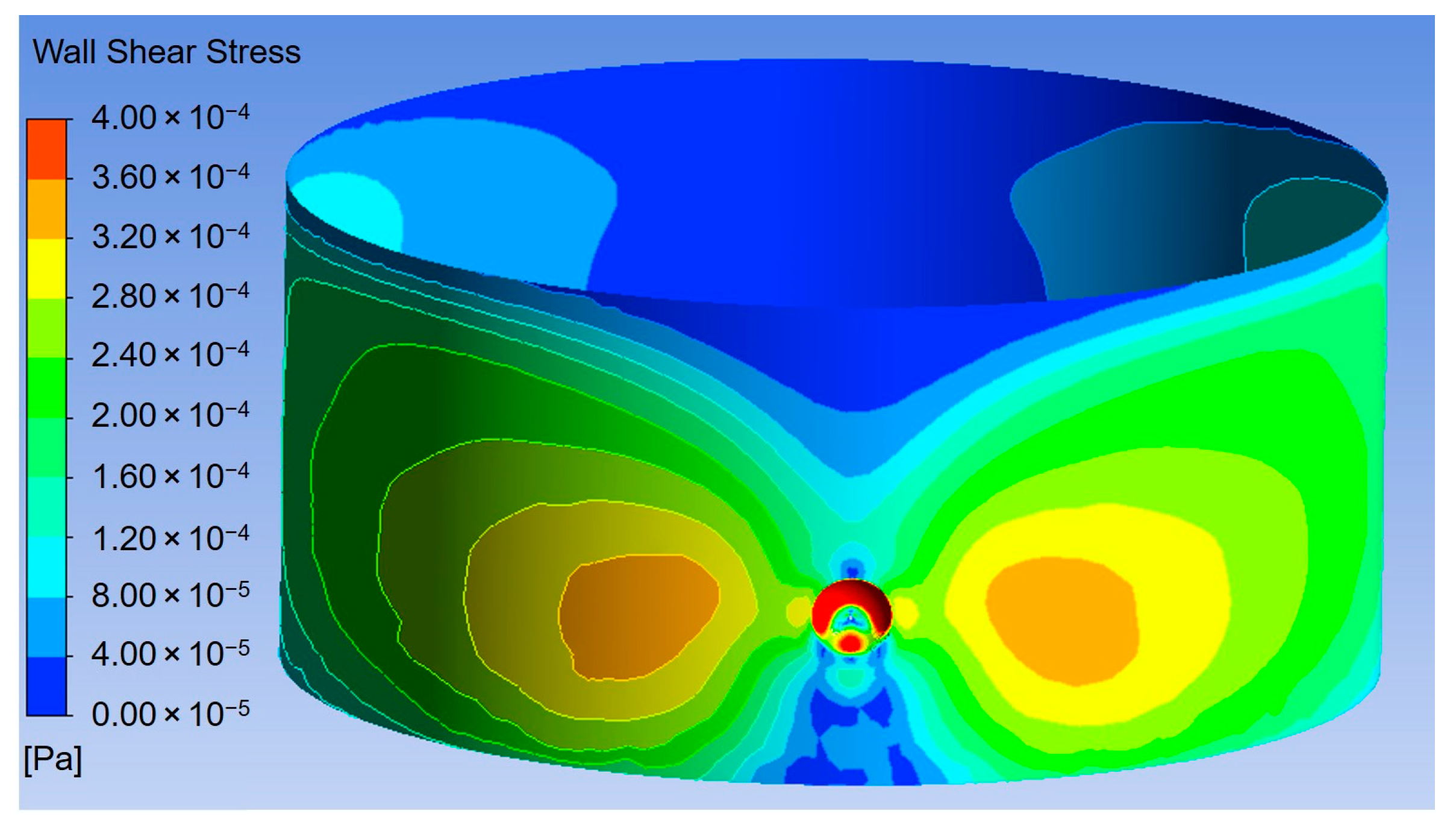
  • For WISCO’s No. 1 BF, the deadman state is “fully sitting” in the hearth. Under this influence, most of the hot metal first flows to the adjacent CFZ and then flows circumferentially through the CFZ to the taphole. The iron circulation flow causes shear stress on the hearth sidewall. The higher wall shear stress is located near the taphole within the azimuthal angle range of 0–20° and below the taphole within about 1.0 m. In contrast, the average iron velocity near the hearth bottom is quite low and the corresponding shear stress can be negligible.
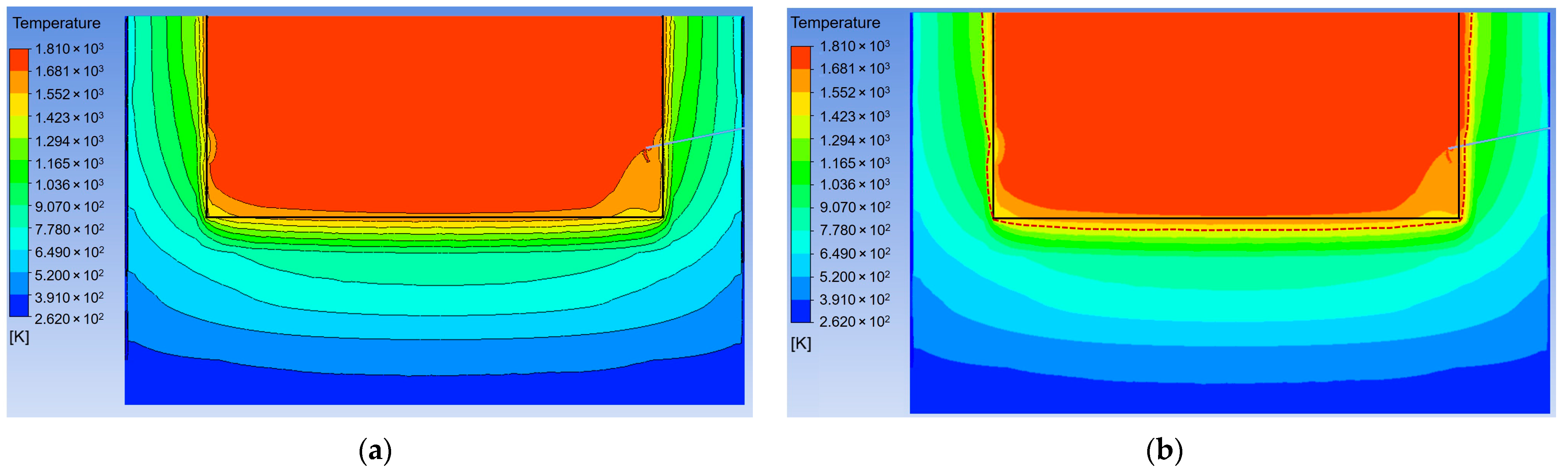
  • The 1423 K isotherm is located inside the hearth lining, indicating the potential thermal erosion risk of the hearth. The erosion depth in the hearth sidewall gradually increases with the hearth height. The erosion depth in the hearth bottom gradually increases from the hearth corner section to the central section.
  • Based on the empirical expressions obtained by the multiple linear regressions, the erosion depth in the hearth bottom is largely dependent on the temperature compared to the wall shear stress, while the erosion depth in the hearth sidewall is more dependent on the wall shear stress than the temperature.
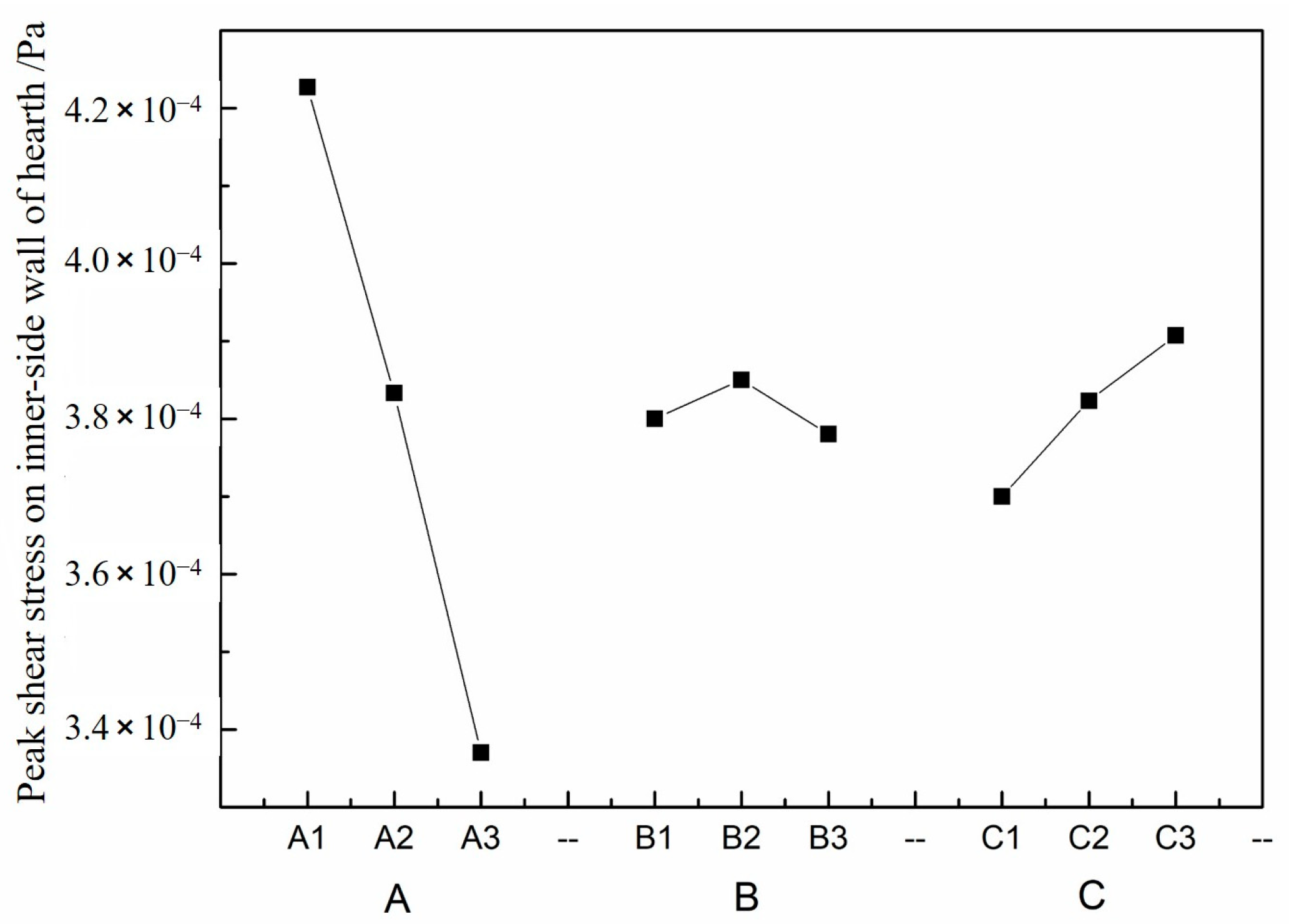
  • The taphole depth has a great influence on the shear stress on the hearth sidewall. The peak wall shear stress decreases significantly with the increase in the taphole depth. With the increase in the taphole inclination, the peak wall shear stress increases moderately. The effect of taphole size on the wall shear stress is not significant.
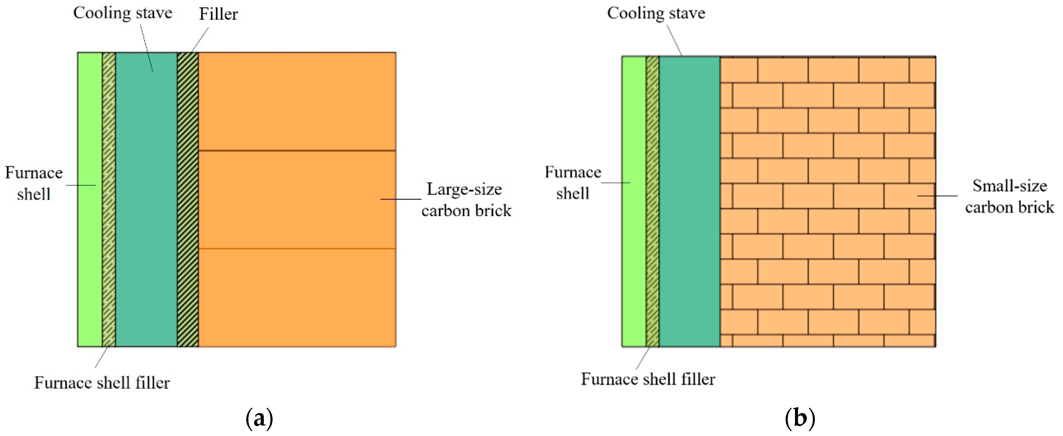
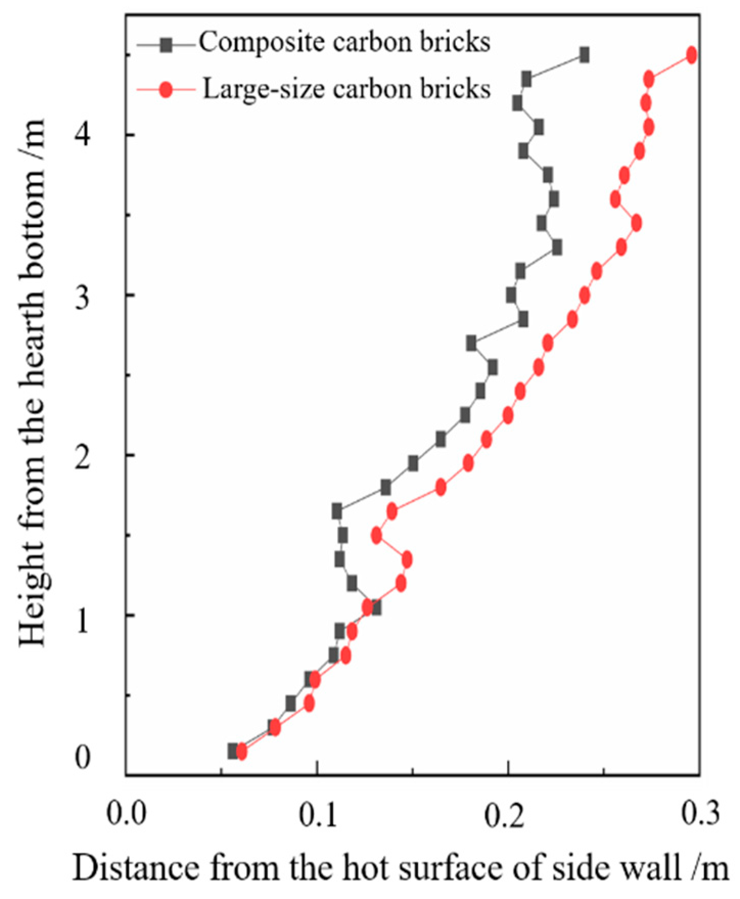
  • For the hearth with a composite carbon brick structure, the 1423 K isotherm is closer to the hot surface of the hearth sidewall compared with the hearth with the traditional large-size carbon brick structure. This indicates that the heat transfer effect of the former hearth structure is better than that of the latter one.
  • The wall shear stress and 1423 K isotherm are two key indices reflecting the hearth erosion risk of a BF. Based on the additional simulation work for the WISCO No. 6 BF, which has a similar hearth structure and deadman state to the No. 1 BF but with a larger effective volume and a higher daily productivity, the average wall shear stress is 12.5% larger than that of the No. 1 BF hearth and the 1423 K isotherm in the sidewall and bottom sections is also deeper by an average of 0.03 m and 0.05 m, respectively. This indicates that for a larger BF, the hearth erosion risk due to both mechanical and thermal erosion mechanisms may be more severe than for a smaller BF.

Author Contributions

Conceptualization, C.L. and W.Z.; literature search, A.N; study design, A.N., Z.X. (Zhixin Xiao), D.L. and Z.X. (Zhengliang Xue); data analysis, A.N., Z.X. (Zhixin Xiao) and D.L.; data interpretation, C.L. and Z.X. (Zhengliang Xue); validation, Z.X. (Zhixin Xiao) and D.L.; resources, Z.X. (Zhengliang Xue); writing—original draft preparation, A.N.; writing—review and editing, C.L. and W.Z.; project administration, W.Z. All authors have read and agreed to the published version of the manuscript.

Funding

This research was funded by the National Natural Science Foundation of China, grant number 52104340, and the China Postdoctoral Science Foundation, grant number 2020M672425.

Institutional Review Board Statement

Not applicable.

Informed Consent Statement

Not applicable.

Data Availability Statement

Not applicable.

Conflicts of Interest

The authors declare no conflict of interest.

References

  1. Naito, M.; Takeda, K.; Matsui, Y. Ironmaking technology for the last 100 years: Deployment to advanced technologies from introduction of technological know-how, and evolution to next-generation process. ISIJ Int. 2015, 55, 7–35. [Google Scholar] [CrossRef] [Green Version]
  2. Wang, C.Y.; Chiu, C.L.; Tsai, K.Y.; Chen, P.K.; Peng, P.C.; Wang, H.L. Inspecting the current thickness of a refractory wall inside an operational blast furnace using the impact echo method. NDT E Int. 2014, 66, 43–51. [Google Scholar] [CrossRef]
  3. Jiao, K.X.; Zhang, J.L.; Liu, Z.J.; Chen, C.L.; Liu, Y.X. Analysis of blast furnace hearth sidewall erosion and protective layer formation. ISIJ Int. 2016, 56, 1956–1963. [Google Scholar] [CrossRef] [Green Version]
  4. Li, Y.L.; Cheng, S.S.; Zhang, P.; Zhou, S.H. Sensitive influence of floating state of blast furnace deadman on molten iron flow and hearth erosion. ISIJ Int. 2015, 55, 2332–2341. [Google Scholar] [CrossRef] [Green Version]
  5. Komiyama, K.M.; Guo, B.Y.; Zughbi, H.; Zulli, P.; Yu, A.B. Improved CFD model to predict flow and temperature distributions in a blast furnace hearth. Metall. Mater. Trans. B 2014, 45, 1895–1914. [Google Scholar] [CrossRef]
  6. Cheng, W.T.; Huang, E.N.; Du, S.W. Numerical analysis on transient thermal flow of the blast furnace hearth in tapping process through CFD. Int. Commun. Heat Mass 2014, 57, 12–21. [Google Scholar] [CrossRef]
  7. Wang, P.; Bie, W. Numerical simulation of flow field of hot metal for hearth of blast furnace. Met. Mater. Metall. Eng. 2011, 39, 16–21. [Google Scholar]
  8. Shao, L.; Saxén, H. Numerical prediction of iron flow and bottom erosion in the blast furnace hearth. Steel Res. Int. 2012, 83, 878–885. [Google Scholar] [CrossRef]
  9. Song, F.B. Numerical Simulation of the Effect of Hot Metal Flow and Shear Stress on Blast Furnace; Northeastern University: Boston, MA, USA, 2013. [Google Scholar]
  10. Lai, P.C.; Du, S.W.; Liu, S.H.; Cheng, W.T. Numerical investigation on effects of cooling water temperature and deadman status on thermal flow in the hearth of blast furnace during tapping shutdown. Therm. Sci. Eng. Prog. 2021, 23, 100908. [Google Scholar] [CrossRef]
  11. Guo, B.Y.; Yu, A.B.; Zulli, P.; Maldonado, D. CFD modeling and analysis of the flow, heat transfer and mass transfer in a blast furnace hearth. Steel Res. Int. 2011, 82, 579–586. [Google Scholar] [CrossRef]
  12. Chang, C.M.; Cheng, W.T.; Huang, C.E.; Du, S.W. Numerical prediction on the erosion in the hearth of a blast furnace during tapping process. Int. Commun. Heat. Mass. 2009, 36, 480–490. [Google Scholar] [CrossRef]
  13. Zhou, C.Q.; Huang, D.; Zhao, Y.F.; Chaubal, P. Computational fluid dynamics analysis of 3D hot metal flow characteristics in a blast furnace hearth. J. Therm. Sci. Eng. Appl. 2010, 2, 011006. [Google Scholar] [CrossRef]
  14. Jiao, K.X.; Zhang, J.L.; Hou, Q.F.; Liu, Z.J.; Wang, G.W. Analysis of the relationship between productivity and hearth wall temperature of a commercial blast furnace and model prediction. Steel Res. Int. 2017, 88, 1600475. [Google Scholar] [CrossRef]
  15. Saxén, H. Model of draining of the blast furnace hearth with an impermeable zone. Metall. Mater. Trans. B 2015, 46, 421–431. [Google Scholar] [CrossRef]
  16. Liang, W.Q. Numerical Simulation of the Effect of Dead-Man on the Flow of Iron; North China University of Science and Technology: Boston, MA, USA, 2019. [Google Scholar]
  17. Shao, L.; Xiao, Q.L.; Zhang, C.B.; Zou, Z.S.; Saxén, H. Dead-man behavior in the blast furnace hearth—A brief review. Processes 2020, 8, 1335. [Google Scholar] [CrossRef]
  18. Zhu, J.F.; Cheng, S.S.; Zhao, H.B.; Zhang, L. Effect of deadman state on the residual rate of slag in a blast furnace hearth. J. Univ. Sci. Technol. Beijing 2009, 31, 224–228. [Google Scholar]
  19. Zhu, J.F.; Zhao, H.B.; Cheng, S.S.; Pan, H.W. Force analysis and calculation of deadman in a blast furnace hearth. J. Univ. Sci. Technol. Beijing 2009, 31, 906–911. [Google Scholar]
  20. Menter, F.R. Two-equation eddy-viscosity turbulence models for engineering applications. AIAA J. 2012, 32, 1598–1605. [Google Scholar] [CrossRef] [Green Version]
  21. Li, Y.; Chen, L.Y.; Ma, J.C. Numerical study on the relationship between the localized depression erosion of a commercial blast furnace hearth lining and the heat flux of cooling staves. IEEE Access. 2019, 7, 60984–60994. [Google Scholar] [CrossRef]
  22. Swartling, M.; Sundelin, B.; Tilliander, A.; Jonsson, P.G. Heat transfer modelling of a blast furnace hearth. Steel Res. Int. 2010, 81, 186–196. [Google Scholar] [CrossRef]
  23. Zhao, Y.F.; Fu, D.; Lherbier, L.W.; Chen, Y.; Zhou, C.Q.; Grindey, J.G. Investigation of skull formation in a blast furnace hearth. Steel Res. Int. 2014, 85, 891–901. [Google Scholar] [CrossRef]
  24. Jiao, K.X.; Zhang, J.L.; Liu, Z.J.; Xu, M.; Liu, F. Formation mechanism of the protective layer in a blast furnace hearth. Int. J. Min. Met. Mater. 2015, 22, 1017–1024. [Google Scholar] [CrossRef]
  25. Andreev, K.; Louwerse, G.; Peeters, T.; van der Stel, J. Blast furnace campaign extension by fundamental understanding of hearth processes. Ironmak. Steelmak. 2017, 44, 81–91. [Google Scholar] [CrossRef]
  26. Dong, X.F.; Zulli, P. Prediction of blast furnace hearth condition: Part I–a steady state simulation of hearth condition during normal operation. Ironmak. Steelmak. 2020, 47, 1–9. [Google Scholar] [CrossRef]
  27. Che, Y.M.; Wang, L.; Chen, L.Y. Regression analysis of the heat balance thickness of a blast furnace hearth lining. J. Phys. Conf. Ser. 2021, 1985, 1–8. [Google Scholar] [CrossRef]
  28. Inada, T.; Kasai, A.; Nakano, K.; Komatsu, S.; Ogawa, A. Dissection investigation of blast furnace hearth-kokura No. 2 blast furnace (2nd campaign). ISIJ Int. 2009, 49, 470–478. [Google Scholar] [CrossRef] [Green Version]
  29. Deng, Y.; Zhang, J.L.; Jiao, K.X. Economical and efficient protection for blast furnace hearth. ISIJ Int. 2018, 58, 1198–1203. [Google Scholar] [CrossRef] [Green Version]
  30. Ji, L.J.; Si, Y.F.; Liu, H.F.; Song, X.L.; Zhu, W.; Zhu, A.P. Application of orthogonal experimental design in synthesis of mesoporous bioactive glass. Microporous Mesoporous Mat. 2014, 184, 122–126. [Google Scholar] [CrossRef]
  31. Shan, W.F.; Wu, L.M.; Tao, N.Z.; Chen, Y.W.; Guo, D.C. Optimization method for green SrAl2O4: Eu2+, Dy3+ phosphors synthesized via co-precipitation route assisted by microwave irradiation using orthogonal experimental design. Ceram. Int. 2015, 41, 15034–15040. [Google Scholar] [CrossRef]
  32. Yang, P.Z.; Tan, X.; Sun, H.C.; Chen, D.H.; Li, C. Fire accident reconstruction based on LES field model by using orthogonal experimental design method. Adv. Eng. Softw. 2011, 42, 954–962. [Google Scholar] [CrossRef]
  33. Lu, Z.D.; Xiang, W.G.; Gu, H.Z.; Huang, A.; Fu, L.P. Structural innovation of refractory materials for blast furnace hearth of WISCO. Refractories 2019, 53, 468–471. [Google Scholar]
Figure 1. The geometric model of the hearth of the WISCO No. 1 BF. 1 Deadman, 2 Coke-free zone, 3 Ceramic cup, 4 Semi-graphite carbon brick, 5–6 Micropore carbon brick, 7 Semi-graphite carbon brick, 8 Ramming filler, 9 Cast iron cooling stave, 10 Furnace shell, 11 Furnace shell filler.
Metals 12 00843 g001
Figure 2. Schematic diagram of the 3-D simulated hearth structure of the WISCO No. 1 BF.
Metals 12 00843 g002
Figure 3. (a) Iron flow field in the xz cross section through the taphole line and (b) iron flow field in the xy cross section with 1.5 m height from the hearth bottom. The CFZ is marked by black lines.
Metals 12 00843 g003
Figure 4. Shear-stress distributions on (a): the inner-sidewall and (b): the bottom of the hearth.
Metals 12 00843 g004
Figure 5. Shear-stress distributions on the inner-sidewall at the height of (a) 0.5 m, (b) 1.5 m, and (c) 2.5 m from the hearth bottom.
Metals 12 00843 g005
Figure 6. (a) Hearth temperature field in the xz cross section; (b) position of 1423 K isotherm.
Metals 12 00843 g006
Figure 7. Measured erosion profile on the hearth cross section near No. 97 water pipe of the WISCO No. 1 BF.
Metals 12 00843 g007
Figure 8. Iron flow fields of No. 7 case: (a) in the xz cross section through taphole and (b) in the xy cross section with 1.5 m height from the hearth bottom.
Metals 12 00843 g008
Figure 9. Shear-stress distributions on the inner-sidewall at a height of 1.5 m from the hearth bottom. (a) Original No. 1 BF case; (b) No. 7 Case.
Metals 12 00843 g009
Figure 10. Shear-stress distribution on the inner-sidewall of the hearth in the No. 7 case.
Metals 12 00843 g010
Figure 11. Peak wall shear stress corresponding to each level of each iron tapping factor.
Metals 12 00843 g011
Figure 12. Schematic diagrams of the hearth structures with (a) large-size carbon bricks and (b) small-size carbon bricks.
Metals 12 00843 g012
Figure 13. Schematic diagram of the hearth structure using composite carbon bricks.
Metals 12 00843 g013
Figure 14. 1423 K isotherm line on the xz cross section of hearth sidewall through the taphole.
Metals 12 00843 g014
Table 1. Main geometric design parameters of WISCO No. 1 BF.
Effective Volume (m3)Hearth Diameter (m)Throat Diameter (m)Number of TuyeresDepth of Raceway Zone (m)Distance from Taphole to Tuyere (m)Stockline Height (m)
220010.77.8261.23.71.6
Table 2. Main operating parameters of WISCO No. 1 BF.
ParametersUnitValue
Coke ratiokg·tHM−1330
Pressure losskPa160
Iron ore grade%59
Descending speed of charging materialmm·s−11.0
Average size of charging materialm0.02
Molten iron densitykg·m−37000
Iron ore densitykg·m−33520
Coke densitykg·m−3990
Blast speedm/s230
Deadman voidage%31
Table 3. Main geometrical parameters of the hearth of WISCO No. 1 blast furnace.
Hearth Diameter (m)Diameter of Deadman Bottom (m)Deadman Inclination (°)Hearth Height (m)Distance between Taphole and Hearth Bottom (m)Taphole Inclination (°)Taphole Size (mm)
10.79.7804.52.011.550
Table 4. Main physical parameters of hot metal and coke.
MaterialDensity
(kg·m−3)
Viscosity
(Pa·s)
Heat Capacity
(J·kg−1·K−1)
Thermal Conductivity (W·m−1·K−1)
Hot metal70000.00885016.5
Coke99015502.5
Table 5. Main thermal parameters of refractory materials.
Thermal ParametersCeramic CupSemi-Graphite Carbon BrickMicro-Pore Carbon BrickRamming FillerCast Iron Cooling StaveFurnace Shell FillerFurnace Shell
Heat capacity
/J·kg−1·K−1
495502.5460.6310500300520
Heat conductivity
/W·m−1·K−1
3.5101510500.340
Table 6. Orthogonal design table for the iron tapping optimization and the corresponding peak wall shear stress for each simulation case.
Simulation Case No.Taphole Depth
(m)
Taphole Size
(mm)
Taphole Inclination (°)Peak Wall Shear Stress (Pa)
12.75011.54.14 × 10−4
22.75513.54.35 × 10−4
32.76012.54.19 × 10−4
42.95013.53.90 × 10−4
52.95512.53.92 × 10−4
62.96011.53.68 × 10−4
73.15012.53.36 × 10−4
83.15511.53.28 × 10−4
93.16013.53.47 × 10−4
Table 7. Features of the hearth refractory structures using the large-size and small-size carbon bricks [33].
TypeAdvantageDisadvantage
Large-size carbon brickSimpler hearth construction with fewer brickwork joints; better integrity of hearth lining structure, which helps resist the physical and chemical erosions of the hot metal.The ramming filler between the cooling stave and the carbon bricks affects the heat conductivity; the temperature difference between the hot and cold surfaces of the carbon bricks is large.
Small-size carbon brickBetter overall heat conductivity of hearth structure; no ramming filler between the cooling stave and the carbon bricks.Complex hearth construction with more brickwork joints in the hearth lining, which makes the wall surface more susceptible to the erosion of hot metal.
Publisher’s Note: MDPI stays neutral with regard to jurisdictional claims in published maps and institutional affiliations.

