
Investigation of the Interface between Laser-Melted CoCr and a Stainless Steel Substrate

 , , ,
, , ,  and
and 
Abstract
:1. Introduction
2. Materials and Methods
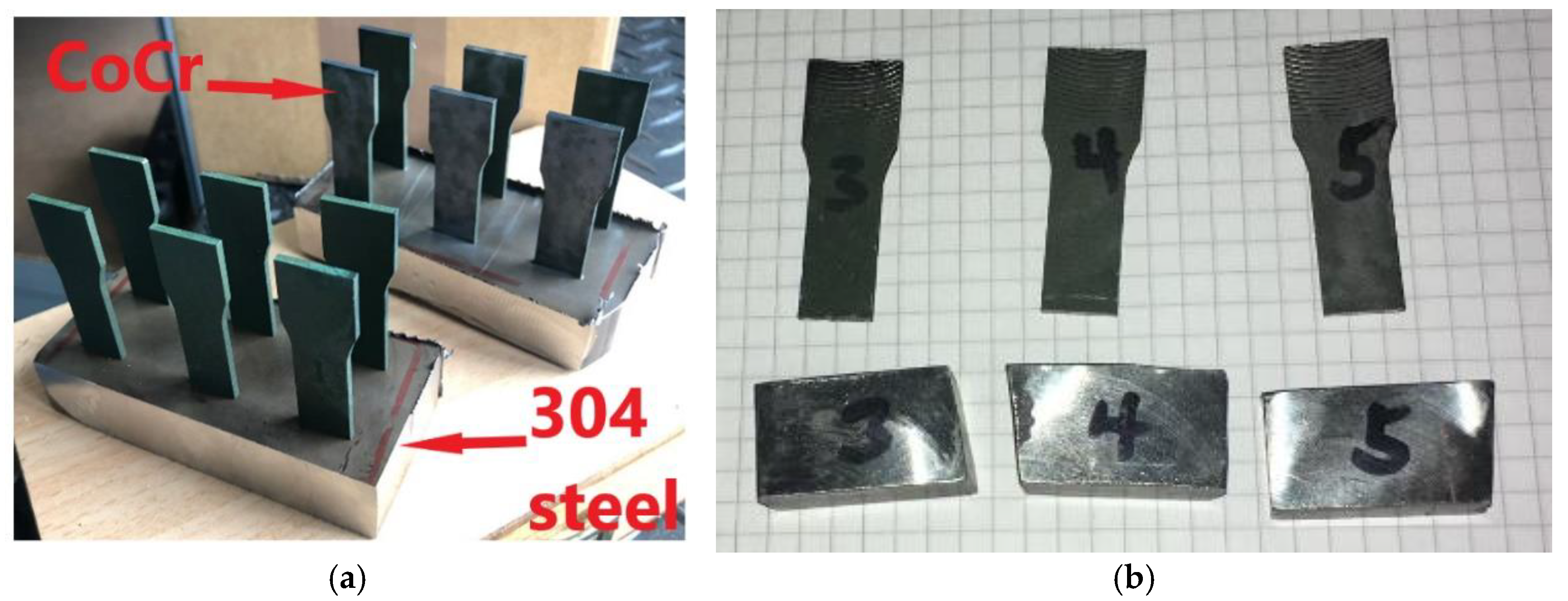
2.1. Materials and Specimen Design
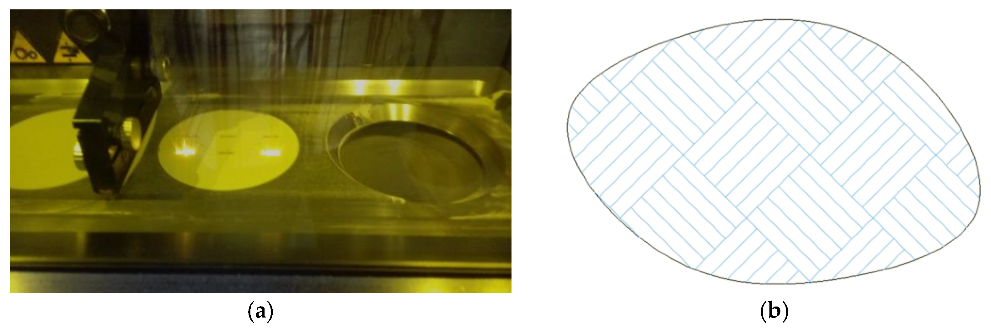
2.2. SLM Parameters
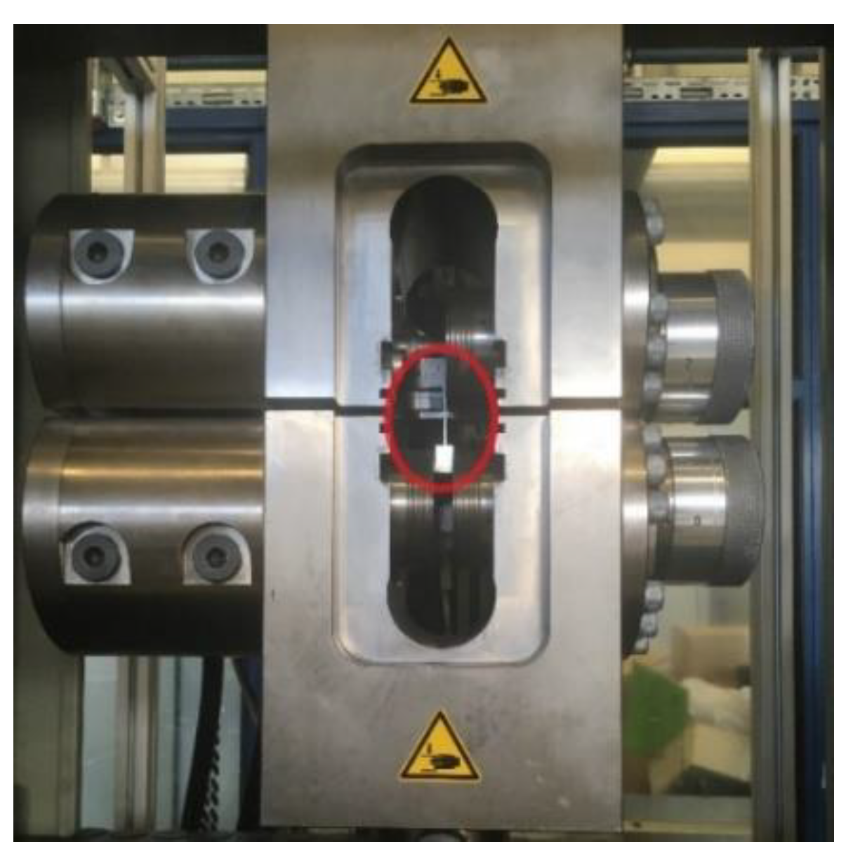
2.3. Mechanical Properties
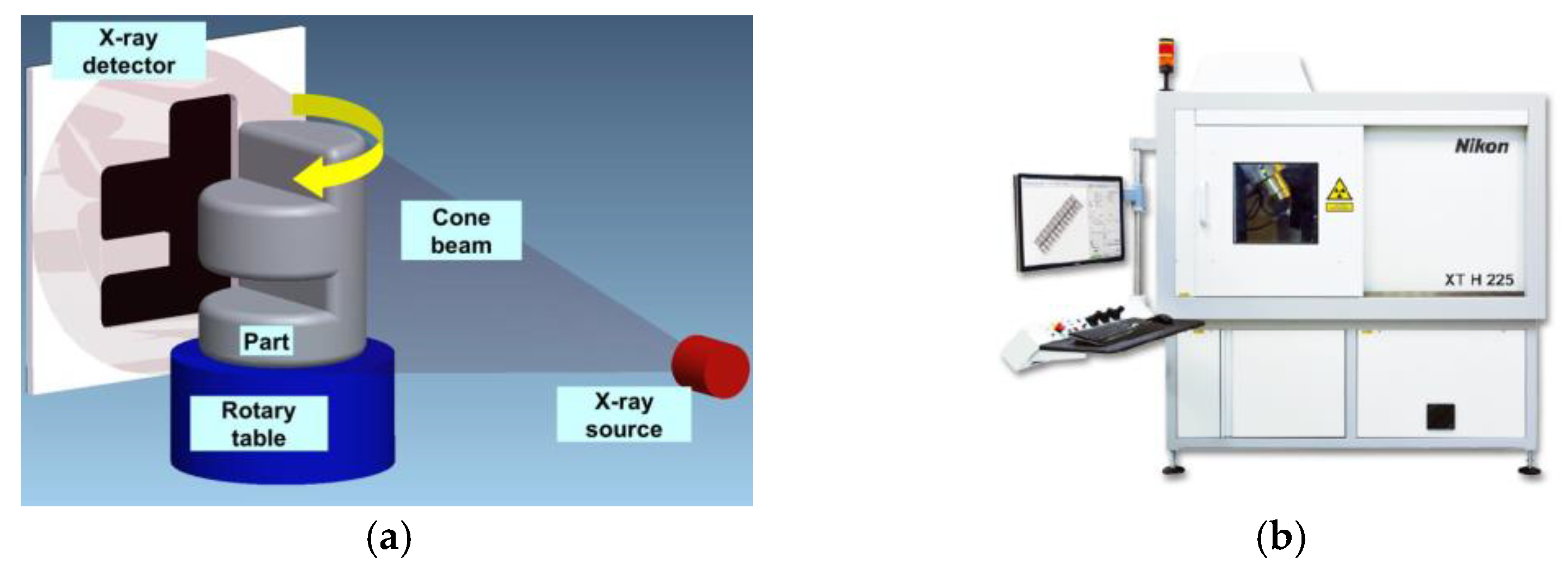
2.4. CT Scanning
2.5. SEM, EDAX, and XRD
3. Results
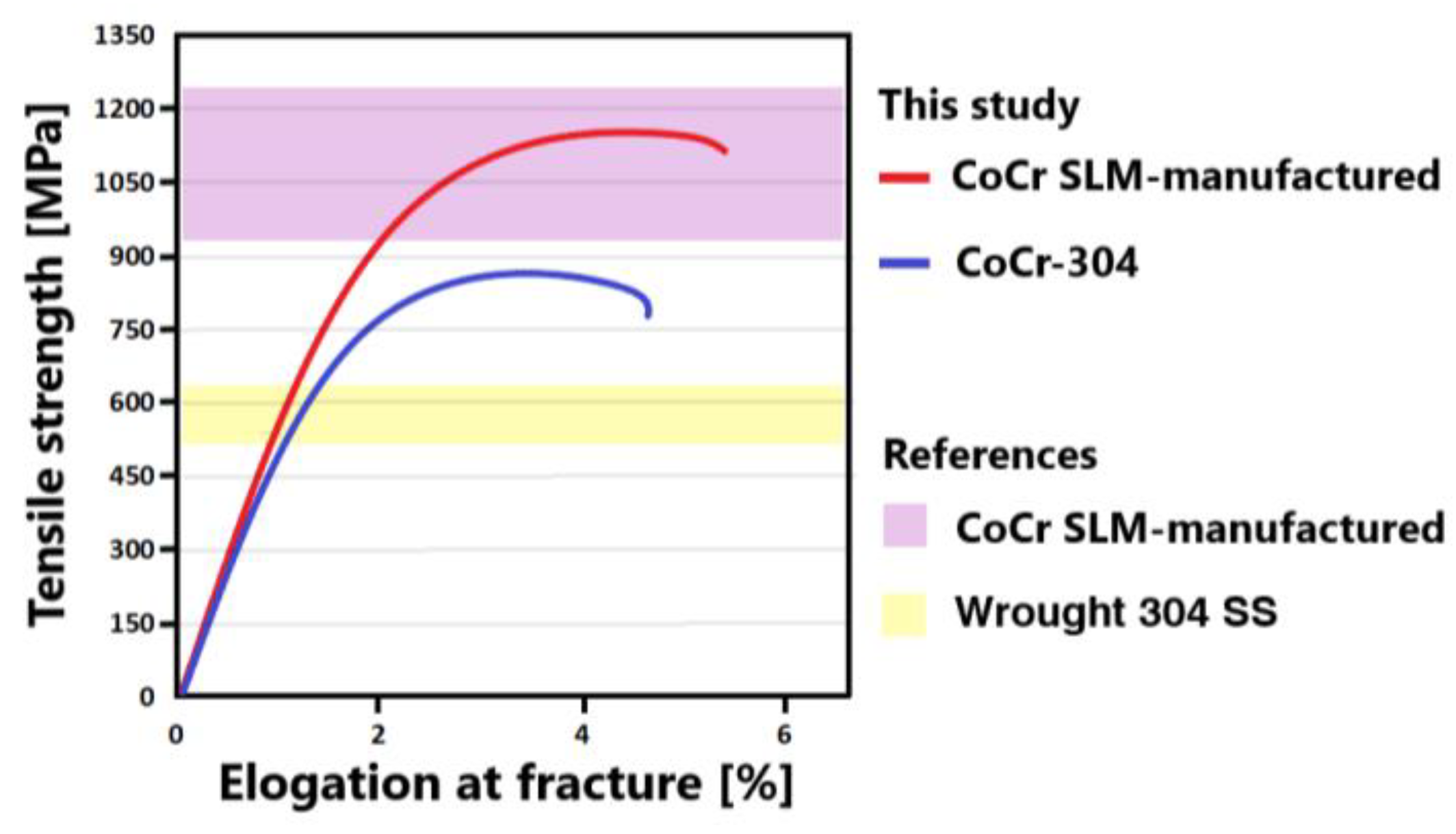
3.1. Mechanical Response of the CoCr–304 Interface
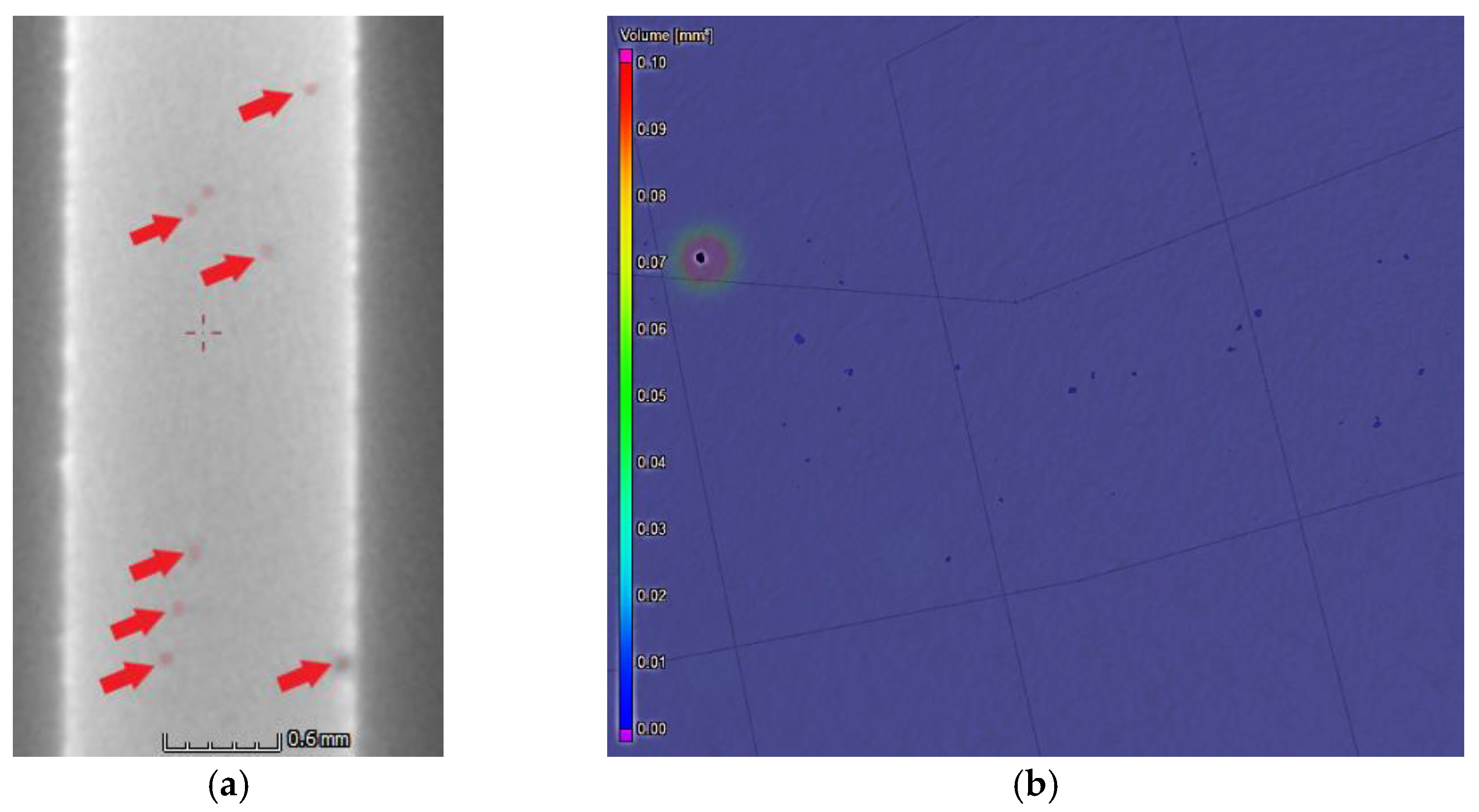
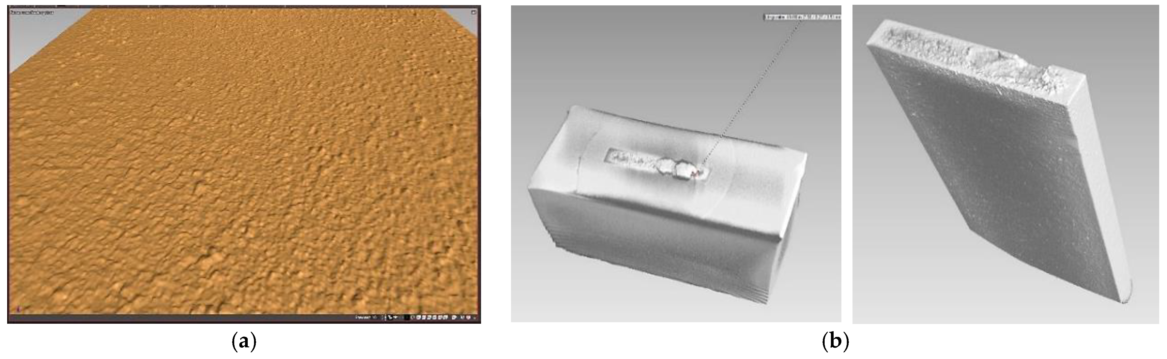
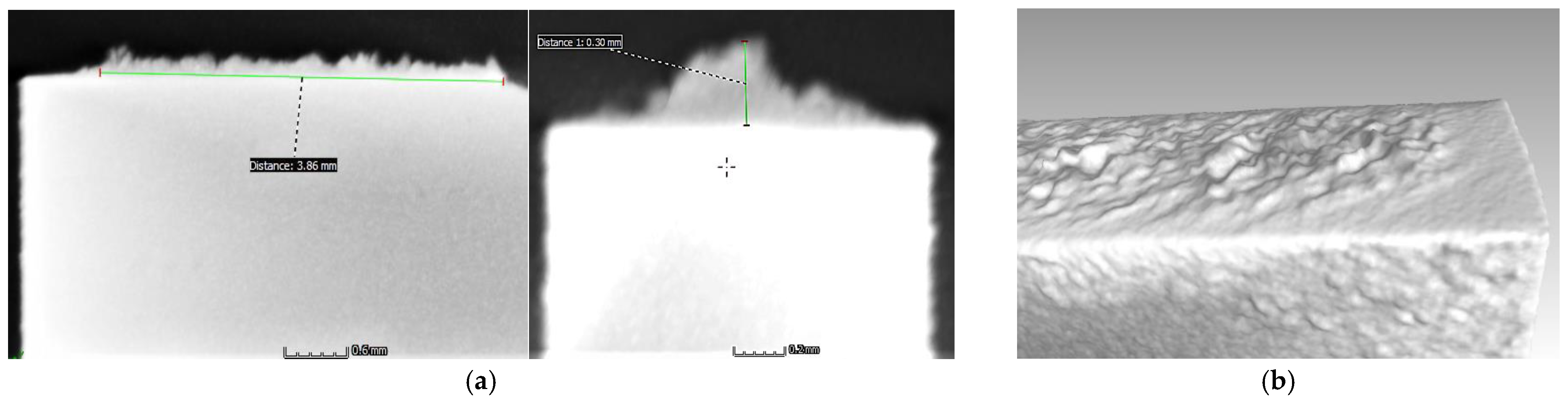
3.2. CT
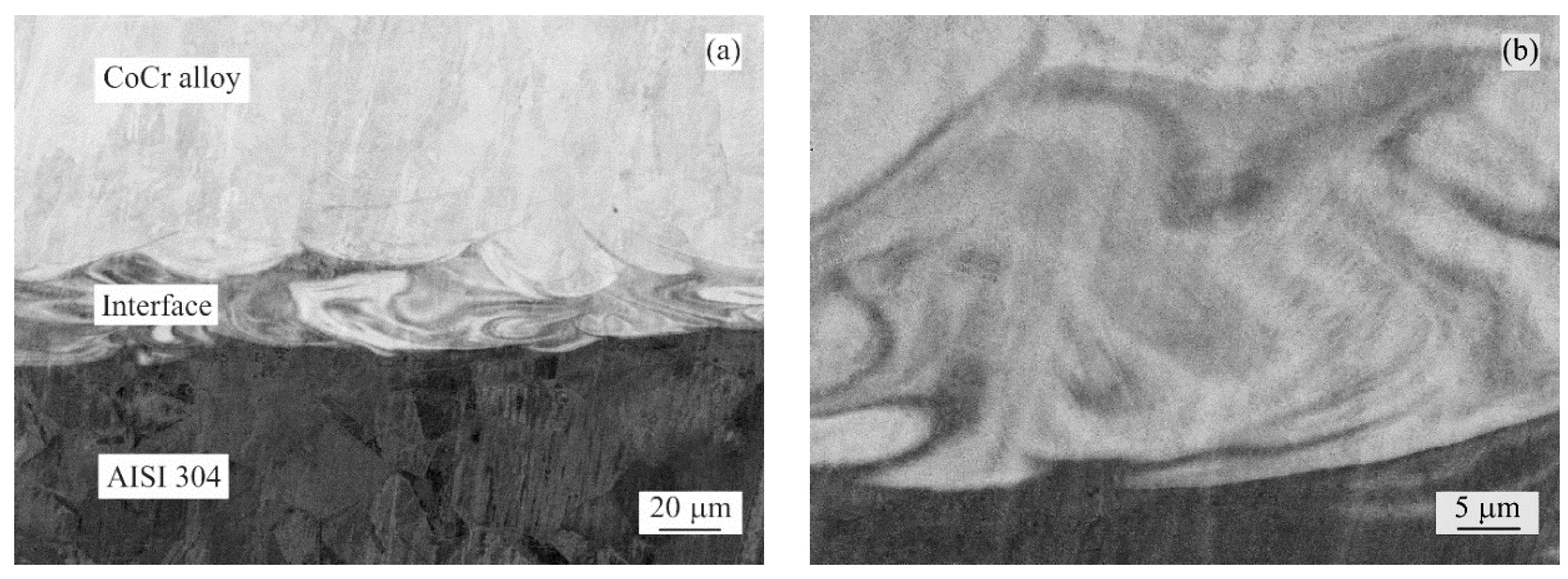
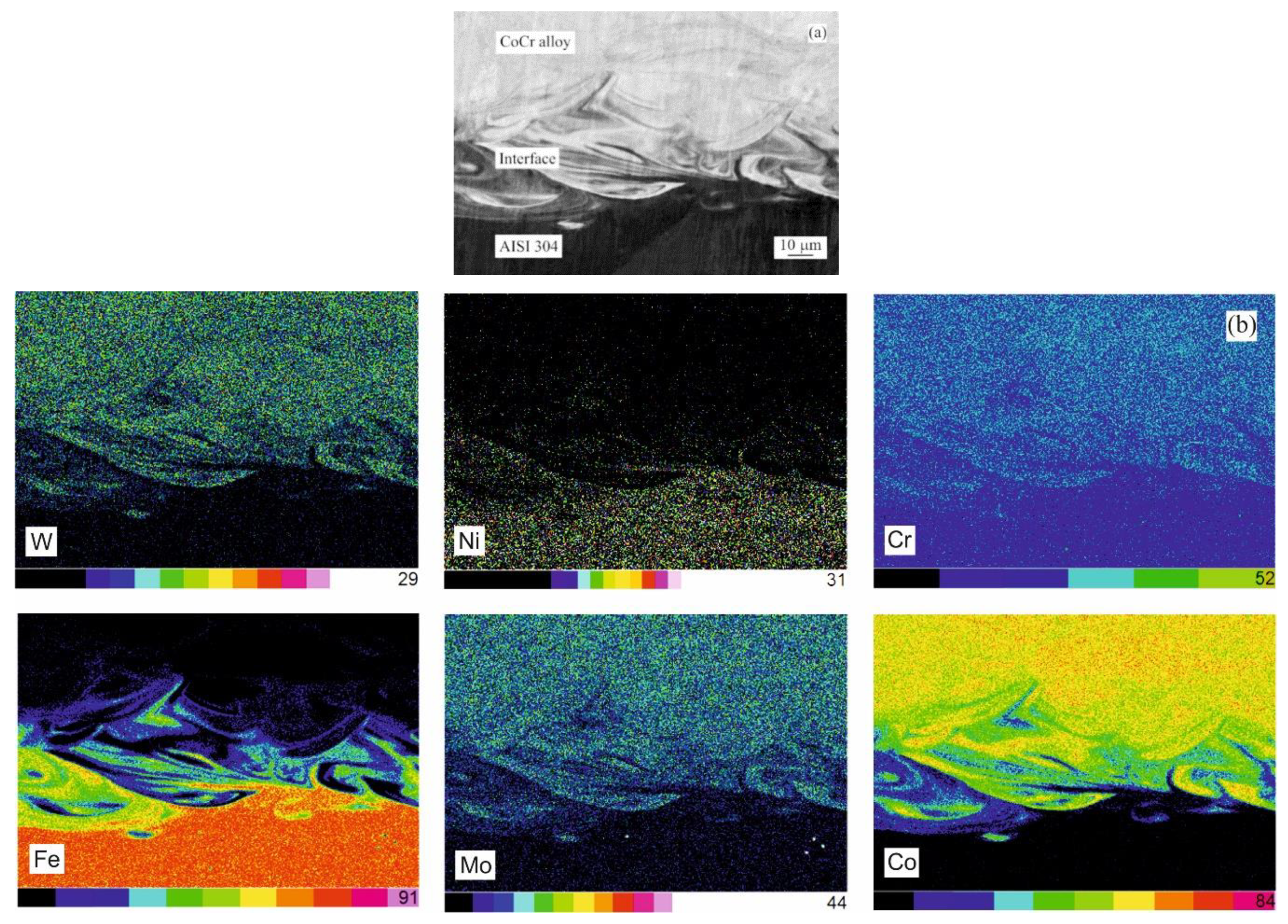
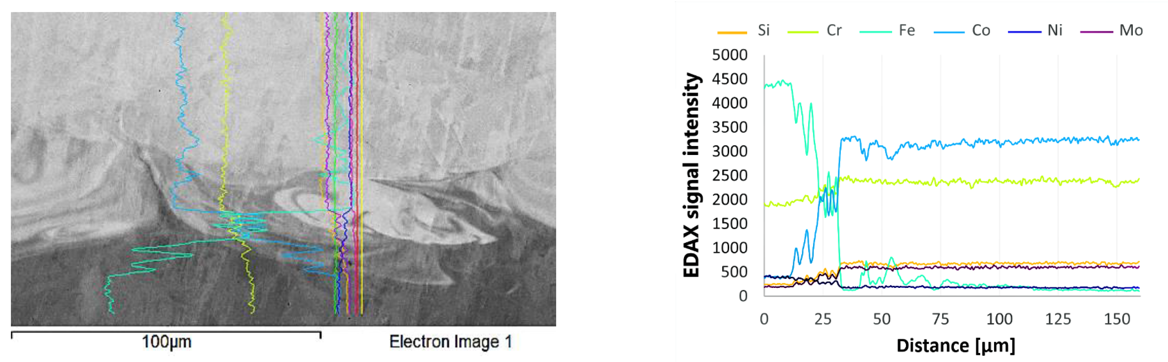
3.3. Microstructure of the CoCr–304 Interface
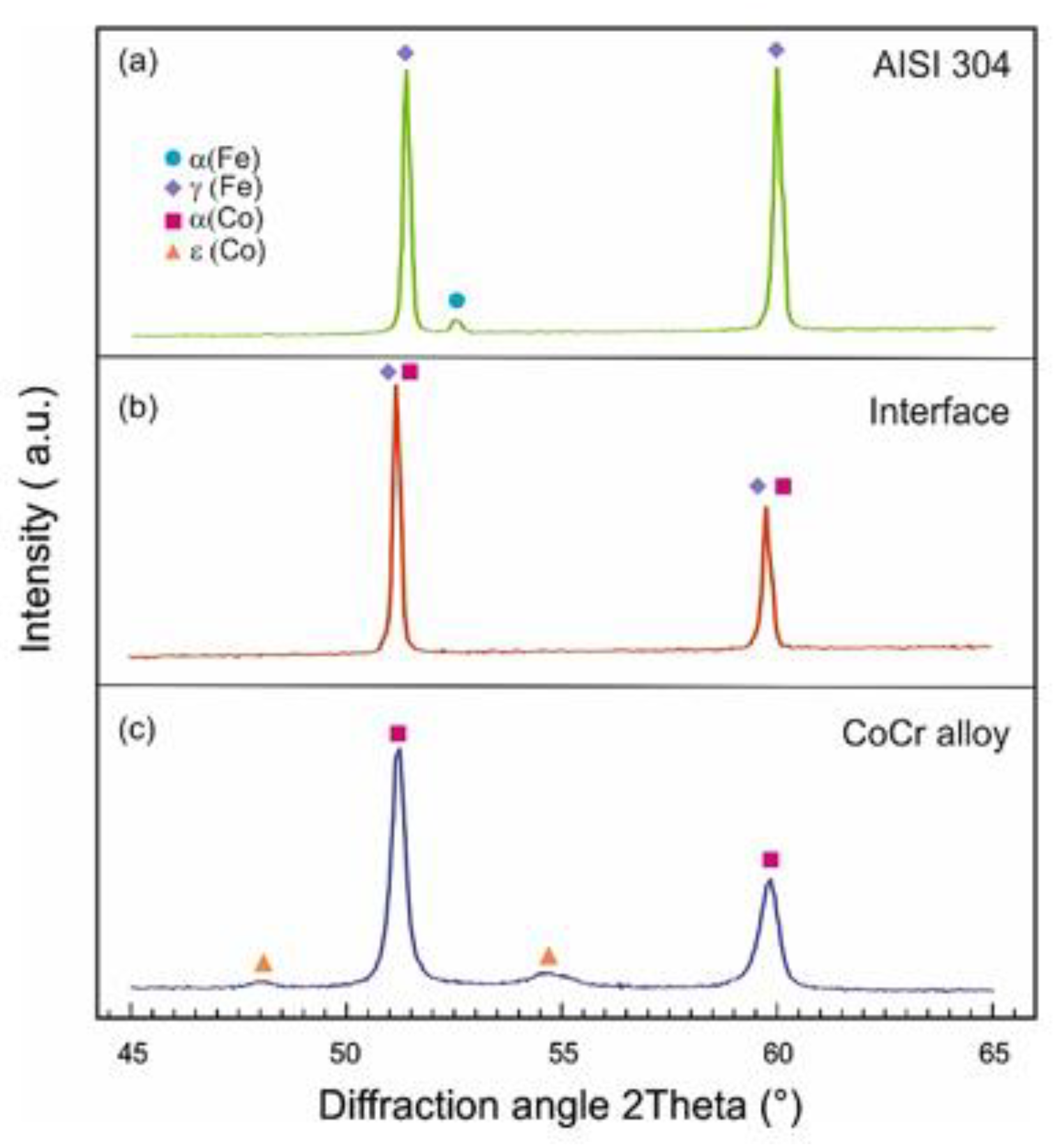
3.4. XRD
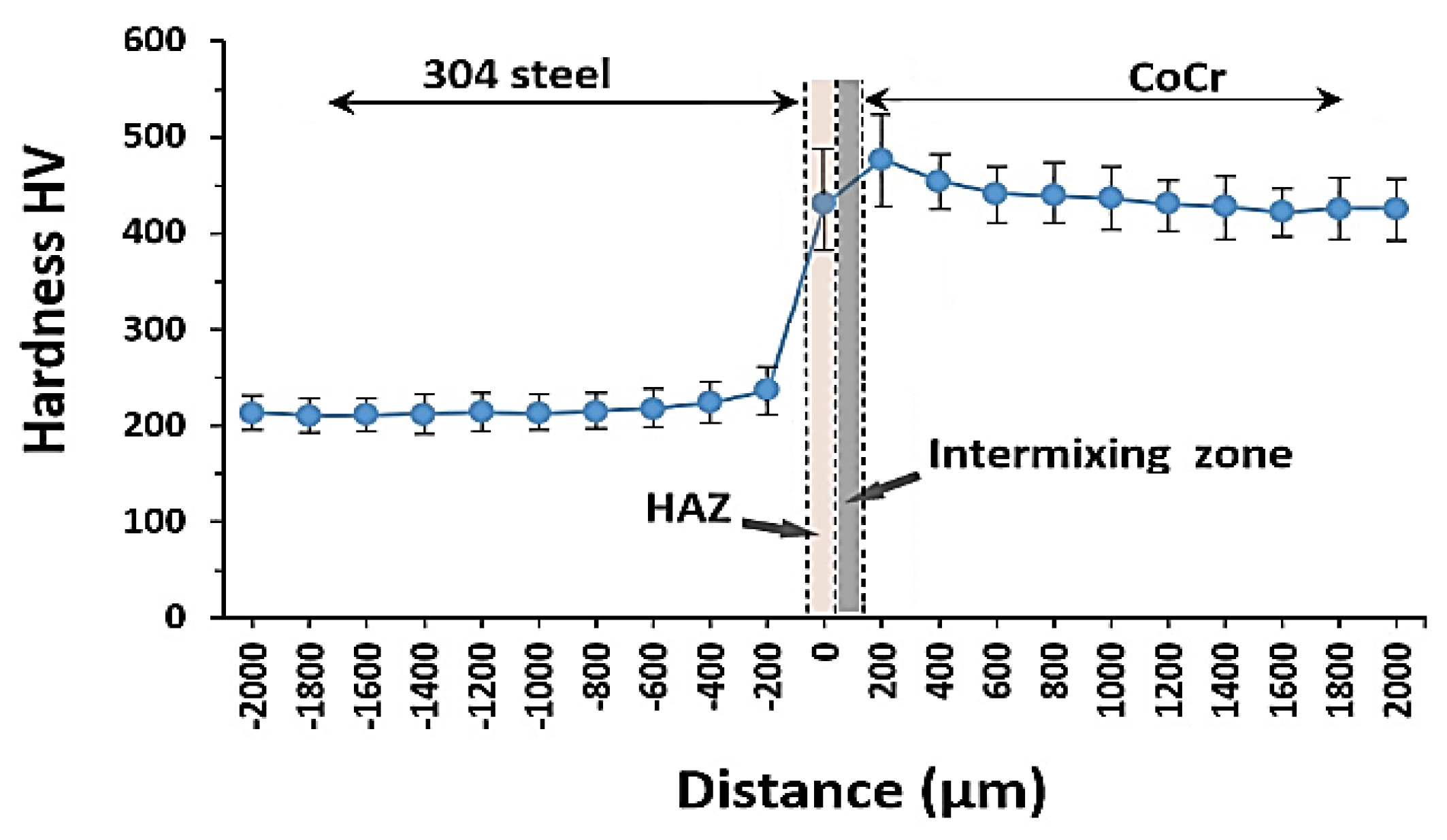
3.5. Hardness Measurements
4. Discussion
5. Conclusions
Author Contributions
Funding
Data Availability Statement
Conflicts of Interest
References
- Lachmayer, R.; Lippert, R.B.; Fahlbusch, T. 3D-Druck Beleuchtet—Additive Manufacturing auf dem Weg in die Anwendung; Springer: Berlin/Heidelberg, Germany, 2016; ISBN 978-3-662-49055-6. [Google Scholar]
- Zghair, Y.A.; Lachmayer, R. Additive repair design approach: Case study to repair aluminium base components. In Proceedings of the 21st International Conference on Engineering Design, Vancouver, BC, Canada, 21–25 August 2017. [Google Scholar]
- Zhang, X.; Pan, T.; Li, W.; Liou, F. Experimental Characterization of a Direct Metal Deposited Cobalt-Based Alloy on Tool Steel for Component Repair. JOM 2019, 71, 946–955. [Google Scholar] [CrossRef]
- Xie, W.; Jiang, W.; Wu, Y.; Song, H.; Deng, S.; Lăzărescu, L.; Zhang, S.; Banabic, D. Process parameter optimization for thin-walled tube push-bending using response surface methodology. Int. J. Adv. Manuf. Technol. 2022, 118, 3833–3847. [Google Scholar] [CrossRef]
- Sebastian, R.; Singh, A.K.; Paliwal, M.; Gautam, A. Investigation of the interface between SLM processed nickel alloy on a cast iron substrate. Prog. Addit. Manuf. 2019, 4, 131–142. [Google Scholar] [CrossRef]
- Liu, Q.; Djugum, R.; Sun, S.; Walker, K.; Choi, Y.; Brandt, M. Repair and manufacturing of military aircraft components by additive manufacturing technology. In Proceedings of the 17th Australian Int. Aerospace Congress (AIAC 2017), Melbourne, VIC, Australia, 26–28 February 2017; pp. 363–368. [Google Scholar]
- Marazani, T. Laser Additive Manufacturing Technology for Crack Repairs in Titanium Alloy Components. Ph.D. Thesis, University of Johannesburg, Johannesburg, South Africa, 2016. [Google Scholar]
- Marazani, T.; Madyira, D.M.; Akinlabi, E.T. Laser Re-Melt Technique for Laser Additive Repair of Narrow Rectangular Cracks in Grade 5 Titanium Alloy (Ti-6Al-4V). Key Eng. Mater. 2019, 796, 129–136. [Google Scholar] [CrossRef]
- Perini, M.; Amirabdollahian, S.; Bosetti, P. Building Multi-Material components by Direct Laser Deposition. MATEC Web Conf. 2019, 299, 01006. [Google Scholar] [CrossRef]
- Guévenoux, C.; Hallais, S.; Charles, A.; Charkaluk, E.; Constantinescu, A. Mechanical response of a Laser Cladding repaired structure: Localization of plastic strain due to microstructure gradient. MATEC Web Conf. 2019, 300, 03003. [Google Scholar] [CrossRef] [Green Version]
- Balit, Y.; Guévenoux, C.; Tanguy, A.; Upadhyay, M.; Charkaluk, E.; Constantinescu, A. High resolution digital image correlation for microstructural strain analysis of a stainless steel repaired by Directed Energy Deposition. Mater. Lett. 2020, 270, 127632. [Google Scholar] [CrossRef] [Green Version]
- Armencea, G.; Berce, C.; Rotaru, H.; Bran, S.; Stefan, V.; Leordean, D.; Jula, C.-A.; Gheban, D.; Lazar, M.; Baciut, G.; et al. Titanium alloys with hydroxyapatite or SiO2+TiO2 coatings used in bone reconstruction. J. Optoelectron. Adv. Mat. 2015, 9, 865–868. [Google Scholar]
- Zhao, D.; Huang, Y.; Ao, Y.; Han, C.; Wang, Q.; Li, Y.; Liu, J.; Wei, Q.; Zhang, Z. Effect of pore geometry on the fatigue properties and cell affinity of porous titanium scaffolds fabricated by selective laser melting. J. Mech. Behav. Biomed. Mater. 2018, 88, 478–487. [Google Scholar] [CrossRef]
- Garcia-Lopez, E.; Siller, H.R.; Rodríguez, C.A. Development of AISI 316L stainless steel coronary stent. In Laser-Based Micro-and Nanoprocessing XII; International Society for Optics and Photonics: Bellingham, WA, USA, 2018. [Google Scholar] [CrossRef]
- Grobelny, P.; Furmanski, L.; Legutko, S. Investigations of Surface Topography of Hot Working Tool Steel Manufactured with the Use of 3D Print. MATEC Web Conf. 2017, 137, 02004. [Google Scholar] [CrossRef]
- Buican, G.R.; Oancea, G.; Martins, R.F. Study on SLM manufacturing of teeth used for dental tools testing. MATEC Web Conf. 2017, 94, 03002. [Google Scholar] [CrossRef] [Green Version]
- Cosma, C.; Kessler, J.; Gebhardt, A.; Campbell, I.; Balc, N. Improving the Mechanical Strength of Dental Applications and Lattice Structures SLM Processed. Materials 2020, 13, 905. [Google Scholar] [CrossRef] [Green Version]
- Ocelik, V.; de Oliveira, U.; de Boer, M.; de Hosson, J.T.M. Thick Co-based coating on cast iron by side laser cladding: Analysis of processing conditions and coating properties. Surf. Coat. Technol. 2007, 201, 5875–5883. [Google Scholar] [CrossRef] [Green Version]
- Dak, G.; Sirohi, S.; Pandey, C. Study on microstructure and mechanical behavior relationship for laser-welded dissimilar joint of P92 martensitic and 304L austenitic steel. Int. J. Press. Vessel. Pip. 2022, 196, 104629. [Google Scholar] [CrossRef]
- Sirohi, S.; Taraphdar, P.K.; Dak, G.; Pandey, C.; Sharma, S.; Goyal, A. Study on evaluation of through-thickness residual stresses and microstructure-mechanical property relation for dissimilar welded joint of modified 9Cr–1Mo and SS304H steel. Int. J. Press. Vessel. Pip. 2021, 194, 104557. [Google Scholar] [CrossRef]
- Materials Properties of 304 Stainless Steel. Available online: http://asm.matweb.com/search/SpecificMaterial.asp?bassnum=mq304a (accessed on 1 August 2021).
- Material Data Sheet for CoCr Powder Starbond CoS 30. S&S Scheftner GmbH, Germany. Available online: www.scheftner.dental (accessed on 8 August 2021).
- Popan, I.A.; Balc, N.; Popan, A.; Fratila, D.; Trif, A. Surface roughness prediction during dry turning of austenitic stainless steel AISI 304. Appl. Mech. Mater. 2015, 808, 54–59. [Google Scholar] [CrossRef]
- Pustan, M.; Chiorean, R.; Birleanu, C.; Dudescu, C.; Muller, R.; Baracu, A.; Voicu, R. Reliability design of thermally actuated MEMS switches based on V-shape beams. Microsyst. Technol. 2017, 23, 3863–3871. [Google Scholar] [CrossRef]
- ISO 6892-1:2019; Metallic Materials—Tensile Testin—Part 1: Method of Test at Room Temperature. ISO: Geneva, Switzerland, 2019.
- Godineau, K.; Lavernhe, S.; Tournier, C. Calibration of galvanometric scan heads for additive manufacturing with machine assembly defects consideration. Addit. Manuf. 2019, 26, 250–257. [Google Scholar] [CrossRef]
- Yan, X.; Lin, H.; Wu, Y.; Bai, W. Effect of two heat treatments on mechanical properties of selective-laser-melted Co-Cr metal-ceramic alloys for application in thin removable partial dentures. J. Prosthet. Dent. 2018, 119, e1–e6. [Google Scholar] [CrossRef]
- Cosma, C.; Moldovan, M.; Simion, M.; Balc, N. Impact of laser parameters on additively manufactured cobalt-chromium restorations. J. Prosthet. Dent. 2021. [Google Scholar] [CrossRef]
- Kim, H.R.; Jang, S.H.; Kim, Y.K.; Son, J.S.; Min, B.K.; Kim, K.-H.; Kwon, T.Y. Microstructures and mechanical properties of Co-Cr dental alloys fabricated by three CAD/CAM-based processing techniques. Materials 2016, 9, 596. [Google Scholar] [CrossRef]
- Ucar, Y.; Ekren, O. Effect of layered manufacturing techniques, alloy powders, and layer thickness on mechanical properties of Co-Cr dental alloys. J. Prosthet. Dent. 2018, 120, 762–770. [Google Scholar] [CrossRef] [PubMed]
- ASTM E384-17; Standard Test Method for Microindentation Hardness of Materials. American Society for Testing and Materials: West Conshohocken, PA, USA, 2018.
- Angheluta, L.M. 3D reconstruction of archaeological artefacts from 2-D X-ray images. Optoelectron. Adv. Mater.—Rapid Commun. 2018, 12, 705–712. [Google Scholar]
- De Chiffre, L.; Carmignato, S.; Kruth, J.P.; Schmitt, R.; Weckenmann, A. Industrial applications of computed tomography. CIRP Ann. 2014, 63, 655–677. [Google Scholar] [CrossRef]
- Angel, J.A.B. Quality Assurance of CT Scanning for Industrial Applications. Ph.D. Thesis, Technical University of Denmark, Kongens Lyngby, Denmark, 2014. [Google Scholar]
- Lutterotti, L.; Matthies, S.; Wenk, H.R. MAUD (Material Analysis Using Diffraction): A user friendly Java program for rietveld texture analysis and more. In Proceedings of the 12th International Conference on Textures of Materials (ICOTOM-12), Montreal, QC, Canada, 9–13 August 1999; Available online: http://hdl.handle.net/11572/57067 (accessed on 22 August 2021).
- Zhou, Y.; Li, N.; Yan, J.; Zeng, Q. Comparative analysis of the microstructures and mechanical properties of Co-Cr dental alloys fabricated by different methods. J. Prosthet. Dent. 2018, 120, 617–623. [Google Scholar] [CrossRef]
- Liverani, E.; Balbo, A.; Monticelli, C.; Leardini, A.; Belvedere, C.; Fortunato, A. Corrosion resistance and mechanical characterization of ankle protheses fabricated via selective laser melting. Procedia CIRP 2017, 65, 25–31. [Google Scholar] [CrossRef]
- Material Data Sheet for 304 Stainless Steel. Otel Inox, Romania. Available online: www.otelinox.com/ro/products/304.asp (accessed on 3 August 2021).
- Milad, M.; Zreiba, N.; Elhalouani, F.; Baradai, C. The effect of cold work on structure and properties of AISI 304 stainless steel. J. Mater. Process. Technol. 2008, 203, 80–85. [Google Scholar] [CrossRef]
- Shojaati, M.; Beidokhti, B. Characterization of AISI 304/AISI 409 stainless steel joints using different filler materials. Constr. Build. Mater. 2017, 147, 608–615. [Google Scholar] [CrossRef]
- Hitzler, L.; Alifui-Segbaya, F.; Williams, P.; Heine, B.; Heitzmann, M.; Hall, W.; Merkel, M.; Öchsner, A. Additive Manufacturing of Cobalt-Based Dental Alloys: Analysis of Microstructure and Physicomechanical Properties. Adv. Mater. Sci. Eng. 2018, 2018, 8213023. [Google Scholar] [CrossRef] [Green Version]
- Musteata, A.E.; Pelin, G.; Botan, M.; Popescu, A.; Deleanu, L. The Behavior of Polymeric Blends (PP + PA6) in Tensile Tests. Mater. Plast. 2020, 57, 153–166. [Google Scholar] [CrossRef]
- Du Plessis, A.; Le Roux, S.G. X-ray micro-CT supporting the South African Additive Manufacturing Community. Preprints 2018, 1, 2018100534. [Google Scholar] [CrossRef] [Green Version]
- Du Plessis, A.; Sperling, P.; Beerlink, A.; Tshabalala, L.; Hoosain, S.; Mathe, N.; Le Roux, S.G. Standard method for microCT-based additive manufacturing quality control 1: Porosity analysis. Methods X 2018, 5, 1102–1110. [Google Scholar] [CrossRef]
- Čapek, J.; Machová, M.; Fousová, M.; Kubásek, J.; Vojtěch, D.; Fojt, J.; Jablonska, E.; Lipov, J.; Ruml, T. Highly porous, low elastic modulus 316L stainless steel scaffold prepared by selective laser melting. Mater. Sci. Eng. C 2016, 69, 631–639. [Google Scholar] [CrossRef] [PubMed]
- Shah, K.; Haq, I.; Khan, A. Parametric study of development of Inconel-steel functionally graded materials by laser direct metal deposition. Mater. Des. 2014, 54, 531–538. [Google Scholar] [CrossRef]
- Carroll, B.E.; Otis, R.A.; Borgonia, J.; Suh, J.O.; Dillon, P.; Shapiro, A.A.; Hofmann, D.C.; Liu, Z.K.; Beese, A.M. Functionally graded material of 304L stainless steel and Inconel 625 fabricated by directed energy deposition: Characterization and thermodynamic modeling. Acta Mater. 2016, 108, 46–54. [Google Scholar] [CrossRef] [Green Version]
- Pradel, P.; Campbell, R.I.; Balc, N.O. A taxonomy of customers’ characteristics influencing product personalisation. Proc. Rom. Acad. Ser. A—Math. Phys. Tech. Sci. 2021, 22, 153–161. [Google Scholar]
- Ghosh, P.S.; Sen, A.; Chattopadhyaya, S.; Sharma, S.; Singh, J.; Dwivedi, S.P.; Saxena, A.; Khan, A.M.; Pimenov, D.Y.; Giasin, K. Prediction of Transient Temperature Distributions for Laser Welding of Dissimilar Metals. Appl. Sci. 2021, 11, 5829. [Google Scholar] [CrossRef]
- Aversa, A.; Lorusso, M.; Trevisan, F.; Ambrosio, E.P.; Calignano, F.; Manfredi, D.; Biamino, S.; Fino, P.; Lombardi, M.; Pavese, M. Effect of Process and Post-Process Conditions on the Mechanical Properties of an A357 Alloy Produced via Laser Powder Bed Fusion. Metals 2017, 7, 68. [Google Scholar] [CrossRef]
- Curaj, A.; Paunica, M.; Popa, A.; Holeab, C.; Jora, O.D. Sustainability Through Directed Change in the Visionary University: From Predicting to Producing the Future. Amfiteatru Econ. 2020, 22, 905–919. [Google Scholar] [CrossRef]
- Miron-Borzan, C.S.; Sabau, E.; Vilau, C.; Ceclan, V. A comparative study using finite element analyses for cervical disc implants. Acad. J. Manuf. Eng. 2020, 18, 5–11. [Google Scholar]
- Monkova, K.; Vasina, M.; Monka, P.P.; Vanca, J.; Kozak, D. Effect of 3D-Printed PLA Structure on Sound Reflection Properties. Polymers 2022, 14, 413. [Google Scholar] [CrossRef] [PubMed]
- Dobransky, J.; Kocisko, M.; Baron, P.; Simkulet, V.; Behalek, L.; Vojnova, E.; Novakova, L. Evaluation of the impact energy of the samples produced by the additive manufacturing technology. Metalurgija 2016, 55, 477–480. [Google Scholar]
- Mukherjee, T.; Zuback, J.; De, A. Printability of alloys for additive manufacturing. Nat. Sci. Rep. 2016, 6, 19717. [Google Scholar] [CrossRef] [PubMed] [Green Version]
- Torims, T.; Brückner, F.; Ratkus, A. Additive manufacturing in-situ repair solutions for the FCC. In FCC Weekend; Riga Technical University: Riga, Latvia, 2018. [Google Scholar]


| Properties | Wrought 304 SS [21] | CoCr [22] |
|---|---|---|
| Density [g/cm3] | 8 | 8.8 * |
| Thermal expansion coefficient [μm/m × °C] | 17.2 | 14.3 |
| Thermal Conductivity from 300 to 500 °C [W × m−1 × °C−1] | 14–17 | 13–22 |
| Melting Point | 1400–1455 | 1305–1400 |
| Specific Heat from 0 to 100 °C [J/kg × K] | 490–530 | 450 |
| Chemical Element | Co | Cr | W | Mo | Si | Other Element (C, Fe, Mn, N) |
|---|---|---|---|---|---|---|
| Maximum weight percentage [%] | 59.0 | 25.0 | 9.5 | 3.5 | 1 | <1 |
| Parameter | Value |
|---|---|
| Filter material | Copper |
| Filter thickness | 1.0 mm |
| Acceleration voltage | 225 kV |
| Filament current | 184 µA |
| Exposure time | 1415 ms |
| Number of projections | 1440 per 360° rotation |
| Voxel size | 17.3 µm |
| Detector matrix (pixels) | 1008 × 1008 |
| Characteristic | CoCr–304 | CoCr * |
|---|---|---|
| Adhesion strength at rupture [MPa] | 838 (±16.9) | 1152 (±36.7) |
| Young’s modulus [Gpa] | 157 (±18.4) | 174 (±15.1) |
| Elongation at fracture [%] | 4.6 (±1.3) | 5.2 (±0.8) |
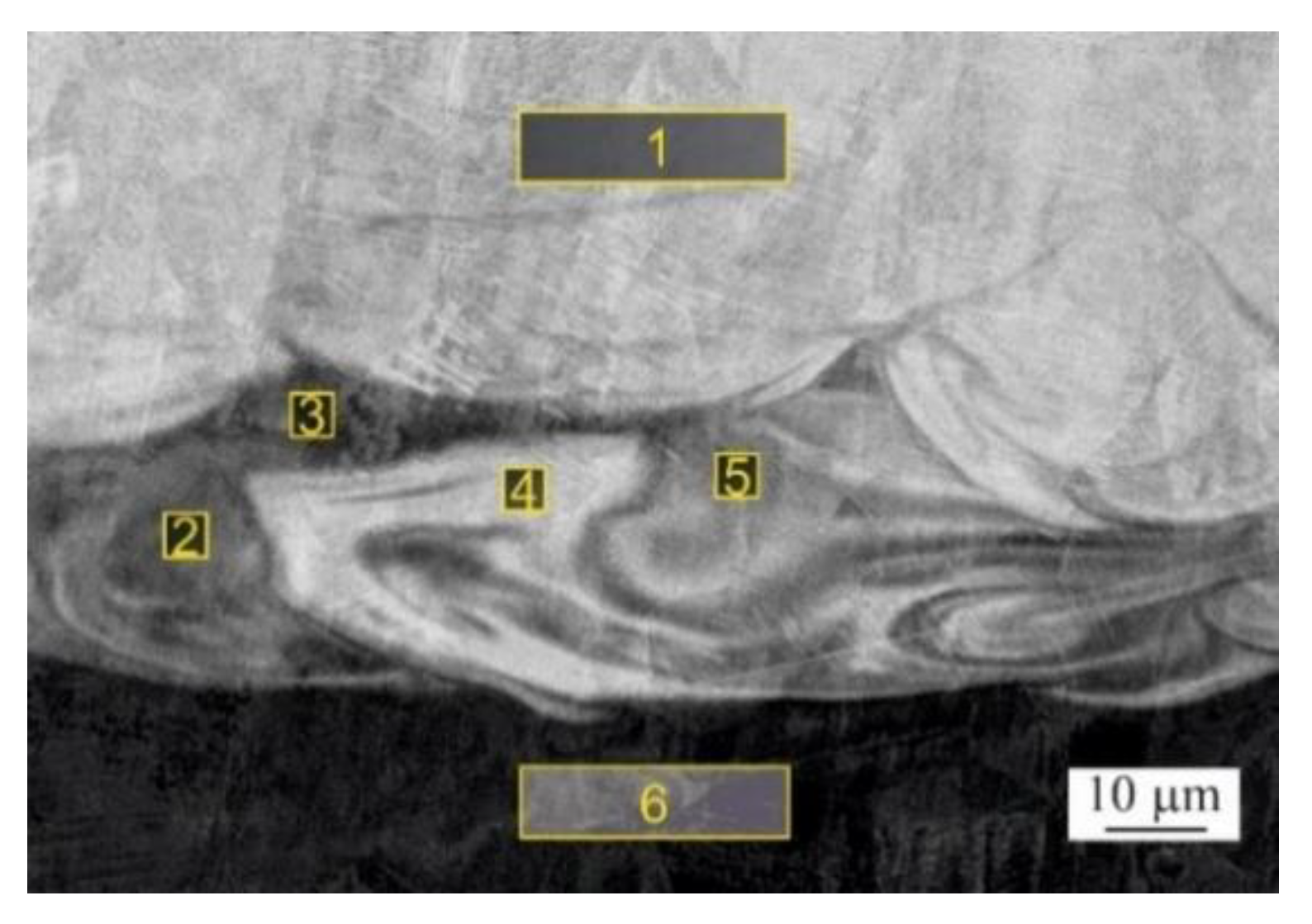
| Site No./Chemical Elements (wt.%) | Si | Cr | Mn | Fe | Co | Ni | Mo | W |
|---|---|---|---|---|---|---|---|---|
| Spectrum 1 | 0.97 | 24.42 | 0.95 | 2.93 | 55.72 | 0.00 | 6.70 | 8.31 |
| Spectrum 2 | 0.77 | 21.26 | 1.11 | 37.67 | 27.52 | 4.44 | 3.22 | 4.01 |
| Spectrum 3 | 0.71 | 20.58 | 1.26 | 43.55 | 22.68 | 5.18 | 2.59 | 3.45 |
| Spectrum 4 | 1.13 | 24.75 | 0.97 | 0.71 | 57.27 | 0.00 | 6.72 | 8.45 |
| Spectrum 5 | 0.85 | 21.78 | 1.18 | 30.75 | 33.04 | 4.06 | 3.67 | 4.67 |
| Spectrum 6 | 0.46 | 18.66 | 1.82 | 69.83 | 0.62 | 8.28 | 0.00 | 0.33 |
| Method | Substrate Material | Deposition Material | Laser Power [W] | Scanning Speed [mm/s] | Powder Thickness [mm] | Vickers Hardness [HV] * | Adhesion Strength [MPa] | Ref./Year |
|---|---|---|---|---|---|---|---|---|
| SLM | 304 SS | CoCr | 90 | 800 | 0.02 | 451–483 | 838 | This study |
| SLM | Cast iron | Inconel 625 | 200 | N/A | 0.06 | 330–400 | N/A | [5]/2018 |
| DED | H13 tool steel | CoCr | 350 | 3.7 | 0.60 | 520–650 | 618–624 | [3]/2019 |
| 304L SS | Inconel 625 | 910 | N/A | N/A | 210–250 | N/A | [47]/2016 | |
| 316L SS | Inconel 718 | 450–750 | 4.0 | 0.55–0.80 | 140–180 | 530–595 | [46]/2014 | |
| Carbon steel C40 | 316L SS | N/A | N/A | N/A | 220–510 | N/A | [9]/2019 | |
| 316L SS | 316L SS | 225 | 33.3 | 0.12 | 180–225 | 430 | [11]/2020 | |
| Cast iron | EuTroLoy 16006 (Co-based alloy) | 634–1671 | 2–6.67 | N/A | 490–600 | N/A | [18]/2007 |
Publisher’s Note: MDPI stays neutral with regard to jurisdictional claims in published maps and institutional affiliations. |
© 2022 by the authors. Licensee MDPI, Basel, Switzerland. This article is an open access article distributed under the terms and conditions of the Creative Commons Attribution (CC BY) license (https://creativecommons.org/licenses/by/4.0/).
Share and Cite
Cosma, C.; Teusan, C.; Gogola, P.; Simion, M.; Gabalcova, Z.; Trif, A.; Berce, P.; Balc, N. Investigation of the Interface between Laser-Melted CoCr and a Stainless Steel Substrate. Metals 2022, 12, 965. https://doi.org/10.3390/met12060965
Cosma C, Teusan C, Gogola P, Simion M, Gabalcova Z, Trif A, Berce P, Balc N. Investigation of the Interface between Laser-Melted CoCr and a Stainless Steel Substrate. Metals. 2022; 12(6):965. https://doi.org/10.3390/met12060965
Chicago/Turabian StyleCosma, Cosmin, Christina Teusan, Peter Gogola, Mihaela Simion, Zuzana Gabalcova, Adrian Trif, Petru Berce, and Nicolae Balc. 2022. "Investigation of the Interface between Laser-Melted CoCr and a Stainless Steel Substrate" Metals 12, no. 6: 965. https://doi.org/10.3390/met12060965
APA StyleCosma, C., Teusan, C., Gogola, P., Simion, M., Gabalcova, Z., Trif, A., Berce, P., & Balc, N. (2022). Investigation of the Interface between Laser-Melted CoCr and a Stainless Steel Substrate. Metals, 12(6), 965. https://doi.org/10.3390/met12060965