Article

VHCF Behavior of Inconel 718 in Different Heat Treatment Conditions in a Hot Air Environment

by
Sebastian Schöne
1,2,*,
Sebastian Schettler
1,
Martin Kuczyk
2,
Martin Zawischa
1 and
Martina Zimmermann
1,2
1
Fraunhofer Institute for Material and Beam Technology IWS, 01277 Dresden, Germany
2
Institute of Materials Science, Technische Universität Dresden, 01069 Dresden, Germany
*
Author to whom correspondence should be addressed.
Metals 2022, 12(7), 1062; https://doi.org/10.3390/met12071062
Submission received: 24 May 2022 / Revised: 16 June 2022 / Accepted: 20 June 2022 / Published: 21 June 2022

Abstract

:
The very high cycle properties of Inconel 718 in two different heat treatment conditions were investigated at a test temperature of 500 °C. One condition was optimized for fatigue strength and displayed a finer-grained microstructure, while the second batch had a more coarse-grained microstructure. For the high-temperature ultrasonic fatigue testing, a new test concept was developed. The method is based on the principle of a hot-air furnace and thus differs from the conventionally used induction heaters. The concept could be successfully evaluated in the course of the investigations. The materials’ microstructure was analyzed before and after fatigue testing by means of metallographic and electron backscatter diffraction (EBSD)analysis. The results show a significant influence of the heat treatment on the fatigue strength caused by the specific microstructure. Further, a difference in crack propagation behavior due to microstructural influences and non-metallic precipitations was observed.

1. Introduction

Moving parts in power plant turbines or aerospace applications are subject to very high numbers of load cycles over their operating lifetime. In addition to cyclic mechanical stress, also high thermal loads occur in such greatly stressed application areas. Therefore, high-temperature materials such as nickel-based superalloys are commonly used. However, the fatigue behavior of metallic materials at elevated temperatures fundamentally differs from the behavior at room temperature [1]. In order to ensure safe and reliable service, both the influence of cyclic and mechanical stress and the exposition to high temperatures have to be evaluated.
A frequently used and already fundamentally investigated high-temperature resistant material is Inconel 718. Several studies have already analyzed the fatigue behavior at room temperature, including ultrasonic fatigue investigations up to the very high cycle fatigue (VHCF) region. Particularly relevant for use in safety-relevant components, failure up to the range of 1 × 10⁸ cycles could be detected [2,3]. However, the focus of previous investigations was on fatigue behavior at elevated temperatures. Compared to room temperature, fatigue results showed deviating fatigue mechanisms such as an oxide-induced crack closure effect which resulted in increased fatigue life at 500 °C [4,5]. In addition, some results from ultrasonic fatigue testing show a continuous decrease in fatigue strength well into the VHCF range [4,6]. In most investigations, specimen material was conditioned by appropriate heat treatment strategies to achieve the highest possible fatigue strength. Therefore, the influence of a deviation from the established heat treatment condition of Inconel 718 on fatigue strength and fatigue mechanism has not yet been studied in detail. Studies on other nickel-based superalloys, however, demonstrated that the heat treatment condition could have a significant influence on the fatigue behavior at elevated temperatures, in particular in the VHCF regime. Differences in fatigue behavior based on the interaction between dislocations and precipitations were found [1,7,8].
As shown by previous work, the use of special ultrasonic fatigue test equipment is appropriate to investigate the material behavior in the VHCF range. Further, numerous concepts have been developed to investigate the VHCF fatigue behavior of materials at elevated temperatures, mainly based on ultrasonic fatigue systems combined with induction furnaces. Even though this method allows high test temperatures, the setup is very intricate. Considerable effort is required to exclude the possible influences of the electromagnetic field on measurement and test technology. For example, the use of non-contact measuring devices that are insensitive to electromagnetic fields, such as pyrometers or fiber optic sensors for displacement measurement, becomes necessary [9,10,11,12,13]. The present study shows a new test concept for ultrasonic fatigue testing at temperatures of at least 500 °C. The concept is based on the principle of a hot-air furnace and thus differs from the typically used induction heaters.
This test setup was used to conduct high-temperature fatigue tests on age-hardenable nickel-based superalloy Inconel 718. The fatigue strength of Inconel 718 in two different heat treatment conditions was compared at a test temperature of 500 °C and up to 5 × 10⁹ cycles. The investigations aimed to study fatigue mechanisms at elevated temperatures as a function of the heat treatment condition and thus the microstructure. Therefore, one batch was analyzed and tested in a heat treatment condition that causes a very coarse-grained microstructure and, therefore, a good impact strength. A second batch was heat-treated in a way that the δ-phase precipitations were preserved together with a finer grain. Based on the significant difference in morphology and grain structure, deviation of fatigue strength is expected. This study aims to investigate differences in fatigue mechanisms caused by different microstructures under the influence of a hot air environment.

2. Materials and Methods

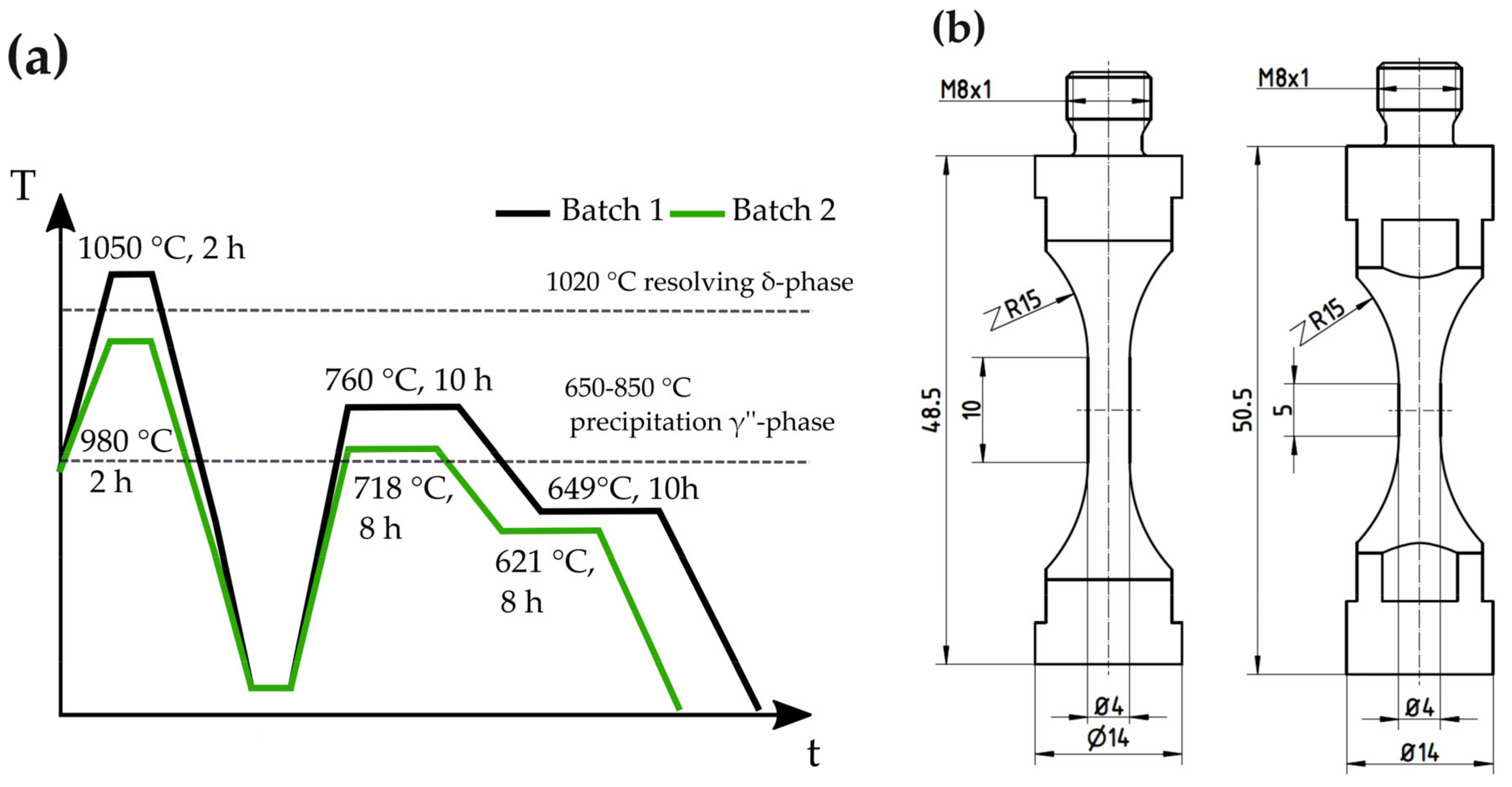
2.1. Material, Specimen Preparation, and Microstructural Characterisation Methods

The present study was performed on Inconel 718 with a chemical composition that is given in mass% in Table 1. Inconel 718 is an age-hardenable nickel-based superalloy, where the strengthening effect relates to the precipitation of the secondary γ’’-phase in the γ metal matrix. In addition, typical intermetallic phases are formed. The material was investigated in two different age-hardened heat treatment conditions, which differ in solution temperature as well as aging temperature and time. Details are shown in Figure 1a. Due to the lower solution temperature of batch 2, the primary δ-phase (Ni3Nb) remains at the grain boundaries. This leads to a significantly finer-grained microstructure after the following two-stage precipitation-hardening process. As a result, notch sensitivity and fatigue strength improve compared to the heat treatment of batch 1. Due to the coarse grain structure, batch 1 shows a high transverse ductility and impact strength. In addition to the different potential applications based on the heat treatment used, the significant difference in the resulting microstructure provides a basis to investigate fatigue mechanisms in Inconel 718 [14].
Fatigue specimens were machined from 16 mm bars into hourglass-shaped ultrasonic fatigue specimens with cylindrical gauge lengths of 4 mm in diameter. The gauge length of batch 1 was 10 mm (test volume 126 mm2), while the gauge length of batch 2 was limited to 5 mm (test volume 63 mm2) to enable ultrasonic fatigue tests at higher stress amplitudes. Both specimen geometries are displayed in Figure 1b. The influence of the different test volumes on the fatigue test results is negligible since the statistical distribution of crack-inducing defects is ensured in both test volumes. After heat treatment, the specimens were mechanically ground and polished to eliminate the influence of surface roughness. Metallographic cross-sections of both batches were prepared for microstructural and electron backscatter diffraction (EBSD) examination. For EBSD and EDX analysis, a scanning electron microscope of the type JSM-IT700HR (JEOL Ltd., Tokyo, Japan) in combination with a Symmetry S2 EBSD detector and an Ultim Max EDX detector (Oxford Instruments plc, Abingdon, UK) was used.

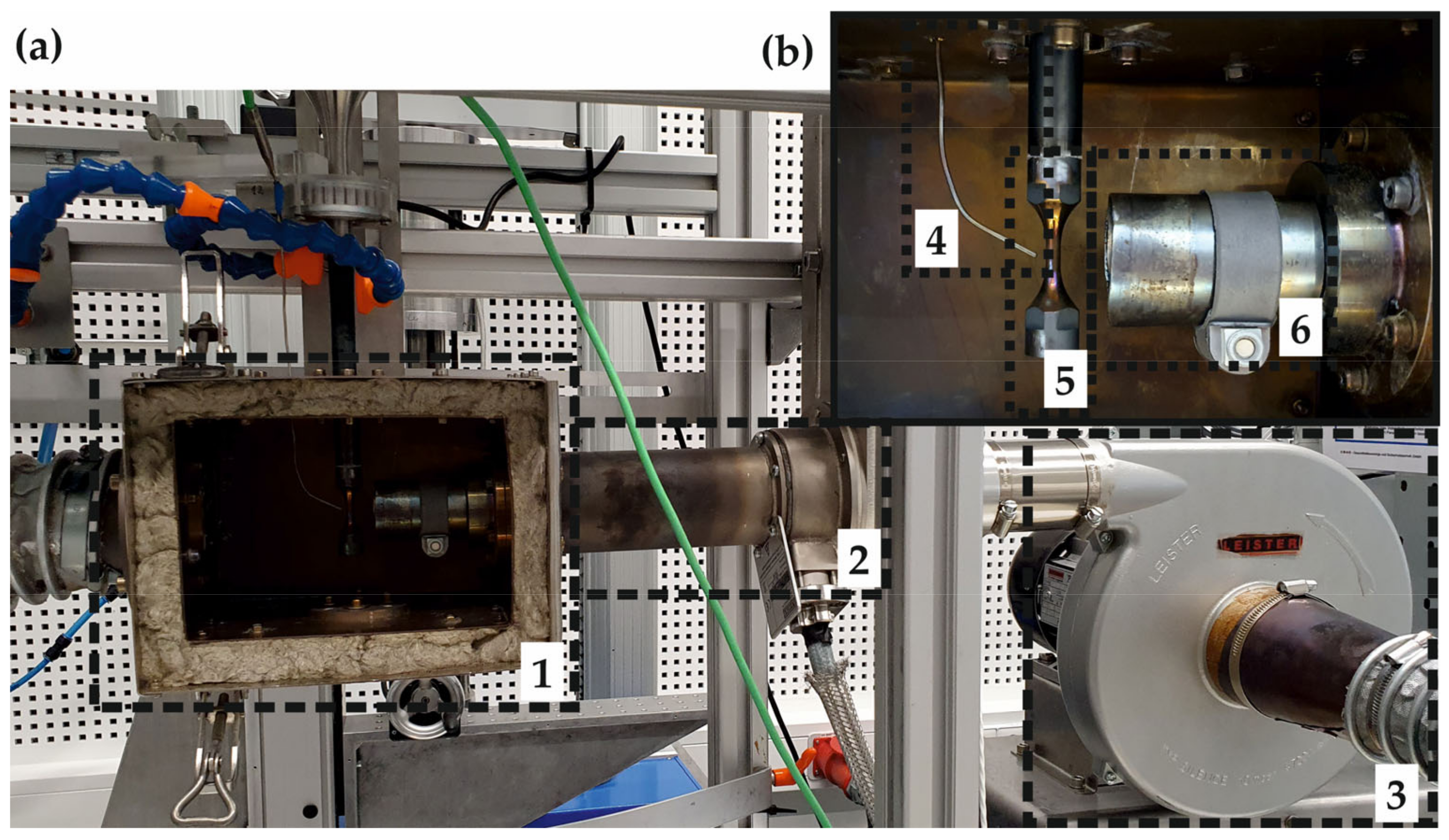
2.2. Fatigue Testing in Hot Air Environment

Fatigue tests were performed on an ultrasonic fatigue test stand (University of Natural Resources and Life Sciences, Vienna, Austria) at a stress ratio of R = −1 in laboratory air at a test temperature of 500 °C. In order to enable ultrasonic fatigue testing at elevated temperatures, a novel heating system was developed (Figure 2).
The concept is based on specimen heating with hot air, where a hot air stream is generated by a heating element supplied by a blower. In contrast to induction heating, the sample is not heated intrinsically but by convection. This distinction opens up the possibility of investigating various materials, even non-electrically conductive. Additionally, tests in a hot-air environment close to the application scenario are possible. In general, the concept enables fatigue testing at high temperatures without complex measurement technology. In contrast to systems based on inductive heating with resulting strong electromagnetic fields, for example, the use of inductive displacement sensors is possible. In the developed device, the specimen and the lower end of the load string are located in an insulated heating chamber. In order to optimize the energy utilization, the hot airstream is focused only on the specimen’s gauge length and gets recycled through a closed circulation system. In order to prevent overheating of the whole testing system, the load string was cooled using compressed air.
Specimen temperature is measured contactless by a thermocouple mounted behind and in the slipstream of the specimen. Temperature calibration is performed using a specimen with a central hole that allows measurement of the real core temperature due to a thermocouple. Due to the small specimen diameter in the measuring range, sufficiently uniform heating for practical applications can be achieved despite the one-sided heat input. Temperature regulation is carried out by a PID controller (Wachendorff Prozesstechnik GmbH & Co. KG, Geisenheim, Germany) through a thyristor power actuator (Thermokon Sensortechnik GmbH, Mittenaar, Germany). In order to limit uncontrolled self-heating of the specimens during the high-frequency fatigue test, experiments were performed in pulse–pause mode. Pulse and pause were individually adapted to each load amplitude. For high load amplitudes, pulse–pause ratios of 150 ms pulse time and 2000 ms pause time were used. For low load amplitudes, ratios of 200 ms pulse and 250 ms pause were used without any significant temperature rise detectable by a change in resonant frequency. Short pulse and long pause times reduce the effective test frequency at high-stress amplitudes, whereas the ratio selected for the low-stress amplitudes allows a short test for the VHCF range. In this paper, we report on the very high cycle fatigue properties of Inconel 718 in two different heat treatment conditions at a test temperature of 500 °C. In addition, the adjacent airflow dissipates the intrinsically generated heat, as in a compressed air cooling system.

2.3. Young’s Modulus Determination

To determine reliable strength parameters with an ultrasonic fatigue system, precise knowledge of Young’s modulus is crucial. Since materials’ Young’s modulus decreases with increasing test temperature, the resonance length of ultrasonic fatigue specimen will be shorter and the resonance frequency lower than that at ambient temperature.
Therefore, it is essential to determine Young’s modulus at the test temperature. For this purpose, the fatigue specimens were investigated by laser-induced surface acoustic wave spectroscopy using a “LAwave” measurement system (Fraunhofer IWS, Dresden, Germany) [15]. This method allows the non-destructive and very precise determination of the elastic properties directly in the test area of the specimens, even at elevated temperatures. Typically, this method is used to characterize coatings [16] and effects due to other surface treatments such as machining [17] or hardening [18], but the measurement of Young’s modulus within the upper 1–1.5 mm of a homogeneous material surface is also possible. The measuring principle is based on the measurement of the propagation velocity of surface acoustic waves, which depends on the elastic properties and density of a material. The waves were generated by a short laser pulse on the specimen surface, and their running time was measured by a piezoelectric transducer in distance of about 8 mm. To determine Young’s modulus, density values of 8.26 g/cm3 at room temperature, 8.20 g/cm3 at 200 °C, and 8.09 g/cm3 at 500 °C were used. Furthermore, a Poisson’s ratio of 0.29 was assumed.

3. Results

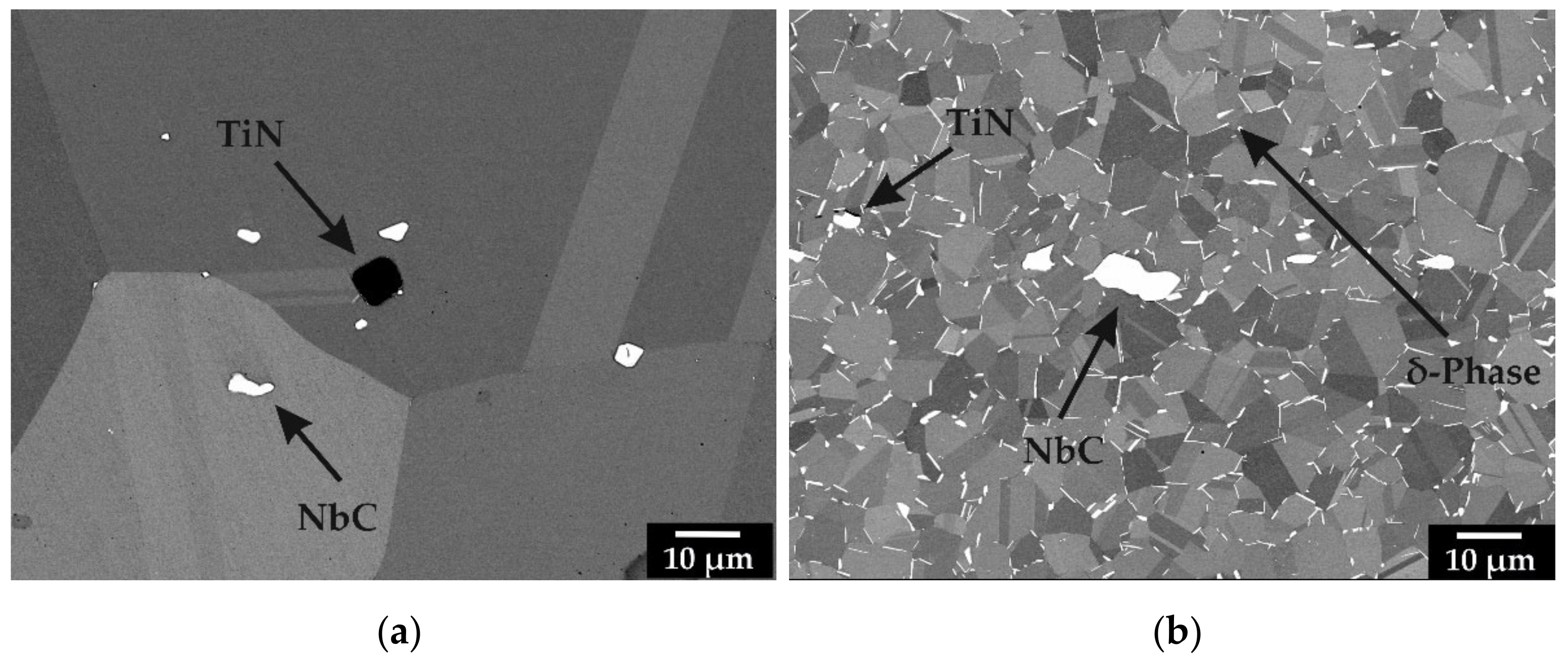
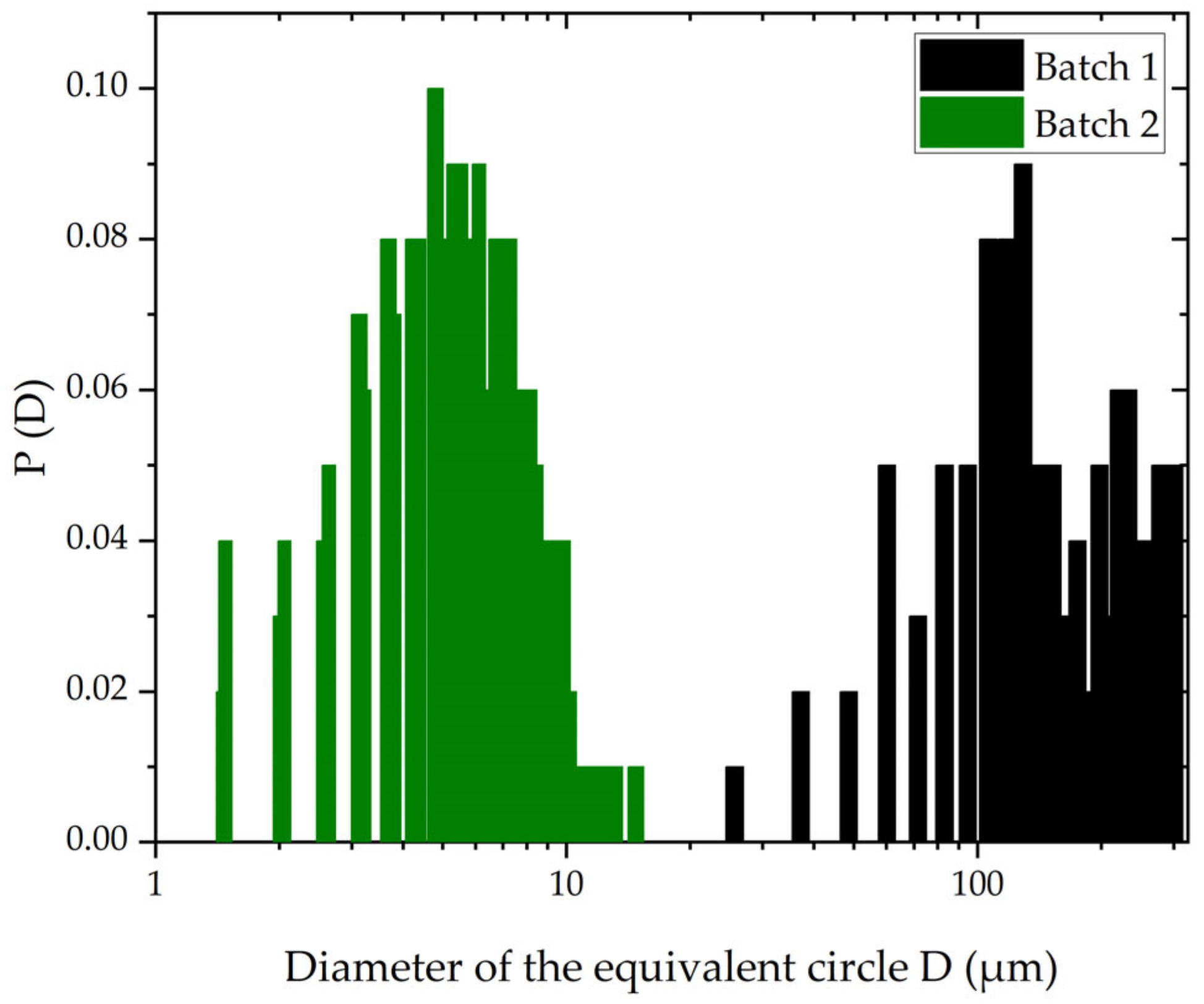
3.1. Microstructural and Mechanical Analysis

The microstructures of the conditions investigated are shown in Figure 3. In addition to the clear difference in grain size (Figure 4), non-metallic inclusions in the form of TiN and NbC can be found through EDX and EBSD analysis. TiN precipitates are characterized by their angular shape, while NbC precipitates assume an irregular, smaller shape. Fine lenticular particles of the δ-phase can only be observed along the grain boundaries in the microstructure of batch two.
In order to investigate the influences of the microstructural differences found on mechanical parameters, measurements of hardness and Young’s modulus were conducted. In order to take into account the significant difference in grain size of both batches, microhardness (HV0.3) and macrohardness measurements (HV 10) were performed comparatively. As shown by the results in Table 2, in conjunction with the standard deviation σ, there is no significant difference in hardness between the two batches. The Young’s modulus was determined in the range of room temperature up to the test temperature of 500 °C using the surface acoustic wave spectroscopy. The obtained data were extrapolated using linear polynomial fitting for the whole measurement range. As with the hardness measurement, no significant deviation can be found in Young’s modulus between the two batches. The difference found can be attributed mainly to fluctuations in the microstructure, which have a greater influence on the measurement results for the significantly coarser-grained batch one than for batch two. This is also evident from the higher deviation of the measured values by surface acoustic wave spectroscopy. Greater confidence in Young’s modulus determined is possible with a high number of measurements. Nevertheless, a significantly increased attenuation behavior of batch one could be observed during the measurements.

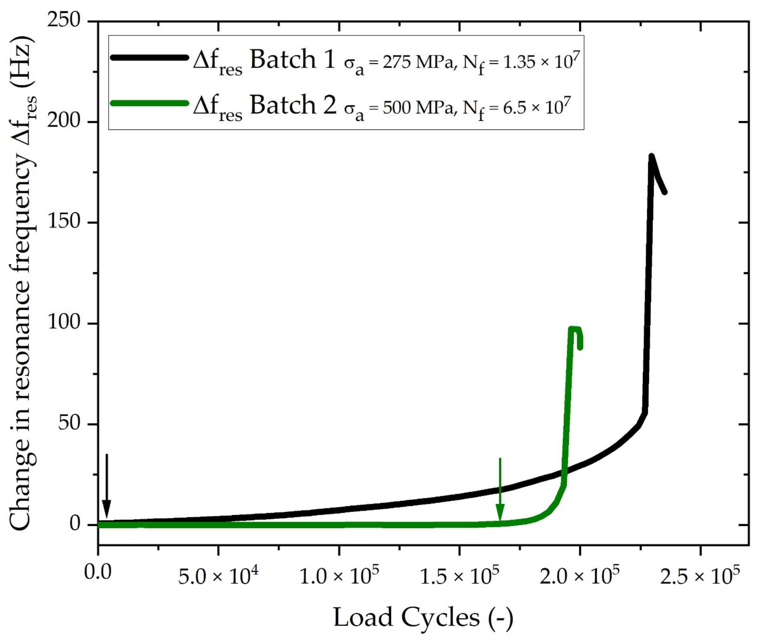
3.2. High-Temperature Fatigue Behavior in the VHCF Regime

Figure 5 shows the S-N plot for both batches of Inconel 718 obtained at 500 °C by ultrasonic fatigue testing under a load ratio of R = −1. Batch two shows significantly higher fatigue strength compared to batch one above 105 cycles. In the range below 105 cycles, the difference in fatigue strength does not turn out so obviously. While a significant decrease in fatigue strength due to high temperature is obvious for batch one, batch two reaches values comparable to fatigue results of Inconel 718 at room temperature [2,6]. Both batches show failure even beyond 106 cycles, while no failures can be observed beyond 108 cycles. All tested stress amplitudes are well below the typical 0.2% proof stress of about 1000 MPa and, therefore, in the range of fully elastic deformation, which can be reliably tested by ultrasonic fatigue technology [5].
Following fatigue tests, fractographic analyses were performed using scanning electron microscopy. In Figure 6, the significant differences in fracture surfaces between the investigated batches become obvious. In Figure 6b, a typical smooth fatigue fracture surface of batch two with concentric beach lines is shown. Fracture surfaces of batch one, on the other hand, are characterized by fissured surfaces with marks of intercrystalline cracking. In all examined specimens, the crack origin is located in areas next to the sample surface. However, no precise microstructural feature could be identified as a crack-initiation origin for batch two. Here, locations of increased plastic deformation such as grain or twin boundaries can have a crack-inducing effect. On the fracture surfaces of batch one, TiN particles could be observed in the dark area of the crack initiation point. These observations are consistent with results from previous studies [2,3].

3.3. Crack Growth Behavior

Based on the results of fatigue tests and fractographic analyses, a microstructural influence on crack growth can be assumed. It has already been shown repeatedly that the crack growth phase takes up only a small part of the total life of materials in the VHCF range and that this is largely determined by crack initiation. Nevertheless, conclusions on mechanisms of very early crack growth can be drawn from findings on crack growth behavior, and important effects in fatigue behavior at elevated temperatures can be identified. To analyze this, in addition to the fracture surface analyses, the resonance frequency during fatigue testing was investigated. The resonance frequency is very sensitive to fatigue crack growth and is therefore widely used for damage detection in ultrasonic fatigue testing technology [3]. The fatigue crack growth causes a decreasing stiffness of the specimen in the test area and thus a significant decrease in the resonance frequency. Figure 7 shows that the crack growth phase in the coarse-grained batch one is about ten times longer than in the finer-grained batch two. This behavior is exhibited by all specimens with a relevant high fracture load cycle number.
Due to the differences in fracture surfaces and crack growth rate, additional EBSD investigations were carried out in the area around the crack to identify any differences in the crack growth mechanisms. Therefore, metallographic sections of the test area were prepared parallel to the specimen axis. Figure 8 shows exemplary crack paths of the investigated batches starting at the surface inside the gauge length. The fine microstructure of batch two leads to a much straighter crack path and thus to a smoother fracture surface shown in Figure 6. Furthermore, EBSD data show that, especially in batch one, the crack runs both at the grain boundaries and through the grains. Upon further investigation, it becomes clear that grains with a low Schmid factor are preferably bypassed via the grain boundaries, while grains with a higher Schmid factor are cut by the crack (Figure 9). In some cases, directional changes of 90° can be observed within such grains. In the coarse microstructure of batch one, the crack is hindered by the found precipitations. In the fine structure of batch two, these phenomena could not be observed in detail. Here, mainly transcrystalline crack growth is present.

4. Discussion

In order to investigate the effect of two heat treatments on the fatigue behavior of Inconel 718 in a hot air environment, microstructural analysis, as well as ultrasonic fatigue tests at 500 °C and up to 5 × 10⁹ cycles, were performed. The results show significant differences in the microstructure and thus an influence on fatigue mechanism and consequently on the fatigue strength.
Differences in the heat treatments affect the microstructure mainly by grain size and content of δ-phase precipitations but do not significantly impact the hardness or Young’s modulus. The absence of difference in the measured hardness is remarkable since the different grain boundary densities, as well as the finely dispersed δ-phase precipitates, should imply a higher hardness in batch two by precipitation hardening effects. The influence of the finely dispersed γ″-phase in the metal matrix apparently outweighed the influences of the investigated precipitations and grain boundaries on this quasi-static behavior.
Since the material was subjected to a temperature of 500 °C during the fatigue test, temperature-induced microstructural changes are of particular interest. Neither in samples with long nor with short test times could such changes be detected based on the investigations carried out. At test temperature below 0.4 times the melting temperature of around 1300 °C and at the mainly short testing time of ultrasonic fatigue testing, changes based on recrystallization and dislocation movement were not to be expected. Nevertheless, the combination of elevated temperature and high-cycle plastic deformation can lead to phase transformations, especially at long-term test times in the VHCF regime. In the investigated range of high to very high cycle fatigue, plastic deformations do not occur globally. Typically, areas around brittle precipitates in a ductile matrix are critical points of local plastic deformation. Under such conditions, the transformation of the γ″- phase into δ-phase particles was observed by Jambor et al. [19]. Due to their location in the grain interior, these precipitates significantly reduce the fatigue strength, especially in the coarse-grained microstructure, compared to δ-phase particles in the range of the grain boundaries of batch two. Since the research program in this project did not foresee any detailed analyses of the γ″-precipitates evolution during elevated temperature VHCF tests, likely influences are still an open question.
As in the formation of the microstructure, the investigated batches also differ in fatigue strength. The fatigue results obtained at 500 °C for both heat treatment conditions show a typical one-step progression of S-N curves and therefore suggest a true fatigue strength. Contrary to the results obtained here, previous studies on Inconel 718 have assumed a constant decrease in fatigue strength at elevated temperatures. Batch two achieves the expected strength values in the range of literature data at room temperature. Batch one, on the other hand, shows significantly lower values. Such differences are mainly attributable to the different grain boundary densities and the presence of non-metallic inclusions to a considerable extent. Due to their brittleness and stress concentration, the non-metallic inclusions are potential initiation sites for fatigue cracks, both on the specimen surface and inside the material. Grain boundaries, on the other hand, inhibit crack growth due to their barrier effect.
Nevertheless, since fatigue life in the VHCF range is dominated by crack initiation and very early crack growth, the behavior of fatigue cracks as well as temperature-induced interaction of micro-cracks with the environment must be considered to explain the fatigue behavior of Inconel 718 at elevated temperature. As described above, the reason for the significantly different fatigue strength of the two batches is the optimized heat treatment and the resulting microstructure. The lower fatigue strength of batch one can be explained not only by the lower grain boundary density but also by the location of these precipitates. As can be seen, by SEM and EBSD examinations, an increased number of precipitates is located in the interior of the grains. Compared to precipitations in the area of the grain boundaries, these have a more critical effect as crack initiation sites and can lead to the formation of critical crack lengths at lower stress amplitudes.
In contrast to the crack initiation site’s effect, precipitations are also able to slow down or even stop early crack propagation by obstacle effect, as well as grain boundaries can do [20]. These effects, which counteract crack growth, are particularly noticeable in the case of batch two. This is reflected by the significantly increased fatigue strength. Thus, the formation of isolated slip bands responsible for crack initiation due to increased activity of dislocations at elevated temperatures are hindered or maybe even suppressed. As a result, fatigue strength values in the range of the results at room temperature can be achieved in batch two. The unchanged fatigue strength of nickel-based alloys at temperatures in the range of 400–600 °C can be explained by a more pronounced homogeneous dislocation motion based on the specific interaction between dislocations and particles. In investigations on Nimonic 80A, strength-reducing processes were only observed above 800 °C [1]. Extensive studies on the influence of precipitates and their interaction with dislocations in the fatigue of nickel-base alloys have been carried out by Stöcker et al. [7,8].
Since the difference in fatigue strength depicted in Figure 5 is very pronounced, not only differences in crack initiation but also the influence of early crack growth shall be considered. This is also supported by the difference in crack growth between the two batches, as shown in Figure 6, and the findings from fractographic and EBSD analysis. The fracture surfaces found indicate a long crack initiation phase following a fast crack growth. For the more fissured fracture surface of batch one, intercrystalline crack growth is evident, while the fracture surface of batch two shows a smoother surface due to the smaller grain size. EBSD data show that the crack in the coarse microstructure of batch one grows preferentially through grains with high Schmid factor, whereas grains with low Schmid factor are bypassed. Grain boundaries, twins, and precipitations form obstacles, hinder crack growth and lead to a longer crack growth phase. This effect has been proven for EN-AW 6082, where microstructural features such as large precipitates and grain boundaries had a significant effect on the crack propagation at growth rates close to the threshold region [20]. In the finer microstructure of batch two, mainly transcrystalline crack growth was observed. Due to the high grain boundary density and the additionally intercalated delta precipitates, early crack growth is thus more strongly suppressed than in batch one. This is a likely explanation for the increased fatigue strength and the shorter crack growth phase. Furthermore, in the coarser-grained microstructure of batch one, crack initiation at precipitates inside the grain can lead to a critical crack length being exceeded unhindered already within one grain. Additionally, a high damping behavior of batch one became evident during Young’s modulus measurement using surface acoustic wave spectroscopy, which is due to the significantly coarser-grained microstructure. A high damping capacity may indicate an increased energy absorption capacity that significantly slows crack growth, which in turn leads to the long crack growth phase. However, this cannot be proven with certainty since grain-size-dependent effects, such as scattering at the grain boundaries, can also cause increased damping.
If the load amplitudes are small enough and a fatigue crack propagates at growth rates close to the threshold region, the crack is stopped in the early stage. If the applied loads exceed a threshold, the crack quickly grows to a critical size under an additional effect of matrix softening. This circumstance explains the absence of fractures at load cycles above 6 × 10⁷ cycles, even though fatigue tests were performed up to 5 × 10⁹ cycles. The interaction of all effects is particularly evident in batch two at a stress level of 538 MPa. Here, fractures occurred at about 2 × 10⁵, 7 × 10⁷, as well as two runouts at about 4 × 10⁹ [4,6]
In addition to crack initiation and early crack growth, the interaction between the microcrack and the environment plays a decisive role in high-temperature fatigue. Such temperature-induced interactions of microcracks with the environment are oxide-induced crack closure effects. In some cases, crack closure effects in Inconel 718 lead to higher fatigue strength at 500 °C compared to room temperature. Kawagoishi et al. [5] observed that cracks can grow to a length of 20–30 µm at the surface before they start non-propagating. In the work of Yan et al. [4], significantly higher strength values at 500 °C were achieved at a test frequency of 55 Hz than in the tests carried out in this work. This suggests that at test frequencies of 20 kHz, the oxide-induced crack closure effect no longer has a crucial impact. The duration of crack opening and the time period of crack growth in the oxidizing environment is too short at a test frequency of 20 kHz to allow a significant oxide layer to grow. Rather, already discussed microstructural influences may be a reason for a significant reduction in crack propagation at very low amplitudes and high frequencies. Nevertheless, once the early crack growth has been stopped temporarily by microstructural obstacles, the oxide-induced crack closure effect can lead to the permanent end of crack growth at constant amplitude due to the high ambient temperature.

5. Conclusions

In this study, fatigue tests on Inconel 718 were performed at 500 °C in the VHCF regime under fully reverse loading up to 5 × 10⁹ cycles. In the course of this study, a new test concept for ultrasonic fatigue testing up to 500 °C was designed. It is based on the principle of a hot-air furnace and thus stands out from the induction heating commonly used. In the context of the investigations, the influence of two heat treatments on the fatigue strength at elevated operating temperatures was investigated. The two batches differed significantly in their grain size caused by the remaining δ-precipitations in one batch. The most important conclusions obtained are summarized as follows:
  • The developed testing concept allows reliable ultrasonic fatigue testing up to at least 500 °C and 5 × 10⁹ cycles. At the same time, it requires less technical effort and is more economical than previous developments.
  • The Young’s modulus could be determined up to the test temperature of 500 °C by laser-induced surface acoustic wave spectroscopy using an “LAwave” measurement system
  • The differences in the microstructure of the two batches are not reflected in the hardness and Young’s modulus.
  • The fatigue test results show a significant difference in cyclic life caused by different heat treatments. The finer-grained microstructure permits fatigue strength in the range of results at room temperature and significantly exceeds the values of the more coarse-grained batch.
  • In both batches, no fractures at load cycles above 6 × 10⁷ cycles were found. This is attributed to the suppression of early crack growth at growth rates near the threshold region by microstructural obstacles. Whether oxide-induced crack closure effects also contributed to the lack of failure beyond 6 × 10⁷ cycles cannot be fully ruled out.
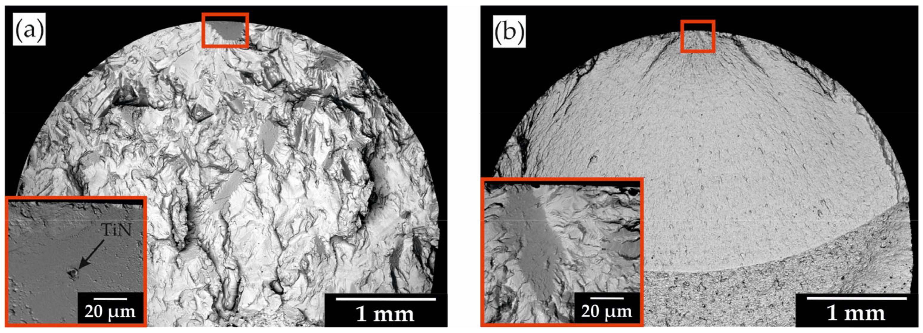
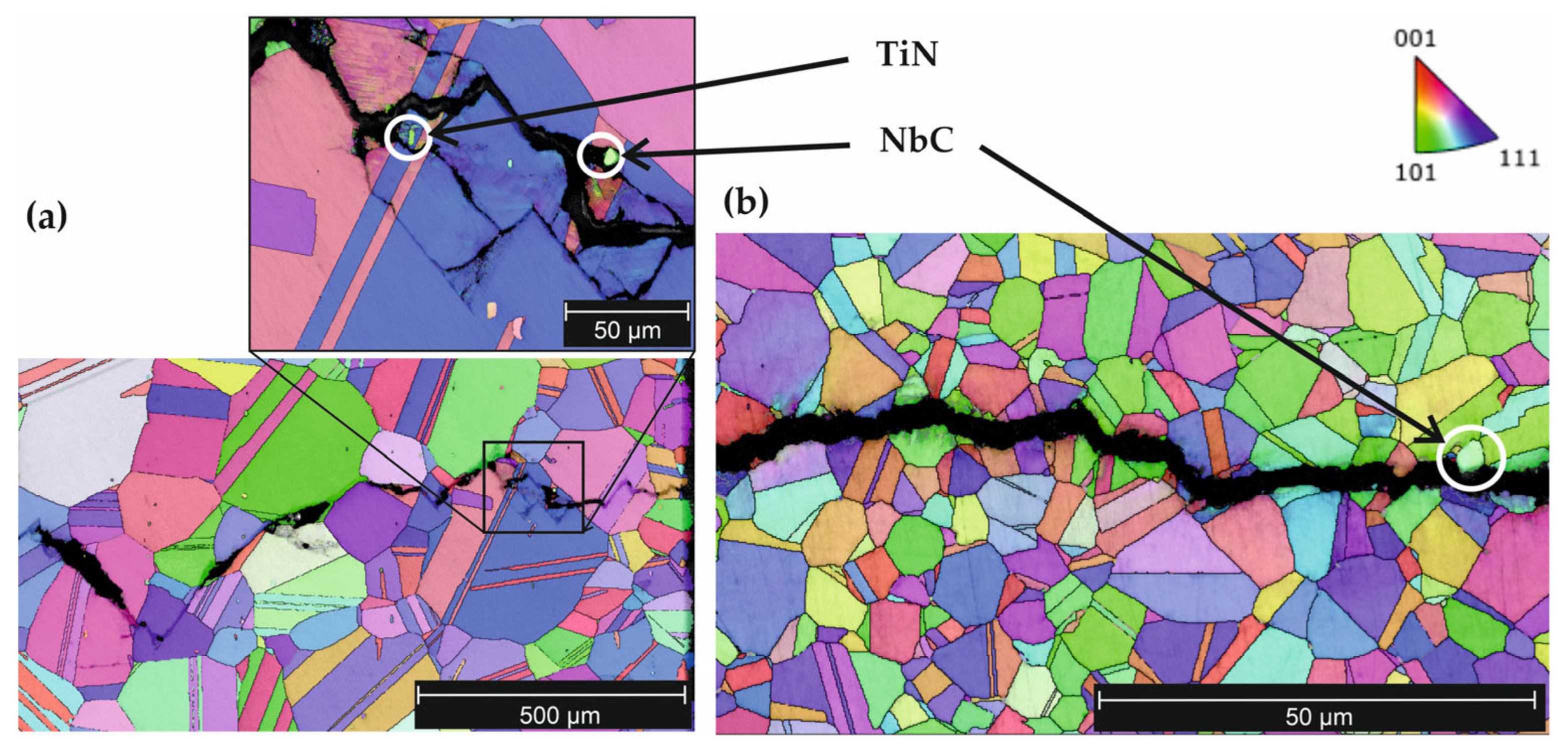
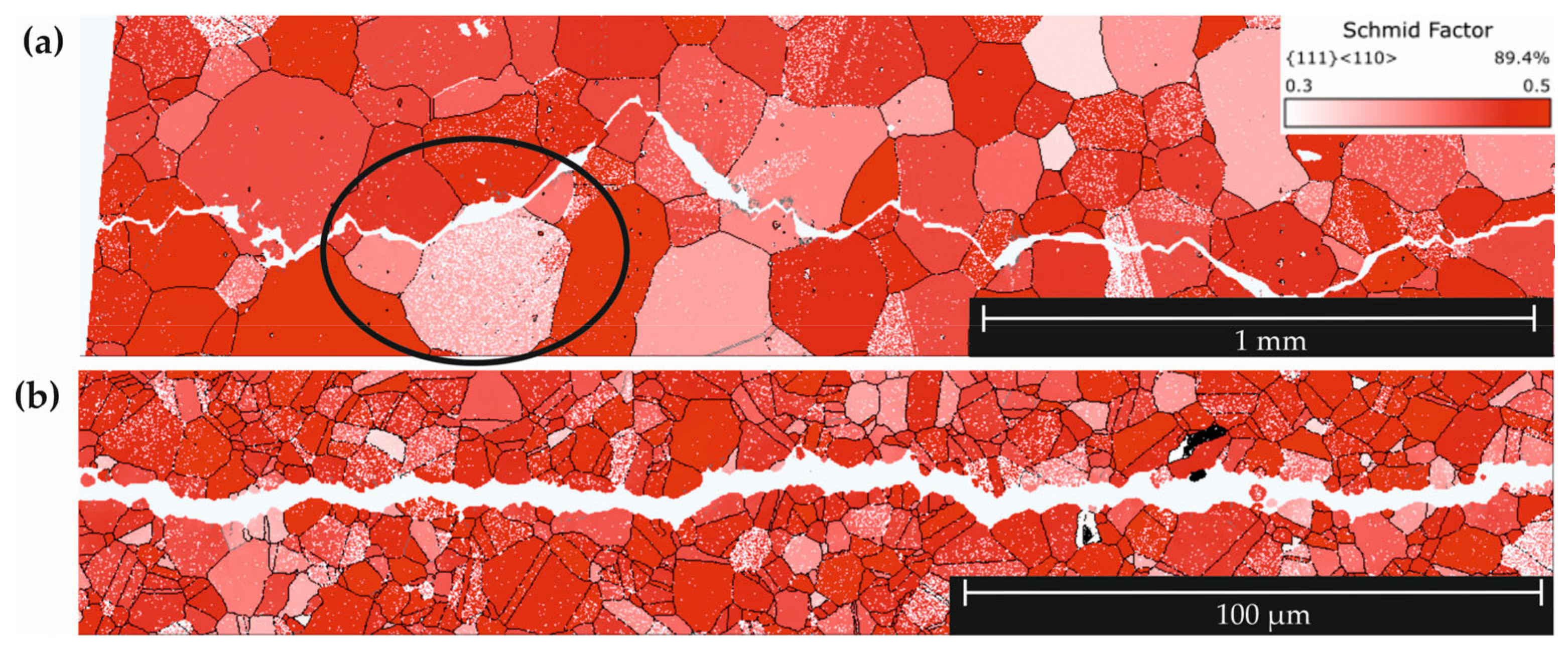
  • Fractographic investigations and EBSD analysis show differences in crack propagation, which also result in different periods of fatigue crack propagation. By means of EBSD investigations, it was observed that the fatigue cracks grew along the boundaries of grains with low Schmid factor, while grains with high Schmid factor were more likely to pass through. In addition, the crack deflection was observed at non-metallic inclusions.
Based on the successfully applied methodology, further ultrasonic fatigue investigations in the VHCF area should mainly focus on the influence of microstructure development, γ’″-precipitation, and oxide-induced crack closure effects.

Author Contributions

Conceptualization, S.S. (Sebastian Schettler) and M.Z. (Martina Zimmermann); methodology, S.S. (Sebastian Schöne), S.S. (Sebastian Schettler), M.K. and M.Z. (Martin Zawischa); validation, S.S. (Sebastian Schöne), S.S. (Sebastian Schettler) and M.Z. (Martina Zimmermann); formal analysis, S.S. (Sebastian Schöne); investigation, S.S. (Sebastian Schöne), M.K. and M.Z. (Martin Zawischa); resources, S.S. (Sebastian Schettler) and M.Z. (Martina Zimmermann); writing—original draft preparation, S.S. (Sebastian Schöne); writing—review and editing, M.Z. (Martina Zimmermann), S.S. (Sebastian Schöne); visualization, S.S. (Sebastian Schöne); supervision, S.S. (Sebastian Schettler) and M.Z. (Martina Zimmermann); project administration, S.S. (Sebastian Schöne) and S.S. (Sebastian Schettler). All authors have read and agreed to the published version of the manuscript.

Funding

This research received no external funding.

Institutional Review Board Statement

Not applicable.

Informed Consent Statement

Not applicable.

Data Availability Statement

The data presented in this study are available on request from the corresponding author.

Conflicts of Interest

The authors declare no conflict of interest.

References

  1. Zimmermann, M.; Stöcker, C.; Christ, H.-J. On the effects of particle strengthening and temperature on the VHCF behavior at high frequency. Int. J. Fatigue 2011, 33, 42–48. [Google Scholar] [CrossRef]
  2. Ma, X.; Duan, Z.; Shi, H.; Murai, R.; Yanagisawa, E. Fatigue and fracture behavior of nickel-based superalloy Inconel 718 up to the very high cycle regime. J. Zhejiang Univ. Sci. A 2010, 11, 727–737. [Google Scholar] [CrossRef]
  3. Chen, Q.; Kawagoishi, N.; Wang, Q.; Yan, N.; Ono, T.; Hashiguchi, G. Small crack behavior and fracture of nickel-based superalloy under ultrasonic fatigue. Int. J. Fatigue 2005, 27, 1227–1232. [Google Scholar] [CrossRef]
  4. Yan, N.; Kawagoishi, N.; Chen, Q.; Wang, Q.Y.; Nisitani, H. Fatigue Properties of Inconel 718 in Long Life Region at Elevated Temperature. KEM 2003, 243, 321–326. [Google Scholar] [CrossRef]
  5. Kawagoishi, N.; Chen, Q.; Nisitani, H. Fatigue strength of Inconel 718 at elevated temperatures. Fatigue Fract. Eng. Mater. Struct. 2000, 23, 209–216. [Google Scholar] [CrossRef]
  6. Amanov, A.; Pyun, Y.-S.; Kim, J.-H.; Suh, C.-M.; Cho, I.-S.; Kim, H.-D.; Wang, Q.; Khan, M.K. Ultrasonic fatigue performance of high temperature structural material Inconel 718 alloys at high temperature after UNSM treatment. Fatigue Fract. Eng. Mater. Struct. 2015, 38, 1266–1273. [Google Scholar] [CrossRef]
  7. Stöcker, C.; Zimmermann, M.; Christ, H.-J. Localized cyclic deformation and corresponding dislocation arrangements of polycrystalline Ni-base superalloys and pure Nickel in the VHCF regime. Int. J. Fatigue 2011, 33, 2–9. [Google Scholar] [CrossRef]
  8. Stöcker, C.; Zimmermann, M.; Christ, H.-J. Effect of precipitation condition, prestrain and temperature on the fatigue behaviour of wrought nickel-based superalloys in the VHCF range. Acta Mater. 2011, 59, 5288–5304. [Google Scholar] [CrossRef]
  9. Wagner, D.; Cavalieri, F.J.; Bathias, C.; Ranc, N. Ultrasonic fatigue tests at high temperature on an austenitic steel. Propuls. Power Res. 2012, 1, 29–35. [Google Scholar] [CrossRef]
  10. Smaga, M.; Boemke, A.; Daniel, T.; Skorupski, R.; Sorich, A.; Beck, T. Fatigue Behavior of Metastable Austenitic Stainless Steels in LCF, HCF and VHCF Regimes at Ambient and Elevated Temperatures. Metals 2019, 9, 704. [Google Scholar] [CrossRef] [Green Version]
  11. Furuya, Y.; Kobayashi, K.; Hayakawa, M.; Sakamoto, M.; Koizumi, Y.; Harada, H. High-temperature ultrasonic fatigue testing of single-crystal superalloys. Mater. Lett. 2012, 69, 1–3. [Google Scholar] [CrossRef]
  12. Schmiedel, A.; Henkel, S.; Kirste, T.; Morgenstern, R.; Weidner, A.; Biermann, H. Ultrasonic fatigue testing of cast steel G42CrMo4 at elevated temperatures. Fatigue Fract. Eng. Mater. Struct. 2020, 43, 2455–2475. [Google Scholar] [CrossRef]
  13. Smalcerz, A.; Przylucki, R. Impact of Electromagnetic Field upon Temperature Measurement of Induction Heated Charges. Int. J. Thermophys. 2013, 34, 667–679. [Google Scholar] [CrossRef] [Green Version]
  14. Oradei-Basile, A.; Radavich, J.F. A Current T-T-T Diagram for Wrought Alloy 718. Superalloys 1991, 718, 325–335. [Google Scholar]
  15. Schneider, D.; Schwarz, T. A photoacoustic method for characterising thin films. Surf. Coat 1997, 91, 136–146. [Google Scholar] [CrossRef]
  16. Schneider, D.; Schultrich, B.; Scheibe, H.J.; Ziegele, H.; Griepentrog, M. A laser-acoustic method for testing and classifying hard surface layers. Thin Solid Films 1998, 332, 157–163. [Google Scholar] [CrossRef]
  17. Pähler, D.; Schneider, D.; Herben, M. Nondestructive characterization of sub-surface damage in rotational ground silicon wafers by laser acoustics. Microelectron. Eng. 2007, 84, 340–354. [Google Scholar] [CrossRef]
  18. Schneider, D.; Hofmann, R.; Schwarz, T.; Grosser, T. Evaluating surface hardened steels by laser-acoustics. Surf. Coat. Technol. 2012, 206, 8–9. [Google Scholar] [CrossRef]
  19. Jambor, M.; Bokůvka, O.; Nový, F.; Trško, L.; Belan, J. Phase Transformations in Nickel base Superalloy Inconel 718 during Cyclic Loading at High Temperature. Prod. Eng. Arch. 2017, 15, 15–18. [Google Scholar] [CrossRef]
  20. Kirsten, T.; Kuczyk, M.; Wicke, M.; Brückner-Foit, A.; Bülbül, F.; Christ, H.-J.; Zimmermann, M. Influence of Microstructural Inhomogeneities on the Fatigue Crack Growth Behavior Under Very Low Amplitudes for Two Different Aluminum Alloys. In Mechanical Fatigue of Metals; Correia, J.A., Jesus, A.M., de Fernandes, A.A., Calçada, R., Eds.; Springer International Publishing: Cham, Switzerland, 2019; pp. 303–310. ISBN 978-3-030-13979-7. [Google Scholar]
Figure 1. T-t plot of the two heat treatments applied (a) and specimen geometry in mm (b) with different gauge length of batch 1 and batch 2.
Metals 12 01062 g001
Figure 2. Hot air furnace for high-temperature ultrasonic fatigue testing. (a) Overview. (b) Heating chamber inside: (1) insulated heating chamber, (2) heating element, (3) blower, (4) thermocouple, (5) specimen and (6) hot air nozzle.
Metals 12 01062 g002
Figure 3. SEM microscopy of the microstructure; (a) Batch 1; (b) Batch 2.
Metals 12 01062 g003
Figure 4. Comparison of the grain size distribution.
Metals 12 01062 g004
Figure 5. Results of the fatigue tests obtained at 500 °C for batch 1 and batch 2.
Metals 12 01062 g005
Figure 6. SEM microscopy of fracture surface (a) Batch 1, σa = 275 MPa, Nf = 1.35 × 10⁷ cycles; (b) Batch 2, σa = 500 Mpa, Nf = 6.5 × 10⁷ cycles.
Metals 12 01062 g006
Figure 7. Exemplary comparison of the resonant frequency change over the last 2 × 10⁵ cycles of batch 1 and batch 2 with start of crack growth phase (∆f > 1 Hz) marked by arrows.
Metals 12 01062 g007
Figure 8. EBSD analysis of crack tip and crack paths with non-metallic inclusions. (a) Batch 1, (b) Batch 2.
Metals 12 01062 g008
Figure 9. Analysis of Schmid factors for grains along the crack path starting at the surface. (a) Batch 1 with bypassed grains (circle), (b) Batch 2.
Metals 12 01062 g009
Table 1. Chemical composition (mass%) of the material studied in both batches.
ElementNiCrFeNbMoTiAl
Inconel 71852.018.617.96.03.60.80.6
Table 2. Hardness and Young’s Modulus for both batches.
HV0.3σHV10σYoung’s Modulus (GPa)
20 °C200 °C500 °C
Batch 145494503206194171
Batch 244664593206195177
Publisher’s Note: MDPI stays neutral with regard to jurisdictional claims in published maps and institutional affiliations.

