Article

Nanoscale Tribological Properties of Nanostructure Fe3Al and (Fe,Ti)3Al Compounds Fabricated by Spark Plasma Sintering Method

by
Mohammad Mahdi Taghvaei
1,
Hossein Mostaan
1,*,
Mahdi Rafiei
2,
Hamid Reza Bakhsheshi-Rad
2 and
Filippo Berto
3,*
1
Department of Materials and Metallurgical Engineering, Faculty of Engineering, Arak University, Arak 38156-8-8349, Iran
2
Advanced Materials Research Center, Department of Materials Engineering, Najafabad Branch, Islamic Azad University, Najafabad, Iran
3
Department of Mechanical and Industrial Engineering, Norwegian University of Science and Technology, 7491 Trondheim, Norway
*
Authors to whom correspondence should be addressed.
Metals 2022, 12(7), 1077; https://doi.org/10.3390/met12071077
Submission received: 13 May 2022 / Revised: 15 June 2022 / Accepted: 17 June 2022 / Published: 23 June 2022
(This article belongs to the Section Structural Integrity of Metals)

Abstract

:
Nanostructured powder particles of Fe3Al and (Fe,Ti)3Al phases were produced using mechanical alloying. These intermetallic phases with a nearly complete density were consolidated by spark plasma sintering. The mechanical properties of the bulk samples, i.e., elasticity modulus, hardness, and plasticity index, and also their tribological behavior were investigated using nanoindentation and nano-scratch tests. It was found that both Fe3Al and (Fe,Ti)3Al phases can be synthesized after 30 h of high-energy ball milling. In addition, no phase evolution was observed after spark plasma sintering. An analysis of the atomic force microscope images obtained from the nanoindentation tests showed a higher elasticity modulus, higher hardness, and lower plasticity index due to the addition of Ti to the Fe3Al system. (Fe,Ti)3Al displayed better tribological properties as compared with Fe3Al. A smaller volume of the scratched line was clearly seen in the atomic force microscope images of the nanostructured (Fe,Ti)3Al compound.

1. Introduction

Intermetallic compounds are advanced materials and have been investigated in recent decades [1,2,3]. Iron aluminides belong to the most extensively investigated Fe–Al binary alloys for high-tech applications [4,5,6]. Recently, considerable attention has been focused on these compounds owing not only to their attractive properties, e.g., excellent resistance to oxidation and corrosion, outstanding wear resistance, low density, high strength to density ratio, relatively high melting point, and high modulus of elasticity, but also due to their lower cost since there are no (or only a minor amount of) expensive elements [7,8,9,10,11,12,13,14]. These unique properties make them very attractive candidate materials for high-temperature applications. Even in comparison with ferritic and austenitic stainless steels, Fe–Al intermetallics are favorable from the perspective of their cost and mechanical properties [15]. Additionally, iron aluminide compounds have a high work-hardening rate which makes them a superior candidate for wear-resistance materials [16]. Iron aluminides are a good candidate for operation in demanding applications such as incinerators, petrochemical industry, solid waste processing, coal gasification systems, heat exchanger tubes, ethylene crackers, filtration systems, air reflectors, and exhaust manifolds, and can replace stainless steels and other nickel, cobalts or iron-based alloys with a high percentage of chromium [13,17,18].
However, industrial applications of iron aluminides as tribological components have encountered a poor fracture toughness [19]. In addition, the main obstacles concerning their industrial applications are their fabrication difficulty and the sharp drop in their yield strength [20,21,22]. It has been reported that iron aluminides are intrinsically ductile, and environmental conditions lead to their brittle behavior [23]. This condition is mainly hydrogen embrittlement induced by moisture adsorption [24]. In recent years, many researchers have conducted various attempts to improve these drawbacks of iron aluminides. These attempts are basically grain refinement to a nanometer scale, disordering of the lattice, improvement of the dislocation motion, the addition of alloying elements, and the in-situ formation of nanoparticles (such as carbides or Laves phase) in the matrix [14,15,25,26,27,28,29]. The nanocrystallization of iron aluminides can be easily achieved by a mechanical alloying method [30,31,32,33,34,35]. The production of iron aluminides, especially Fe3Al compounds, has been extensively investigated by many research groups, and all of these studies have reported that nanostructured and disordered A2-type Fe3Al compounds tend to be formed during mechanical alloying [30,36,37,38]. The addition of alloying elements can be easily achieved by this method. The effect of some alloying elements such as C, Nb, and Ti on the ductility and strength of Fe3Al compounds has been extensively studied [25]. Morris and Morris [39] demonstrated that the addition of ZrB2 particles leads to an increase in strength of up to approximately 600 °C, as well as an increase in ductility. McKamey and Liu [40] studied the effect of chromium on the mechanical behavior of an Fe3Al intermetallic. It was found that the addition of chromium may increase the ambient temperature ductility, and the strength remains unchanged [40]. In another work, Sencekova et al., showed that the strengthening of Fe3Al–V alloys can be achieved by solid-solution hardening [12]. It was demonstrated [41,42] that the addition of cerium and carbon could improve the fracture toughness and strength of the Fe3Al compound.
Various methods can be applied for the production of iron aluminides, including self-propagation high-temperature synthesis, casting, powder metallurgy (PM) processing, and mechanical alloying [12,15,21,43,44]. Among them, the mechanical alloying method is more attractive owing to some advantages such as producing a nanocrystalline structure, the formation of a disordered structure of materials, alloying in solid-state, etc. [30]. Nevertheless, the full advantages of such nanocrystalline powder products in mechanical alloying may be preserved only if the consolidation process of the powders prevents extensive grain growth. In other words, the consolidation of mechanically-alloyed powders into full-density samples while limiting grain growth is a challenging issue. Among various powder consolidation methods—i.e., cold or hot isostatic pressing, powder extrusion, metal injection molding, powder forging, and conventional pressing and sintering—spark plasma sintering (SPS), also known as plasma-activated sintering or field-assisted sintering technology is capable of rapidly heating to a sintering temperature, in order to retain the fine grain size of the starting powders and to produce a near-net shape sample with improved features within a short period [45,46]. This process also produces a sample with a near theoretical density [21]. The former methods require a longer consolidation time, which leads to the overheating of the powder mixture and, hence, grain coarsening and, finally, deterioration of the products’ mechanical properties [47]. The aims of this research included two stages. The first aim was to synthesize Fe3Al and (Fe,Ti)3Al nanocrystalline powder mixtures using mechanical alloying. The second objective of this research was to analyze the spark plasma sintering method for the production of nanostructure Fe3Al and (Fe,Ti)3Al compounds. The products were then investigated from both tribological and mechanical properties points of view. The outcome of this work has a great potential for use in aerospace applications such as jet engine systems requiring improved performance. Moreover, the findings are of prime importance for critical components where scratch resistance plays a crucial role, warranting further attention to these nanostructure compounds.

2. Materials and Experimental Procedures

This research used elemental powder particles of Fe, Al, and Ti with a purity higher than 99% as raw materials. The elemental powders were blended to obtain two nominal compositions of Fe75Al25 and Fe50Al25Ti25 (at. %) after mechanical alloying according to Equations (1) and (2).
3Fe + Al→ Fe3Al
2Fe + Al + Ti → (Fe,Ti)3Al
The mechanical alloying process was done using a high-energy planetary ball mill (RetschTM PM100) at ambient temperature and under an argon atmosphere. The weight of the powder mixtures was measured precisely, and the ball to powder mass ratio was chosen as 20:1. The total powder mass was also 30 g. The prepared bulk Fe3Al and (Fe,Ti)3Al are shown in Figure 1. No process control agent (PCA) was added to the powder mixture in order to minimize the contamination of powders. Phase evolutions and powder analysis after periods of mechanical alloying and SPS were performed using X-ray diffraction (XRD, Philips PW3040, Eindhoven, The Netherlands). Consolidation of the powder mixtures was conducted by the SPS method. The required mechanically-alloyed powder was poured into a graphite die to obtain a disc (20 mm in diameter and 5 mm in thickness). In order to restrict the radiation-induced heat loss during the process, the graphite die was covered by graphite sheets. After that, a pulsed direct current was applied to heat the graphite tools and powder mixtures. During sintering, the temperature of the samples was monitored using a pyrometer connected to a data logger. A pressure of 50 MPa was applied at ambient temperature, and the temperature of samples reached up to 1180 °C with a heating rate of 100 °C/min. The pressure was kept at an elevated temperature for 20 min, and the samples were cooled to room temperature at a rate of 30 °C/min. After the consolidation of the powders, all samples were annealed in order to remove any graphite foil. Before performing any tribological or mechanical tests, the bulk specimens were polished exactly with sandpaper with grades of 80 up to 3000. Hence, a mirror-like finishing of sample surfaces was conducted using diamond paste.
A Triboscope system (Hysitron INC., Eden Prairie, MN, USA) was used in order to perform nanoindentation and nano-scratch tests. The geometry of the indenter tip was cube corner. The nanoindentation test was done via an increasing normal load. After reaching a maximum load, the normal load begins to reduce down to complete relaxation. In this research, the indentation load was 5000 μN with a rate of 10 μN/s. Additionally, in order to minimize the errors induced by the time-dependent behavior of the materials, the holding time was set to 20 s. In order to eliminate any systematic error, five indentations on the samples were conducted, and ultimately, the averages of the five measurements were reported.
For the nano-scratch test, the indenter was drawn on the sample surfaces with a constant speed and load. In this study, the penetration of the indenter and the scratch speed for the nano-scratch test were set to 5000 μN and 0.5 μN/s, respectively. Moreover, the length of the scratch was 6 μm.
After tribological and mechanical tests, the surfaces of the samples were examined by an atomic force microscope (AFM) coupled to the Triboscope system, and using a field emission scanning electron microscope (FESEM, Tescan, Mira 3, Brno, Czech Republic).

3. Results and Discussion

Firstly, we aim to discuss the synthesis of Fe3Al and (Fe,Ti)3Al. The results of the typical XRD analysis of the Fe75Al25 powder mixture before and after milling for 30 h are shown in Figure 2.
No peaks except the Al and Fe diffraction peaks can be observed in the XRD pattern of the as-blended powder (before mechanical alloying). It can be clearly seen that the Fe3Al intermetallic phase is formed after 30 h of milling. It has been shown that an Fe(Al) solid solution is formed during the intermediate stages of mechanical alloying, and ultimately, Fe3Al is synthesized at longer milling times [48]. The results of the XRD analysis of the Fe50Al25Ti25 powder mixture in the as-blended and ball-milled (for 30 h) conditions are illustrated in Figure 3.
In this case, it is obvious that the milling of the powder mixture for 30 h leads to the formation of a nanostructure (Fe,Ti)3Al compound. These results are in agreement with previous results given by Zhu and Iwasaki [1]. The diffraction peaks of this intermetallic appeared in the pattern of the powder mixture milled for 30 h. It has been reported that during the milling of an Fe50Al25Ti25 powder mixture, a Fe(Ti,Al) solid solution with a BCC crystal structure is formed, and then an intermetallic compound is formed between Fe and Al [4,44]. After synthesizing the Fe3Al and (Fe,Ti)3Al intermetallic compounds, the powder mixtures were consolidated by the SPS method according to the above-mentioned procedures. In order to elucidate the possibility of phase evolutions during the SPS of powder mixtures, XRD analysis was performed on the bulk samples of Fe3Al and (Fe,Ti)3Al. The results are shown in Figure 4. As can be seen in Figure 4, no new phase is formed in bulk Fe3Al and (Fe,Ti)3Al after SPS, indicating that the only phases after the consolidation process are Fe3Al and (Fe,Ti)3Al. Moreover, no considerable grain growth occurred during SPS. The grain sizes of the samples after the SPS process were calculated by the Williamson–Hall formula [5]: the grain sizes of Fe3Al and (Fe,Ti)3Al were 42 and 20 nm, which increased after the SPS process to 35 and 52 nm, respectively.
In addition, EDS analysis was conducted on the bulk samples (after the SPS process). The obtained results are shown in Figure 5. The analyses show that the Fe3Al compound is composed of Fe and Al, while the (Fe,Ti)3Al compound is composed of Ti besides Fe and Al. As can be seen, no undesired element (such as carbon, nitrogen, or oxygen) was observed in the EDS results.
After that, the mechanical and tribological properties of the bulk Fe3Al and (Fe,Ti)3Al were investigated using the nanoindentation and nano-scratch methods. A typical curve showing the complete cycle of loading and unloading of the indenter is schematically illustrated in Figure 6. This curve is based on the Oliver–Pharr method [49]. The main parameters in this figure are load, maximum and final depth of indent, and contact stiffness. These parameters and the area under the curves are required to analyze and calculate hardness, modulus of elasticity, and plasticity index.
Figure 7 and Figure 8 show loading–unloading curves, the AFM images from indentation, and their associated cross-section for the Fe3Al and (Fe,Ti)3Al samples, respectively. Based on the obtained data (analyzing the AFM images of the indentation test), the effective modulus of elasticity of the bulk samples can be calculated using Equation (3) [49]:
1 E e f f e c t i v e = 1 ν 2 E 1 ν 0 2 E 0
where ν and E and ν 0 and E 0 are the ratio of the Poisson and elasticity modulus of the samples and indenter, respectively. Liu et al., calculated the mechanical and electrical properties of (Fe,Ti)3Al intermetallic compounds using first-principles calculations [50]. Poisson’s ratio can reflect the stability of the crystal against shear stress. In this work, they calculated the Poisson’s ratios of Fe–Al compounds. Thus, based on this work, the Poisson’s ratio of Fe3Al and (Fe, Ti)3Al were considered 0.333. In this study, as can be seen in Figure 7 and Figure 8, no radial crack was generated around the indentation holes. The calculated data from the indentation test are shown in Figure 9. As can be seen in this figure, the elasticity modulus of the Fe3Al compound was about 144 GPa which increased up to 169 GPa by adding titanium as an alloying element. In other words, (Fe,Ti)3Al has an elasticity modulus about 17% greater than that of Fe3Al. This is in agreement with the findings of Friak et al. [51]. It has been shown by Friak et al., that there is not a linear relation between the Ti content and elasticity modulus of the Fe3Al phase [51]. However, an increase in the elasticity modulus of Fe3Al is always observed by adding Ti as a ternary alloying element. It is worthy to note that Ti is quite stiff in its pure state and is often used to strengthen solid solutions.
Thus, an increase in the elasticity modulus of Fe3Al by adding Ti is not unexpected. Hardness, which is defined as the resistance of the material to deformation, on the surface can be obtained by dividing the maximum load by the area of the indentation hole on the surface according to Equation (4) [49]:
H a r d n e s s = M a x i m u m   l o a d   P m a x A
where A is the projection area of the contact surface between the sample and indenter. The hardness values shown in Figure 9 were calculated from the indentation test with a force of about 5000 μN. The normal hardness values in these tests were 1.92 and 3.29 GPa for Fe3Al and (Fe,Ti)3Al, respectively. As can be seen in the AFM images (Figure 9), the hardness of the ternary Fe–Ti–Al system is significantly higher than that of the Fe3Al compound. Analyzing the images showed that the maximum depth of the indenter on the surface of Fe3Al was approximately 201 nm, while this value for (Fe,Ti)3Al reached about 168 nm. The higher hardness of (Fe,Ti)3Al in comparison with Fe3Al compounds arises from three factors; (i) the reduction of grain size by adding Ti as an alloying element, (ii) solid-solution-induced strengthening, and (iii) dispersion strengthening. By analysis of the XRD patterns of the consolidated bulk samples (Figure 4), the grain size of each sample was calculated using the Williamson–Hall formula [5]. It was found that the grain sizes of the Fe3Al and (Fe,Ti)3Al compounds were 52 and 35 nm, respectively. Grain refinement as a result of adding Ti is due to the higher strain rate hardening of particles, generation of a higher density of dislocations, and consequently the formation of a higher fraction of subgrains. On the other hand, the higher hardness of (Fe,Ti)3Al is also a result of solid-solution strengthening. Such a hardening effect has been previously reported by other researchers [52]. Last but not least is the dispersion-strengthening effect due to Ti addition. It has been shown that Ti addition may lead to the formation of fine dispersions, which in turn act as obstacles for dislocation motion during indentation, and so have an important role in the hardening of the (Fe,Ti)3Al intermetallic phase [53,54].
The index of plasticity, which is the elastic–plastic response of a solid under stress, can be calculated using Equation (5) [49]:
φ = A 1 A 2 A 1
A 1 and A 2 are the areas under the loading and unloading (in Figure 4) curves, respectively. The plasticity index is in the range of 0 to 1. When φ = 0 , it means that the material is fully elastic (without any plastic deformation), and when φ = 1 , the material shows a fully plastic behavior. As shown in Figure 8, the plasticity index is decreased from 0.65 for Fe3Al to 0.51 for (Fe,Ti)3Al. A decrease in the plasticity index of (Fe,Ti)3Al indicates an improved elastic recovery in comparison with the Fe3Al compound. On the other hand, the recovery resistance parameter (Rs) denotes the energy dissipation during a complete cycle of loading and unloading in the nanoindentation test and can be calculated by the following equation [49]:
R S = 2.263 E e f f e c t i v e 2 H a r d n e s s
According to the obtained data, this value is 24.44 × 10³ and 19.64 × 10³ for Fe3Al and (Fe,Ti)3Al, respectively. The measured mechanical properties (with corresponding deviations) of the Fe3Al and (Fe,Ti)3Al compounds are listed in Table 1.
Finally, nano-scratch tests were conducted on each sample. In this test, the residual depth is an appropriate criterion for evaluating the wear resistance of the material. This test is frequently used to compare the wear resistance of various materials processed in different conditions [55,56,57,58,59,60,61,62,63,64,65,66,67,68,69,70,71,72,73]. The AFM images from longitudinal scratches of the bulk Fe3Al and (Fe,Ti)3Al are shown in Figure 10 and Figure 11, respectively.
As can be seen, the residual depth of the Fe3Al compound is larger than that of the (Fe,Ti)3Al sample. This indicates that the alloying of the Fe3Al compound by Ti improves its wear resistance by improving its global mechanical properties. As discussed above, the (Fe,Ti)3Al compound has a higher elasticity modulus and hardness in comparison with Fe3Al. As a result, a decrease in plasticity index, more elastic recovery, and also less plastic deformation have occurred under the specified normal load, and consequently, the scratch depth of (Fe,Ti)3Al would be less than that of Fe3Al.
It was calculated that the vertical depth of the groove for Fe3Al and (Fe,Ti)3Al were about 70 and 63 nm, respectively. Additionally, the width of the scratch line of the Fe3Al sample was about 900 nm, while this value decreased to about 780 nm for the (Fe,Ti)3Al sample. The SEM images from scratch lines for both samples are also shown in Figure 12, indicating the higher wear resistance of the (Fe,Ti)3Al sample.

4. Conclusions

Nano-indentation and nano-scratch tests are considered to be simple and useful techniques for determining hardness, Young’s modulus, the index of plasticity, and wear resistance, providing valuable information on the role of Ti content in the Fe–Al system. Relevant conclusions are drawn as follows:
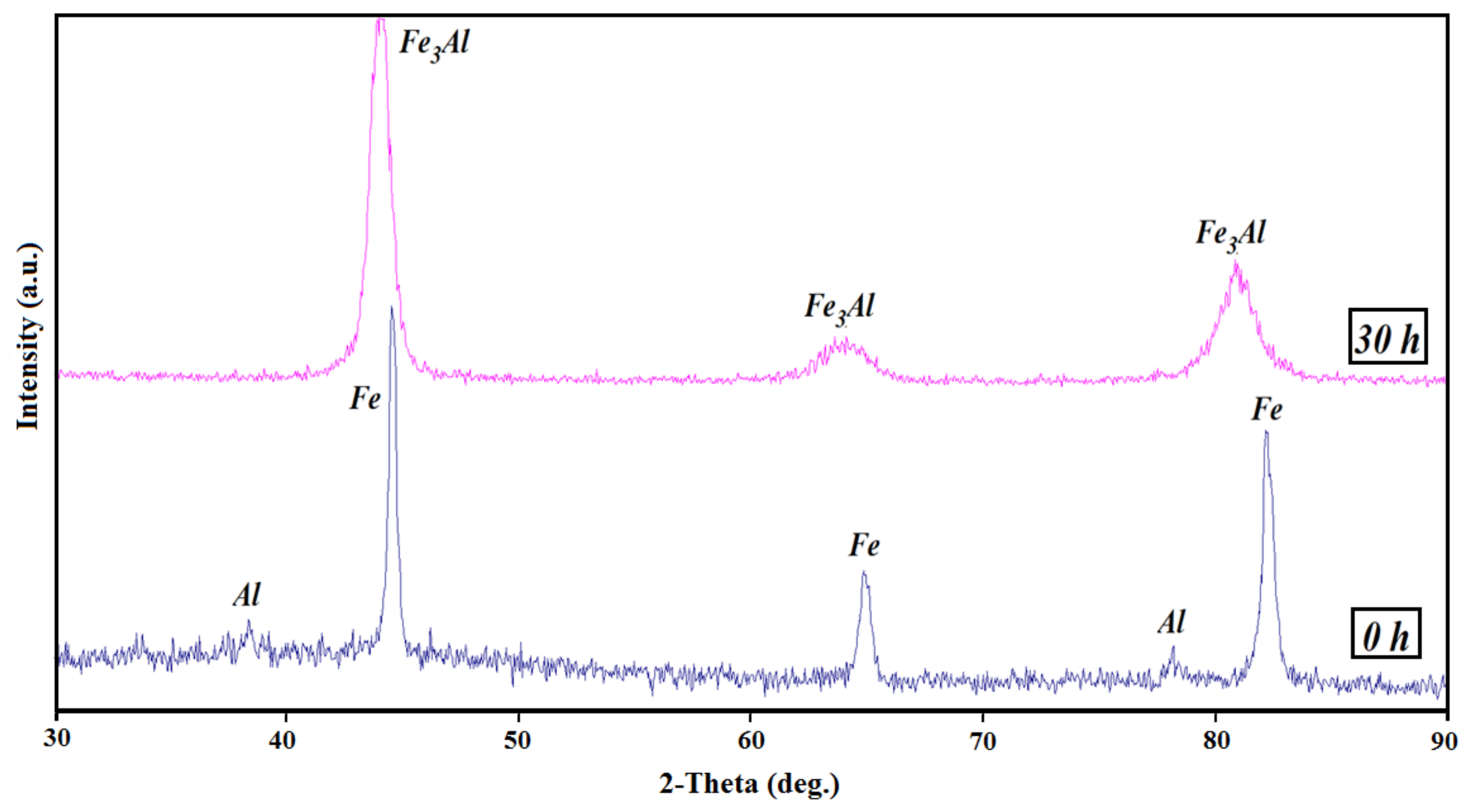
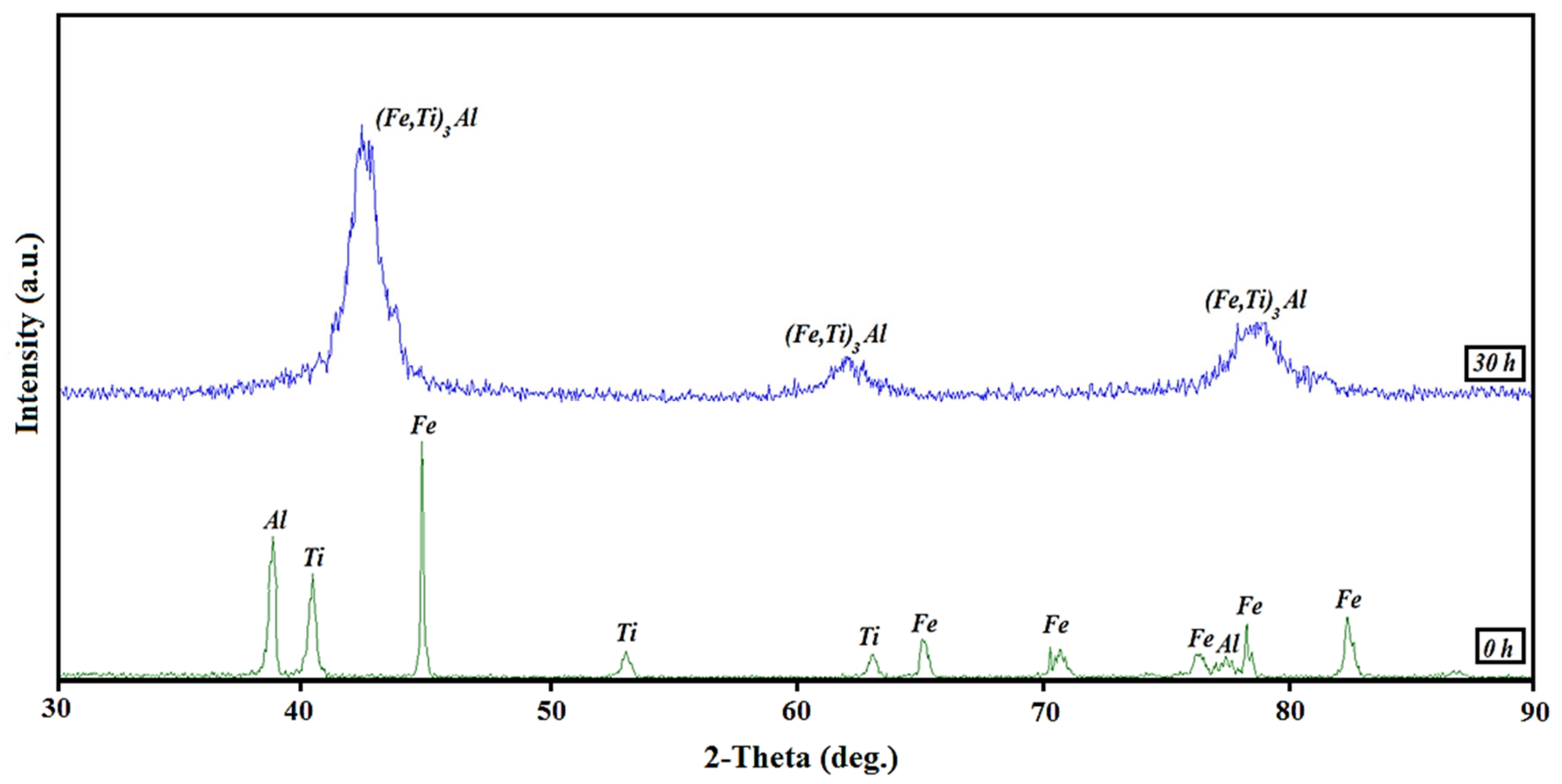
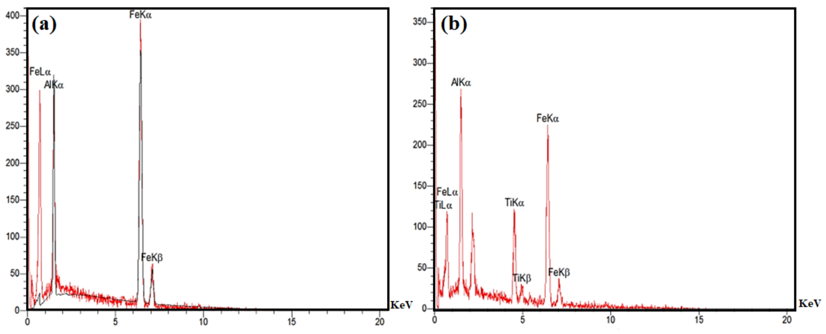
  • Fe3Al with nano-sized grains can be successfully synthesized by 30 h of mechanical alloying. In addition, a nanostructured (Fe,Ti)3Al intermetallic compound can also be formed during mechanical alloying, and it was found that Ti addition leads to the formation of a phase with a smaller grain size.
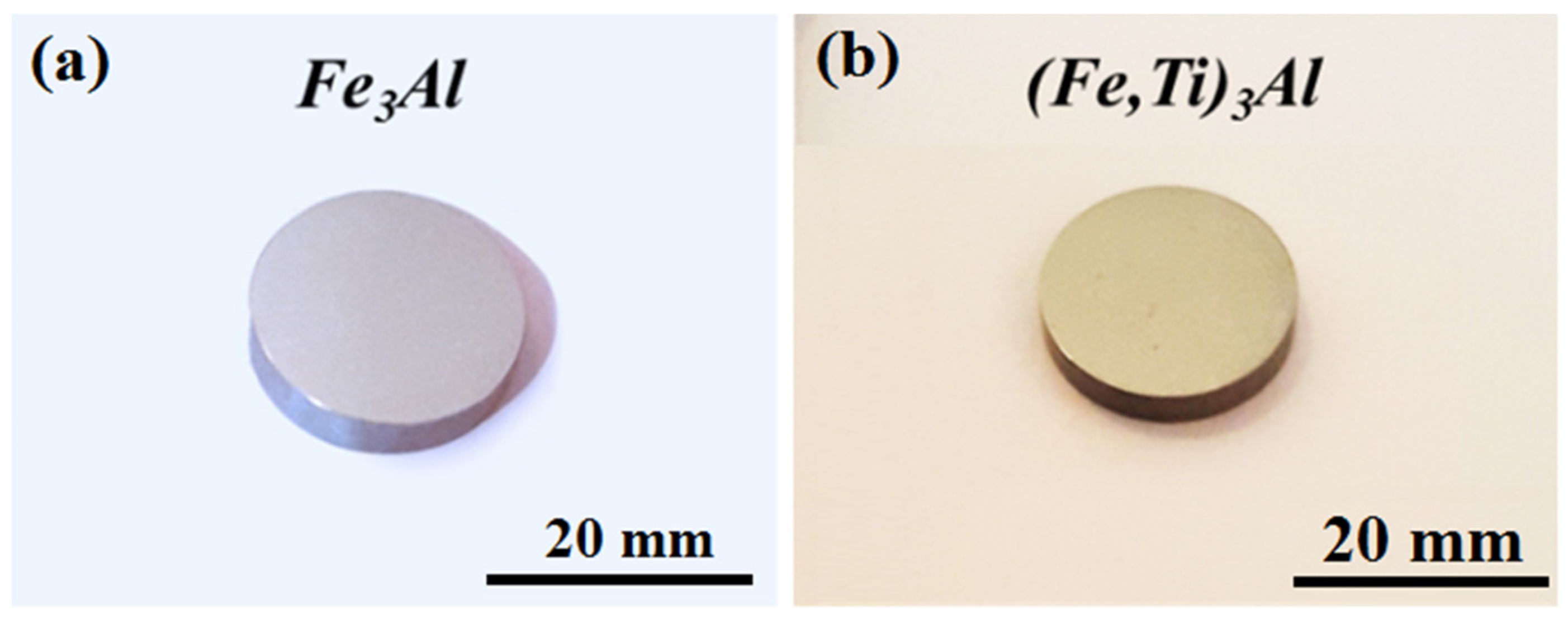
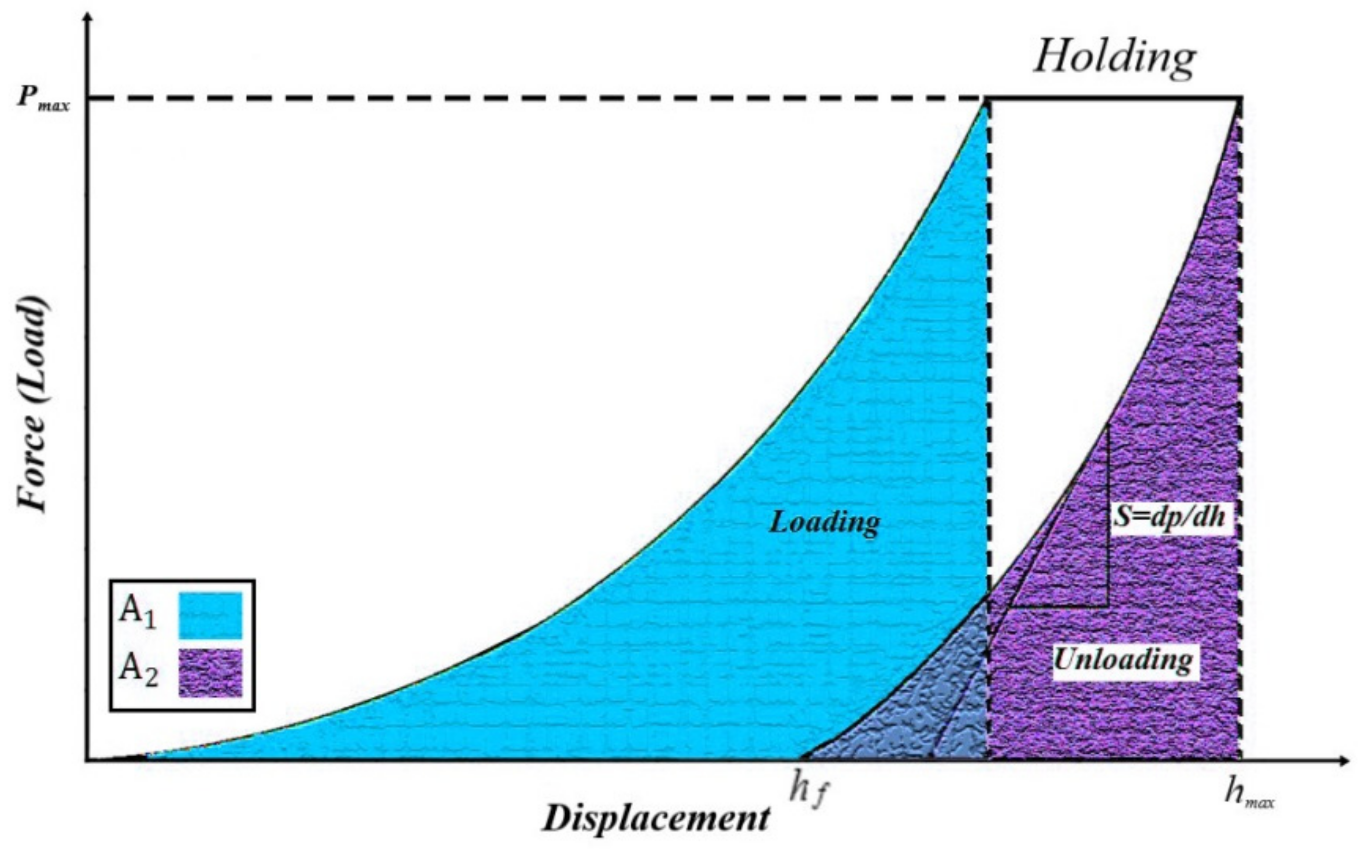
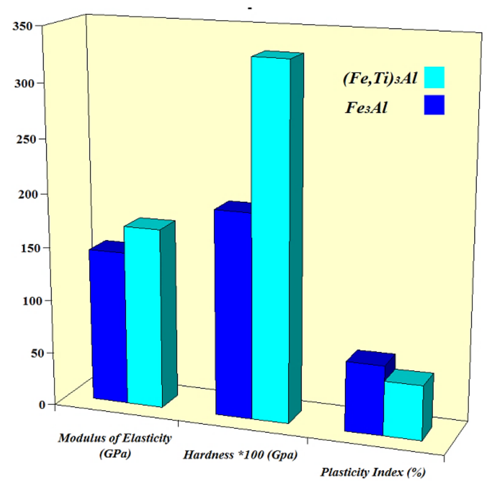
  • Nanostructured Fe3Al and (Fe,Ti)3Al compounds with a nearly full relative density were consolidated by spark plasma sintering without any significant grain growth. Moreover, the nanoindentation test showed that (Fe,Ti)3Al has a higher hardness elasticity modulus than that of the Fe3Al sample, while a decrease in the plasticity index is observed by the addition of Ti to the Fe3Al phase. The increase in the hardness of (Fe,Ti)3Al compared to Fe3Al can be mainly attributed to grain refinement, solid-solution strengthening, and dispersion strengthening.
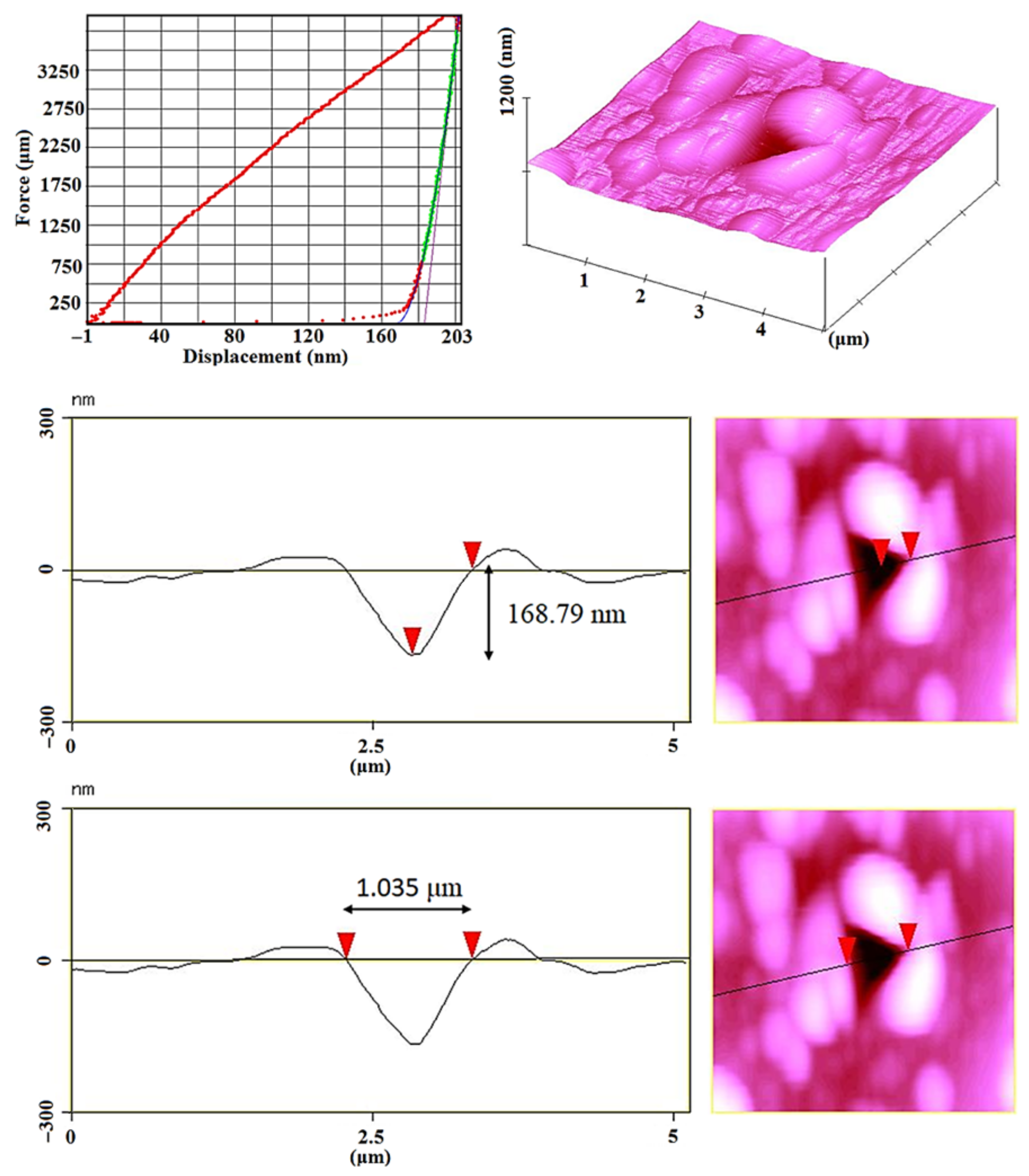
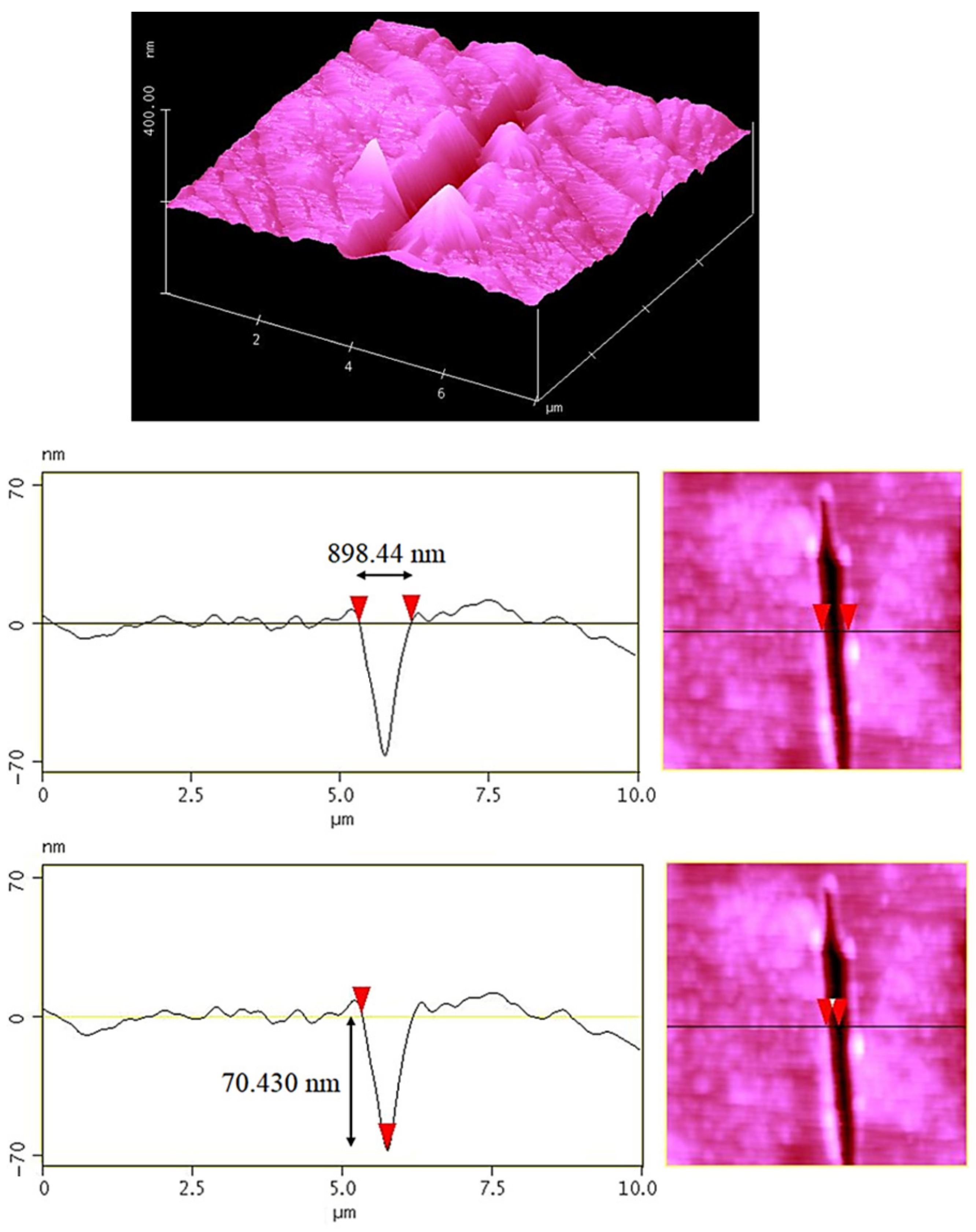
  • The addition of Ti to Fe3Al led to a significant improvement in tribological behavior. This increase was due to more elastic recovery and also less plastic deformation, providing a better scratch resistance in the (Fe,Ti)3Al sample.

Author Contributions

Conceptualization, methodology, writing—original draft preparation, M.M.T., F.B.; Conceptualization, supervision, writing—review and editing, H.M., M.R. and H.R.B.-R.; supervision, writing—review and editing, funding acquisition, F.B., All authors have read and agreed to the published version of the manuscript.

Funding

This research received no external funding.

Institutional Review Board Statement

Not applicable.

Informed Consent Statement

Not applicable.

Data Availability Statement

All data provided in the present manuscript are available to whom it may concern.

Conflicts of Interest

The authors declare no conflict of interest.

References

  1. Zhu, S.-M.; Iwasaki, K. Characterization of mechanically alloyed ternary Fe–Ti–Al powders. Mater. Sci. Eng. A 1999, 270, 170–177. [Google Scholar] [CrossRef]
  2. Rafiei, M.; Enayati, M.H.; Karimzadeh, F. Thermodynamic analysis of solid solution formation in the nanocrystalline Fe–Ti–Al ternary system during mechanical alloying. J. Chem. Thermodyn. 2013, 59, 243–249. [Google Scholar] [CrossRef]
  3. Enayati, M.H.; Salehi, M. Formation mechanism of Fe3Al and FeAl intermetallic compounds during mechanical alloying. J. Mater. Sci. 2005, 40, 3933–3938. [Google Scholar] [CrossRef]
  4. Rafiei, M.; Enayati, M.H.; Karimzadeh, F. Characterization and formation mechanism of nanocrystalline (Fe,Ti)3Al intermetallic compound prepared by mechanical alloying. J. Alloy. Compd. 2009, 480, 392–396. [Google Scholar] [CrossRef]
  5. Williamson, G.; Hall, W. X-ray line broadening from filed aluminium and wolfram. Acta Metall. 1953, 1, 22–31. [Google Scholar] [CrossRef]
  6. Stoloff, N.S. Iron aluminides: Present status and future prospects. Mater. Sci. Eng. A 1998, 258, 1–14. [Google Scholar] [CrossRef]
  7. Pocheć, E.; Jóźwiak, S.; Karczewski, K.; Bojar, Z. Fe–Al phase formation around SHS reactions under isothermal conditions. J. Alloy. Compd. 2011, 509, 1124–1128. [Google Scholar] [CrossRef]
  8. Sina, H.; Corneliusson, J.; Turba, K.; Iyengar, S. A study on the formation of iron aluminide (FeAl) from elemental powders. J. Alloy. Compd. 2015, 636, 261–269. [Google Scholar] [CrossRef]
  9. Krein, R.; Schneider, A.; Sauthoff, G.; Frommeyer, G. Microstructure and mechanical properties of Fe3Al-based alloys with strengthening boride precipitates. Intermetallics 2007, 15, 1172–1182. [Google Scholar] [CrossRef]
  10. Simas, P.; Juan, J.S.; Nó, M.L. High-temperature relaxation analysis in a fine-grain B2 FeAl intermetallic. Intermetallics 2010, 18, 1348–1352. [Google Scholar] [CrossRef]
  11. Dobeš, F.; Kratochvíl, P. The effect of Zr addition on creep of Fe-30 at.% Al alloys. Intermetallics 2013, 43, 142–146. [Google Scholar] [CrossRef]
  12. Senčekova, L.; Palm, M.; Pešička, J.; Veselý, J. Microstructures, mechanical properties and oxidation behaviour of single-phase Fe3Al (D03) and two-phase α-Fe,Al (A2) + Fe3Al (D03) FeAlV alloys. Intermetallics 2016, 73, 58–66. [Google Scholar] [CrossRef]
  13. Emdadi, A.; Sizova, I.; Bambach, M.; Hecht, U. Hot deformation behavior of a spark plasma sintered Fe-25Al-1.5Ta alloy with strengthening Laves phase. Intermetallics 2019, 109, 123–134. [Google Scholar] [CrossRef]
  14. Rafiei, M.; Enayati, M.H.; Karimzadeh, F. Mechanochemical synthesis of (Fe,Ti)3Al–Al2O3 nanocomposite. J. Alloy. Compd. 2009, 488, 144–147. [Google Scholar] [CrossRef]
  15. Wang, J.; Xing, J.; Tang, H.; Yang, B.; Li, Y. Microstructure and mechanical properties of Fe3Al alloys prepared by MA-PAS and MA-HP. Trans. Nonferrous Met. Soc. China 2011, 21, 2408–2414. [Google Scholar] [CrossRef]
  16. Wang, J.; Xing, J.; Cao, L.; Su, W.; Gao, Y. Dry sliding wear behavior of Fe3Al alloys prepared by mechanical alloying and plasma activated sintering. Wear 2010, 268, 473–480. [Google Scholar] [CrossRef]
  17. Deevi, S.C.; Zhang, W.J. Encyclopedia of Materials: Science and Technology; Elsevier Science Ltd.: Amsterdam, The Netherlands, 2001; pp. 4165–4173. [Google Scholar]
  18. Liu, B.; Yang, Q.; Wang, Y. Intereaction and intermetallic phase formation between aluminum and stainless steel. Results Phys. 2019, 12, 514–524. [Google Scholar] [CrossRef]
  19. Alman, D.E.; Hawk, J.A.; Tylczak, J.H.; Doğan, C.P.; Wilson, R.D. Wear of iron–aluminide intermetallic-based alloys and composites by hard particles. Wear 2001, 251, 875–884. [Google Scholar] [CrossRef]
  20. Zhu, S.-M.; Tamura, M.; Sakamoto, K.; Iwasaki, K. Characterization of Fe3Al-based intermetallic alloys fabricated by mechanical alloying and HIP consolidation. Mater. Sci. Eng. A 2000, 292, 83–89. [Google Scholar] [CrossRef]
  21. Wang, J.; Xing, J.; Qiu, Z.; Zhi, X.; Cao, L. Effect of fabrication methods on microstructure and mechanical properties of Fe3Al-based alloys. J. Alloy. Compd. 2009, 488, 117–122. [Google Scholar] [CrossRef]
  22. Deevi, S.C.; Sikka, V.K.; Liu, C.T. Processing, properties, and applications of nickel and iron aluminides. Prog. Mater. Sci. 1997, 42, 177–192. [Google Scholar] [CrossRef]
  23. Zamanzade, M.; Barnoush, A.; Motz, C. A Review on the Properties of Iron Aluminide Intermetallics. Crystals 2016, 6, 10. [Google Scholar] [CrossRef] [Green Version]
  24. Luu, W.C.; Wu, J.K. Moisture and hydrogen-induced embrittlement of Fe3Al alloys. Mater. Chem. Phys. 2001, 70, 236–241. [Google Scholar] [CrossRef]
  25. Zhang, Z.-R.; Liu, W.-X. Mechanical properties of Fe3Al-based alloys with addition of carbon, niobium and titanium. Mater. Sci. Eng. A 2006, 423, 343–349. [Google Scholar] [CrossRef]
  26. Khodaei, M.; Enayati, M.H.; Karimzadeh, F. The structure and mechanical properties of Fe3Al–30 vol.% Al2O3 nanocomposite. J. Alloy. Compd. 2009, 488, 134–137. [Google Scholar] [CrossRef]
  27. Khodaei, M.; Enayati, M.H.; Karimzadeh, F. Mechanochemically synthesized Fe3Al–Al2O3 nanocomposite. J. Alloy. Compd. 2009, 467, 159–162. [Google Scholar] [CrossRef]
  28. Park, N.; Lee, S.-C.; Cha, P.-R. Effects of alloying elements on the stability and mechanical properties of Fe3Al from first-principles calculations. Comput. Mater. Sci. 2018, 146, 303–309. [Google Scholar] [CrossRef]
  29. McKamey, C.G.; DeVan, J.H.; Tortorelli, P.F.; Sikka, V.K. A review of recent developments in Fe3Al-based alloys. J. Mater. Res. 1991, 6, 1779–1805. [Google Scholar] [CrossRef] [Green Version]
  30. Suryanarayana, C. Mechanical alloying and milling. Prog. Mater. Sci. 2001, 46, 1–184. [Google Scholar] [CrossRef]
  31. Suryanarayana, C.; Al-Aqeeli, N. Mechanically alloyed nanocomposites. Prog. Mater. Sci. 2013, 58, 383–502. [Google Scholar] [CrossRef]
  32. Shashanka, R.; Chaira, D. Optimization of milling parameters for the synthesis of nano-structured duplex and ferritic stainless steel powders by high energy planetary milling. Powder Technol. 2015, 278, 34–45. [Google Scholar] [CrossRef]
  33. Shashanka, R.; Chaira, D. Development of nano-structured duplex and ferritic stainless steels by pulverisette planetary milling followed by pressureless sintering. Mater. Charact. 2015, 99, 220–229. [Google Scholar]
  34. Shashanka, R.; Chaira, D. Phase transformation and microstructure study of nano-structured austenitic and ferritic stainless steel powders prepared by planetary milling. Powder Technol. 2014, 259, 125–136. [Google Scholar]
  35. Shashanka, R.; Uzun, O.; Chaira, D. Synthesis of nano-structured duplex and ferritic stainless steel powders by dry milling and its comparision with wet milling. Arch. Metall. Mater. 2020, 65, 5–14. [Google Scholar]
  36. Fair, G.H.; Wood, J.V. Mechanical Alloying of Iron–Aluminium Intermetallics. Powder Metall. 1993, 36, 123–128. [Google Scholar] [CrossRef]
  37. Tang, W.M.; Zheng, Z.X.; Tang, H.J.; Ren, R.; Wu, Y.C. Structural evolution and grain growth kinetics of the Fe–28Al elemental powder during mechanical alloying and annealing. Intermetallics 2007, 15, 1020–1026. [Google Scholar] [CrossRef]
  38. Enzo, S.; Frattini, R.; Gupta, R.; Macrì, P.P.; Principi, G.; Schiffini, L.; Scipione, G. X-ray powder diffraction and Mössbauer study of nanocrystalline FeAl prepared by mechanical alloying. Acta Mater. 1996, 44, 3105–3113. [Google Scholar] [CrossRef]
  39. Morris, D.G.; Morris, M.A. Mechanical properties of FeAl-ZrB2 alloys prepared by rapid solidification. Acta Metall. Mater. 1991, 39, 1771–1779. [Google Scholar] [CrossRef]
  40. McKamey, C.G.; Liu, C.T. Chromium addition and environmental embrittlement in Fe3Al. Scr. Metall. Mater. 1990, 24, 2119–2122. [Google Scholar] [CrossRef]
  41. Yangshan, S.; Zhengjun, Y.; Zhonghua, Z.; Haibo, H. Mechanical properties of Fe3Al-based alloys with cerium addition. Scr. Metall. Mater. 1995, 33, 811–817. [Google Scholar] [CrossRef]
  42. Baligidad, R.G.; Prakash, U.; Radhakrishna, A.; Rao, V.R.; Rao, P.K.; Ballal, N.B. Effect of carbides on embrittlement of Fe3Al based intermetallic alloys. Scr. Mater. 1997, 36, 667–671. [Google Scholar] [CrossRef]
  43. Mostaan, H.; Karimzadeh, F.; Abbasi, M.H. Synthesis and formation mechanism of nanostructured NbAl3 intermetallic during mechanical alloying and a kinetic study on its formation. Thermochim. Acta 2012, 529, 36–44. [Google Scholar] [CrossRef]
  44. Mostaan, H.; Karimzadeh, F.; Abbasi, M.H. Thermodynamic analysis of nanocrystalline and amorphous phase formation in Nb–Al system during mechanical alloying. Powder Metall. 2012, 55, 142–147. [Google Scholar] [CrossRef]
  45. Xu, X.; Tao, T.; Zhang, X.; Cao, Z.; Huang, D.; Liang, H.; Hu, Y. Spark plasma sintering of ZrO2–Al2O3 nanocomposites at low temperatures aided by amorphous powders. Ceram. Int. 2019, 46, 4365–4370. [Google Scholar] [CrossRef]
  46. Pournajaf, R.; Hassanzadeh-Tabrizi, S.A.; Ebrahimi-Kahrizsangi, R.; Alhaji, A.; Nourbakhsh, A.A. Polycrystalline infrared-transparent MgO fabricated by spark plasma sintering. Ceram. Int. 2019, 45, 18943–18950. [Google Scholar] [CrossRef]
  47. Rominiyi, A.L.; Shongwe, M.B.; Ogunmuyiwa, E.N.; Babalola, B.J.; Lepele, P.F.; Olubambi, P.A. Effect of nickel addition on densification, microstructure and wear behaviour of spark plasma sintered CP-titanium. Mater. Chem. Phys. 2020, 240, 122130. [Google Scholar] [CrossRef]
  48. Rafiei, M.; Enayati, M.H.; Karimzadeh, F. The effect of Ti addition on alloying and formation of nanocrystalline structure in Fe–Al system. J. Mater. Sci. 2010, 45, 4058–4062. [Google Scholar] [CrossRef]
  49. Oliver, W.C.; Pharr, G.M.I. Introduction, An improved technique for determining hardness and elastic modulus using load and displacement sensing indentation experiments. J. Mater. Res. 1992, 7, 1564–1583. [Google Scholar] [CrossRef]
  50. Liu, Y.; Chong, X.; Jiang, Y.; Zhou, R.; Feng, J. Mechanical properties and electronic structures of Fe-Al intermetallic. Phys. B Condens. Matter 2017, 506, 1–11. [Google Scholar] [CrossRef]
  51. Friák, M.; Deges, J.; Krein, R.; Frommeyer, G.; Neugebauer, J. Combined ab initio and experimental study of structural and elastic properties of Fe3Al-based ternaries. Intermetallics 2010, 18, 1310–1315. [Google Scholar] [CrossRef]
  52. Deevil, S.C.; Maziasz, P.J.; Sikka, V.K.; Cahn, R.W. International Symposium on Nickel and Iron Aluminides: Processing, Properties, and Applications. Mater. Technol. 1997, 12, 165–170. [Google Scholar] [CrossRef]
  53. Zhu, S.-M.; Sakamoto, K.; Tamura, M.; Iwasaki, K. Effects of Titanium Addition on the Microstructure and Mechanical Behavior of Iron Aluminide Fe3Al. Mater. Trans. 2001, 42, 484–490. [Google Scholar] [CrossRef] [Green Version]
  54. Morris, M.A.; Morris, D.G. Dispersoid additions and their effect on high temperature deformation of Fe-Al. Acta Metall. Mater. 1990, 38, 551–559. [Google Scholar] [CrossRef]
  55. Dasari, A.; Yu, Z.-Z.; Mai, Y.-W. Nanoscratching of nylon 66-based ternary nanocomposites. Acta Mater. 2007, 55, 635–646. [Google Scholar] [CrossRef]
  56. Popov, V. Several Aspects of Application of Nanodiamonds as Reinforcements for Metal Matrix Composites. Appl. Sci. 2021, 11, 4695. [Google Scholar] [CrossRef]
  57. Bai, Y.; Li, M.; Cheng, C.; Li, J.; Guo, Y.; Yang, Z. Study on Microstructure and In Situ Tensile Deformation Behavior of Fe-25Mn-xAl-8Ni-C Alloy Prepared by Vacuum Arc Melting. Metals 2021, 11, 814. [Google Scholar] [CrossRef]
  58. Salman, K.D.; Al-Maliki, W.A.K.; Alobaid, F.; Epple, B. Microstructural Analysis and Mechanical Properties of a Hybrid Al/Fe2O3/Ag Nano-Composite. Appl. Sci. 2022, 12, 4730. [Google Scholar] [CrossRef]
  59. Voiculescu, I.; Geanta, V.; Stefanescu, E.V.; Simion, G.; Scutelnicu, E. Effect of Diffusion on Dissimilar Welded Joint between Al0.8CoCrFeNi High-Entropy Alloy and S235JR Structural Steel. Metals 2022, 12, 548. [Google Scholar] [CrossRef]
  60. Wang, S.; Chen, L.; Li, Q.; Wang, S.; Wu, M.; Yang, S.; Xiang, D. Effects of Al or Mo Addition on Microstructure and Mechanical Properties of Fe-Rich Nonequiatomic FeCrCoMnNi High-Entropy Alloy. Metals 2022, 12, 191. [Google Scholar] [CrossRef]
  61. Cui, C.; Nie, J.; Li, Y.; Guan, Q.; Cai, J.; Zhang, P.; Wu, J. Wear Resistance of FeCrAlNbNi Alloyed Zone via Laser Surface Alloying on 304 Stainless Steel. Metals 2022, 12, 467. [Google Scholar] [CrossRef]
  62. Romero-Orozco, A.J.; Taha-Tijerina, J.J.; de Luna-Alanís, R.; López-Morelos, V.H.; Ramírez-López, M.; Salazar-Martínez, M.; Curiel-López, F.F. Evaluation of Microstructural and Mechanical Behavior of AHSS CP780 Steel Welded by GMAW-Pulsed and GMAW-Pulsed-Brazing Processes. Metals 2022, 12, 530. [Google Scholar] [CrossRef]
  63. He, Z.; Hu, X.; Han, W.; Mao, X.; Chou, K.-C. Erosion Layer Growth between Solid 316L Stainless Steel and Al–Li Alloy Melt. Metals 2022, 12, 350. [Google Scholar] [CrossRef]
  64. Ananiadis, E.; Argyris, K.T.; Matikas, T.E.; Sfikas, A.K.; Karantzalis, A.E. Microstructure and Corrosion Performance of Aluminium Matrix Composites Reinforced with Refractory High-Entropy Alloy Particulates. Appl. Sci. 2021, 11, 1300. [Google Scholar] [CrossRef]
  65. Feng, K.; Yang, M.; Long, S.-L.; Li, B. The Effect of a Composite Nanostructure on the Mechanical Properties of a Novel Al-Cu-Mn Alloy through Multipass Cold Rolling and Aging. Appl. Sci. 2020, 10, 8109. [Google Scholar] [CrossRef]
  66. Mudang, M.; Hamzah, E.; Bakhsheshi-Rad, H.R.; Berto, F. Effect of heat treatment on microstructure and creep behavior of Fe-40Ni-24Cr alloy. Appl. Sci. 2021, 11, 7951. [Google Scholar] [CrossRef]
  67. Fang, C.; Souissi, M.; Que, Z.; Fan, Z. Crystal Chemistry and Electronic Properties of the Al-Rich Compounds, Al2Cu, ω-Al7Cu2Fe and θ-Al13Fe4 with Cu Solution. Metals 2022, 12, 329. [Google Scholar] [CrossRef]
  68. Abazari, S.; Shamsipur, A.; Bakhsheshi-Rad, H.R.; Ramakrishna, S.; Berto, F. Graphene family nanomaterial reinforced magnesium-based matrix composites for biomedical application: A comprehensive review. Metals 2020, 10, 1002. [Google Scholar] [CrossRef]
  69. Saberi, A.; Bakhsheshi-Rad, H.R.; Ismail, A.F.; Sharif, S.; Razzaghi, M.; Ramakrishna, S.; Berto, F. The Effect of Co-Encapsulated GO-Cu Nanofillers on Mechanical Properties, Cell Response, and Antibacterial Activities of Mg-Zn Composite. Metals 2022, 12, 207. [Google Scholar] [CrossRef]
  70. Badkoobeh, F.; Mostaan, H.; Rafiei, M.; Bakhsheshi-Rad, H.R.; Berto, F. Microstructural Characteristics and Strengthening Mechanisms of Ferritic–Martensitic Dual-Phase Steels: A Review. Metals 2022, 12, 101. [Google Scholar] [CrossRef]
  71. Abazari, S.; Shamsipur, A.; Bakhsheshi-Rad, H.R.; Ismail, A.F.; Sharif, S.; Razzaghi, M.; Ramakrishna, S.; Berto, F. Carbon nanotubes (CNTs)-reinforced magnesium-based matrix composites: A comprehensive review. Materials 2020, 13, 4421. [Google Scholar] [CrossRef]
  72. Badkoobeh, F.; Mostaan, H.; Rafiei, M.; Bakhsheshi-Rad, H.R.; Berto, F. Friction Stir Welding/Processing of Mg-Based Alloys: A Critical Review on Advancements and Challenges. Materials 2021, 14, 6726. [Google Scholar] [CrossRef] [PubMed]
  73. Cheng, J.; Yun, Y.; Rui, J. Enhanced Tensile Plasticity in Ultrafine Lamellar Eutectic Al-Cu Based Composites with α-Al Dendrites Prepared by Progressive Solidification. Appl. Sci. 2019, 9, 3922. [Google Scholar] [CrossRef] [Green Version]
Figure 1. The prepared nanostructure (a) Fe3Al and (b) (Fe,Ti)3Al compounds produced by the SPS method.
Metals 12 01077 g001
Figure 2. Results of XRD analysis of Fe75Al25 powder mixture before and after 30 h of milling time.
Metals 12 01077 g002
Figure 3. XRD analysis of Fe50Al25Ti25 powder mixtures before and after mechanical alloying.
Metals 12 01077 g003
Figure 4. XRD patterns of powder mixtures after spark plasma sintering; (a) Fe3Al and (b) (Fe,Ti)3Al.
Metals 12 01077 g004
Figure 5. EDS analysis of the bulk samples (after SPS process); (a) Fe3Al and (b) (Fe, Ti)3Al compounds.
Metals 12 01077 g005
Figure 6. Force-displacement curve in a nano-indentation test.
Metals 12 01077 g006
Figure 7. Loading–unloading curve, AFM image and its associated cross section for Fe3Al sample.
Metals 12 01077 g007
Figure 8. Loading–unloading curve, AFM image, and its associated cross section for a (Fe,Ti)3Al sample.
Metals 12 01077 g008
Figure 9. Mechanical properties of Fe3Al and (Fe,Ti)3Al determined using nano-indentation tests.
Metals 12 01077 g009
Figure 10. AFM image of a scratch from an Fe3Al sample and its associated cross section.
Metals 12 01077 g010
Figure 11. AFM image of a scratch from (Fe,Ti)3Al and its associated cross section.
Metals 12 01077 g011
Figure 12. SEM images from scratch grooves in Fe3Al and (Fe,Ti)3Al samples.
Metals 12 01077 g012
Table 1. The mechanical properties of the nanostructure Fe3Al and (Fe,Ti)3Al compounds.
SampleElastic Modulus (GPa)Hardness × 100Plasticity Index (%)
Fe3Al144 ± 41.92 ± 0.150.65 ± 0.02
(Fe,Ti)3Al169 ± 33.29 ± 0.20.51 ± 0.02
Publisher’s Note: MDPI stays neutral with regard to jurisdictional claims in published maps and institutional affiliations.

