Article

Susceptibility of Dissimilar IN600 Welded Joints to Stress Corrosion Cracking Using Slow Strain Rate Test in Sodium Electrolytes

by
Heriberto Granados-Becerra
1,
Víctor H. López-Morelos
1,*,
Antonio Contreras
2,
Francisco Fernando Curiel-López
1,
Rafael García-Hernández
1,
Jorge Antonio González-Sánchez
3 and
Eduardo Cortés
1
1
Instituto de Investigación en Metalurgia y Materiales, Universidad Michoacana de San Nicolás de Hidalgo, Edificio “U”, Ciudad Universitaria, Morelia 58030, Mexico
2
Instituto Mexicano del Petróleo, Eje Central Lázaro Cárdenas Norte 152, Colonia San Bartolo Atepehuacan, Alcaldia Gustavo A. Madero, Ciudad de Mexico 07730, Mexico
3
Centro de Investigación en Corrosión, Universidad Autónoma de Campeche, Av. Heroe de Nacozari 480, Campeche 24079, Mexico
*
Author to whom correspondence should be addressed.
Metals 2022, 12(7), 1112; https://doi.org/10.3390/met12071112
Submission received: 3 June 2022 / Revised: 23 June 2022 / Accepted: 24 June 2022 / Published: 28 June 2022
(This article belongs to the Special Issue Corrosion and Protection in Aeronautical Alloys)

Abstract

:
The stress corrosion cracking (SCC) behavior of aged plates of Inconel 600 welded to Inconel 600 plates in the as-received condition was studied using the slow strain rate test (SSRT) in two sodium containing electrolytes at 25 and 80 °C. The aged plate was used to simulate damage by the operation service. Electrochemical noise (EN) was used to monitor the SCC. The plates were gas metal arc welded (GMAW) employing ERNiCrMo-3 and ER310 filler wires along with 95% Ar + 3% N2 + 2% O2 and 97% Ar + 3% N2 as the shielding gas, respectively. The microstructure of the welded joints was characterized using optical and scanning electron microscopy. The results of the SCC revealed that when sodium thiosulfate was used, the loss in plasticity was higher in the NiCrMo-3 joint with around a 20 percent decrease. Conversely, in the 310 welds, the loss in plasticity was higher in the sodium hydroxide, which diminished by 12 percent. A few secondary microcracks were observed in the transversal section in specimens of both welds. The results of the EN showed an increase in the potential and current when the sample reached the tensile strength and then decreased when the neck was formed; these changes indicate that some events occurred during the SSRT. The EN data showed two types of corrosion: general corrosion for NiCrMo-3 and mixed corrosion for the 310 welded joint in both environments. Electrochemical polarization was also employed to understand the mechanism of SCC.

1. Introduction

Inconel 600 (IN600) is a Ni-based alloy with high contents of Cr and Fe, elements that confer strength to the alloy via a solid solution mechanism. The attractive mechanical and corrosion properties exhibited by IN600 make it suitable for different applications in the nuclear, aerospace, and chemical industries. Different studies support the excellent properties and mechanical behavior of the Inconel 600 alloy as reported by Al-Rubaie [1], who described the fatigue crack growth of Inconel 600, whereas Chandrasekar [2] studied the effect of surface pretreatment before the ATIG welding of Inconel 600 and Kwon [3] reported the fretting fatigue life of Inconel 600 at high temperature. Ru et al. [4] reported that Inconel could be used in the mill annealed condition or heat treated because of its superior performance compared with other corrosion resistance alloys. Zhang [5] studied the effect of Cr carbide precipitation at the grain boundaries and within the grains during extended exposure at high temperatures on the fretting wear in IN600. Lim et al. [6] observed that the precipitation of Cr carbides occurred preferentially in high-energy zones at the grain boundaries. In his study, Abraham [7] corroborated that the mechanism of precipitation was principally due to the low solubility of C in the Ni matrix and the high thermodynamic affinity of Cr to form compounds of different stoichiometry with C. The formation of Cr-rich carbides in IN600 may reduce the solid solution strengthening mechanism and lead to a loss in the intergranular corrosion resistance (IGCR) of the alloy. Yoo et al. [8] reported that the precipitation of chromium carbides, namely, Cr7C3 and Cr23C6, in IN600 occurred in the temperature range of 550–1050 °C, but it might also occur at lower temperatures after very long exposures during service. The behavior and microstructural characterization of IN600 welds have been studied using a variety of filler materials and welding processes [2,7,9,10,11,12]. When alloys are welded, a variety of microstructural changes take place at the base material (BM), leaving a heat affected zone (HAZ) with different microstructural features at each side of the welded joint. In the case of heat and corrosion resistant alloys, the mechanical and corrosion behavior will be negatively affected and designers must be aware about this. After a long time in service, super alloys such as IN600, which are used as structural support or fluid transportation, start to fail and in the majority of cases, the mechanical integrity of the component becomes risky to the staff. Monitoring and supervising materials in operation have to be an important practice for the safety in any industry. The damage might be due to the prevailing environmental conditions, applied load, mechanical fatigue, temperature, and wear. To guarantee the mechanical integrity, it may be restored by two paths: the first one is totally changing the damaged component and the second is the replacement of one part of the component. The advantage of the second is the reduction in the associated cost in the repairs. Some studies have assessed the welding viability of service damaged or degraded materials to as-received (AR) non used or dissimilar materials. Bhaduri et al. [13] evaluated the welding repair procedures for steels with different contents of Cr and Mo to establish the best welding parameters. Other research has focused on studying the effect of microstructure evolution during welding on the mechanical properties of dissimilar welds such as the work reported by Pandey [14]. Shi [15] evaluated the effect of aging in service on the hot ductility of heat-resistant stainless steel castings and found that the loss of repair weldability after service exposure could be related to the loss of ductility. For example, Wang et al. [16] aged a T23 steel after welding for 3000 h in a temperature range from 500 to 650 °C. The authors found that when the steel was welded in the as-received condition, the mechanical properties were similar in comparison with the aged welded plates, but a decrease in the microhardness and toughness was observed. The decrease was attributed to the formation of niobium and vanadium carbides at 650 °C while the formation of Cr23C6 showed a negligible effect.
Stress corrosion cracking (SCC) is the net result of exposing metallic materials in corrosive environments, while at the same time, tensile stresses are being applied and/or high residual stresses are present, resulting in the nucleation and sub-critical growth of cracks, inducing the failure of the material. Faichuk et al. [17] reported that the properties of passive films formed on Alloy 600 at different passive potentials contained a bilayer oxide, whose composition changed as a function of the applied potential, which played a great role in the susceptibility of suffering SCC. Some factors of the welding parameters used might have an impact on SCC behavior, for example, the boundary between the weld metal and the HAZ may be a place for crack initiation and/or a barrier for crack propagation. Furthermore, if the corrosion resistance in the HAZ has been compromised by excessive heat input, the risk of the welded joint to undergo SCC may be increased, as this zone is prone to intergranular corrosion (IGC). Moreover, the microstructural characteristics of the weld metal also play an important role in the SCC behavior depending on the direction of the dendritic growth [18,19]. Considering the effect of SCC in welding, several studies have been performed using dissimilar materials in the as-received condition and some techniques have been used to monitor the SCC process [19,20,21,22]. Nevertheless, only a few studies have been carried out to evaluate the effect of SCC in IN600 welded joints [8]. As there is insufficient literature with respect to the replacement of a partial component, the purpose of the present study was to investigate the susceptibility of IN600 to SCC using the slow strain rate test in welds of nickel alloys and ensure the mechanical integrity when a partial repair of components under service for extended periods of time underwent thermal damage. The assessment was performed in two near neutral environments commonly found in some industries.

2. Materials and Methods

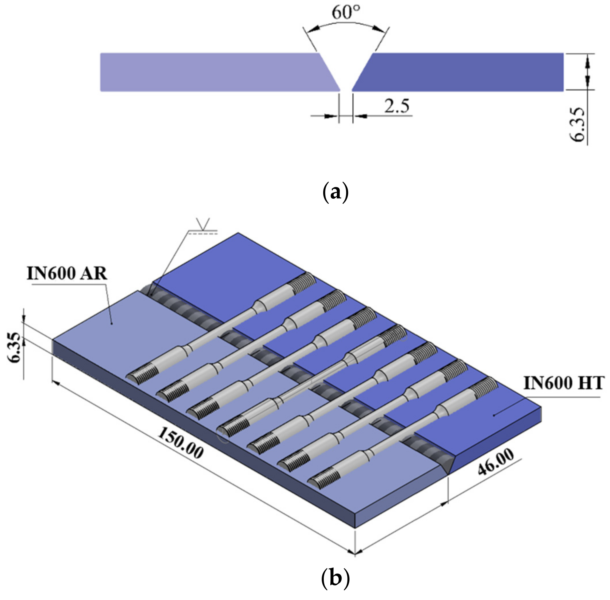
2.1. Materials and Welding Process

In the current study, 6.35 mm thick plates of IN600 with the chemical composition shown in Table 1 were used. The chemical composition was checked by optical emission spectroscopy (OES) and the analysis drew very low contents of elements such as Mo, Nb, N, W, V, Mg, and Co with a total weight of 0.27%. In order to simulate thermal aging in IN600 during service, pieces of the alloy in the as-received (AR) condition from the supplier were heat-treated (HT) at 700 °C in a muffle furnace for 300 h and quenching in water. AR plates were gas metal arc welded (GMAW) to HT plates using a Miller Dimension 652 power source machine. Prior to welding, the plates were machined for a single V-groove butt joint, as schematically shown in Figure 1a. Maintaining an appropriate distance between plates will help to achieve the full penetration particularly with the low fluidity Ni-based filler; for this reason, a root gap of 2.5 mm was chosen. ER310 and ERNiCrMo-3 filler wires of 1.2 mm in diameter were employed and their chemical compositions are also listed in Table 1. Gas mixtures of 97%Ar + 3%N2 and 95%Ar + 3%N2 + 2%O2 were supplied at 18 L/min to shield the weld pool while welding with the ER310 and ERNiCrMo-3 electrodes, respectively. The filler wires were fed at 120 mm/s. A constant potential power source was employed and to succeed in the fusion welding of the butt joints, 1.286 and 1.75 kJ/mm were input for the ER310 and ERNiCrMo-3 electrodes, respectively.

2.2. Microstructural Characterization

Microstructural characterization of the IN600 base materials and welded joint was performed by optical (Zeiss Axio Observer 7 Materials, Carl Zeiss Microscopy, Oberkochen, Germany) and electronic (field emission gun scanning electron microscope, Jeol 7600F, Jeol Ltd., Tokyo, Japan, equipped with energy dispersive X-ray detector, XFlash Detector 6|10, Bruker AXS GmbH, Berlin, Germany) microscopy. The samples were ground using standard metallographic techniques and electropolished with 10–20% perchloric acid in ethanol at 13 V for 20–30 s. Subsequently, the samples were electro etched in 10% sulfuric acid at 3 V for 8 s.

2.3. Slow Strain Rate Tests (SSRTs)

SSRTs were carried out on cylindrical samples (as can be noted in Figure 1b,c) by using the InterCorr mobile constant extension rate test (MCERT) machine (InterCorr International, Inc., Houston, TX, USA) at a strain rate of 10−6 s−1 in air for reference and in aqueous solutions of 0.1 M of Na2S2O3 and 5 M of NaOH at room temperature (RT) and at 80 °C. In some cases, the test was repeated twice to verify reproducibility. The load capacity of the MCERT machine is 44 kN and has a total extension of 50 mm. No cathodic or anodic potential was applied during the SSRTs. The SSRTs were monitored using electrochemical noise (EN) at a frequency of 1 Hz in a potentiostat/galvanostat Gill AC (ACM Instruments, Inc., Cumbria, UK) with a thermal control unit. The EN setup was performed in an arrangement with the specimens as the working electrode (WE), the platinum electrode as a second working electrode (WE2), and saturated calomel electrode (SCE) as the reference electrode. The EN data were analyzed to evaluate the localization index (LI) and transients of the current and potential. Prior to performing the SSRTs, the samples were immersed in the testing solution and the open circuit potential was recorded for 40 min. The electrolyte container was a glass autoclave that was hermetically sealed. Electrochemical potentiodynamic polarization was performed in the as-welded samples in both environments and temperatures. A conventional three electrode electrochemical cell was used, but in this instance, a graphite bar was used as the counter electrode (CE). The susceptibility to SCC was measured with the following expressions:
I S C C = 1 n × I F R A G + I P E + I δ + I σ y , 0.2 % + I R T + I ε + I T F
where:
IFRAG = Fragility index.
IPE = Reduction of plastic elongation index.
Iδ = Loss of plasticity.
I σ y , 0.2 % = Reduction of yield stress index.
IRT = Reduction of UTS index.
Iε = Reduction of plastic deformation index.
ITF = Reduction of time to failure index.
From Equation (1), each index “I” was calculated with respect to the reference environment (air) as follows:
I = x f a i r x f e l e c t r o l i t e x f a i r
where “xf” represents the final results in each environment.
The loss of plasticity was calculated as the ratio of the final elongation in the testing environment, δelectrolite, to the elongation of the specimen in the reference environment, δair, as given in Equation (3).
I δ = 1 δ e l e c t r o l i t e δ a i r
Finally, after the SSRTs, the fractured specimens were cut with a diamond blade and meticulously observed in the scanning electron microscope (SEM) along the length of the gauge section and in the fractured surface.

3. Results and Discussion

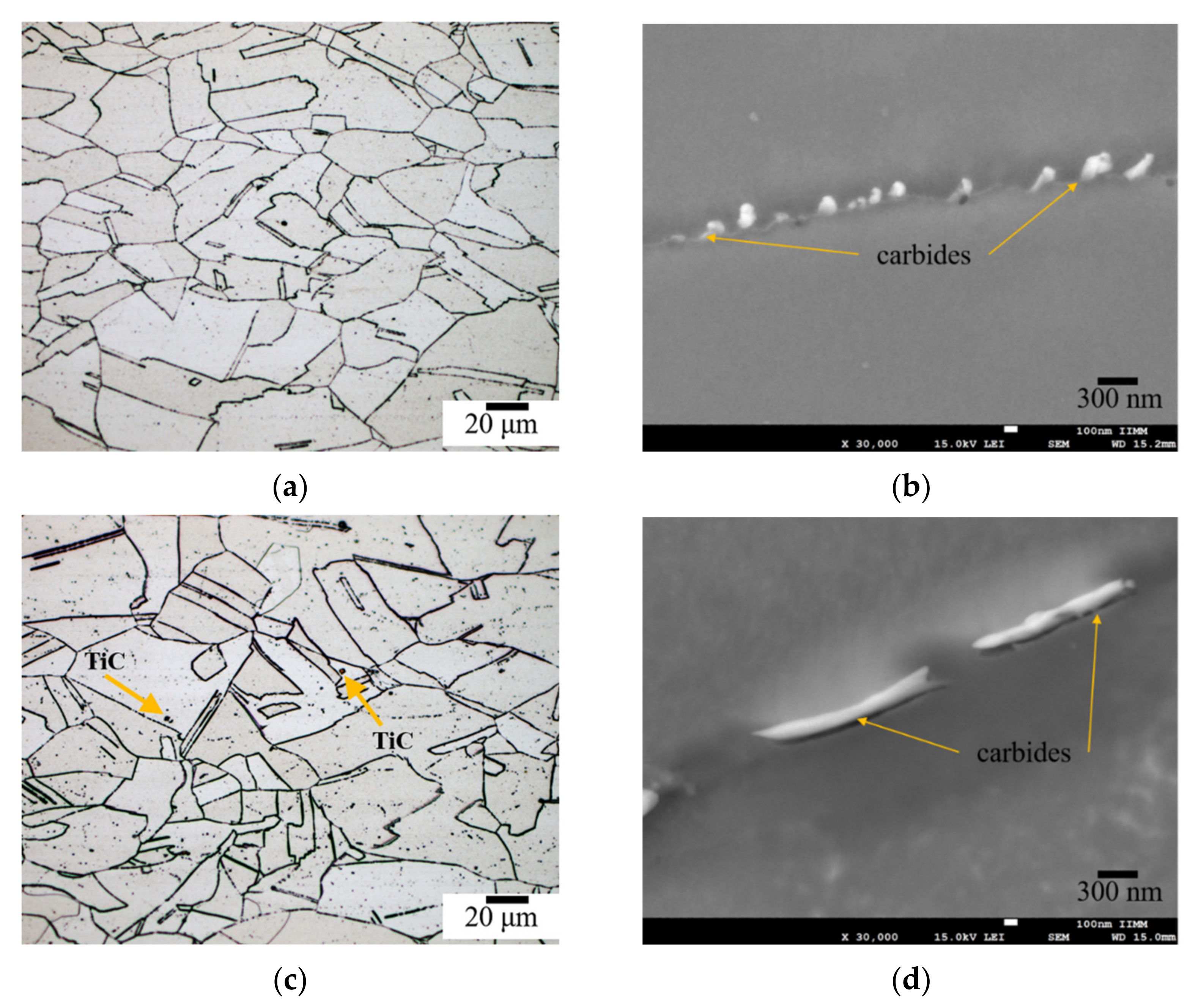
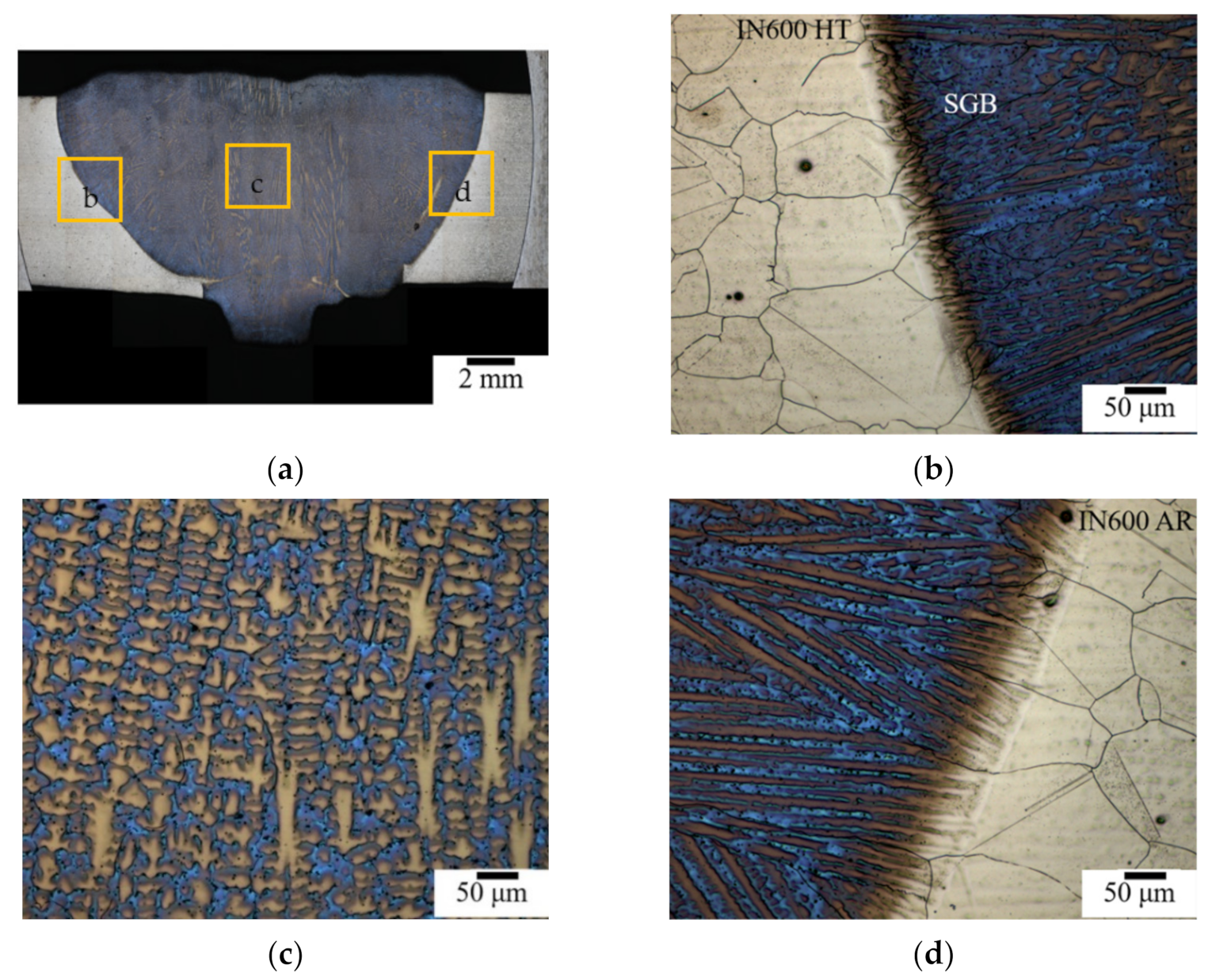
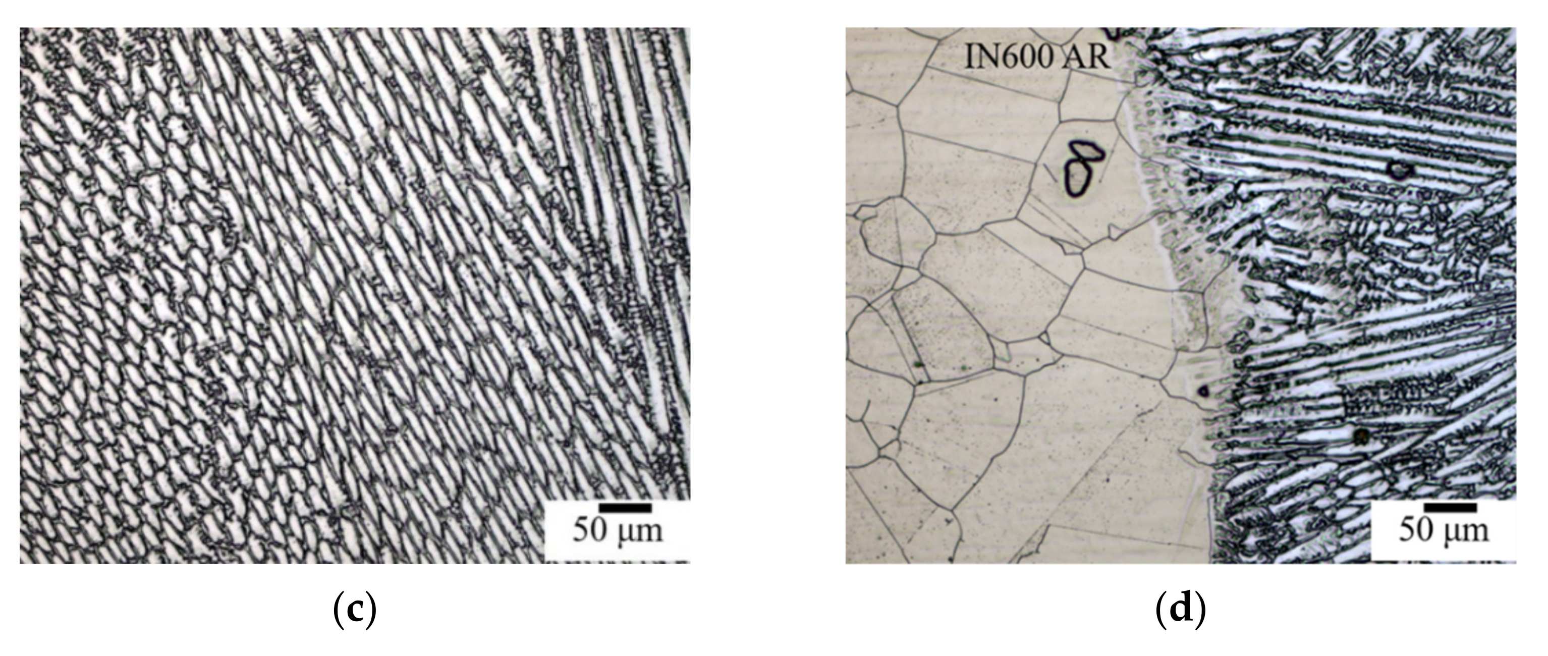
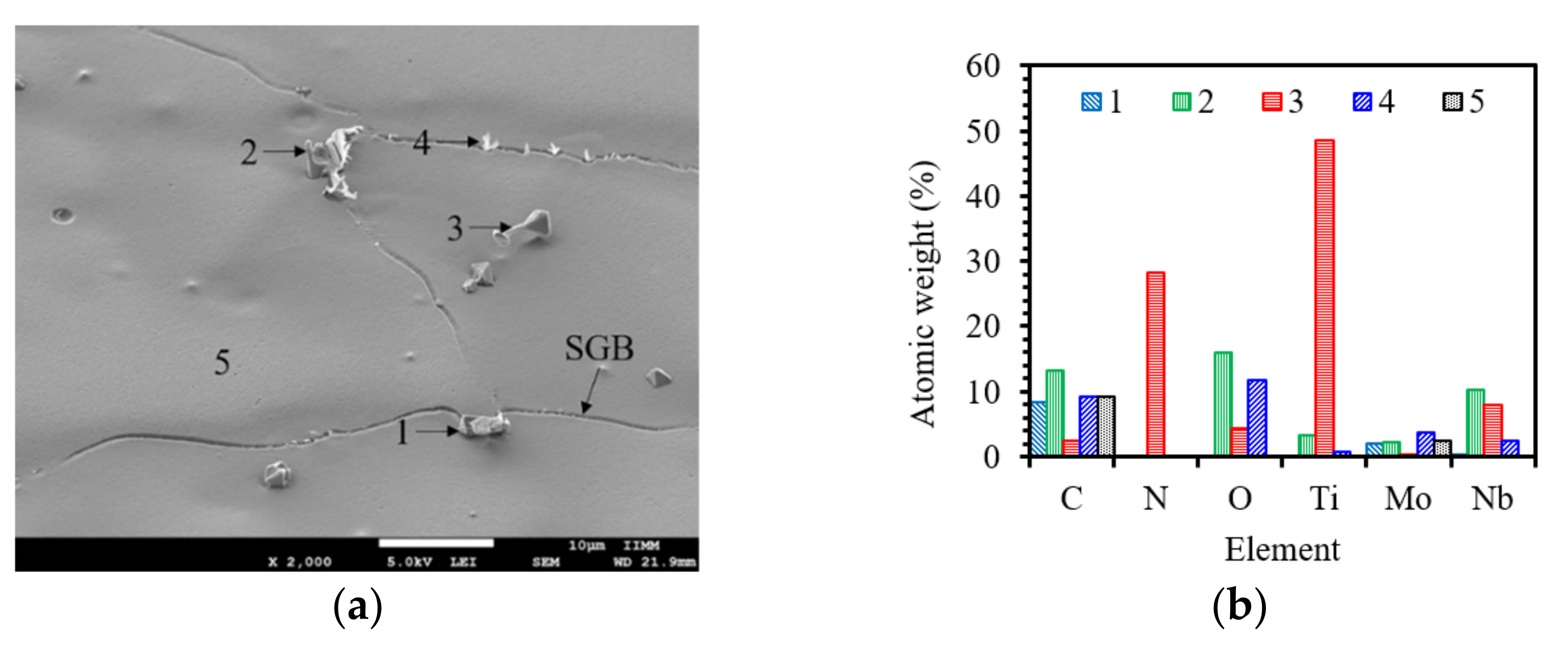
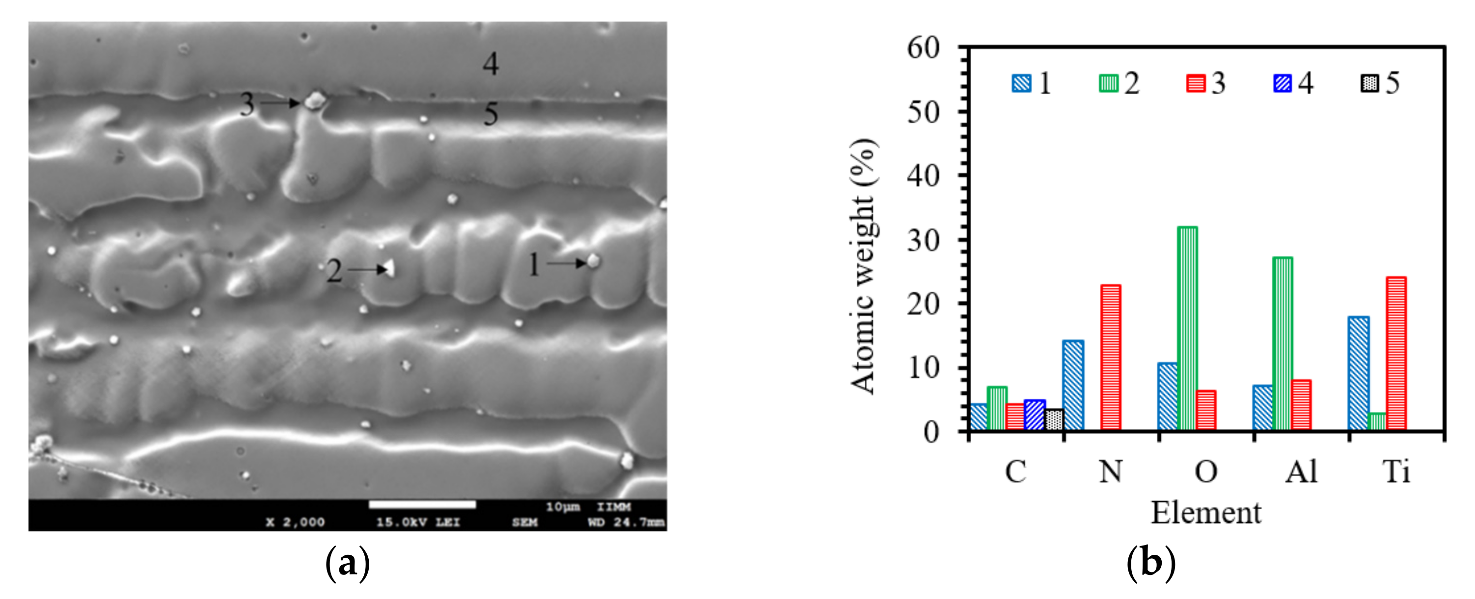
3.1. Microstructure of the Base Metal and Welds

Aged plates of IN600 were gas metal arc welded (GMAW) to plates in the AR condition. Figure 2 shows the microstructure of the base metal in the AR condition and after 300 h of thermal exposure at 700 °C. As can be seen in the optical micrographs, the samples of the base metal showed a fully austenitic matrix with irregular and some equiaxed grains and twinning. In Figure 2a,c, some particles of sizes from 1 to 5 μm (those indicated by the arrows in the images) could be observed in the grain boundaries or inside the grains. Energy dispersive X-ray (EDX) analysis in the SEM indicated that these particles corresponded to TiC and NbC. Another feature that could be seen in Figure 2c was the prior-austenitic grain boundaries (PAGB) as revealed by the etching process. According to Da Silva et al. [23], the PAGB are zones where there is some segregation of alloying elements such as C, P, and Mn. Nishikawa et al. [24] reported that the segregation of P in the IN600 alloys played a crucial role in the susceptibility to stress corrosion cracking (SCC), and that an increase in the P concentration may increase the susceptibility to SCC. Therefore, if P is allocated in specific areas such as the PAGB, these zones will be susceptible to SCC.
Consistent with a previous study [10], carbides of different stoichiometries were seen, namely, M23C6 allocated at the grain boundaries and twins, MC and M7C3 carbides appeared mainly within the austenitic grains. The carbide formation in the limit of the grains was observed in the AR and HT IN600 in the SEM images shown Figure 2b,d, respectively, which were acquired in secondary electron mode. Wang et al. [25] demonstrated that the grain boundary carbides only caused a significant loss in the reduction in area, but, otherwise had little effect on the other tensile properties on IN600. Kikuchi et al. [26] reported that though IN600 usually exhibits paramagnetic properties, it shows ferromagnetic properties along the grain boundaries when chromium depletion occurs. This means that magnetic nondestructive evaluation of sensitization is possible. In this sense, when IN600 is subjected to HT at temperatures between 400 to 1000 °C, the Cr will diffuse to the grain boundaries and react with C, forming Cr-rich carbides, thus making the alloy susceptible to sensitization. The carbide formation in the AR condition is due to the annealing treatment during secondary processing and the size and shape of the particles might vary. After aging at high temperature, more carbides nucleated, the preexistent ones became coarser, and some coalesced. The formation of carbides in some alloys may improve the SCC resistance because they act as blocky tip cracks [27,28]. Cr depletion may affect the mechanical behavior of the alloy during service, since it is known that Cr is found in a solid solution in the Ni matrix. When Cr is relegated to the grain boundaries, it might cause a decrease in the solid solution hardening effect. The formation of carbides along the grain limits was in a serrated way, which may be helpful in the reduction of the susceptibility to SCC (see Figure 2b).
Two different types of filler metal compatible to IN600 with the same crystalline structure, similar corrosion properties, and close mechanical properties were used with the aim to assess the susceptibility to SCC of an IN600 welded joint when the alloy was reused after some metallurgical damage during operation. The microstructure of each weld is shown in Figure 3 and Figure 4. The welded joints of super alloys are prone to cracking, porosity formation, the formation of non-metallic inclusions, the lack of penetration, lack of fusion, and undercut. Therefore, it is important, in principle, to ensure sound welds. The factors that might have a high influence in the SCC resistance of welded joints are the fusion line, non-mixed zones, the HAZ, and the transition zone between the HAZ and the unaffected base metal. In particular, the susceptibility to SCC can be raised when the HAZ is prone to intergranular corrosion (IG). Furthermore, the solidification mode of the weld pool also plays an important role in the SCC behavior, depending on the direction of the dendritic growth [18,19].
Figure 3a shows the transversal section of the welded joint with the ERNiCrMo-3 filler where complete lateral fusion, acceptable reinforcement in the weld and root faces of the weld metal, no porosity, and free of flaws or cracks to the naked eye could be observed. The use of oxygen in the shielding gas along with the relatively high voltage for the welds with the ERNiCrMo-3 filler enabled full penetration, despite the low fluidity of the Ni-based alloy [29,30]. Additionally, it was noted the formation of islands and peninsulas, which might affect the corrosion behavior because of the different composition in the weld metal. The entrapment of unmelted base material into the weld metal was produced and favored by the difference in the melting points between the alloys TL-IN600 > TL-NiCrMo-3.
The micrographs Shown in Figure 3b,d exhibited a change in the solidification mode. Freezing of the weld pool began with the typical epitaxial grain growth and then the competitive columnar dendritic grain growth prevailed, until it changed to equiaxed dendritic growth. This change was due the composition of the filler wire, with Nb being the principal element that induces this transition in the solidification mode, and the supercooling increased in the center of the solidified weld metal [31,32]. In Figure 3c, the equiaxed dendritic growth could be observed, typically in the interdendritic spaces a high quantity of secondary phases precipitated due to the low solubility of Nb and Mo in the Ni matrix. Nb and Mo were rejected ahead of the solidification front produced under cooling. These elements predominantly form secondary phases such as Laves, carbides, and carbonitrides. It is known that when the secondary space arm is reduced, the precipitation of these phases might be reduced [33,34]. Ruiz-Vela et al. [33] found that the high quantity of precipitation produced cracks and observed that the growth rate increased during fatigue and tensile tests. Competitive grain growth can be easily noticed in Figure 3d; usually in the FCC crystal structure, it preferentially occurs in the <100> direction [11].
The macro- and microstructural characterization of the welded joint performed with the ER310 filler is shown in Figure 4. As in the previous case, the weld was sound at the macro scale, as seen in Figure 4a. Regarding the microstructural details, similar characteristics were also revealed by the images captured in the OM and the growth pattern also changed. The grain growth from the partially melted grains of the base material was observed at the fusion line, which occurred due the similitude of the crystal lattice [35]. Although there are not many elements with a partition coefficient of k < 1 in the 310 austenitic stainless steel, the form of the dendritic morphology changing to very equiaxed structure occurs due to the cooling rate in this weld [36]. When the cooling rate is fast, the equiaxed structure will be present in almost all of the weld metal (WM). In Figure 4, it can be observed that the cellular growth prevailed more on the HT side (Figure 4b) in comparison to the AR side (Figure 4d) due the similar thermal conductivity between the IN600HT and ER310 [37]. The increase in the thermal conductivity was possible as the sample was HT and the grain growth reached a higher mean size. Irrespective of the metallurgical condition of the base material and electrode employed, a significant grain growth was evident in both the welded joints in the HAZ. Figure 4 shows, however, that the HT side presented a narrower width in the high temperature HAZ. This might be due to the effect of the significant presence of particles that restrict the displacement of the grain boundaries.
Another important feature is the similarity in the HT side where the dendritic growth was suppressed, which may be due to the coarse chromium carbides that are not completely dissolved during the welding process (as shown in Figure 4b). They acted as nucleation sites stopping the dendritic arm growth, which became thinner and shorter. It can be suggested that if the thermal conductivity increases with the heat treatment, the heat extraction will be higher, producing the formation of thinner and smaller dendrites (see Figure 3b and Figure 4b).
Figure 5a shows the SEM image captured in secondary electron mode of the weld obtained with the ERNiCrMo-3 filler. As expected, the weld metal was crowded with a variety of secondary phases. The particles exhibited complex shapes and were randomly distributed within the grains and in the grain limits. Figure 5b presents the chemical compositions obtained with the EDX punctual analysis of the microstructural features indicated in the micrograph. According to these data, the secondary phases were composed of Nb, Ti, and Mo, with traces of C and O. Similar results were found by Cipriano-Farias et al. [38]. Silva et al. [34] found the formation of Laves phase around some nitrides and carbonitrides of Nb; the Laves phases grew from those particles toward the matrix. The formation of secondary phases in the WM of this joint was caused by the rejection of Nb and Mo when the Ni matrix was rapidly saturated in these elements during solidification. The Laves phase formation in the WM was estimated to be 2.2%, according to Dupont’s et al. [39] formula, by using the distribution coefficient, k, equal to 0.55 for Nb, as calculated from the EDX punctual microanalysis in the weld metal. It has been documented that the formation of a Nb-rich phase such as Laves may cause cracking during solidification due to the melting point of this phase [40], but in the current study, this defect was not observed.
Regarding the weld with the ER310 filler, few and tiny secondary phases were seen in the weld metal, as revealed by the micrograph shown in Figure 6. The EDX punctual analysis of the spots labelled in Figure 6a indicate that these particles were mainly composed of Ti, Al, and O (see Figure 6b), suggesting that they are oxides and complex phases such as oxi-nitrides. The amount of secondary phases present in the WM will depend on the amount of alloying elements that compose the material and their tendency to form a solid solution with the matrix (k > 1) or to segregate (k < 1). For example, Cr has been reported to be an element that can be segregated in the WM [41], in this work, this was not the case. A feature that was noted and reported in a previous study [42] was that some austenitic dendrites showed slip bands generated during the welding due the high quantity of the tensional residual stress through the effect of the solidification process.

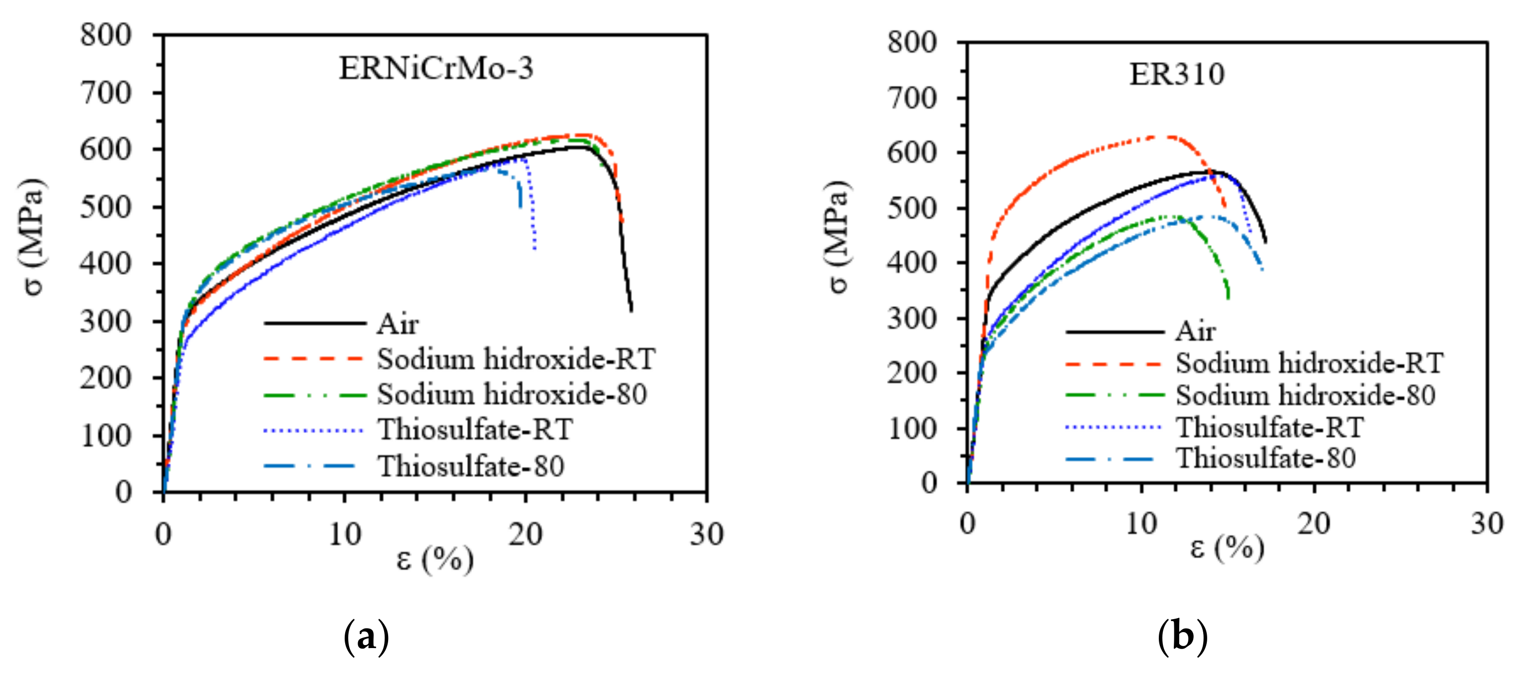
3.2. SSRT Analysis at Ecorr

The engineering stress–strain profiles obtained from the SSR tests in the two welding conditions are shown in Figure 7a,b for the ERNiCrMo-3 and ER310 fillers, respectively. Immediately, it can be seen from the σ–ε curves plotted in Figure 7 that the mechanical properties of the welded joints changed when the welded specimens were immersed in NaOH or Na2S2O3 at two different temperatures. These changes were reflected in the ductility, ultimate tensile strength (UTS), and yield strength (σ0.2%) and these changes involved an increase or decrease in some of these properties, these being more notable in the ER310 welds. The UTS of the ERNiCrMo-3 weld in the 5 M NaOH solution showed a moderate increase with respect to the UTS obtained in air. It could be observed that the sodium thiosulfate was more corrosive to the ERNiCrMo-3 welded joints compared to the sodium hydroxide (see Figure 7a). Meanwhile, the ER310 weld exhibited sensitivity in the two electrolytes (see Figure 7b). In Figure 7a,b, it can be seen that the plastic zone at room temperature (RT) showed a similar behavior in the two electrolytes whereas when the temperature increased, this behavior changed (also in both electrolytes). A plateau that formed in the plastic zone was observed at RT; this effect may be attributed to the combination of the electrolyte with the movement of dislocations that are probably controlled by slip bands at RT during strain. In contrast, when the temperature increases, this movement will speed up, breaking through the slip bands and secondary phases. If this mechanism takes place, the plastic zone will exhibit a concave shape [43]. As was previously observed, the mechanical behavior of the IN600 joints with the ERNiCrMo-3 and ER310 filler materials presented almost the same yield stress [42], but in the low strain rate test, this similarity no longer manifested.
Table 2 shows the mechanical properties obtained and the susceptibility to stress corrosion cracking, ISCC, as calculated from the data of the curves plotted in Figure 7. According to these results, it can be observed that the susceptibility to SCC increases when the test temperature is higher. The ISCC was found to be quite discrete when the weld specimens were tested in the 5 M NaOH solution. In this media, there was only a 3% reduction in the ISCC. This may have been caused by the formation of Cr carbides, which positively influenced the SCC resistance [27,28]. In this regard, the aging of the IN600 alloy might not be a concern in this environment. It has been said that the increase in the number of dislocations may reduce the possibility of SCC [44]. Dislocations and stacking faults are the consequence of stress. On the other hand, the Iδ was reduced between 12 and 25% for the ER310 weld in NaOH and the ERNiCrMo-3 weld in Na2S2O3, which means that the stainless steel was more susceptible to experience damage in caustic alkali solutions but less susceptible to sulfide containing solutions, where the opposite was true for the nickel-based alloys. It can be concluded that the electrolyte caused the welded samples to lose these mechanical properties. In addition, the positive IFRAG indicates that the cross section of the specimen in the test solution showed less reduction in area compared to the inert medium, indicating that the material was to some extent embrittled in the solution. When the value of this index is very small (<0.01), it indicates that the material did not experienced embrittlement in the medium, as observed in the NaOH for the ER310 weld.

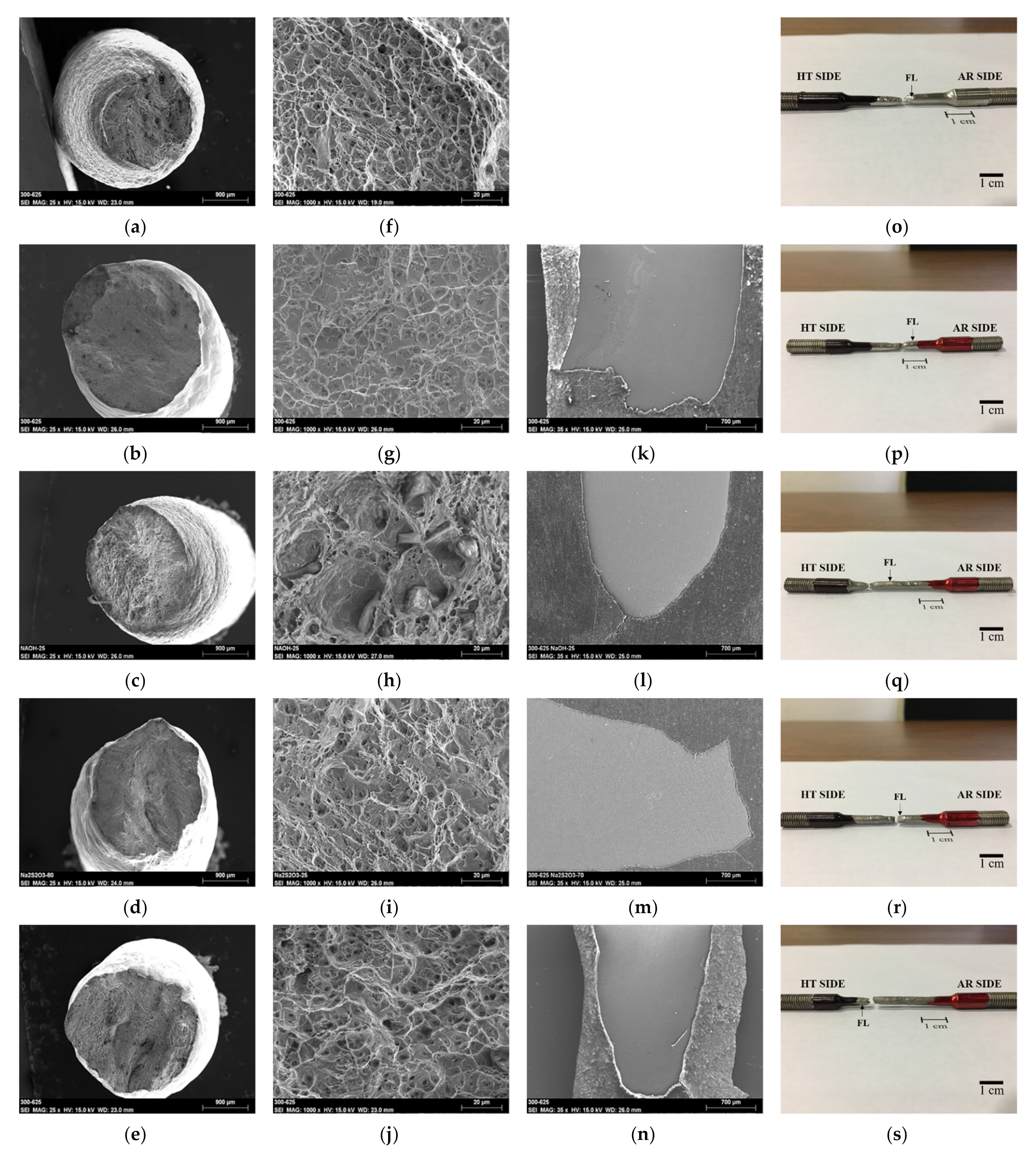
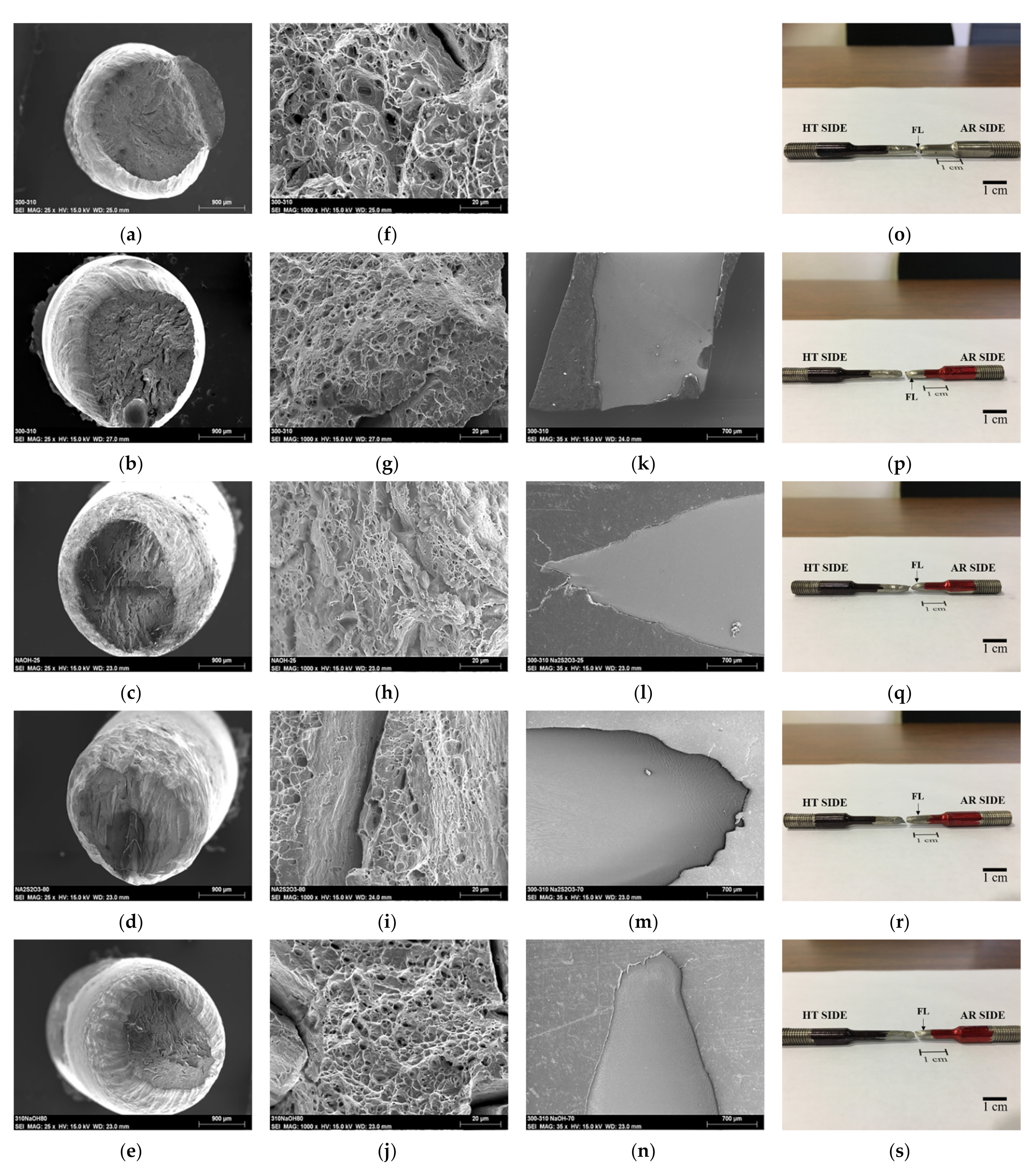
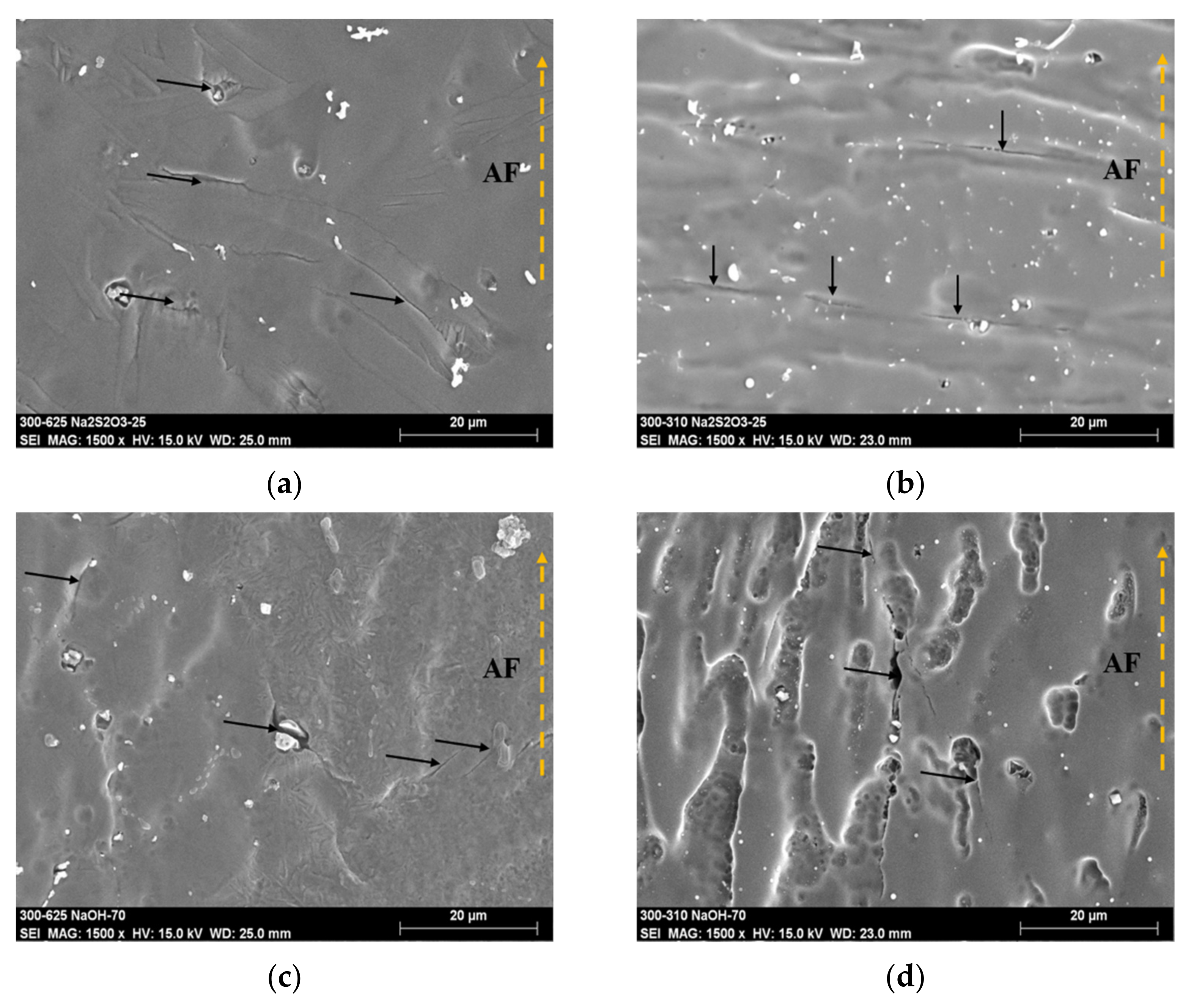
3.3. Surface Fracture Analysis after SSRT

The fracture features of each broken sample can be observed in the SEM. Figure 8 and Figure 9 are images captured in secondary electron mode in different directions of the fractured specimens. The top view of the crack (Figure 8a–e and Figure 9a–e, left column of each arrangement) was used to measure the area reduction to obtain the IFRAG. The lateral view (Figure 8k–n and Figure 9k–n) was used to determine whether or not secondary cracks were generated in the gauge section as a result of the stress induced under the influence of the electrolyte. The macrographs of the broken specimens (Figure 8o–s and Figure 9o–s) are shown to identify the place where the welded joint failed. Figure 8 shows the fracture details of the ERNiCrMo-3 welded joint in the control and corrosive environments. As can be observed, almost all of the samples fractured in the NiCrMo-3 WM and showed the formation of dimples with the characteristic cup and cone failure. The transgranular fracture mode was observed and the cracks propagated in different directions. The propagation route of the crack is dictated in the weld metal to some extent by the competitive columnar growth of the grains during solidification of the weld bead. It has been reported that Ni-based alloys preferentially show an intergranular mode of fracture in the SCC tests [45]. In Figure 8k, it is clear that the specimen did not fail with the cup and cone shape formation, but that the failure occurred somehow perpendicular to the axial force and the density of the dimples was reduced but increased in its size (Figure 8g) with respect to the reference sample. Lu and co-workers [19] observed that a higher resistance or lower crack propagation speed was obtained in specimens that were prepared and tested in the longitudinal direction of the dendritic growth. Due to the existence of preferential oxidation, chemical composition, and the concentration of defects in the transversal direction, the SCC susceptibility increased. In this weldment in the thiosulfate electrolyte, the failure occurred most closely on the AR side, as shown in Figure 8p, because the dendrite size was much larger and less precipitation was found, which allowed for the fracture to propagate faster compared to the HT side (as can be seen in Figure 2). Additionally, this could be due to the formation of islands in the WM, as can be seen in Figure 3a.
The fracture of the ER310 samples are shown in the set of Images shown in Figure 9. Each medium showed a transgranular (in the dendrites growth) quasi-cleavage failure mode characterized with some dimples and several micro cracks, as could be seen even in the control atmosphere. The transgranular feature was clearly observed with the increase in the electrolyte temperature. The ER310 filler material is an austenitic stainless steel and sometimes is prone to the formation of martensite as a result of plastic deformation. The features in the rupture zone were similar to the observed in the high strength low alloy steels (HSLA) when they absorbed hydrogen+ [46]. The martensitic structure is very prone to embrittlement by the hydrogen absorption [47,48]. It might be inferred that the nucleation of micro cracks and the loss of plasticity are due the diffusion of monoatomic H in the ER310 weld metal in both electrolytes (NaOH and Na2S2O3) due to the martensitic transformation. It was noted in the images of Figure 9o–s that the failure consistently occurred near the fusion line (FL) on the HT side, where the microstructure characteristics such as the dendrite size was smaller than on the AR side (as was observed in Figure 3). Better SCC resistance was expected on the HT side due the quantity of Cr carbides observed, which arrested the crack propagation, but the high local energy from the effect of temperature, quenching, and tensional residual stresses produced the failure in this zone. It has often been reported that the formation of carbides may enhance the resistance to SCC [28]. It could be observed that the micro hollows formed in the fracture surface would be higher in mean size as the susceptibility to SCC increases (see Figure 9f–j), similar to the features found in Figure 8h. Furthermore, some particles inside the hollows were observed and acted as tri-axial stress concentrators, where they aided in the bifurcation and propagation of the stress corrosion cracks more quickly.
In the analyzed samples, as shown in Figure 8o–s and Figure 9o–s, at near neutral pH values, the HT side tended to be the origin of the failure, which was due the high quantity of storage energy due to the HT followed by quenching. Somehow, on the AR side, the entrapment of the base metal in the weld metal did not alter the mechanical properties of the welds, as previously reported from the plain tensile tests of the welded joints [42]. Furthermore, a similar mechanical behavior of the monolithic heat treated IN600 was observed compared to the as-received plates [42], even when the effect of solid solution strengthening decreased by the formation of Cr-carbides as a result of the extended holding at 700 °C.
Figure 10 shows the formation of secondary cracks near the fracture surface in two different electrolytes at two temperatures. It can be seen from Figure 10a,b that compared with the cracks observed in the 310 stainless steel WM, the formation of secondary cracks in the Ni-based (NiCrMo-3) WM showed that the size of the crack was at least 20 μm and the depth was significantly higher. It can be concluded that Ni-based materials are more prone to sulfide cracking than stainless steels. This result is very consistent with the findings observed in Table 2, where Na2S2O3 was more sensitive to SCC for the ERNiCrMo-3 welded joint. Tsai and co-workers [49] found that for IN600 in both AR and HT conditions, the formation of cracks was likely to occur, even with low quantities of Na2S2O3 and no potential applied during the SCC test (at Ecorr). The time needed for crack initiation in the conditions analyzed was approximately 5 h. On the other hand, from Figure 10c,d the secondary crack formation in NaOH at 80 °C prevailed for the stainless steel WM. In this instance, the cracks nucleated and grew principally in the interdendritic zones, while the cracks in the ERNiCrMo-3 welded joint passed through secondary phases. The SCC analysis of duplex stainless steel showed that the austenite was more susceptible to the formation and propagation of cracks when the material was exposed to caustic environments [50]. It is believed that the sensitivity of SCC to a NaOH environment is due to the Na+ ions in part of the electrolyte [30]. The possibility of ferrite formation in the ER310 weld metal is due to the dilution percentage obtained in the joint. If this formation is possible, it is well-known that ferrite is deformed by deformation slip of the slip system, and austenite can be deformed by dislocation slip, twin formation, and martensite transformation, depending on its stacking fault energy (SFE). Cr, Mn, Si, and N reduce the SFE, while Ni and C increase it [51].

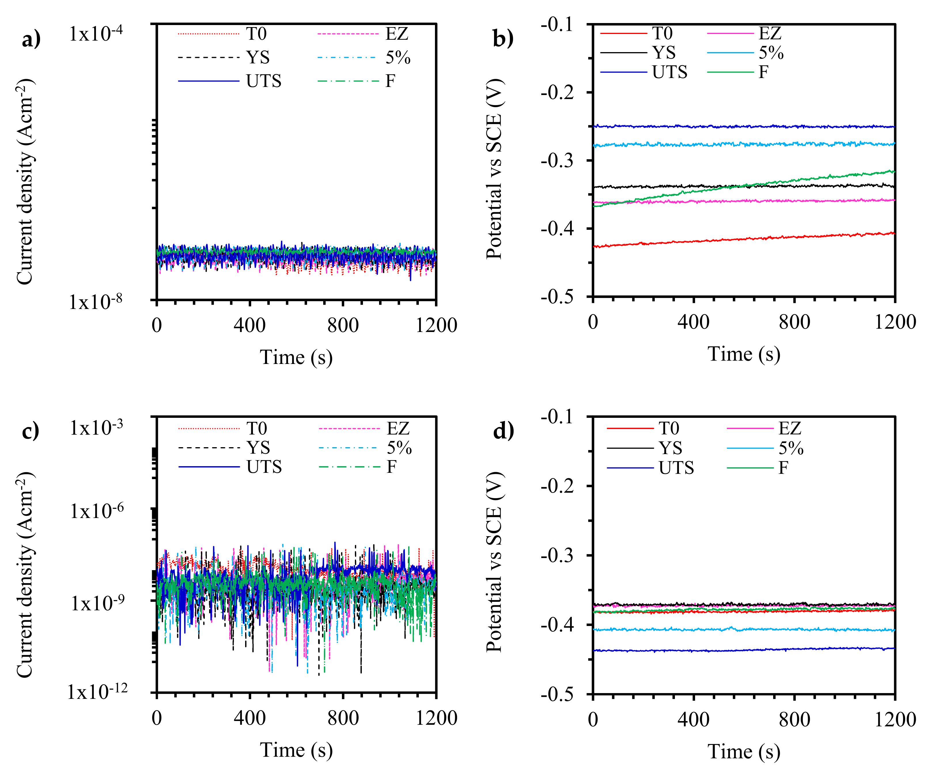
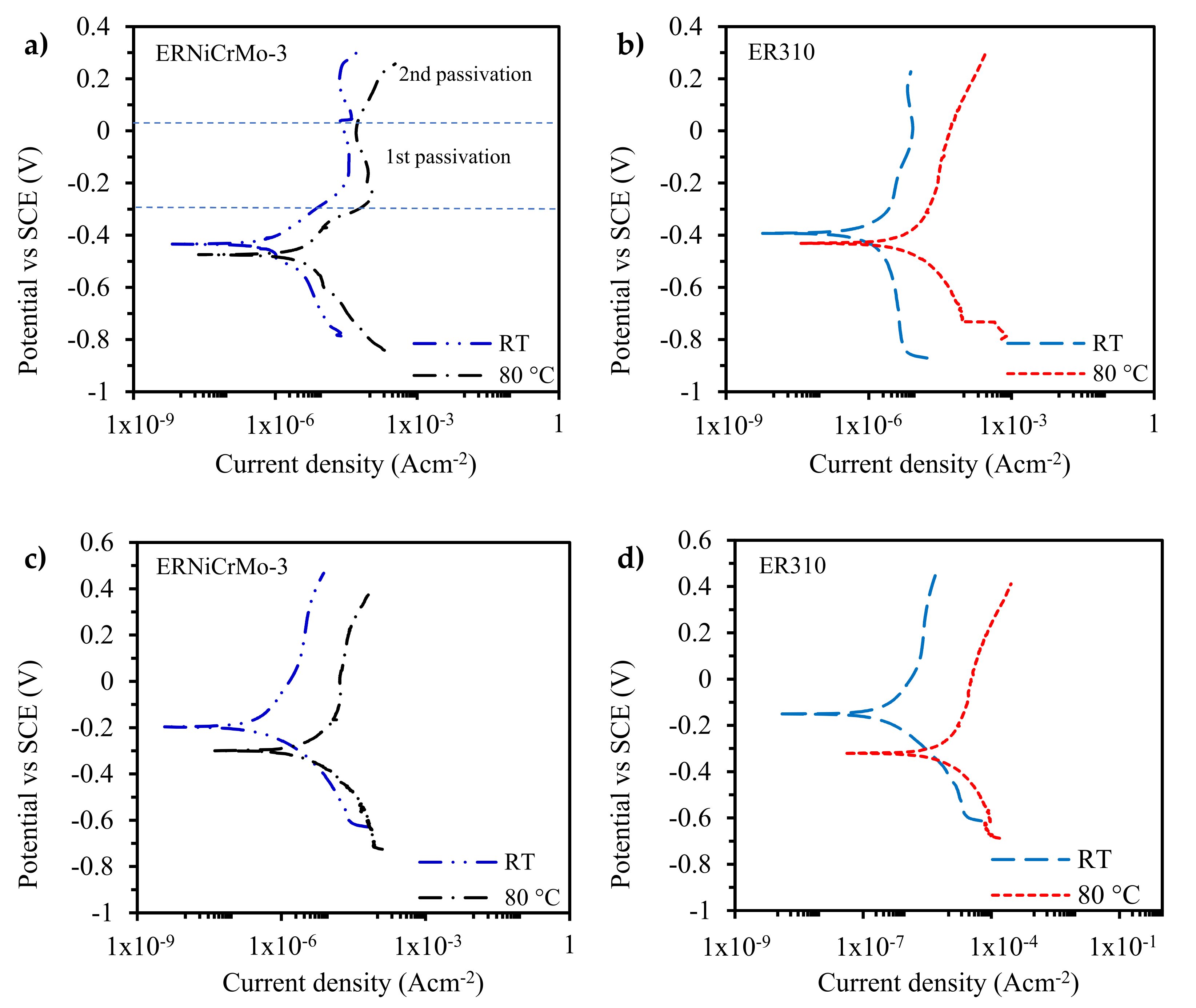
3.4. Electrochemical Noise (EN) and Polarization Scan

Figure 11 and Figure 12 display the fluctuation of the current density and potential during the SSRT in the two electrolytes used to promote the corrosion process. In Figure 11a–c a–c and Figure 12a–c, observations of the current fluctuation signal showed that the current density rapidly increased to an anodic value in the elastic zone, but when the σy was overcome, the anodic current only exhibited a lower change. In the failure time, the anodic currents observed in the previous stage newly changed to a cathodic value (i.e., the current density decreased), and at the same time, the potential changed to less noble when the failure was completed (see Figure 11b,d and Figure 12b,d). On the other hand, for the potential changes observed in Figure 11b,d and Figure 12b,d, Zhiming et al. [52] described that the potential transients were associated with the sudden rupture of the passive film on the strained sample, and then the sample gradually re-passivated in the film fracture zone. In Figure 11c, higher fluctuations could be observed in the Na2S2O3 solution at 80 °C during the SSRT, so these fluctuations, referred to as over position events, were the anodic and cathodic currents that suddenly changed almost at the same time [30]. This was due to the high energy from the strain and corrosion processes when the temperature increased. Another characteristic where the noise behaved with greater fluctuations, as can be seen in Figure 12, was because the materials failed, showing a brittle characteristic, as was the case for the ER310 welded joint (see Figure 8 and Figure 9).
Two different media were used to perform the corrosion stress cracking (CSC) tests; for this purpose, potentiodynamic polarization tests were performed on the NaOH and Na2S2O3 electrolytes at room temperature and at 80 °C on the ERNiCrMo-3 and ER310 welds. Figure 13 displays the polarization curves of the two weldments in Na2S2O3 and NaOH. The ERNiCrMo-3 weld showed an active region up to potentials of −0.15 V vs. SCE in the 5 M NaOH electrolyte, and after this potential, a passive region (Figure 13a) was seen up to E = 0 V vs. SCE and then a trans-passive region was formed. The welds showed passivity in the sodium thiosulfate and sodium hydroxide solutions and pitting corrosion was not present during the anodic scanning. When the temperature of the electrolyte was 80 °C, both the anodic and the cathodic reactions presented higher current densities than those at RT, and the corrosion potential was displaced to more active values. The effect was more severe in the welds made with the ER310 than with the ERNiCrMo-3 filler metal. However, the anodic and cathodic kinetics maintained the same tendency (slope) at RT and at 80 °C for both the filler metals and the electrolytes tested. The anodic polarization did not induce localized corrosion. The results are in good agreement with the observations in the SSRT results (Table 2). According to the results of the EN, the corrosion potential during the SSRT was anodic, which indicates that the passive film formed in the surface of the welds was stable, maintaining the passive state that was seen in the polarization scanning. Thus, it might be concluded that if the passive film breaks, it will be rapidly regenerated. Meanwhile, the current density oscillations could be due to the breaking and regeneration of the passive film, which entered the trans passive dissolution zone (as seen in Figure 13a). In the NaOH solution, the trans passivity was caused by the breaking of the film in the mode of metal vacancy [53]. The increase in the output current in NaOH for the ERNiCrMo-3 weld was less pronounced than in the ER310 weld, and this difference was almost at 1 order of magnitude. It was observed that the results of the traces shown in Figure 13a,b were consistent with the results obtained in the SSR tests. In Figure 13c,d, it was observed that the susceptibility in the ER310 weld was lower than in the ERNiCrMo-3 weld. It has been reported in the literature that stainless steel shows a susceptibility to SCC when it is in contact with NaOH [50], and conversely, the Ni-based alloys showed a susceptibility to SCC in sulfide environments [54].
Figure 14 shows the localization index (LI) obtained in thiosulfate and caustic sodium for the two weldments. As can be seen in Figure 14a, during the SSR tests, the LI was very close to zero, but a change in the corrosion behavior was evident. For example, the LI in Na2S2O3 increased, and the corrosion behavior changed from uniform corrosion to mixed corrosion. In the counterpart, the LI in caustic sodium at 80 °C showed localized corrosion, since LI is directly dependent on the current density. According to the results of the polarization curves (Figure 13), the corrosion rate increased with the increment in temperature. This effect is related to the reduction observed for the index mechanical properties of the SSRT results (Table 2). This may be explained by the formation of metastable pits (passive with the time) during SSRT. The sample showed a similar behavior of LI during the SSRT when it was immersed in NaOH and Na2S2O3, as can be seen in Figure 14a. Conversely, in Figure 14b, with an increase in the solution temperature, the corrosion mode observed in the LI results shifted from localized corrosion to mixed corrosion. A remarkable observation in Figure 14 was that when the samples were in the plastic zone, they suffered a change in the LI value, but in this plastic zone, the LI behaved linearly or the slope was ~0. Another finding was that when a material showed higher susceptibility (see Iδ in Table 2) in a media, the LI tended to have a value of zero or the corrosion type was uniform corrosion.

4. Conclusions

The effects of sodium thiosulfate and sodium hydroxide to the susceptibility to SCC using the SSR technique in the welded joints of IN600 in the AR condition to IN600 HT using two different filler metals were investigated. From the study, the most relevant conclusions are as follows.
The microstructure in the weldments showed some features that were differentiated by the chemical composition, cooling rate, and the formation of secondary phases (i.e., when the ERNiCrMo-3 filler metal was employed, the main secondary phases observed were carbides, nitrates, and Laves phase). The segregation of Nb and Mo promoted the formation of Laves phase; moreover, the solidification mode changed along the WM in the ERNiCrMo-3 weld. On the other hand, mainly oxides were observed as secondary phases in the WM of the ER310 filler.
According to the plasticity lost index (Iδ) results, the plastic elongation of the ER310 weld was reduced by 12% when the NaOH solution was used, while the plastic elongation was reduced by 25% when the ERNiCrMo-3 weld was immersed in Na2S2O3. A reduction in this index may mean that stainless steel is more susceptible to damage in caustic solutions, but less sensitive to sulfide-containing solutions, while nickel-based alloys are very sensitive to Na2S2O3.
In the SSRT fracture analysis, it was observed that the dendrite size influenced the crack propagation due the lower barriers obtained in the larger dendrite size. According to the potentiodynamic polarization tests in NaOH, the welds presented transpassive dissolution at high anodic potentials.
High fluctuations were observed in both solutions during the SSRT. This phenomenon is believed to occur due the high energy from the strain and corrosion process when the strain, temperature, and corrosion process increased. In addition, the EN showed that when the noise behaved with greater fluctuations, the weldment displayed a brittle failure characteristic, as was the case in the ER310 joint. Even when the values of the current density were ~1 × 10⁻⁹, the joint showed SCC susceptibility, but in some cases, the Na and sulfide ions affected the ERNiCrMo-3 welded joint more than that of the ER310 in the global Iscc but not in the Iδ.
The LI showed a change in the corrosion process during the SSRT when the ERNiCrMo-3 sample was immersed in NaOH, where the LI changed from 0.002 to 0.14 when the temperature was decreased. In contrast, in Na2S2O3, the LI increased from 0.003 to 0.02 when the temperature of the solution was increased. According to the potential transients, the welds were located in the SCC zone because the values were higher than the potential corrosion measured in the polarization curves as well as proximally to the passivation range.

Author Contributions

H.G.-B. performed most of the experimental work and wrote the manuscript; V.H.L.-M. conceived the study, obtained funding for the project, wrote, and edited the manuscript; A.C. performed the SSRT tests and noise measurements; F.F.C.-L. assisted in the welding and critically reviewed the manuscript; R.G.-H. supervised the welding process, microstructural characterization, and reviewed the manuscript; J.A.G.-S. analyzed the corrosion results, reviewed, and edited the document; E.C. performed the experimental work and aided in writing up the manuscript. All authors have read and agreed to the published version of the manuscript.

Funding

Coordinación de la Investigación Científica (CIC) of the UMSNH.

Institutional Review Board Statement

Not applicable.

Informed Consent Statement

Not applicable.

Data Availability Statement

The data presented in this study are available on request from the corresponding author.

Acknowledgments

The authors thank CONACyT for proving a scholarship to H.G.-B. during his doctorate stay and the aid of the SEM technicians Antonio Rodriguez and Victor Sayil López. The authors are also grateful to the Mexican Petroleum Institute (IMP) for supporting this project by making the MCERT machine available.

Conflicts of Interest

The authors declare no conflict of interest.

References

  1. Al-Rubaie, K.S.; Godefroid, L.B.; Lopes, J.A. Statistical modeling of fatigue crack growth rate in Inconel alloy 600. Int. J. Fatigue 2007, 29, 931–940. [Google Scholar] [CrossRef]
  2. Chandrasekar, G.; Kailasanathan, C.; Verma, D.K. Investigation on un-peened and laser shock peened weldment of Inconel 600 fabricated by ATIG welding process. Mater. Sci. Eng. A 2017, 690, 405–417. [Google Scholar] [CrossRef]
  3. Kwon, J.-D.; Park, D.-K.; Woo, S.-W.; Yoon, D.-H.; Chung, I. A study on fretting fatigue life for the Inconel alloy 600 at high temperature. Nucl. Eng. Des. 2010, 240, 2521–2527. [Google Scholar] [CrossRef]
  4. Ru, X.; Staehle, R.W. Historical Experience Providing Bases for Predicting Corrosion and Stress Corrosion in Emerging Supercritical Water Nuclear Technology: Part 1—Review. Corrosion 2013, 69, 211–229. [Google Scholar] [CrossRef]
  5. Zhang, H.; Lu, Y.; Ma, M.; Li, J. Effect of precipitated carbides on the fretting wear behavior of Inconel 600 alloy. Wear 2014, 315, 58–67. [Google Scholar] [CrossRef]
  6. Lim, Y.S.; Kim, J.S.; Kim, H.P.; Cho, H.D. The effect of grain boundary misorientation on the intergranular M23C6 carbide precipitation in thermally treated Alloy 690. J. Nucl. Mater. 2004, 335, 108–114. [Google Scholar] [CrossRef]
  7. Abraham, G.J.; Bhambroo, R.; Kain, V.; Dey, G.; Raja, V. Intergranular Corrosion Susceptibility of Alloy 600 after Autogenous Tungsten Inert Gas and Laser Beam Welding using Electrochemical Technique. High Temp. Mater. Processes 2014, 33, 137–146. [Google Scholar] [CrossRef]
  8. Yoo, S.C.; Choi, K.J.; Kim, T.; Kim, S.H.; Kim, J.Y.; Kim, J.H. Microstructural evolution and stress-corrosion-cracking behavior of thermally aged Ni-Cr-Fe alloy. Corros. Sci. 2016, 111, 39–51. [Google Scholar] [CrossRef]
  9. das Neves, M.D.M.; Lotto, A.; Berretta, J.R.; Rossi, W.D.; Júnior, N.D.V. Microstructure development in Nd:YAG laser welding of AISI 304 and Inconel 600. Weld. Int. 2010, 24, 739–748. [Google Scholar] [CrossRef]
  10. Herrera-Chavez, L.Y.; Ruiz, A.; López-Morelos, V.H.; Rubio-González, C. Microstructural characterization and mechanical response of Inconel 600 welded joint. Mater. Charact. 2019, 157, 109882. [Google Scholar] [CrossRef]
  11. Lim, Y.S.; Kim, H.P.; Cho, H.D.; Lee, H.H. Microscopic examination of an Alloy 600/182 weld. Mater. Charact. 2009, 60, 1496–1506. [Google Scholar] [CrossRef]
  12. Łyczkowska, K.; Michalska, J. Studies on the Corrosion Resistance of Laser-Welded Inconel 600 and Inconel 625 Nickel-Based Superalloys. Arch. Metall. Mater. 2017, 62, 653–656. [Google Scholar] [CrossRef] [Green Version]
  13. Bhaduri, A.; Rai, S.; Gill, T.; Sujith, S.; Jayakumar, T. Evaluation of repair welding procedures for 2.25 Cr–1Mo and 9Cr–1Mo steel welds. Sci. Technol. Weld. Join. 2001, 6, 89–93. [Google Scholar] [CrossRef]
  14. Pandey, C. Mechanical and Metallurgical Characterization of Dissimilar P92/SS304 L Welded Joints Under Varying Heat Treatment Regimes. Metall. Mater. Trans. A 2020, 51, 2126–2142. [Google Scholar] [CrossRef]
  15. Shi, S.; Lippold, J.; Ramirez, J. Hot ductility behavior and repair weldability of service-aged, heat-resistant stainless steel castings. Weld. J. 2010, 89, 210–217. [Google Scholar]
  16. Wang, X.; Li, Y.; Li, H.; Lin, S.; Ren, Y. Effect of long-term aging on the microstructure and mechanical properties of T23 steel weld metal without post-weld heat treatment. J. Mater. Process. Technol. 2018, 252, 618–627. [Google Scholar] [CrossRef]
  17. Faichuk, M.G.; Ramamurthy, S.; Lau, W.M. Electrochemical behaviour of Alloy 600 tubing in thiosulphate solution. Corros. Sci. 2011, 53, 1383–1393. [Google Scholar] [CrossRef]
  18. Lu, W.-F.; Huang, J.-Y.; Yung, T.-Y.; Chen, T.-C.; Tsai, K.-C. Effects of dendrite axis and fusion boundary on stress corrosion cracking of ER 308 L/SS 304L welds in a high-temperature water environment. Int. J. Press. Vessel. Pip. 2020, 179, 103940. [Google Scholar] [CrossRef]
  19. Lu, Z.; Chen, J.; Shoji, T.; Meng, F. Dependence of crack growth kinetics on dendrite orientation and water chemistry for Alloy 182 weld metal in high-temperature water. J. Nucl. Mater. 2015, 458, 253–263. [Google Scholar] [CrossRef]
  20. Contreras, A.; Salazar, M.; Carmona, A.; Galván-Martínez, R. Electrochemical Noise for Detection of Stress Corrosion Cracking of Low Carbon Steel Exposed to Synthetic Soil Solution. Mater. Res. 2017, 20, 1201–1210. [Google Scholar] [CrossRef] [Green Version]
  21. Amaro Vicente, T.; Oliveira, L.A.; Correa, E.O.; Barbosa, R.P.; Macanhan, V.B.P.; Alcântara, N.G.D. Stress Corrosion Cracking Behaviour of Dissimilar Welding of AISI 310S Austenitic Stainless Steel to 2304 Duplex Stainless Steel. Metals 2018, 8, 195. [Google Scholar] [CrossRef] [Green Version]
  22. Dong, L.; Peng, Q.; Han, E.-H.; Ke, W.; Wang, L. Stress corrosion cracking in the heat affected zone of a stainless steel 308L-316L weld joint in primary water. Corros. Sci. 2016, 107, 172–181. [Google Scholar] [CrossRef]
  23. Han, J.; da Silva, A.K.; Ponge, D.; Raabe, D.; Lee, S.-M.; Lee, Y.-K.; Lee, S.-I.; Hwang, B. The effects of prior austenite grain boundaries and microstructural morphology on the impact toughness of intercritically annealed medium Mn steel. Acta Mater. 2017, 122, 199–206. [Google Scholar] [CrossRef]
  24. Nishikawa, S.; Horii, Y.; Ikeuchi, K. Effect of phosphorus content on stress corrosion cracking susceptibility of shielded metal arc weld metals for 600 type alloy in high temperature pressurised pure water. Weld. Int. 2013, 27, 747–757. [Google Scholar] [CrossRef]
  25. Wang, J.D.; Gan, D. Effects of grain boundary carbides on the mechanical properties of Inconel 600. Mater. Chem. Phys. 2001, 70, 124–128. [Google Scholar] [CrossRef]
  26. Kikuchi, H.; Takahashi, H.; Yanagiwara, H.; Murakami, T. Relationship between ferromagnetic properties and grain size of Inconel alloy 600. J. Magn. Magn. Mater. 2015, 381, 56–64. [Google Scholar] [CrossRef]
  27. Mostafanejad, A.; Iranmanesh, M.; Zarebidaki, A. An experimental study on stress corrosion behavior of A131/A and A131/AH32 low carbon steels in simulated seawater. Ocean. Eng. 2019, 188, 106204. [Google Scholar] [CrossRef]
  28. Lippold, J.C.; Kiser, S.D.; DuPont, J.N. Welding Metallurgy and Weldability of Nickel-Base Alloys; John Wiley & Sons: New York, NY, USA, 2011. [Google Scholar]
  29. Chandrasekar, G.; Kailasanathan, C.; Vasundara, M. Investigation on un-peened and laser shock peened dissimilar weldments of Inconel 600 and AISI 316L fabricated using activated-TIG welding technique. J. Manuf. Process. 2018, 35, 466–478. [Google Scholar] [CrossRef]
  30. Montoya-Rangel, M.; Garza-Montes de Oca, N.; Gaona-Tiburcio, C.; Colás, R.; Cabral-Miramontes, J.; Nieves-Mendoza, D.; Maldonado-Bandala, E.; Chacón-Nava, J.; Almeraya-Calderón, F.J.M. Electrochemical noise measurements of advanced high-strength steels in different solutions. Metals 2020, 10, 1232. [Google Scholar] [CrossRef]
  31. Kourdani, A.; Derakhshandeh-Haghighi, R. Evaluating the Properties of Dissimilar Metal Welding Between Inconel 625 and 316L Stainless Steel by Applying Different Welding Methods and Consumables. Metall. Mater. Trans. A 2018, 49, 1231–1243. [Google Scholar] [CrossRef]
  32. Lee, H.T.; Jeng, S.L.; Kuo, T.Y. The microstructure and fracture behavior of the dissimilar alloy 690-SUS 304L joint with various Nb addition. Metall. Mater. Trans. A 2003, 34, 1097–1105. [Google Scholar] [CrossRef]
  33. Ruiz-Vela, J.I.; Montes-Rodríguez, J.J.; Rodríguez-Morales, E.; Toscano-Giles, J.A. Effect of cold metal transfer and gas tungsten arc welding processes on the metallurgical and mechanical properties of Inconel® 625 weldings. Weld. World 2019, 63, 459–479. [Google Scholar] [CrossRef]
  34. Silva, C.C.; Miranda, H.C.D.; Motta, M.F.; Farias, J.P.; Afonso, C.R.M.; Ramirez, A.J. New insight on the solidification path of an alloy 625 weld overlay. J. Mater. Res. Technol. 2013, 2, 228–237. [Google Scholar] [CrossRef] [Green Version]
  35. Shah Hosseini, H.; Shamanian, M.; Kermanpur, A. Characterization of microstructures and mechanical properties of Inconel 617/310 stainless steel dissimilar welds. Mater. Charact. 2011, 62, 425–431. [Google Scholar] [CrossRef]
  36. Mortezaie, A.; Shamanian, M. An assessment of microstructure, mechanical properties and corrosion resistance of dissimilar welds between Inconel 718 and 310S austenitic stainless steel. Int. J. Press. Vessel. Pip. 2014, 116, 37–46. [Google Scholar] [CrossRef]
  37. Bogaard, R.H. Thermal Conductivity of Selected Stainless Steels. In Thermal Conductivity 18; Ashworth, T., Smith, D.R., Eds.; Springer: Boston, MA, USA, 1985; pp. 175–185. [Google Scholar]
  38. Farias, F.W.C.; Payão Filho, J.D.C.; da Silva Júnior, D.A.; de Moura, R.N.; Rios, M.C.G. Microstructural characterization of Ni-based superalloy 625 clad welded on a 9% Ni steel pipe by plasma powder transferred arc. Surf. Coat. Technol. 2019, 374, 1024–1037. [Google Scholar] [CrossRef]
  39. DuPont, J.N. Solidification of an alloy 625 weld overlay. Metall. Mater. Trans. A 1996, 27, 3612–3620. [Google Scholar] [CrossRef]
  40. Silva, C.C.; de Albuquerque, V.H.C.; Miná, E.M.; Moura, E.P.; Tavares, J.M.R.S. Mechanical Properties and Microstructural Characterization of Aged Nickel-based Alloy 625 Weld Metal. Metall. Mater. Trans. A 2018, 49, 1653–1673. [Google Scholar] [CrossRef] [Green Version]
  41. Cortés-Cervantes, I.S.; López-Morelos, V.H.; Miyashita, Y.; García-Hernández, R.; Ruiz-Marines, A.; Garcia-Renteria, M.A. Fatigue resistance of AL6XN super-austenitic stainless steel welded with electromagnetic interaction of low intensity during GMAW. Int. J. Adv. Manuf. Technol. 2018, 99, 2849–2862. [Google Scholar] [CrossRef]
  42. Granados-Becerra, H.; López-Morelos, V.H.; Ruiz, A.; García-Hernández, R.; Curiel-López, F.F.; Barajas-Alvarez, M.R.J.M.; International, M. Ramberg–Osgood Stress–Strain Analysis of the Effects of Aging Treatment and Welding on IN600 with a Three-Stage Strain Hardening Behavior. Met. Mater. Int. 2021, 28, 1328–1339. [Google Scholar] [CrossRef]
  43. Bai, G.; Li, J.; Hu, R.; Tang, Z.; Xue, X.; Fu, H. Effect of temperature on tensile behavior of Ni–Cr–W based superalloy. Mater. Sci. Eng. A 2011, 528, 1974–1978. [Google Scholar] [CrossRef]
  44. Hur, D.H.; Lee, D.H. Effect of solid solution carbon on stress corrosion cracking of Alloy 600 in a primary water at 360 °C. Mater. Sci. Eng. A 2014, 603, 129–133. [Google Scholar] [CrossRef]
  45. Brown, C.; Mills, W.J.C. Effect of water on mechanical properties and stress corrosion behavior of alloy 600, alloy 690, EN82H welds, and EN52 welds. Corrosion 1999, 55, 173–186. [Google Scholar] [CrossRef]
  46. Zhou, C.; Huang, Q.; Guo, Q.; Zheng, J.; Chen, X.; Zhu, J.; Zhang, L. Sulphide stress cracking behaviour of the dissimilar metal welded joint of X60 pipeline steel and Inconel 625 alloy. Corros. Sci. 2016, 110, 242–252. [Google Scholar] [CrossRef]
  47. López, F.F.; García, R.; López, V.; Garcia, M.; Contreras, A. The Effect of Applying Magnetic Fields During Welding AISI- 304 Stainless Steel on Stress Corrosion Cracking. Int. J. Electrochem. Sci. 2021, 16, 210338. [Google Scholar]
  48. Matsunaga, H.; Yoshikawa, M.; Kondo, R.; Yamabe, J.; Matsuoka, S. Slow strain rate tensile and fatigue properties of Cr–Mo and carbon steels in a 115 MPa hydrogen gas atmosphere. Int. J. Hydrogen Energy 2015, 40, 5739–5748. [Google Scholar] [CrossRef]
  49. Tsai, W.-T.; Chang, C.-S.; Lee, J.-T.J.C. Effects of shot peening on corrosion and stress corrosion cracking behaviors of sensitized alloy 600 in thiosulfate solution. Corrosion 1994, 50, 98–105. [Google Scholar] [CrossRef]
  50. Bhattacharya, A.; Singh, P.M. Stress corrosion cracking of welded 2205 duplex stainless steel in sulfide-containing caustic solution. J. Fail. Anal. Prev. 2007, 7, 371–377. [Google Scholar] [CrossRef]
  51. Claeys, L.; Depover, T.; De Graeve, I.; Verbeken, K. First observation by EBSD of martensitic transformations due to hydrogen presence during straining of duplex stainless steel. Mater. Charact. 2019, 156, 109843. [Google Scholar] [CrossRef]
  52. Shi, Z.; Song, G.; Cao, C.-N.; Lin, H.; Lu, M.J.E.A. Electrochemical potential noise of 321 stainless steel stressed under constant strain rate testing conditions. Electrochim. Acta 2007, 52, 2123–2133. [Google Scholar] [CrossRef]
  53. Sikora, E.; Macdonald, D.D.J.E.A. Nature of the passive film on nickel. Electrochim. Acta 2002, 48, 69–77. [Google Scholar] [CrossRef]
  54. Espinoza-Medina, M.; Martinez-Villafane, A.; Salinas-Bravo, V.; Gonzalez-Rodriguez, J.J.C. Predicting susceptibility to intergranular stress corrosion cracking of Alloy 690. Corrosion 2000, 56, NACE-00111133. [Google Scholar]
Figure 1. (a) Single-V groove joint design (b) schematic representation of the specimens machined for SCC and the (c) dimension and geometry of the SCC specimens. Dimensions in mm.
Metals 12 01112 g001aMetals 12 01112 g001b
Figure 2. Microstructure of IN600 (a,b) AR and (c,d) HT at 700 °C for 300 h.
Metals 12 01112 g002
Figure 3. (a) Macrograph of the welded joint obtained with the ERNiCrMo-3 filler and (bd) microstructural details as observed in the OM.
Metals 12 01112 g003
Figure 4. (a) Macrograph of the welded joint obtained with the ER310 filler and (bd) microstructural details as observed in the OM.
Metals 12 01112 g004aMetals 12 01112 g004b
Figure 5. (a) The SEM image at the weld metal with the ERNiCrMo-3 filler and (b) the results of the EDX dot chemical compositions of the points indicated in (a).
Metals 12 01112 g005
Figure 6. (a) The SEM image at the weld metal with the ER310 filler and (b) the results of the EDX dot chemical compositions of the points indicated in (a).
Metals 12 01112 g006
Figure 7. The stress–strain curves of the IN600 welds immersed in 0.1 M Na2S2O3 and 5M NaOH at Ecorr as tested at room temperature and 80 °C for (a) ERNiCrMo3 and (b) ER310 fillers.
Metals 12 01112 g007
Figure 8. The SEM characterization of the fractured specimens for the ERNiCrMo-3 welded joint in the inert and corrosive environments. (a,f,o) air; (b,g,k,p) Na2S2O3 at RT; (c,h,l,q) NaOH at RT; (d,i,m,r) Na2S2O3 at 80 °C, and (e,j,n,s) NaOH at 80 °C.
Metals 12 01112 g008
Figure 9. The SEM characterization of the fractured specimens for the ER310 welded joint in the inert and corrosive environments. (a,f,o) air; (b,g,k,p) Na2S2O3 at RT; (c,h,l,q) NaOH at 25 °C; (d,i,m,r) Na2S2O3 at 80 °C, and (e,j,n,s) NaOH at 80 °C.
Metals 12 01112 g009
Figure 10. The secondary cracking of IN600 welds after SSRTs in (a,b) Na2S2O3 at RT and (c,d) NaOH at 80 °C. AF = applied force direction, (a,c) corresponds to the ERNiCrMo-3 weld and (b,d) to the ER310 weld. Black arrows point to the secondary cracks.
Metals 12 01112 g010
Figure 11. The current and potential time series from the EN measurements for the ERNiCrMo-3 weld in Na2S2O3 (a,b) RT and (c,d) 80 °C.
Metals 12 01112 g011
Figure 12. The current and potential time series from the EN measurements for the ER310 weld in NaOH (a,b) RT and (c,d) 80 °C.
Metals 12 01112 g012
Figure 13. The polarization curves of the IN600 joints in (a,b) NaOH and (c,d) Na2S2O3.
Metals 12 01112 g013
Figure 14. The change in the LI through different conditions for the (a) ERNiCrMo-3 weld and (b) ER310 weld. LC: Localized corrosion, MC: Mixed corrosion.
Metals 12 01112 g014
Table 1. The chemical compositions of the IN600 plates and filler wires (wt.%).
CSiMnCrTiFeCuPSAlNiNbMo
IN600 OES0.0180.2190.19716.330.2679.1070.125<0.01-0.26473.47--
IN600 supplier0.020.190.216.410.259.110.130.006-0.273.09
ERNiCrMo-30.010.050.0522.06-0.921-0.0060.003-64.383.68.92
ER3100.10.451.726.0-51.020.1<0.02<0.01-20.5-0.1
Table 2. The mechanical properties of the welded joints obtained from the different SSR test conditions and estimated susceptibility indices to SCC. The red color denotes which electrolyte had more effect on the welds.
Weld
Filler
Environmentσy,0.2%
(MPa)
UTS
(MPa)
δ
(mm)
Plastic Elongation (%)Area Reduction (%)Time to Failure (h)ISCCIδ (%)IFRAG
ERNiCrMo-3Air292.98604.558.2724.7380.5995.62---
Na2S2O3 at RT250.02582.816.5519.39 50.6075.670.8020.741.54
NaOH at RT282.53625.478.0924.1970.7593.530.972.160.51
Na2S2O3 at 80 °C305.35565.206.3118.5464.3472.840.8323.700.84
NaOH at 80 °C292.51617.217.7323.0861.7989.370.936.480.97
ER 310 Air 340.28565.615.4915.9168.4463.38---
Na2S2O3 at RT262.00558.455.2115.1762.7260.020.925.230.18
NaOH at RT420.22629.494.7913.6269.7555.160.9812.86−0.04
Na2S2O3 at 80 °C230.18485.465.4316.0471.2462.640.941.13−0.09
NaOH at 80 °C232.49485.544.8114.0679.7155.410.8912.55−0.36
Publisher’s Note: MDPI stays neutral with regard to jurisdictional claims in published maps and institutional affiliations.

