Article

Numerical Investigation of Impact Behavior of Strut-Based Cellular Structures Designed by Spatial Voronoi Tessellation

1
School of Materials and Chemistry, University of Shanghai for Science and Technology, Shanghai 200082, China
2
Department of Aerospace Engineering, Tokyo Metropolitan University, Tokyo 191-0065, Japan
3
Department of Metallurgical and Materials Engineering, Gyeongsang National University, Jinju 501, Korea
*
Author to whom correspondence should be addressed.
Metals 2022, 12(7), 1189; https://doi.org/10.3390/met12071189
Submission received: 24 May 2022 / Revised: 28 June 2022 / Accepted: 7 July 2022 / Published: 13 July 2022

Abstract

:
Porous materials have significant advantages, such as their light weight and good specific energy absorption. This paper presents the designs of two ordered Voronoi structures, a truncated octahedron (Octa) and a rhombic dodecahedron (Dodeca), based on spatial Voronoi tessellation. Through a numerical analysis, the dynamic behavior, deformation and energy absorption of the two porous structures under different impact energies were explored. According to the energy-absorption index, the effects of porosity, rotating unit cell and unit-cell shape on the energy absorption of the porous structures were quantitatively evaluated. The study shows that, for Dodeca and Octa structures subjected to various impact energies, the force-displacement curves exhibit three modes. The porosity, rotational unit cell and unit-cell shape play a crucial role in affecting the impact resistance of porous structures. The work in this paper proposes an effective way to improve the energy-absorption capacity of porous structures under different impact energies. At the same time, a new understanding of the deformation mechanism of Octa and Dodeca was obtained, which is significant for the impact-resistance design and energy-absorption evaluation of porous structures.

1. Introduction

Lightweight porous structures [1,2] have many special properties, such as high specific strength, excellent resistance to vibration and shock, low thermal conductivity and excellent specific energy absorption [3,4]. As protective structures mature, impact-resistant structural design [3] is of great importance in the fields of Mars landers, transportation vehicles’ collision-proofing and cargo packaging. In all the research in this field, the impact resistance and specific energy-absorption characteristics of the structure are particularly important, and great efforts are being made to develop various new and efficient energy-absorption structures [5] and apply them to aerospace, navigation and other fields to reduce collision damage to internal components and personnel.
Spatial Voronoi tessellation [6,7] is a common method for developing porous structures. Usually, depending on the algorithms employed, spatial Voronoi tessellations are divided into Poisson-Voronoi tessellations (PVTs) [8,9] and Laguerre–Voronoi tessellations (LVTs) [10]. Unlike LVTs, the spatial division of PVTs depends only on the number and location of seed points [11]. Although the process is simple, the geometry obtained by PVTs differs from the real geometry. Nie et al. [12] investigated the compressive properties of an indirect additive manufacturing method and combined AM with traditional metal casting methods, followed by the development of an open-cell foam designed by Voronoi tessellation, comparing its mechanical properties to commercial metal foams. Cwieka et al. [13] proposed a modeling method for open-cell metal foams with non-uniform pore size distribution and demonstrated that unit-cell size and geometrical arrangement are very important for the mechanical properties of porous metals.
In recent work, Liu et al. [14] tailored hierarchical relative elastic fields with random Voronoi structures through an improved design method for porous structures and tested the mechanical properties of the designed structures. Due to further refinement and validation, these design methods can now be used to engineer porous materials, including polymers, metals and ceramic foams. Da Chen et al. [15] and Peixinho et al. [16] systematically explained the energy-absorption properties of porous structures and proposed an effective method to improve their energy-absorption capacity. By contrast, numerical simulation [17] is more efficient, allowing the direct observation of deformation and the understanding of various mechanical responses at a lower cost. Recently, a group of lattice structures, named plate-like lattices [18], have attracted researchers’ interest due to their potential application in lightweight energy-absorbing devices. Through numerical analysis, Berger et al. [19] reported that the maximum theoretical stiffness can be achieved by plate-lattice structures. The rigidity of the flat lattice is three times that of the best truss of the same mass. Zhang et al. [20] conducted a finite-element analysis of a single Kelvin structure under periodic conditions, and studied the influence of the Kelvin structure’s column thickness and fillet radius on the relative density of the structure. Mazur et al.’s research results [21] showed that lattice structures with straight struts are prone to fracture or collapse in the connecting region, i.e., node position, which may limit the bearing capacity of lattice structures. Cao et al. [22] found that a similar phenomenon occurred with a rhombic dodecahedron (Dodeca) lattice structure during the loading process. Yue et al. [23], meanwhile, studied the effect of porosity and the cell edge on the compressive platform stress and energy absorption of a rhombic dodecahedron and a truncated octahedron. Gibson et al. [24] contend that the main deformation mode of porous metal materials is caused by the bending of pore walls and prisms, and that uneven cell walls and uneven topological dimensions cause the bending deformation of cell walls, reducing the overall performance of the material. Tancogne-Dejean et al. [25] used compression experiments combined with split-Hopkinson pressure bar (SHPB) numerical simulation techniques to study the mechanical behavior of octet truss lattices, and found the nature of the macroscopic stress–strain curves of porous structures changes from slightly oscillatory to monotonically increasing, subsequent microscopy and EBSD analysis revealed local changes in the lattice structure. These studies show that the shape and porosity of the unit cell are closely related to the mechanical properties of the porous structure and that, by rotating the unit cell, they can change the connecting area of the straight strut. To simplify the discussion, we will abbreviate the truncated octahedron as Octa and the rhombic dodecahedron as Dodeca.
The above studies mainly focus on the quasi-static compression responses [22,23,26,27] of Dodeca and Octa structures. To date, experimental evidence on how we can improve the dynamic impact behavior of Dodeca and Octa has not been systematically discussed. It is necessary to study the low-velocity impact response of open-hole foam structures because such structures are often subjected to transient impact loads in practical applications. Given the lack of understanding and experimental information about the impact performance of Dodeca and Octa structures, this paper aims to improve the dynamic crushing behavior and energy-absorption characteristics of Dodeca and Octa structures under low-speed impact loads. To the best of our knowledge [28,29], although porous structures have been used as light energy-absorbing structures for decades, this study is the first to systematically discuss and study the impact response of two typical structures and their rotators under different impact energies. The measurement results were used to examine the influence of the porosity, a single-cell shape and the impact energy on the impact performance of Dodeca and Octa structures.

2. Materials and Methods

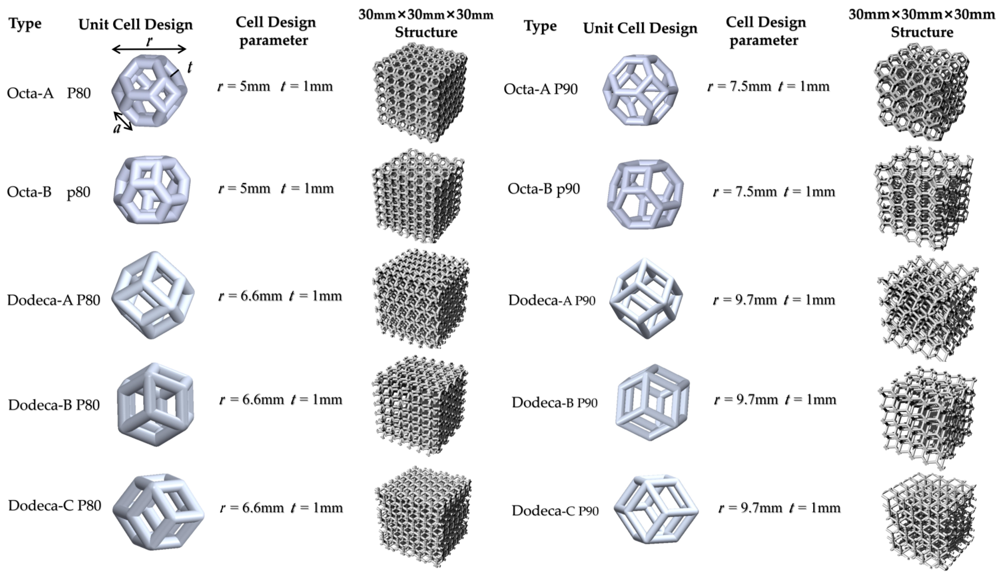
2.1. Design of Cellular Structures

In this work, the structures used were Dodeca and Octa; a three-dimensional image of the unit cell is shown in Figure 1. The length and side length of the unit cell of Octa and Dodeca are a, the radius of the circumcircle of the unit cell is r, the thickness of the unit cell is t and its porosity is P. Three-dimensional Voronoi structures were generated using ordered Voronoi structure-design methods, used to represent real cell structures. Rhinoceros 5 (McNeal, Seattle, WA, USA) and Grasshopper (V 0.9.0076) were used to design these structures. Voronoi has the mathematical definition [30]:
C i = { P | d ( p , S i ) d ( p , S i ) , j i , j = 1 , , n }
where {S1,……,Sn} is the set of seed points defined in three-dimensional Euclidean space, d(p,Si) is the Euclidean distance between position P and seed point Si and Ci is the Voronoi cell associated with seed point Si. One approach to designing a space Voronoi mosaic can be to design various structures with regular shapes according to the space-division principle.
For example, as shown in Figure 2, these points are arranged in a cube composed of eight vertices, and the center of the cube is in a specified space of equal length, width and height. Through these points, the Voronoi mosaic space is divided into nine polyhedrons, the polyhedron in the center of the space is extracted and the frame line is increased to a certain thickness to obtain Octa-A.
In the orthogonal coordinate system of X-Y-Z, Octa-B is A cell of unit geometry obtained after a 54.7-degree rotation about the Y-axis of Octa-A and 45-degree rotation about the Z-axis of Octa-A. Dodeca-A, Dodeca-B and Dodeca-C are rhomboid dodecahedron mono cells with side length a. In the X-Y-Z orthogonal coordinate system, Dodeca-B has A unit geometry after being rotated 90 degrees about the X-axis of Dodeca-A. Dodeca-C’s unit geometry is obtained after a 54.7-degree rotation about the Y-axis of Dodeca-A. The detailed parameters of several structures are shown in Table 1.
The relationship is the same for both unit-cell porosity and diameter normalization. The nominal porosities of the designed porous structure samples are 80 and 90%, respectively. When the thickness of the unit cells of all porous structures is fixed at 1 mm, the diameters of the circumcircles of the unit cells of the samples with 80 and 90% porosity are about 6 and 8 mm, respectively. The cross-section of the above rod-based cellular structure is designed to be circular, and the overall size of all samples is 30 mm × 30 mm × 30 mm. A computer-aided design (CAD) model of the specimens used for numerical simulation is shown in Figure 1.

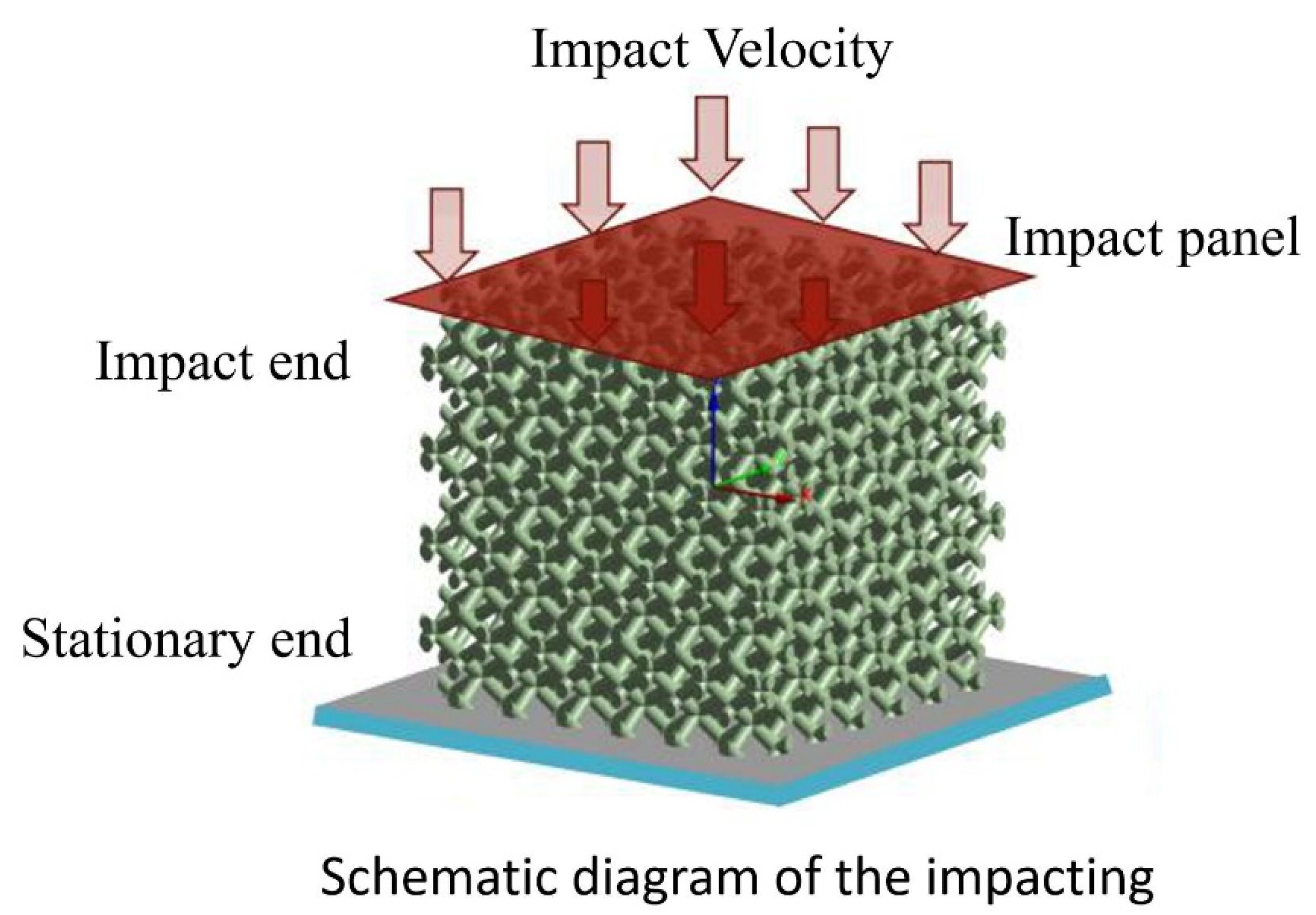
2.2. Impact Finite-Element Modeling

To investigate the impact resistance and energy absorption of the parametric designs of the two porous structures at different impact energies, numerical simulations of the Octa and Dodeca impacts were performed using the Ansys/explicit-dynamics module. The numerical calculation mainly adopted the central difference method. The acceleration vector of the entire structural system at each node at the end time tn of n time steps was calculated by the following formula
a ( t n ) = M 1 [ p ( t n ) F int ( t n ) ]
where p is the nodal external force vector applied to the structure at time t at the end of the nth time step, and Fint is the internal force vector at time tn. Figure 3 and Table 1 show the boundary conditions and geometric parameters of Octa and Dodeca structures. During the modeling process, the specimen was placed between the bottom plate and upper impactor, and the displacement of the bottom plate was fixed, as shown in Figure 3. The base plate was restrained and the impactor was restricted to move only in the Z direction. Four impact energies of 10, 100, 200 and 400 J were used to simulate the impact test, which was equivalent to applying the initial impact velocities of 3.162, 10, 14.14 and 20 m/s. The selected material was aluminum alloy, the material properties of which are given in Table 2. The upper impactor and lower steel plate were set as rigid bodies, and a general algorithm for the contact between the impactor and laminate was established to prevent unrealistic overlap in the contact process. The normal behavior was simulated by hard contact, the contact force was generated based on the penalty contact method and the tangential interaction between contact pairs was defined by the Coulomb friction model. The impactor mass was set to 2 kg and the impact time was 0.001 s. The element surface adopted the automatic single-surface contact and automatic face-to-face contact was used to measure the interaction between the porous structure and rigid plate, where the dynamic friction coefficient was 0.15 (reported by other studies as insensitive parameters) [31,32].

2.3. Mesh Sensitivity Tests

In general, smaller element sizes directly increase the calculation time, but the corresponding calculation results are more accurate. In an actual numerical simulation, when the element size continues to decrease, the accuracy of the calculation results tends to converge. When the element size is reduced to a certain value, the calculation results will gradually tend to stabilize with the reduction in the element size. Therefore, the Dodeca-A structure was selected for the mesh independence test to ensure the accuracy of the calculation results and save on calculation time. The tetrahedral element was selected as the finite-element model because of its strong adaptability. The initial mesh-sensitivity study showed that the in-plane finite-element size should be less than or equal to 2 mm, resulting in negligible differences in the predicted displacement and damage modes. Therefore, this finite-element model was adopted. In this study, grid-independence tests were performed using four sets of grids: 1, 0.5, 0.4 and 0.3 mm. The number of corresponding units was 655,968, 2,723,934, 5,322,279 and 11,469,622, respectively. When the number of elements was greater than or equal to 5,322,279, the various values of contact force and structural displacement tended to be constant, and the maximum deviations of the calculation results were 0.64 and 0.78%, respectively. Therefore, 0.4 mm was chosen as the optimal grid size.

3. Results and Discussion

Considering the cost and time of the experimental study and the limitations of the sample and experimental conditions, the mechanical properties of the porous structure under different structural design parameters, as well as the energy-absorption capacity and deformation mode of the porous structure, were further studied by a numerical simulation.

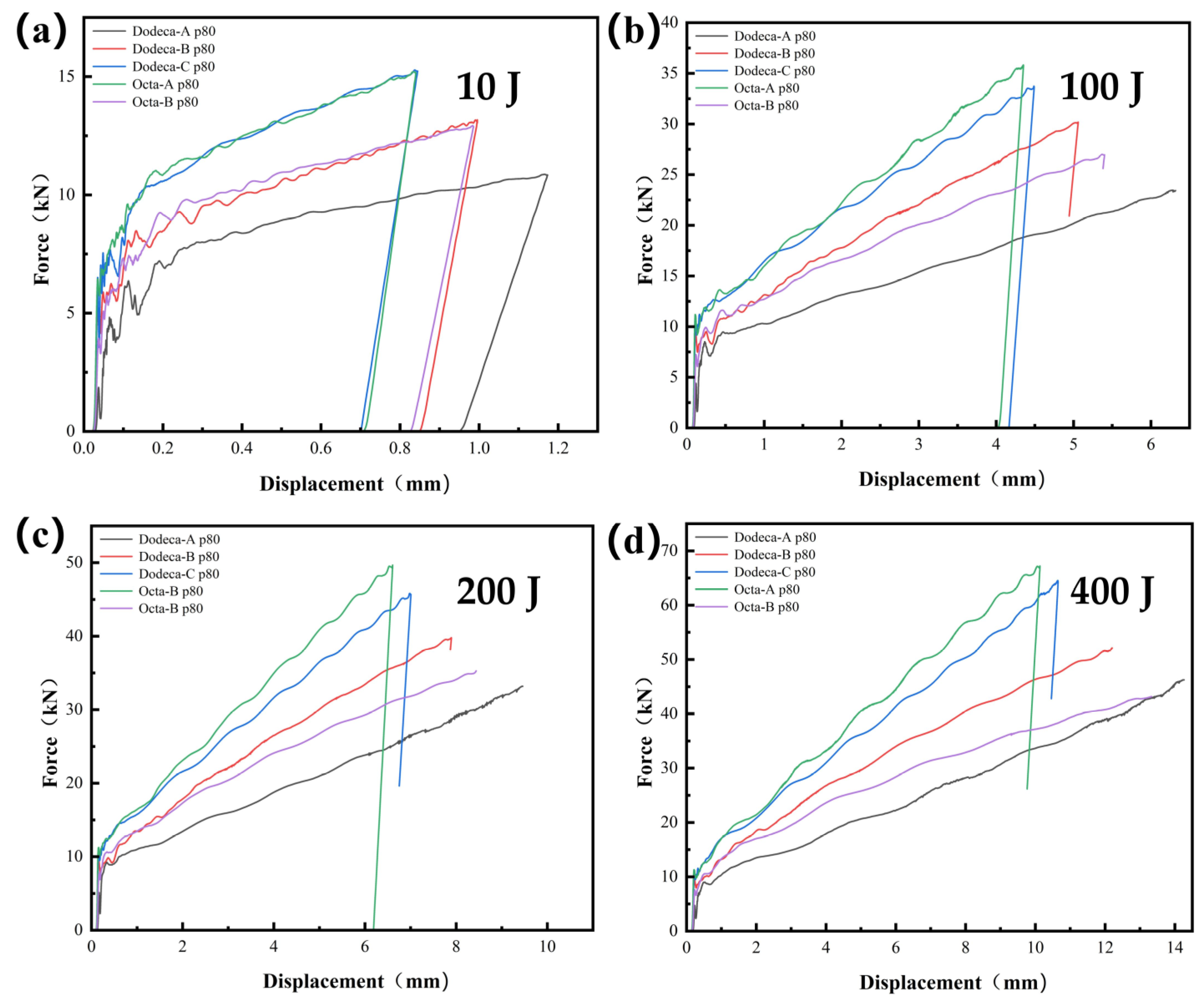
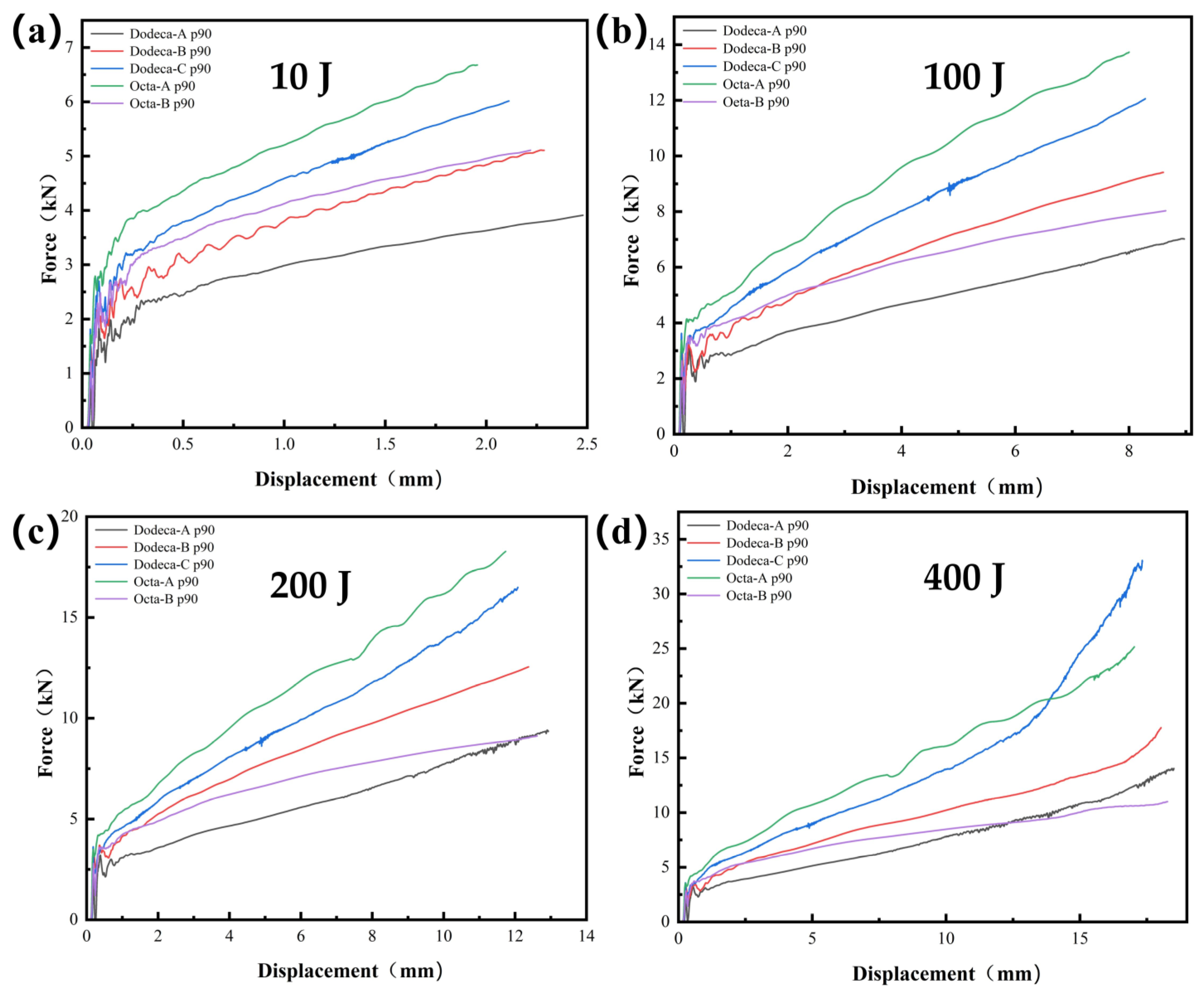
3.1. Load-Displacement Curves

Impact force is one of the key factors with which to study the dynamic responses of structures, revealing the deformation mechanism after an impact. It provides very useful information for the application of this kind of structure in scenarios in which there may be a transient impact. From the finite-element-analysis results, the contact force and displacement curves between the impactor and porous structure can be obtained.
As shown in Figure 4a, at a lower impact energy of 10 J, with the increase in displacement, the interaction force between the impactor and the Octa and Dodeca with 80% porosity peaked in a nonlinear manner. Next, the interaction force between the truncated octahedrons with 80% porosity and the Dodeca decreased sharply, and the displacement rose, indicating that the impactor rebounded after the force peaked. The contact force-displacement curves of the Dodeca and Octa samples with 80% porosity show a perfect closed mode (elastic rebound stage), where the contact force and displacement almost decrease to the axis origin, which confirms that some elastic energy was restored, resulting in a rebound from the impact. This indicates that the impactor rebounded after reaching the peak force, and there was insufficient impact energy to cause damage to the sample.
As shown in Figure 4b–d, the Octa-A, Dodeca-C, Dodeca-B and Octa-B structures with 80% porosity under 100 J energy impact, the Octa-A, Dodeca-B and Dodeca-C structures with 80% porosity under 200 J and the Octa-A and Dodeca-C structures with 80% porosity under 400 J also showed a rebound. This was because the entire impact time was set to 0.001 s, and the impactor rebounded during this time. For the Dodeca-A under 100 J of impact energy, the Dodeca-A and Octa-B under 200 J and the Dodeca-A, Octa-A and Octa-B under 300 J, the interaction force between them and the impactor first increased sharply, then began to oscillate and subsequently rose slowly. In the same shock time, no rebound phenomenon occurred. For the Dodeca and Octa structures with a porosity of 90%, as shown in Figure 5, no rebound phenomenon occurred, indicating that under the impact energy at this moment, the part of the upward kinetic energy converted into the impactor as elastic energy was smaller than the downward kinetic energy of the impactor. The remaining energy was absorbed by the porous structure, resulting in irreversible deformation of the structure. When subjected to the same impact energy, the force-displacement curves of the 90% porosity structure showed similar trends, but different peak forces and contact displacements.

3.2. Energy Absorption Performance

To better evaluate the energy-absorption performance of porous structures, three main energy absorption metrics are used: peak force (PF), energy absorption (Ea) and specific energy absorption (SEA).
The peak force (PF) is the maximum initial force during the entire energy-absorption process. Ea is obtained by integrating the force-displacement curve under impact, and is expressed as:
E a = 0 d F ( x ) d ( x )
where d represents the displacement of the structure during energy absorption and F represents the impact force.
Impact-resistant structures are required to meet the conditions of energy absorption, that is, fully absorb impact energy. SEA, which is defined as the energy absorbed per unit mass of the structure, represents structures’ utilization efficiency of energy absorption. The higher the SEA value, the better the energy absorption efficiency. SEA is defined as:
S E A = E m
where m represents the total mass of the structure and E represents the energy absorbed by the structure during an impact.

3.2.1. Influence of Porosity

To explore the impact of the porosity on the impact properties of the Dodeca and Octa structures, those with 80 and 90% porosity were examined to determine how they withstood different impact energies. Figure 4 and Figure 5 show the corresponding force-displacement curves of the Dodeca and Octa structures with different porosities under different impact energies by numerical calculation. Through the curve comparison, it was found that under the same impact energy, the slopes of the structures with lower porosity was larger than those of the structures with higher porosity. Figure 6 and Figure 7 are based on the force-displacement curves of Figure 4 and Figure 5, respectively, combined with the peak force, energy absorption and SEA, to explore the energy-absorption indices of different porous structures. It can clearly be seen that when subjected to the same impact energy, the peak force decreased with the increase in porosity.
As the porosity increased from 80 to 90%, the peak forces of the Dodeca-A and Octa-A structures decreased to 35 and 46%, respectively, at 10 J of impact energy. Similar results were also obtained at impact energies of 100, 200 and 400 J. Figure 6 and Figure 7 show that when the impact energy was small, the porosity had little effect on the energy absorption, while when the impact energy was large, the energy absorption of the 80%-porosity structures was significantly greater than that of the 90%-porosity structures. At impact energies of 10, 100 and 200 J, the SEA increased with increasing porosity, which was mainly because the increase in the mass of the porous structures affected the energy-absorption capacity. As shown in Figure 6d and Figure 7d, when the porosity increased from 80 to 90% under a large amount of impact energy, the energy absorption and SEA improved, which indicates that porous structures with lower porosity absorbed higher impact energies and exhibited better impact resistance. Therefore, when the impact energy is relatively large, samples with 80%-porosity structures, i.e., with lower porosity, can be selected from the perspectives of energy absorption and economy. By contrast, when the impact energy was relatively small, a sample with a higher-porosity structure should be used. The 90%-porosity samples were found to have a good energy-absorption effect and impact-resistance characteristics; overall, these samples could absorb more than 89% of the impact energy.

3.2.2. Influence of Unit-Cell Shape and Rotating Unit Cell

In the impact simulation, for the Dodeca and Octa structures with the same height (30 mm) and porosity (80%), we rotated the Dodeca at two different angles and the Octa at one angle to evaluate the effect of the rotation angle. Figure 4 compares the force-displacement curves of the Dodeca and Octa structures under different impact energies at different rotation angles through numerical calculation. The results show that the force-displacement curves of the porous structures were significantly affected by the rotation angle.
For a more direct comparison, according to the force-displacement curves of the Dodeca and Octa structures in Figure 4, the energy-absorption indices of the Dodeca and Octa porous structures with different rotation angles, shown in Figure 6, were obtained.
As can be seen in Figure 6a, under the impact energy of 10 J, the peak forces of the Dodeca-B and -C structures are 18% and 35% higher than those of the Dodeca-A structure, respectively, while the peak force of the Octa-B structure is higher than that of the Octa-A structure 16% lower, indicating that the impact resistance of the structure is closely related to the geometry of the pores. It can be seen from Table 1 that the number of oblique edges of the unit cell can be changed by rotating it. The porous structures with more oblique edges had better stiffness and resisted higher impact loads, resulting in higher peak forces. The energy-absorption levels of Dodeca-B and -C, obtained from the rotation of Dodeca-A, increased by 2 and 3%, respectively, while the energy absorption was slightly decreased from the Octa-A rotation to Octa-B. However, the porosity SEA variation law and energy absorption were the same because, relative to the porous structure, there was almost no change in mass at the same porosity. To sum up, under the impact energy of 10 J, the Dodeca-C—obtained by rotating Dodeca 54.7 degrees in the y direction—had the best energy absorption, at 92% of the impact energy.
As shown in Figure 6b–d, under the impact energy of 100 J, when rotating the Dodeca-A unit cell to obtain Dodeca-B and -C, the energy absorption increaseD gradually, while rotating the Octa unit cell led to reduced energy absorption. This situation became more obvious when the impact energy was 200 or 400 J. Overall, the research shows that the rotating unit cell had a significant impact on the impact resistance of the porous structure, and that a reasonable rotation angle can significantly improve the energy-absorption capacity of the porous structure.

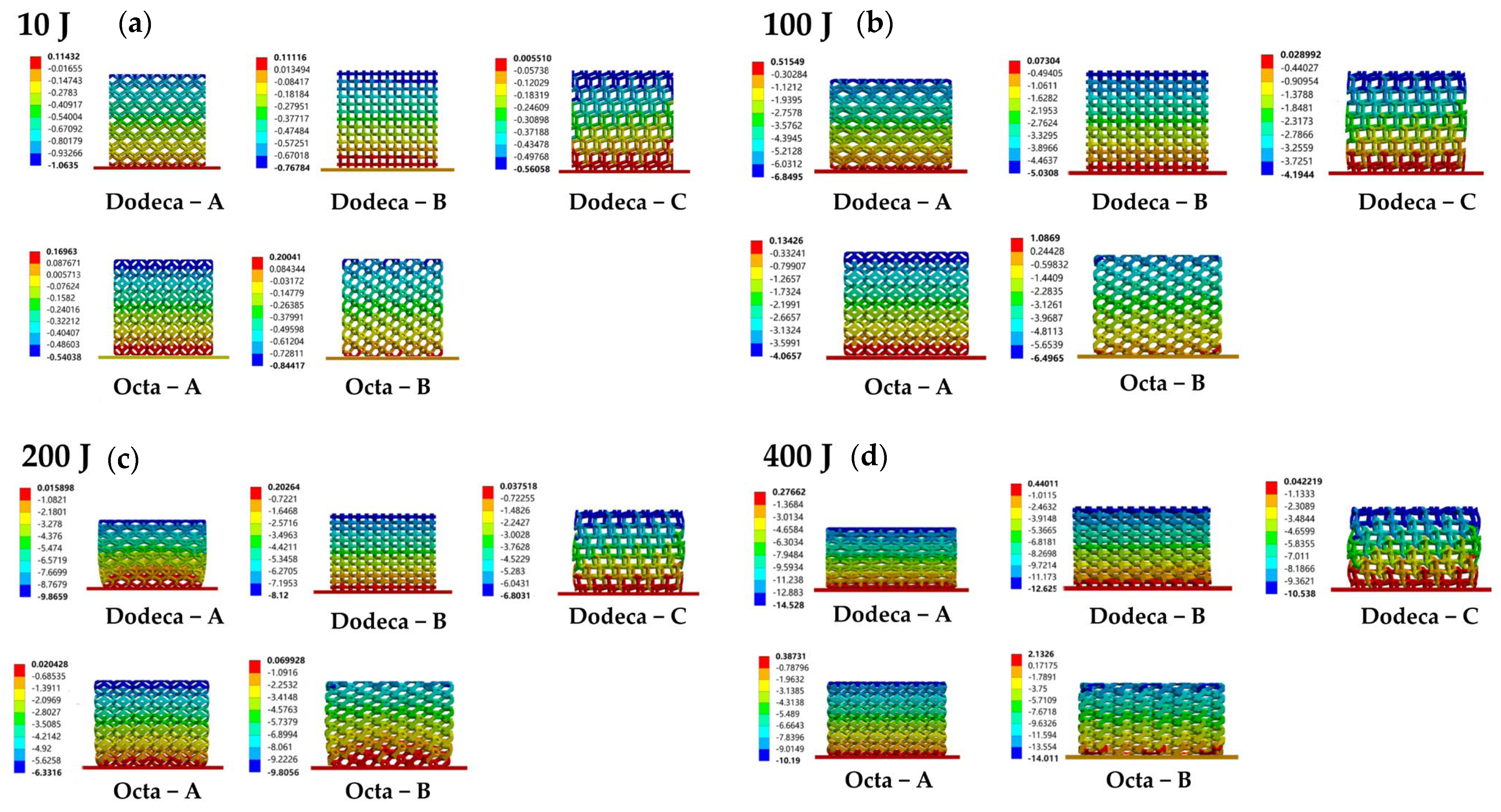
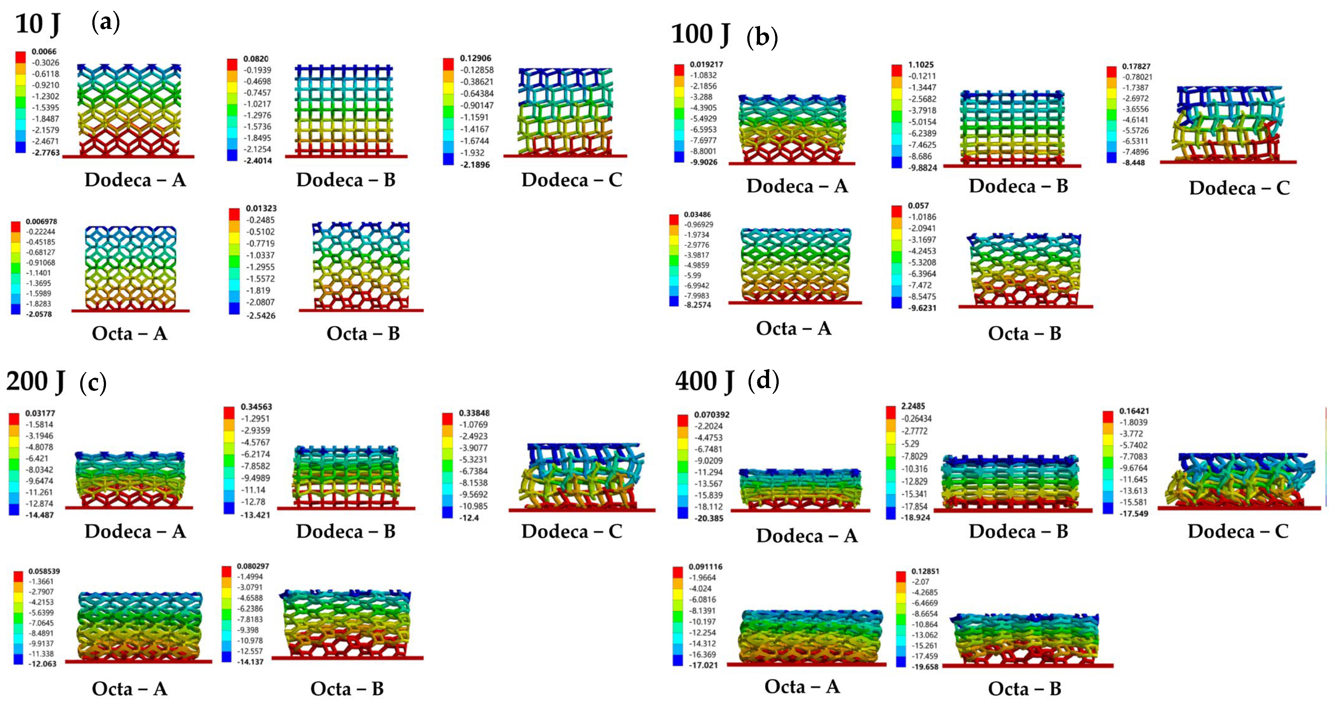
3.3. Deformation Modes

3.3.1. Influence of Porosity

Figure 8 and Figure 9 show the corresponding deformation modes of the Dodeca and Octa specimens with different levels of porosity when the impact energy was 10, 100, 200 or 400 J. When the impact energy was 10 J, no obvious impact deformation was found in the porous structures with 80% porosity and 90% porosity, indicating that when the impact energy was not sufficient to cause structural damage, the difference in the amount of deformation of the porous structures with different porosities was not large. When the impact energy increased to 100 J, the porous structures with two different levels of porosity began to deform and fracture obviously, and the degree of deformation increased with the increase in porosity. When the impact energy reached 200 or 400 J, the deformation degrees of the porous structures of the two levels of porosity were significantly different from one another.
In general, through a comparative analysis, it was found that under the same impact energy, the porous structures with high porosity suffered more severe deformation.

3.3.2. Influence of Unit-Cell Shape and Rotating Unit Cell

Figure 9 shows a comparison of the deformation of the Dodeca and Octa at imp act energies of 10, 100, 200 and 400 J and at 90% porosity. Under the impact energy of 10 J, as shown in Figure 9a, the Dodeca-A and -B structures both started to deform from the top, and the deformation was relatively uniform, while for the Dodeca-C structure, we can clearly see that the left half began to deform first. In comparison, the deformation of the Octa-A structure was also relatively uniform, while the deformation mode of Octa-B had a tendency to extend from the top to the outside. With the increase in impact energy, the deformation of the Dodeca and Octa deepened.
Under the impact energy of 100 J, as shown in Figure 9b, the Dodeca-A structure exhibited dense deformation in the middle and loose deformation on both sides, while the Dodeca-B exhibited dense deformation at both ends and sparse deformation in the middle. Interestingly, the Dodeca- C deformation presented a “z”-shape; this was because, since it had more oblique edges, was the edge of the unit cell broke more easily. The Octa-A structure, meanwhile, showed slight shearing, while the middle and lower parts of the Octa-B structure deformed first (the bottom was semicircular and convex).
Under the impact energies of 200 and 400 J, as shown in Figure 9c,d, the deformation was more serious. Since the intermediate region of the Dodeca-A was subjected to the instantaneous impact load, the porous structure fractured and collapsed, failing to continue to absorb the impact energy, resulting in cracks in the central area that extended to both ends. While the Dodeca-C first deformed in the left and sheared in the middle, part of the impact load was weakened by sliding friction, which was conducive to energy absorption. For the Octa-B, because the top was too weak, the deformation first expanded from the top, and then the middle part also deformed and broke, which did not produce good energy absorption.
Based on the above analysis, it can be concluded that the deformation and porosity of a porous structure are closely related to the unit-cell shape. Under the same impact energy, porous structures with lower porosity can provide better impact resistance due to the stiffness and strength of the aluminum alloy material. However, in terms of the specific energy absorption of porous structures, it is not a case of “the lower the porosity, the better”. The shape of the porous structure unit cell is also key to the optimal design of porous structures.

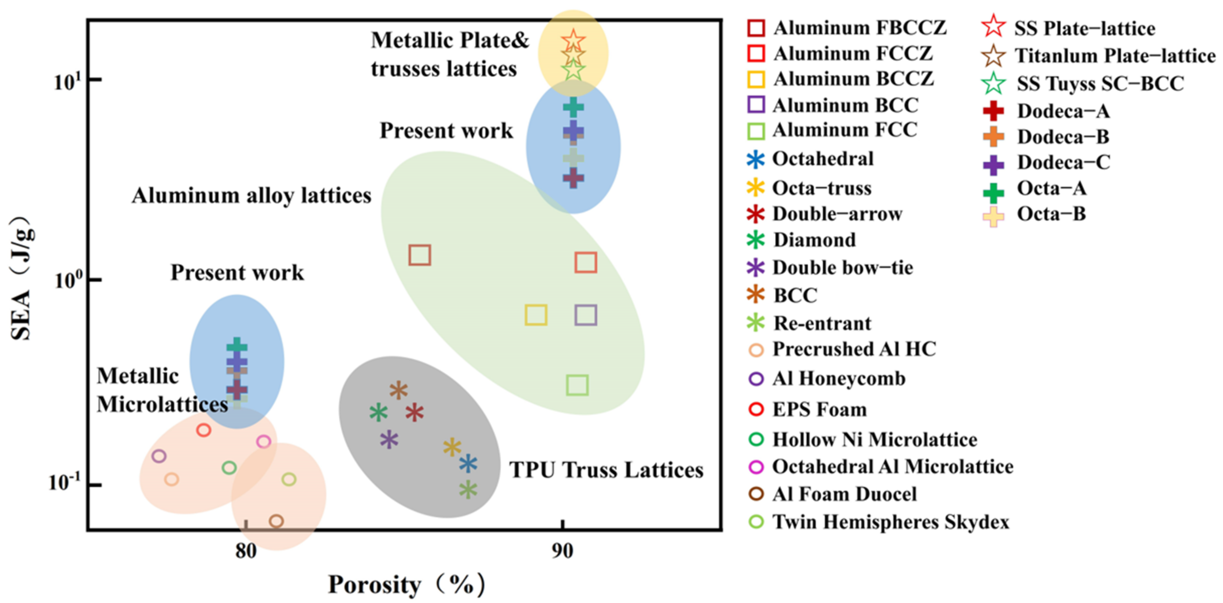
3.4. Comparative Specific Energy-Absorption Characteristics of Porous Structures Studied in This Paper

The specific energy absorptions of the Dodeca-C and Octa-A with 90% porosity were about 8.3 J/g and 9.3 J/g, which is comparable to the lattice structure of traditional titanium alloy. In addition, the absorption is higher than that of conventional aluminum lattices [33] and other metamaterials [34,35], as shown in Figure 10. Looking ahead, future work will construct these geometries using selective laser melting (SLM), to study the impact behavior of the two structures when varying the impact angle and time, in order to explain the deformation and damage mechanisms through experimental studies.

4. Conclusions

In this paper, a method based on spatial Voronoi subdivision was applied to the design of ordered Voronoi structures. The basic structure (Octa-A, Dodeca-A) and rotating body (Octa-B, Dodeca-B/-C) were designed, and a numerical simulation was carried out based on the finite-element method. The effects of different impact energies, porosities, unit-cell shapes and rotating unit cells on the two basic structures and their rotating bodies were studied, and the following important conclusions were drawn:
  • For the porous structures subjected to various impact energies, the force-displacement curve showed three modes: one was a single peak that then sharply descended, almost back to the origin; the next was a single peak, followed by a slight decrease, but without approaching the origin; and the third increased sharply and then experienced oscillations, before beginning to rise slowly. In the first, the impact energy was not sufficient to cause damage to the sample; in the second, the impactor rebounded within the impact time; and in the third, the impactor did not.
  • When subjected to impact, the shape of the unit cell has a significant effect on the impact resistance of the porous structure. By rotating the unit cell, its number of oblique edges can be changed; a porous structure with more oblique edges has better stiffness and can resist higher impact loads. The results show that the Dodeca structure rotated 54.7 degrees around the y-axis to absorb energy the best, while the energy-absorption behavior of the Octa structure decreased after rotation.
  • At the same impact energy, the stiffness of porous structures increases as their porosity decreases. When the impact energy is not sufficient to destroy a porous structure, its porosity has no significant effect on the energy absorption, but for economic reasons, it is recommended to use a higher porosity (90%), through which about 89% or more of the impact energy can be absorbed. When the impact energy is large, porous structures with low porosity (80%) may show stronger energy-absorption characteristics.
Looking ahead, future work will construct these geometries using selective laser melting (SLM), to study the impact behavior of the two structures when varying the impact angle and time, in order to explain the deformation and damage mechanisms through experimental studies.

Author Contributions

Conceptualization, S.L. and M.Z.; methodology, S.L., M.Z. and X.Y.; software, S.L. and M.Z.; validation, S.L., M.Z. and X.Y.; formal analysis, S.L.; investigation, S.L. and M.Z.; resources, S.G., B.H. and X.Y.; data curation, S.L. and M.Z.; writing—original draft preparation, S.L.; writing—review and editing, S.L., M.Z. and X.Y.; visualization, S.L.; supervision, X.Y.; project administration, S.G., B.H. and X.Y.; funding acquisition, X.Y. All authors have read and agreed to the published version of the manuscript.

Funding

This research was funded by Shanghai Sailing Program grant number 19YF1434300.

Institutional Review Board Statement

Not applicable.

Informed Consent Statement

Not applicable.

Data Availability Statement

Data sharing is not applicable to this article.

Conflicts of Interest

The authors declare no conflict of interest.

References

  1. Paolini, A.; Kollmannsberger, S.; Rank, E. Additive manufacturing in construction: A review on processes, applications, and digital planning methods. Addit. Manuf. 2019, 30, 100894. [Google Scholar] [CrossRef]
  2. Schaedler, T.A.; Carter, W.B. Architected Cellular Materials. Annu. Rev. Mater. Sci. 2016, 46, 187–210. [Google Scholar] [CrossRef]
  3. Ngoc, S.H.; Lu, G. A review of recent research on bio-inspired structures and materials for energy absorption applications. Compos B Eng. 2020, 181, 107406. [Google Scholar]
  4. Fang, J.; Sun, G.; Qiu, N.; Kim, N.H.; Li, Q. On design optimization for structural crashworthiness and its state of the art. Struct. Multidiscip. Optim. 2016, 55, 1091–1119. [Google Scholar] [CrossRef]
  5. Xu, F.; Zhang, X.; Zhang, H. A review on functionally graded structures and materials for energy absorption. Eng. Struct. 2018, 171, 309–325. [Google Scholar] [CrossRef]
  6. Lu, L.; Sharf, A.; Zhao, H. Build-to-Last: Strength to Weight 3D Printed Objects. ACM Trans Graph. 2014, 33, 97. [Google Scholar] [CrossRef]
  7. Quey, R.; Dawson, P.R.; Barbe, F. Large-scale 3D random polycrystals for the finite element method: Generation, meshing and remeshing. Comput. Methods Appl. Mech. Eng. 2011, 200, 1729–1745. [Google Scholar] [CrossRef] [Green Version]
  8. Calka, P. An explicit expression for the distribution of the number of sides of the typical Poisson-Voronoi cell. Adv. Appl. Probab. 2003, 35, 863–870. [Google Scholar] [CrossRef]
  9. Hug, D.; Reitzner, M.; Schneider, R. Large Poisson-Voronoi cells and Crofton cells. Adv. Appl. Probab. 2004, 36, 667–690. [Google Scholar] [CrossRef] [Green Version]
  10. Falco, S.; Jiang, J.; De Cola, F.; Petrinic, N. Generation of 3D polycrystalline microstructures with a conditioned Laguerre-Voronoi tessellation technique. Comput. Mater. Sci. 2017, 136, 20–28. [Google Scholar] [CrossRef]
  11. Shao, J.; Zhang, W.; Shen, A.; Mellado, N.; Cai, S.; Luo, L.; Wang, N.; Yan, G.; Zhou, G. Seed point set-based building roof extraction from airborne LiDAR point clouds using a top-down strategy. Autom. Constr. 2021, 126, 103660. [Google Scholar] [CrossRef]
  12. Zheng, N.; Yu, L. Numerical investigation of pressure drop and heat transfer through open cell foams with 3D La-guerre-Voronoi model—ScienceDirect. Int. J. Heat Mass Transf. 2017, 113, 819–839. [Google Scholar]
  13. Ćwieka, K.; Wejrzanowski, T.; Kurzydłowski, K.J. Incorporation of the Pore Size Variation to Modeling of the Elastic Behavior of Metallic Open-Cell Foams. Arch. Met. Mater. 2017, 62, 259–262. [Google Scholar] [CrossRef] [Green Version]
  14. Liu, B.; Cao, W.; Zhang, L.; Jiang, K.; Lu, P. A design method of Voronoi porous structures with graded relative elasticity distri-bution for functionally gradient porous materials. Int. J. Mech. Mater. Des. 2021, 17, 863–883. [Google Scholar] [CrossRef]
  15. Chen, D.; Kitipornchai, S.; Yang, J. Dynamic response and energy absorption of functionally graded porous structures. Mater. Des. 2018, 140, 473–487. [Google Scholar] [CrossRef] [Green Version]
  16. Peixinho, N.; Carvalho, O.; Areias, C.; Pinto, P.; Silva, F. Compressive properties and energy absorption of metal-polymer hybrid cellular structures. Mater. Sci. Eng. A 2020, 794, 139921. [Google Scholar] [CrossRef]
  17. Tan, J.H.K.; Sing, S.L.; Yeong, W.Y. Microstructure modelling for metallic additive manufacturing: A review. Virtual Phys. Prototyp. 2019, 15, 87–105. [Google Scholar] [CrossRef]
  18. Tancogne-Dejean, T.; Diamantopoulou, M.; Gorji, M.B.; Bonatti, C.; Mohr, D. 3D Plate-Lattices: An Emerging Class of Low-Density Metamaterial Exhibiting Optimal Isotropic Stiffness. Adv. Mater. 2018, 30, e1803334. [Google Scholar] [CrossRef]
  19. Berger, J.B.; Wadley, H.N.G.; McMeeking, R.M. Mechanical metamaterials at the theoretical limit of isotropic elastic stiffness. Nature 2017, 543, 533–537. [Google Scholar] [CrossRef] [Green Version]
  20. Şerban, D.A.; Linul, E.; Voiconi, T.; Marşavina, L.; Modler, N. Numerical evaluation of two-dimensional micromechanical structures of anisotropic cellular materials: Case study for polyurethane rigid foams. Iran. Polym. J. 2015, 24, 515–529. [Google Scholar] [CrossRef]
  21. Maskery, I.; Aboulkhair, N.T.; Aremu, A.O.; Tuck, C.J.; Ashcroft, I.A.; Wildman, R.D.; Hague, R.J.M. A mechanical property evaluation of graded density Al-Si10-Mg lattice structures manufactured by selective laser melting. Mater. Sci. Eng. A 2016, 670, 264–274. [Google Scholar] [CrossRef] [Green Version]
  22. Cao, X.; Ren, X.; Zhao, T.; Li, Y.; Xiao, D.; Fang, D. Numerical and theoretical analysis of the dynamic mechanical behaviour of a modified rhombic dodecahedron lattice structure. Int. J. Mech. Mater. Des. 2020, 17, 271–283. [Google Scholar] [CrossRef]
  23. Yue, X.-Z.; Matsuo, K.; Kitazono, K. Compressive Behavior of Open-Cell Titanium Foams with Different Unit Cell Geometries. Mater. Trans. 2017, 58, 1587–1592. [Google Scholar] [CrossRef] [Green Version]
  24. Gibson, L.J. Mechanical Behavior of Metallic Foams. Annu. Rev. Mater. Sci. 2000, 30, 191–227. [Google Scholar] [CrossRef]
  25. Tancogne-Dejean, T.; Spierings, A.B.; Mohr, D. Additively-manufactured metallic micro-lattice materials for high specific energy absorption under static and dynamic loading. Acta Mater. 2016, 116, 14–28. [Google Scholar] [CrossRef]
  26. Erban, D.A.; Negru, R.; Srndan, S.; Belgiu, G.; Maravina, L. Numerical and experimental investigations on the mechanical prop-erties of cellular structures with open Kelvin cells. Mech. Adv. Mater. Struct. 2019, 28, 1367–1376. [Google Scholar] [CrossRef]
  27. Kraynik, A.M.; Reinelt, D.A.; Van Swol, F. Structure of Random Foam. Phys. Rev. Lett. 2004, 93, 208301. [Google Scholar] [CrossRef]
  28. Babaee, S.; Jahromi, B.H.; Ajdari, A.; Nayeb-Hashemi, H.; Vaziri, A. Mechanical properties of open-cell rhombic dodecahedron cellular structures. Acta Mater. 2012, 60, 2873–2885. [Google Scholar] [CrossRef]
  29. Hedayati, R.; Sadighi, M.; Mohammadi-Aghdam, M.; Zadpoor, A. Mechanical behavior of additively manufactured porous biomaterials made from truncated cuboctahedron unit cells. Int. J. Mech. Sci. 2016, 106, 19–38. [Google Scholar] [CrossRef]
  30. Yue, D.; Liang, H.; Xie, D.; Mao, N.; Zhao, J.; Tian, Z.; Wang, C.; Shen, L. Design and statistical analysis of irregular porous scaffolds for orthopedic reconstruction based on voronoi tessellation and fabricated via selective laser melting (SLM). Mater. Chem. Phys. 2020, 239, 121968. [Google Scholar]
  31. Zhang, J.; Wang, Z.; Zhao, L. Dynamic response of functionally graded cellular materials based on the Voronoi model. Compos. Part B Eng. 2016, 85, 176–187. [Google Scholar] [CrossRef]
  32. Ma, G.; Ye, Z.; Shao, Z. Modeling loading rate effect on crushing stress of metallic cellular materials. Int. J. Impact Eng. 2009, 36, 775–782. [Google Scholar] [CrossRef]
  33. Maconachie, T.; Leary, M.; Tran, P.; Harris, J.; Liu, Q.; Lu, G.; Ruan, D.; Faruque, O.; Brandt, M. The effect of topology on the quasi-static and dynamic behaviour of SLM AlSi10Mg lattice structures. Int. J. Adv. Manuf. Technol. 2021, 118, 4085–4104. [Google Scholar] [CrossRef]
  34. Kumar, S.; Wardle, B.L.; Arif, M.F.; Ubaid, J. Stress Reduction of 3D Printed Compliance-Tailored Multilayers. Adv. Eng. Mater. 2017, 20, 1700883. [Google Scholar] [CrossRef]
  35. Andrew, J.J.; Schneider, J.; Ubaid, J.; Velmurugan, R.; Gupta, N.K.; Kumar, S. Energy absorption characteristics of additively manufactured plate-lattices under low- velocity impact loading. Int. J. Impact Eng. 2020, 149, 103768. [Google Scholar] [CrossRef]
Figure 1. Unit-cell design, cell-design parameters and CAD models.
Metals 12 01189 g001
Figure 2. Design process of random Voronoi structure: (a) Octa-A, (b) Octa-B, (c) Dodeca-A, (d) Dodeca-B and (e) Dodeca-C.
Metals 12 01189 g002
Figure 3. Finite-element model for drop-hammer test.
Metals 12 01189 g003
Figure 4. Force-displacement curves of 80%-porosity structures tested at different impact energies: (a) 10 J, (b) 100 J, (c) 200 J and (d) 400 J.
Metals 12 01189 g004
Figure 5. Force-displacement curves of 90%-porosity structures tested at different impact energies: (a) 10 J, (b) 100 J, (c) 200 J and (d) 400 J.
Metals 12 01189 g005
Figure 6. Comparison of energy-absorption indices of 80%-porosity structures under different impact energies: (a) 10, (b) 100, (c) 200 and (d) 400 J.
Metals 12 01189 g006
Figure 7. Comparison of energy-absorption indices of 90%-porosity structures under impact energy: (a) 10, (b) 100, (c) 200 and (d) 400 J.
Metals 12 01189 g007
Figure 8. Comparison of deformation modes of 80%-porosity structures at different impact energies: (a) 10, (b) 100, (c) 200 and (d) 400 J.
Metals 12 01189 g008
Figure 9. Comparison of deformation modes of 90%-porosity structures at different impact energies: (a) 10, (b) 100, (c) 200 and (d) 400 J.
Metals 12 01189 g009
Figure 10. Comparison of specific energy absorption of the porosity structure considered in the present work with the extant literature [33,34,35].
Metals 12 01189 g010
Table 1. Specific geometric parameters of the CAD models.
StructureNominal Porosity (%)True Porosity (%)Unit Cell Size (mm)Volume of Cellular Structures (mm3)Number of Oblique
Edges
Dodeca-A8080.166.65356.72612
Dodeca-A9089.879.72734.92712
Dodeca-B8080.166.65356.72918
Dodeca-B9089.879.72735.29318
Dodeca-C8079.826.65449.09424
Dodeca-C9089.569.72818.53724
Octa-A8079.3855568.37624
Octa-A9089.957.52712.6724
Octa-B8079.7855458.30118
Octa-B9089.537.52827.83018
Table 2. Material properties used in FE model.
ItemsValues
Density2770 kg/m3
Young’s modulus71,000 MPa
Poisson’s ratio0.33
Tensile ultimate strength
Tensile yield strength
246.1 MPa
164.8 MPa
Publisher’s Note: MDPI stays neutral with regard to jurisdictional claims in published maps and institutional affiliations.

